
606 S3 - Speaker BOWERS & WILKINS - Free user manual and instructions
Find the device manual for free 606 S3 BOWERS & WILKINS in PDF.
User questions about 606 S3 BOWERS & WILKINS
0 question about this device. Answer the ones you know or ask your own.
Ask a new question about this device
Download the instructions for your Speaker in PDF format for free! Find your manual 606 S3 - BOWERS & WILKINS and take your electronic device back in hand. On this page are published all the documents necessary for the use of your device. 606 S3 by BOWERS & WILKINS.
USER MANUAL 606 S3 BOWERS & WILKINS
Welcome and thank you for choosing Bowers & Wilkins.
Our founder, John Bowers, believed that imaginative design, innovative engineering and advanced technology were keys that could unlock the enjoyment of audio in the home. His belief is one that we continue to share and inspires every product we design.
This is a high performance product that rewards thoughtful installation, so we suggest that you take some time to read this manual before you begin. Continue on page 3 →
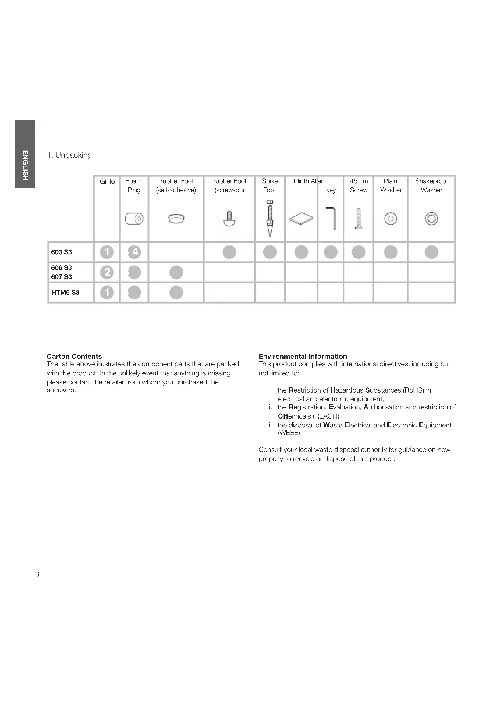
| Grille | Foam Plug | Rubber Foot (self-adhesive) | Rubber Foot (screw-on) | Spike Foot[CAV] | Plinth Allen  | Key[7CBY] | 45mm Screw[bruxd] | Plain Washer[WD0W] | Shakeproof Washer | |
| 603 S3 |  |  |  |  |  |  |  |  |  | |
| 606 S3607 S3 |  |  |  | |||||||
| HTM6 S3 |  | [38W4] |  |
Carton Contents
The table above illustrates the component parts that are packed with the product. In the unlikely event that anything is missing please contact the retailer from whom you purchased the speakers.
Environmental Information
This product complies with international directives, including but not limited to:
i. the Restriction of Hazardous Substances (RoHS) in electrical and electronic equipment,
ii. the Registration, Evaluation, Authorisation and restriction of CHemicals (REACH)
iii. the disposal of Waste Electrical and Electronic Equipment (WEEE).
Consult your local waste disposal authority for guidance on how properly to recycle or dispose of this product.
- Positioning 603 S3

text_image
Technical diagram showing assembly of a bolt and nut assembly with labeled components and a magnified inset detail.Speaker Installation
603 S3
603 S3 is intended to be floor mounted only. For proper stability, always install the provided plinth, then ensure that the speakers stand firmly on the floor using the spike or rubber feet supplied.
You may attach the plinth during the unpacking process, following the illustrations above or the diagrams on the top flap of the carton.
Warning
The plinth MUST always be used, with the rubber or spike feet inserted into the plinth. DO NOT insert rubber or spike feet directly into the cabinet.
natural_image
Simple line drawing of a Y-shaped object with a central conical feature and a circular arrow symbol (no text or labels)
text_image
<36mm
text_image
<15mm
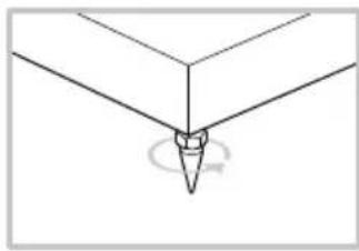
Important Safety Notice
Sharp spikes, do not touch.
The spike feet are designed to pierce carpet and rest on the floor surface. Initially, screw the lock nuts onto the spikes just far enough to leave the nuts floating just above the carpet when the spikes are resting on the floor beneath. Then, screw the spikes fully into the threaded inserts in the plinth. If the cabinet rocks when placed on the floor, unscrew the two spikes that do not touch the floor until the cabinet rests firmly without rocking. Finally, lock the nuts against the base and gently tighten the nut to stop the spike foot rotating. It may be more convenient to fit and adjust the spike feet after speaker positioning has been optimised.
If there is no carpet and you wish to avoid scratching the floor surface, use either a protective metal disc (a coin perhaps) between the spike and the floor, or use the supplied rubber feet. Fit the rubber feet and level the cabinet in the same manner as with the spike feet.
natural_image
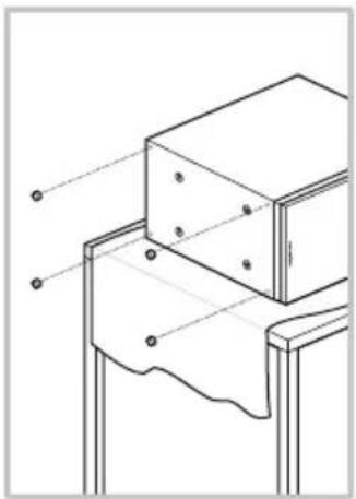
Technical line drawing of a mechanical assembly with mounting brackets and alignment lines (no text or symbols)606 S3 / 607 S3
The 606 S3 and 607 S3 are primarily designed to be mounted on a dedicated floor stand (FS-600 S3), but may be placed on a shelf if preferred. However, it should be noted that this offers less flexibility to optimise the speaker's performance. If shelf placement must be used, we recommend using the foam plugs (supplied) to optimise port performance (see Section 4: Fine-Tuning).
In both installation cases, the speakers' tweeters should be approximately at ear height at your usual listening position.
Note: If using a shelf, ensure that it is strong enough to properly support the weight and fit the four self-adhesive rubber feet to the underside of the speaker.
HTM6 S3
If using a projection television with an acoustically transparent screen, position the speaker behind the centre of the screen. Otherwise, position it either directly below or above the screen using either a floor stand, furniture unit or wall shelf, ensuring the speaker is as close to ear height as possible. If the speaker is to be placed either on a shelf or in a rack shared with other AV equipment, fix the four self-adhesive rubber feet to the base of the speaker. They provide a degree of vibration isolation.

text_image
>0.5m 1.5m - 3m >0.5mSpeaker Positioning
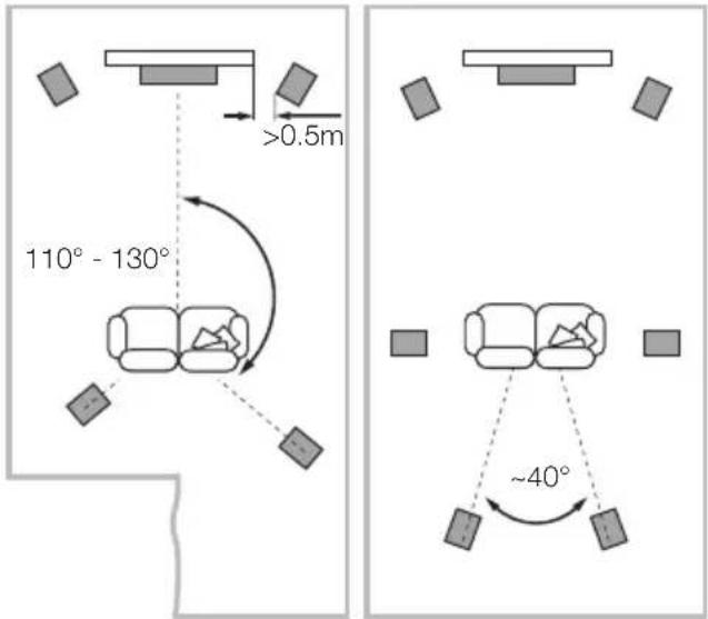
In either stereo or home theatre installations, try to ensure that the immediate surroundings of each speaker are similar in acoustic character. For example, if one speaker is adjacent to bare walls while the other is adjacent to soft furnishings and curtains, both the overall sound quality and the stereo image are likely to be compromised.
Conventional Stereo Systems
To begin with, the speakers should be positioned between 1.5m and 3m apart at two corners of an equilateral triangle completed by the listening area at the third corner. The speakers should be placed at least 0.5m away from the back and any side walls (as per the illustration above).
5 Channels 7 Channels

text_image
>0.5m 110° - 130° ~40°Home Theatre Systems
If the speakers are to be used for the front channels in a home theatre system, they should be placed closer together than for 2-channel audio, because the surround channels tend to widen the image. Positioning the speakers within approximately 0.5m of the sides of the screen will also help keep the sound image in scale with the visual image. As with conventional stereo positioning, the speakers should ideally be at least 0.5m away from any side walls.

text_image
0.5m - 1m 0.5m - 1mStray Magnetic Fields
The speaker drive units create stray magnetic fields that extend beyond the boundaries of the cabinet. We recommend you keep magnetically sensitive articles (CRT television and computer screens, computer discs, audio and video tapes, swipe cards and the like) at least 0.5m from the speaker. LCD, OLED and plasma screens are not affected by magnetic fields.
- Connections
Conventional Connection Bi-Wired Connection

text_image
-LF -HF +LF +HF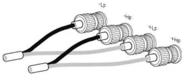
text_image
-LF -HF +LF +HF
Important Safety Notice
All connections should be made with the audio equipment switched off. When using audio equipment in normal operation, touching uninsulated speaker
terminals or wiring may result in an unpleasant sensation. The 600 S3 speaker terminals accept a variety of cable terminations: 4mm banana plugs, 6mm and 8mm (1/4 in and 5/16 in) spades, or bare wires up to 4mm (5/32 in) diameter.

Important Safety Notice
In certain countries, notably those in Europe, the use of 4mm banana plugs is considered a potential safety hazard, because they may be inserted into the holes
of unshuttered mains supply sockets. In order to comply with European CENELEC safety regulations, the 4mm holes in the ends of the terminals are blocked by plastic pins. If you are using the products in any country where these conditions apply, you should ensure that any banana plugs cannot be used in an unsafe manner by children or other uninformed persons. The plastic pins can be removed if you wish to use banana plugs.
Ask your dealer for advice when selecting speaker cable. Keep its total impedance below the maximum recommended in the speaker specification and use a low inductance cable to avoid attenuation of high frequencies.
There are two linked pairs of terminals on the back of the speaker. For conventional connection (above left), the terminal links should remain in place (as delivered) and just one pair of terminals connected to the amplifier. For bi-wire connections or bi-amplification (above right), the terminal links should be removed and each pair of terminals connected to the amplifier or amplifiers independently. Bi-wiring can improve the resolution of low-level detail.
Ensure that the positive terminals on the speaker (with red ring) are connected to the positive output terminal on the amplifier and the negative terminals on the speaker (with black ring) are always connected to the negative output terminal on the amplifier. Incorrect connection will not result in damage but will cause poor stereo imaging and loss of bass. Always screw the terminal caps down fully to prevent rattles.
- Fine-Tuning

text_image
dB Hz dB Hz dB HzBefore fine-tuning, make sure that all the connections in the installation are correct and secure.
Moving the speakers further from the walls will generally reduce the volume of bass. Space behind the speakers will also help to create an aural impression of depth. Conversely, moving the speakers closer to the walls will increase the volume of bass. If you want to reduce the volume of bass without moving the speakers further from the wall, fit the foam plugs or, for less severe bass reduction, the foam rings in the port tubes (above).
If the bass seems uneven with frequency this will most probably be due to resonance modes in the listening room. Even small changes in the position of the speakers or the listening position can have a profound effect on how these resonances affect the sound. Try moving the listening position or locating the speakers along a different wall. The presence and position of large pieces of furniture can also influence resonance modes.
If no alternatives exist, you can adjust your loudspeakers' low-frequency performance using the supplied foam plugs. The plugs are a two-piece part, allowing for a degree of fine-tuning using either the outer, larger-diameter piece in isolation or the two parts together. Using solely the outer, larger-diameter foam piece will deliver less bass attenuation than the complete plug assembly.
If the central image lacks focus, try moving the speakers closer together or angle them inward so that they point at a location just in front of the listening position. If the sound is too bright, increasing the amount of soft furnishing in the room (heavier curtains for example) may help balance the sound. Conversely, reducing the amount of soft furnishing may help brighten a dull sound.
For the most discerning listening, remove the grilles by gripping around their edges and gently pulling them away from the cabinet.
- Running In 6. Aftercare
The performance of the speaker will change subtly during the initial listening period. If the speaker has been stored in a cold environment, the damping compounds and suspension materials of the drive units will take some time to recover their correct mechanical properties. The drive unit suspensions will also loosen up during the first hours of use. The time taken for the speaker to achieve its intended performance will vary depending on previous storage conditions and how it is used. As a guide, allow up to a week for the temperature effects to stabilise and 15 hours of average use for the mechanical parts to attain their intended design characteristics.
The cabinet surfaces will usually only require dusting. We recommend you use a soft microfibre cloth. If you wish to use an aerosol or other cleaner, apply the cleaner onto the cloth, not directly onto the product, and test a small area first, as some cleaning products may damage some of the surfaces. Avoid products that are abrasive, or contain acid, alkali or anti-bacterial agents. Do not use cleaning agents on the drive units. Avoid touching the drive units as damage may result.
1. Déballage
text_image
Technical diagram showing assembly of a bolt and nut assembly with labeled parts and a magnified inset view.natural_image
Simple line drawing of a Y-shaped object with a central conical feature and a circular arrow symbol (no text or labels)
text_image
<36mm
text_image
<15mm
natural_image
Technical line drawing of a mechanical assembly with mounting brackets and fasteners (no text or symbols)606 S3 / 607 S3
text_image
>0.5m 1.5m - 3m >0.5m5 Channels 7 Channels

text_image
>0.5m 110° - 130° ~40°text_image
0.5m - 1m 0.5m - 1mChamps magnétiques
text_image
Technical diagram showing assembly of a bolt and nut assembly with labeled parts and a magnified inset view.natural_image
Simple line drawing of a Y-shaped object with a central conical feature and a circular arrow symbol at the base (no text or labels)
text_image
<36mm
text_image
<15mm
natural_image
Technical line drawing of a mechanical assembly with no visible text or symbols606 S3 / 607 S3
text_image
>0.5m 1.5m - 3m >0.5mtext_image
>0.5m 110° - 130° ~40°Heimkinosysteme
text_image
0.5m - 1m 0.5m - 1mtext_image
Technical diagram showing assembly of a bolt and nut assembly with labeled parts and a magnified inset view.natural_image
Simple line drawing of a Y-shaped object with a central conical feature and a circular arrow symbol (no text or labels)
text_image
<36mm
text_image
<15mm
natural_image
Technical line drawing of a structural joint or bracket assembly (no text or symbols)606 S3 / 607 S3
text_image
>0.5m 1.5m - 3m >0.5m5 Channels 7 Channels
text_image
>0.5m 110° - 130° ~40°text_image
0.5m - 1m 0.5m - 1mtext_image
Technical diagram showing assembly of a bolt and nut assembly with labeled parts and a magnified inset view.natural_image
Simple line drawing of a Y-shaped object with a central conical feature and a circular arrow symbol at the base (no text or labels)
text_image
<36mm
text_image
<15mm
natural_image
Technical line drawing of a mechanical assembly with mounting brackets and alignment lines (no text or symbols)606 S3 / 607 S3
text_image
0.5m - 1m 0.5m - 1mFluxos de campos magnéticos
text_image
Technical diagram showing assembly of a bolt and nut assembly with labeled parts and a magnified inset view.Installazione
603 S3
natural_image
Simple line drawing of a Y-shaped object with a central conical feature and a circular arrow symbol at the base (no text or labels)
text_image
<36mm
text_image
<15mm
natural_image
Technical line drawing of a mechanical assembly with mounting brackets and alignment lines (no text or symbols)606 S3 / 607 S3
text_image
>0.5m 1.5m - 3m >0.5m5 Channels 7 Channels

text_image
>0.5m 110° - 130° ~40°Sistemi Home Theatre
text_image
0.5m - 1m 0.5m - 1mCampi magnetici dispersi
text_image
Technical diagram showing assembly of a bolt and nut assembly with labeled parts and a magnified inset view.Luidspreker Installeren
603 S3
natural_image
Simple line drawing of a Y-shaped object with a central conical feature and a circular arrow symbol at the base (no text or labels)
text_image
<36mm
text_image
<15mm
natural_image
Technical line drawing of a mechanical assembly with mounting brackets and alignment lines (no text or symbols)606 S3 / 607 S3
text_image
>0,5m 110° - 130° ~40°Home Theater Systemen
text_image
0.5m - 1m 0.5m - 1mmtext_image
Technical diagram showing assembly of a bolt and nut assembly with labeled parts and a magnified inset view.natural_image
Simple line drawing of a Y-shaped object with a central conical feature and a circular arrow symbol at the base (no text or labels)
text_image
<36mm
text_image
<15mmnatural_image
Technical line drawing of a structural joint or bracket with mounting feet and connection points (no text or symbols)606 S3 / 607 S3
text_image
0.5m - 1m 0.5m - 1mtext_image
Technical diagram showing assembly of a bolt and nut assembly with labeled parts and a magnified inset view.natural_image
Simple line drawing of a Y-shaped object with a central conical feature and a circular arrow symbol at the base (no text or labels)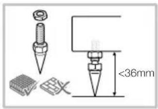
text_image
<36mm
text_image
<15mmnatural_image
Technical line drawing of a mechanical assembly with mounting brackets and alignment lines (no text or symbols)606 S3 / 607 S3
text_image
>0.5m 1.5m - 3m >0.5mtext_image
>0.5m 110° - 130° ~40°text_image
0.5m - 1m 0.5m - 1mtext_image
Technical diagram showing assembly of a bolt and nut assembly with labeled parts and a magnified inset view.Instalace reprosoustav
603 S3
natural_image
Simple line drawing of a Y-shaped object with a central conical feature and a circular arrow symbol at the base (no text or labels)
text_image
<36mm
text_image
<15mm
natural_image
Technical line drawing of a structural joint or bracket (no text or symbols)606 S3 / 607 S3
text_image
>0.5m 1.5m - 3m >0.5mtext_image
>0.5m 110° - 130° ~40°Domácí kino
text_image
0.5m - 1m 0.5m - 1mtext_image
Technical diagram showing assembly of a bolt and nut assembly with labeled parts and a magnified inset view.natural_image
Simple line drawing of a Y-shaped object with a central conical feature and a circular arrow symbol at the base (no text or labels)
text_image
<36mm
text_image
<15mm
natural_image
Technical line drawing of a mechanical assembly with no visible text or symbols606 S3 / 607 S3
text_image
>0.5m 1.5m - 3m >0.5mtext_image
>0.5m 110° - 130° ~40°Házimozi rendszerek
text_image
0.5m - 1m 0.5m - 1mtext_image
Technical diagram showing assembly of a bolt and nut assembly with labeled parts and a magnified inset view.Instalacja głośnika
603 S3
natural_image
Simple line drawing of a Y-shaped object with a central conical feature and a circular arrow symbol (no text or labels)
text_image
<36mm
text_image
<15mm
natural_image
Technical line drawing of a structural joint or bracket with mounting feet and connection points (no text or symbols)606 S3 / 607 S3
text_image
>0.5m 1.5m - 3m >0.5mtext_image
>0.5m 110° - 130° ~40°text_image
0.5m - 1m 0.5m - 1mtext_image
Technical diagram showing assembly of a bolt and nut assembly with labeled components and a magnified inset detail.Hoparlör Kurulumu
603 S3
natural_image
Simple line drawing of a Y-shaped object with a central conical feature and a circular arrow symbol at the base (no text or labels)
text_image
<36mm
text_image
<15mm
natural_image
Technical line drawing of a mechanical assembly with no visible text or symbols606 S3 / 607 S3
text_image
>0,5m 110° - 130° ~40°text_image
0.5m - 1m 0.5m - 1mManyetik Alan Paraziti
text_image
Technical diagram showing assembly of a bolt and nut assembly with labeled parts and a magnified inset view.扬声器安装
603 S3
natural_image
Simple line drawing of a Y-shaped object with a central conical feature and a circular arrow symbol (no text or labels)
text_image
<36mm
text_image
<15mm
要安全说明
钉脚尖锐,请勿触摸
natural_image
Technical line drawing of a mechanical assembly with mounting brackets and fasteners (no text or symbols)606 S3 / 607 S3
text_image
Technical diagram showing assembly of a bolt and nut assembly with labeled parts and a magnified inset view.揚聲器安裝
603 S3
natural_image
Simple line drawing of a Y-shaped object with a central conical feature and a circular arrow symbol at the base (no text or labels)
text_image
<36mm
text_image
<15mm
重要安全須知
尖銳釘腳,請勿觸摸。
natural_image
Technical line drawing of a mechanical assembly with mounting brackets and alignment lines (no text or symbols)606 S3 / 607 S3
text_image
>0.5m 1.5m - 3m >0.5m揚聲器定位
text_image
>0.5m 110° - 130° ~40°家庭影院系統
text_image
0.5m - 1m 0.5m - 1m雜散磁場
text_image
Technical diagram showing assembly of a bolt and nut assembly with labeled components and a magnified inset detail.スピーカーの設置
603 S3
natural_image
Simple line drawing of a Y-shaped object with a central conical feature and a circular arrow symbol (no text or labels)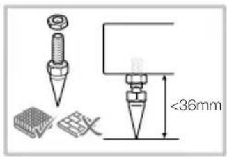
text_image
<36mm
text_image
<15mm
重要 安全上の注意
natural_image
Technical line drawing of a structural joint or bracket (no text or symbols)606 S3 / 607 S3
text_image
>0.5m 1.5m - 3m >0.5mスピーカー設置位置
text_image
>0.5m 110° - 130° ~40°
text_image
0.5m - 1m 0.5m - 1mホームシアターシステム
text_image
Technical diagram showing assembly of a bolt and nut assembly with labeled parts and a magnified inset view.스피커 설치
603 S3
natural_image
Simple line drawing of a Y-shaped object with a central conical feature and a circular arrow symbol at the base (no text or labels)
text_image
<36mm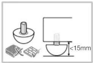
text_image
<15mm
중요한 안전 유의 사항
natural_image
Technical line drawing of a mechanical assembly with mounting brackets and alignment lines (no text or symbols)606 S3 / 607 S3
text_image
>0.5m 1.5m - 3m >0.5m스피커 배치
text_image
>0.5m 110° - 130° ~40°홈 시어터 시스템
text_image
0.5m - 1m 0.5m - 1m표유 자기장
Worthing West Sussex
BN11 2BH England
EU Importer:
Bowers & Wilkins
Beemdstraat 11
5653 MA Eindhoven
The Netherlands
Copyright © B&W Group Ltd. E&OE
