
CDA-16 - Speaker BOWERS & WILKINS - Free user manual and instructions
Find the device manual for free CDA-16 BOWERS & WILKINS in PDF.
| Product Type | 16-channel / 8-zone Class D distribution amplifier |
| Brand | Bowers & Wilkins |
| Model | CDA-16 |
| Dimensions (H x W x D) | 44.5 x 437 x 310 mm (without feet); 55.5 x 437 x 310 mm (with feet) |
| Net weight | 4.5 kg |
| Mains power | 100-240 V AC, 50/60 Hz |
| Power consumption | Standby < 0.5 W; operating max 300 W average, 1000 W peak |
| Output power per channel (4 Ω) | 100 W before clipping |
| Output power per channel (8 Ω) | 50 W before clipping |
| Bridged output power (8 Ω) | 200 W before clipping |
| Frequency response (-3 dB) | < 10 Hz to > 50 kHz |
| Signal-to-noise ratio (ref. 50 W / 8 Ω) | > 100 dB (A-weighted) |
| Total harmonic distortion (1 kHz, 12.5 W, 4 Ω) | Typically 0.05% |
| Maximum voltage gain | 34.9 dB |
| Input impedance | 15 kΩ |
| Signal detection threshold | 2.5 mV (independent of gain setting) |
| 12 V trigger threshold | 3 V (recommended 5 to 15 V) |
| Number of channels | 16 channels (8 stereo zones or 16 mono zones in bridge) |
| Input connectors | 8 RCA pairs (line); global input shared with zone 8 |
| Output connectors | 8 x Phoenix Combicon 4-pin 5.08 mm; 1 RCA pair global output |
| Power modes | Always on, auto-detect, 12 V trigger |
| Protections | Overload, short-circuit, thermal |
| Mounting | 19-inch 1U rack or on feet |
| Maintenance and cleaning | Disconnect the device before cleaning. Use a dry, soft cloth. Do not block ventilation openings. |
| Safety | Disconnect before any connection. Do not expose to moisture. Respect minimum impedances (4 Ω stereo, 8 Ω bridge). |
Frequently Asked Questions - CDA-16 BOWERS & WILKINS
User questions about CDA-16 BOWERS & WILKINS
0 question about this device. Answer the ones you know or ask your own.
Ask a new question about this device
Download the instructions for your Speaker in PDF format for free! Find your manual CDA-16 - BOWERS & WILKINS and take your electronic device back in hand. On this page are published all the documents necessary for the use of your device. CDA-16 by BOWERS & WILKINS.
USER MANUAL CDA-16 BOWERS & WILKINS
Welcome to Bowers & Wilkins and CDA-16
Thank you for choosing Bowers & Wilkins. When John Bowers first established our company, he did so in the belief that imaginative design, innovative engineering and advanced technology were keys that could unlock the enjoyment of audio in the home. His belief is one that we continue to share and inspires every product we design, tailored for new audio experiences outside of the home.
Our CDA-16 distribution power amplifier can drive any Bowers & Wilkins custom installation speaker to new heights of performance. Offering 16 channels of power, the CDA-16 can enable your whole home with sound yet takes up minimal space thanks to its compact 1U design. Its configurable specification supports bridging of its Class D stereo channels into even more powerful mono outputs, if needed.
Features
16 channels distribution amplification in 8 zones with a powerful 100 watts per channel to deliver high-resolution audio.
Engineered to work with any Bowers & Wilkins installation speakers.
- Highly flexible usage / configuration - Zone L/R outputs can be bridged to provide a mono output of double the power.
- Three power mode control options - on, auto detect or 12V trigger.
- Robust and reliable protection features, preventing damage due to overload, short circuits or heat.
- Ultra-compact rack-mount design (1 rack unit), easy to install and configure.
1.CDA-16 Carton Contents
1 x Power cable
2xRack-mountears
4 x Rack-mount ears screws
4xFeet
4 x Feet screws
8×5.08mm Pitch 4-way Phoenix Combicon style
2. Installation
2.1 Rack mounting
CDA-16 is intended to be installed in a standard 19-inch equipment rack. It is supplied with rack mount ears, but not rack mount bolts and nuts. Ensure that, once mounted in the rack, the amplifier is well ventilated and that the ventilation apertures are not obstructed. If the system is taken out of use for a long period, disconnect the amplifier from the mains power supply.
The CDA-16 is supplied with two rack mounting ears for installation in standard equipment racks. Attach the brackets by inserting machine screws through each bracket into the threaded holes in the side of the amplifier, see Diagram 2.

To prevent damage, maintain adequate ventilation space to the sides of the
amplifier.CDA-16 can be stacked vertically
but be sure not to place the amplifier next to other components, or against the side of a cabinet. Doing so will block ventilation openings.
2.2 Foot mounting
CDA-16 can also be table mounted and is supplied with feet and feet screws, see Diagram 3.
Ensure that, once positioned, the amplifier is well ventilated and that the ventilation apertures are not obstructed. If the system is taken out of use for a long period, disconnect the amplifier from the mains power supply.

To prevent damage, maintain adequate ventilation space to the sides of the
amplifier.CDA-16 can be stacked vertically
but be sure not to place the amplifier next to other components, or against the side of a cabinet. Doing so will block ventilation openings.
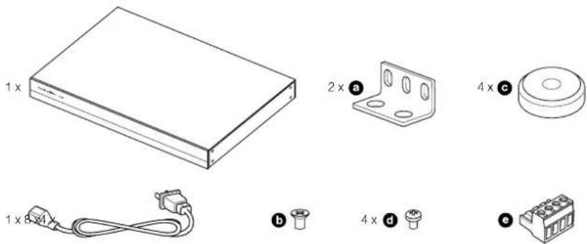
Diagram 1
Contents
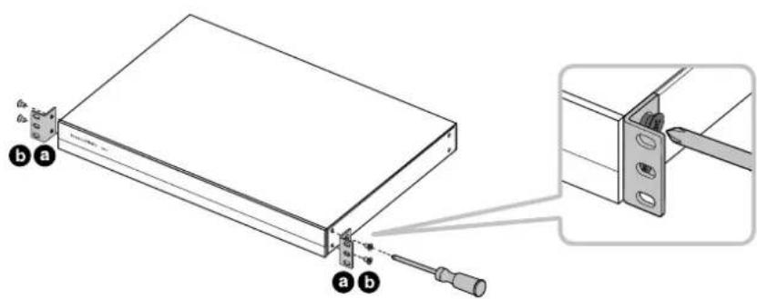
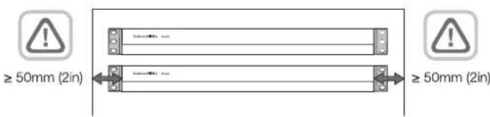
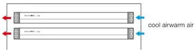
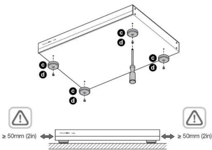
Diagram 2
Rack mounting
Diagram 3
Foot mounting
3. Controls and Connections
Rear panel sockets and switches
- Power input socket (IEC C14)
- Link to global input
- Bridge mode
- Power mode
- Zone outputs
- Zone 1-7 inputs
- Zone 8 input / Global in
8.Global out - 12 V trigger in / out
Front panel controls
- Power LED
- Zone status LEDs
4. Connecting

Connecting speaker wires or input cables while the amplifier is powered may cause electrical shock and could damage the. Unplug the power cord before making ons.
4.1 Connecting from source
CDA-16 accepts stereo line-level audio connections to its RCA Phono sockets. Each ZONE input will pass amplified audio to the respective zone speaker output. Alternatively, each ZONE can be linked individually to the GLOBAL IN (shared with ZONE 8).
- Connect the audio cable to the ZONE inputs (1-8) RCA Phono inputs, see Diagram 6
- (Optional) Connect the audio cable to GLOBAL IN (ZONE 8) and link speaker outputs to the GLOBAL IN by moving the dip switch up for that zone to the ON position.
4.2 Connecting to speakers
CDA-16 can power eight stereo zones of audio and has phoenix-style terminal blocks for speaker connections. Speakers can also be wired to bridge channels to increase the power available to the speakers.
To connect stereo speakers:
- Connect speaker cable to the phoenix connector and reinsert into the amplifier, see Diagram 7.

The common signal of these speaker outputs must not be connected together or to any other common signal. Do not
connect the L-and R-negative terminals together.Doing so will result in a fault condition and the amplifier will either shut down or not work properly.

Check the polarity of the speakers and wires before connecting to the amplifier.
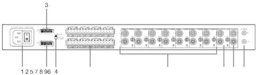
Diagram 4
Rear panel
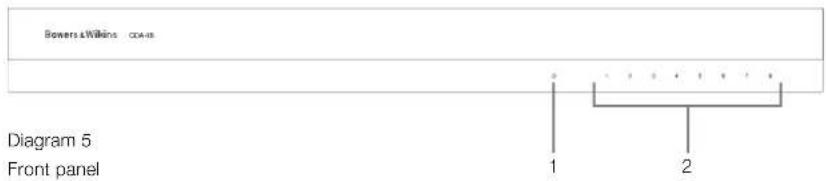

Diagram 6
Connecting from source

Diagram 7
Connecting to speakers
To connect bridged speakers, see Diagram 8:
- Set the BRIDGE MODE dip switch if needed for each zone by moving the dip switch up for that zone to the ON position.
- Connect + terminal from the speaker to the + terminal of the right channel (R).
- Connect the - terminal from the speaker to the - terminal of the left channel (L) on the amplifier.
The two terminals for a bridged pair of speakers area marked by ^+ BRIDGE-
In bridge mode both amplifiers in the zone combine to make a mono output of double the power. When in bridge mode only the left channel RCA input to the zone is active so please connect the input to this jack.
Note: The minimum load impedance in bridge mode is 8 . Connecting 4 loads may result in lower output power, distortion and overheating.
5. Setting POWER MODE
CDA-16 can be set up to automatically power on when needed. The POWER MODE switch, see Diagram 9, allows CDA-16 to be powered on at all times, turned on with a 12V trigger or turned on when an audio signal is present at any audio input.
To set up CDA-16 to be always on:
- Slide the POWER MODE switch to ON.
In this mode, CDA-16 will be always on unless the power cord is unplugged or the power switch by the power plug is toggled off.
To set up CDA-16 turn on by AUTO DETECT:
- Slide the POWER MODE switch to AUTO DETECT
In this mode, CDA-16 will turn on when an audio signal is sensed on the audio input.
Note: Only the amplifier zone that senses audio will turn on when in AUTO DETECT mode.
To set up CDA-16 to be controlled by a 12V trigger:
- Slide the POWER MODE switch to 12V TRIGGER.
- Connect the 12V trigger cable to the 3.5mm 12V TRIGGER IN jack socket, see Diagram 10.
- (Optional) Connect the 12V TRIGGER OUT jack socket to another amplifier to link their power control together.
In this mode, CDA-16 will turn on when a 12V signal is present on the 12V Trigger Input. This 12V trigger input can be wired to the 12V trigger output from an audio matrix switch or a relay.
Note: All amplifier zones turn on when a 12V trigger is received in 12V TRIGGER mode.
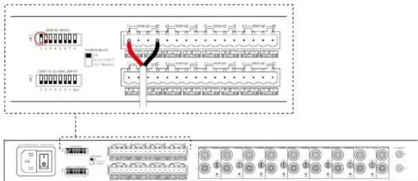
Diagram 8 Connecting bridged speakers

Diagram 9 Power mode switch

Diagram 10 Controlled by 12V trigger
6. GAIN Controls and CLIP Indicator
The GAIN controls are located next to each Zone input on the rear panel. They are operated by rotating the control clockwise to increase the GAIN or counter clockwise to decrease the GAIN. When turned fully counter clockwise, GAIN is reduced to 0 and no output signal will be present. When turned fully clockwise, the GAIN of the amplifier is +34.9dB.
To operate the GAIN control, rotate the control's knob so that the desired level is achieved, a small, flat-tipped screwdriver is typically used, see Diagram 11.
Note: Do not apply excessive torque to the control, it will turn easily unless at the ends of its travel
The CLIP indicator LED is located below the GAIN control. Flashing CLIP indicator indicates clipping is present while playing source input.
7. LED status
Power LED
LED Status
Dark / Unlit Off
Dim white Standby
White Or
Red PSU Fau
Zone status LED
LED Status
Dark / unlit Off / Signal not present / PSU fault
White On and signal present
Red Zone fault
8. Support
Should you require further help or advice regarding your CDA-16 please visit the support site here bowerswilkins.com/support.
Environmental Information
This product complies with international directives, including but not limited to the Restriction of Hazardous Substances (RoHS) in electrical and electronic equipment, the Registration, Evaluation, Authorisation and restriction of Chemicals (REACH) and the disposal of Waste Electrical and Electronic Equipment (WEEE). Consult your local waste disposal authority for guidance on how properly to recycle or dispose of this product.
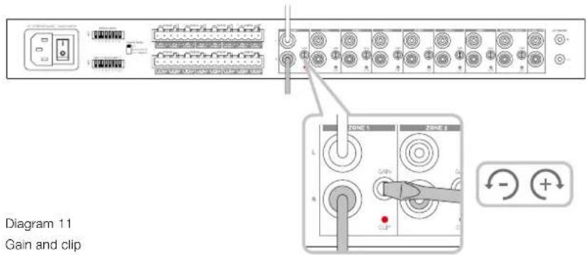
Diagram 12
LED status
Specifications
Audio Specifications
Load impedance range: >3 per channel (>6 in bridge mode)
50W into 8Ω
Output Power per channel, non-cipped: >100W into 4Ω
Output Power bridge mode, non-clipped: >200W into 8Ω
Output Power total, all channels: >400W short term
Output Power total, air channels. >200W continuous average
DC offset voltage: < 50mV
Frequency Response (-3dB): <10Hz to >50kHz, any load impedance
Frequency response accuracy 20Hz-20kHz: ±0.5dB
Signal to Noise ratio (Ref. 50W/8Ω): >100dB A-Weighted
THD+N (1kHz, 12.5W, 4Ω): typically 0.05%
Voltage Gain: 34.9dB to - infinity, adjustable
Input impedance: 15KΩ
Maximum input voltage: 6.8V peak (4.8V rms sine wave)
Signal sense threshold: 2.5mV (independent of Gain setting)
<0.2s (If other zones active) Wake-up time:
<2s (From all zones inactive)
Turn-off time: 15 minutes from last signal detected
12V trigger input threshold: typically 3V (recommended input is 5-15V)
Controls & Indicators
Front panel: 1 x Power LED (unit active - White, Fault - Red)
8 x Zone status LEDs (Signal present - White, Fault - Red)
Rear panel: 8 × 2 -position DIP switches (link to global input)
1 x 3-position switch (power mode: on, auto detect, 12V trigger)
8 x input gain control with Clip indicator LEDs
Connectors
Input: 8 x RCA (pair) Phono socket, line in (global in shared with Zone 8)
Output: 1 x RCA (pair) Phono socket (global out)
8×5.08mm Pitch 4-way Phoenix Combicon style
12V trigger control:
1 x 3.5 mm jack - 12V trigger IN
1 x 3.5 mm jack - 12V trigger OUT (Maximum 100mA pass-through)
Power
Power consumption: <0.5W All zones inactive
<45W All zones idling
300W maximum average
1,000W peak
AC supply:
100-240V 50/60Hz
AC inlet:
IEC C14, switched
Thermal
Thermal dissipation: 1.7 BTU/hr (standby),
150 BTU/hr (Idle),
400 BTU/hr (max)
Dimensions
Height: 44.5 mm (1.8 in) 1U [55.5 mm (2.2 in) plus feet]
Width: 437 mm (17.2 in)
Depth: 310 mm (12.2 in)
Net weight: 4.5kg (9.9lb)
Finish:
Black
Specifications audio
THD+Ruido(1kHz,12'5W,4Ω):0'05%
Altura: 44'5 mm 1U (55'5 mm mas pies)
Anchura: 437 mm
Profundidad: 310 mm
Peso neto: 4'5 kg
Acabado: negro
Para ligar as columnes estereo:
<45 W (todas as zonas inatas)
300 W de media maxima
1000 W pico
Potenied or used per cunlure, cenized clipping: >100 W a 4 Ω
- Voedings-LED
- Zonestatus-LED's
4. Aansluiten

Signal-ruisverholding (Ref. 50W/8Ω): >100dB A-gewogen
THD+N (1kHz, 12,5W, 4Ω): normaliter 0,05%
Spanningsversterking: 34,9dB tot oneindig, instelbaar
06m CnHn 3nX BxIOoB Ha ayCTNCHCKC CXCTOMb He DoJNCH COOHNATBCB MBCTe KIN C KAKIM-NOHO DpyrUMOBHMnHnONAM He CoeHNHnRE L
- nR-(otpuataeBbHc)KEMMBBmectc.3TO npmbetKHeCNCPaBHocTHN yCINNTELn60 OTKCHOTCA,HO He 6ydt paGobTb DONKHBMOBaPOM

PepelnpnOHeM KcIINTEIO npoepbTe npoJIHOCTb AkyCTmHECKNX CNTEM N npoBOOB.
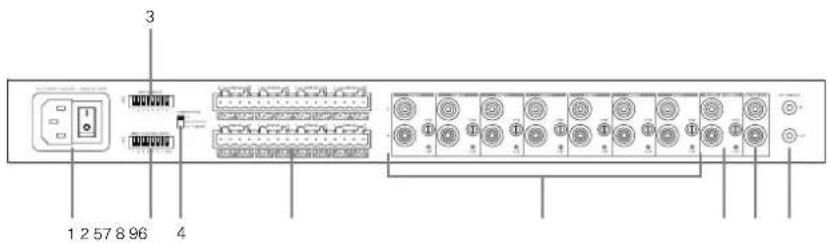
Diagram 4
3aHnnaHnB

Diagram 6
IopKJIIOUeHHe NCTOCHKO8
Diagram 7
PoiKIOUeHneAkyCtUueCKNX CNTEM
T06bI NOKIOHHTaKcYTHeCKMe CNTeMki MocTOBbIM BxOJAM, CM. Diagram 8:
1.YcTaHcBnTe DIP-nepeKIOHATeNB B pexkIM BRIDGE MODE,ecnn 3TO He6bXIOIIMO nn kXaKnO n30H,cDmHyB DIP-nepeKIOHATeNB Hepx dNnAToI O30Hb -B nonoXeHne ON.
2. NOKHIOHTe KJEMMy +01 OAKCTUeCKO cnTeMbIKKJEMMe++npaorOKaHana(R).
3. JIJIIOHTE KNIEMM YOTAKCYTHeCKOJ CNTeMbKKNEMMEBBOKAHana(L) cunnttna.
DBe KNeMBMbI MAnOToBn NapbI AkyCTNueCKNX CNTEM 063aHHeHbHKAO+BRIDGE-
BMOCTOBOMPEXMMOc6aYCUNITNEBA30HE
05EBMHNIOCTC,TTOBcSO3ADbMOHO-BBXOXUyBOEHHOH
MOUHOCN. BMOCTOBOMPEXMMAKTUBNETONKBO
BXOHDPOBEMRCAIEBBOFOKAHN30HbI,NGSTOMY
NOKANYCTa,NOKKNQHTeBXOHDCNTHANKSTOMy
pa3cbmy.
PnIMeHHe:MinHMaJIbHoe COpOuBHeHHe HAPy3K M MOCTOBOM PCXHMe pABHO 8 OM. IIOxKIOeHHe4-OMHOHARpy3M MoKetI PmBeCTN K CHUKeHNO BbXoHNO MOUHOCHT, NCKAeHNM INCPOrPCBy.
5.3aHaHnepeKmMaBKnIOueHnPOWER MODE
PnHc06xOgMnOCTnIyCynNtEeCA-16MOXHO 3aDaTbAIMOATNHCCO6BKNCHNCNITAHNA. PpeKcnHcTbE pKmIAPOW KPERMODE,CM.Diagram9, no36oJrrerCDA-16bblnoocToHHBOKKnOHeHHBM, nboBkNoHcyBaTcno12-B TpTTREPHOMy CnHany, NIO Bo BkNOHbChPiNIOINHmnyayINO CnTHAHAHIOBOM ayINO BXode.
YcunntbCDA-16BnBcerdaBknoeH
1.CBnHbTe npeknOHTeBPOWER MODE BIOJIOJEHN ON-BK.
B 3OM pexime CDA-16 6ydt Bcerda BkIkyeh,ecn TIOJIbKO HINPIHANH HEOTC0EJIHNHOT POeTKN IINBAI KIOUHTaNb NITNAHHE He BkIkyeh.
INABTOMATMNECKORBKNIOCHENCDA-16 npn 0bHApyKeHN ayDNO CNTHANHa HBXOe:
1.CBHHHEIpeKIOHOTeIbpeKIMPAOFWERMODE BNOPOXHEMEAUTODETECT.
B ATOM pexmme CDA-16 Bknoaetc npn noBneHn 3BykoBOO CnHnHa Ha ayDn BoXoe.
PpMmOaHm: BpcXmMo AUTO DETECTBkHouactcTOnToKTo30aYcHnTcTe,8KOTOPo6hApxKeH ayDmoCmHnH.
HaTropca CDA-16JnBkIyOeHn no 12-B TrrgEhomy cnHny:
1.CBnHbTe nepeKIOHOaTb poXmAPower MODE BNOJOxHeMe 12V TRIGGER.
2.ПОДСОЕДИНТe 12-BΚабьк паьemy3,5 MM 12V TRIGGER IN,cm.Diagram 10.
3.(Onu)CoOHNHTaKa6eHmpa5bcm12V TRIGGEROUTcaymuycuJIHEnE,Tc06bl C8B3A7xC0DHMN3anyCKaQmCNHAFOM
B 30m pexime CDA-16 BIOIOHCTIPIIIOAe
CINHana 12 BA hro TPRIRREPHB BXOD,12V Trigger
Input.30T 12 BTPRIRREPHB BXOD MOKET bHTb
PNOKINIKEN BHXOY 12 B0 MATPNHO aJIMN
KOMMYATOPaNN peJe.
PnmeHHeBc 30bY cInTeR bKIOHOATCR
IPO NIOyEHMM Tprrrephoro CmHAn 12 B a
peXMe 12VTRIGGER.

Diagram 8 PIOKJIQUeHHe KOHOK Ha MoCTOBO BbXoD
Diagram 9 Ipeeknoaeta b POWER MODE
6. PerynpobKo300nmeHOB ycnHeNn GAIN n Hdkatop KnnnpobAnn CLIP
OpraHbpeynpaKn KQdPhiMHTOcynHeHnGAIN
paONoXeHbPdOM CO BXoDM KAKdoN 3030n ZOn
Ha aadHnAHE. OH npyapnIOTC BpAHHEM
perYrTopa nO cacoBn CTpeKn Dn yBEHNHe
ycnHeHnGAIN INn pOtnHB VACOBn CTpeKNn Dn
ymEhBHeHn.PnIOHOM NOBOPTe PNTABuOBO
CTpeKN KooΦmHnEYTcNHeHn YMeHNbAETCRNo 0
HNIHKAKOFBO XbDOHOrO CINHnA He ByET.PnNlHOM
noopote No cacoBn CTpeKne GAIN ycInnter
coctaaBert+34,9D5
IpynpaKn yonneHn noBopaHnBaTe pyknyTak, 06b6 b6o3yEe HcBnAeMn npoeBb, 06bHNO nCnO3yEe HeBnAeN OtePkn CnOckm u
PmmeHHe:He npnraeTepeSmeHoeYcwnne K orany ynpaehn, OH nKro nobopaaeeTcN oka HeocptnaeTynopa H KOJax cO XoJa.
HnDkKatop KINNNPBOAHN (OgpanHueHH
CnHana) pacnooxch nod pcnyrnapoym cunHnna.
Mraaoi nnHcKatop kAsbHaHa Ha To, 10o Bpema
BocpnosaeHHxOHO HorO CnHHe OT daHOrO
HCtoTHNka PPOCXDGHT OPAHNUCHNC CnHnA No
AMNTUYte.
7.CBToDnOHyIeLEDHnKAtOpbl COCTOHHN
HdkaTop nntaan Power LED
HdkkaTop ctaTyca 30n Zone LED
CBeueHHe LED Ctatyc 30hbl
| TeMHbI / He ropHT | Off - BykHcHeyHa/ CnHana Het/ OTKa3 6nKa 1nTahmPSU |
| BénbI On - BkHcHey H nCtB CnHana | |
| KpaHbI OTKa3 3oHbI |
8.Подперхka
EcnBAMOTp6byTcDonONHtEnbHaN NOMOu HnCOEBOTOHCCTeBbHOBaWeroYcNtEnCDA-1G, NOXAKySWCTA, NOCEETeCAITNOpeKKnNo apeccy: bowerswilkins.com/support.
3KoIoruuecka HOpMaun
OTnpOdyKT COOTBCTBYCT MxDyHapOdbIM
DnepKTHNBM, BKNIOHA, HO Hc OPAHNHBARbC
OrpAHmEHm ONaChbX BeueCTB (Restriction of
Hazardous Substances - RoHS) B anckTpyeCKOM u
AnekTPOHHom o6opyoBaHm, pcrntpaunu, ouchke,
AbotPMAHm u or paHnEHm HA mOlsBOAHwe
XMMHcckXs BceCTB (REACH) ydaneHcno OTxODB
anckTpyeCKOR n ankTPOHoro o6opyoBaHn
(WEEE). PpokOHcyIbnyIpyTeCb C bIIMM MeHTbHM
opAHON noYtINMaZnn OTOxOB dnn ONYeHn
pOKOMhDaun o TOM, KAK PpABJIbHO pCNUKIpObaTb
nIyIyIm3pOBAbTB 10 npOxyd.
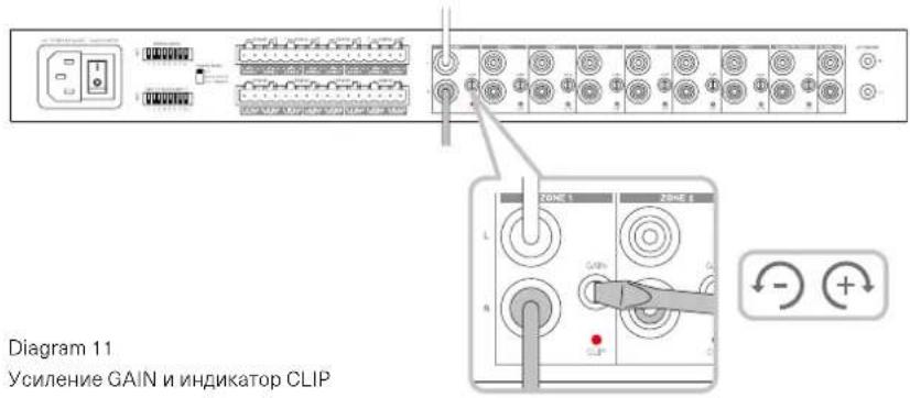

Diagram 11
YcJIeHnE GAIN n HnDnKaTOp CLIP
Diagram 12
HdkaTOp cTaYca
Texnueckne xapaKtepncTkn
Cekuaaydno
IMnepaHc Harpy3Ku: >3 OM Ha KaHaan (6 OM B MoCTOBOM pexmme)
BbXIOHARMOUHOCTb HA KAHAN,63KNIINNPOBAHIN: >50BTHa8OM 100RtH4O
BixOHaH MaUHOCTb B MoCTOBOM pEXIMe,63 KININPOBaHn: >200BT Ha 8 OM
CymmaHbBbXoHbMaOIOHOCTb,BO BcEx KaHaiJax: >400Bt,KpAeKOBpeMeHHa
CmeueHne no noct. TKy: <50 MB
Дианэанчсот(-3дБ):<10Hz->50kHz, npn liobom mmeaHce Harpy3kn
HepaBHOmePocbTbactoTHoX-Kn(20Γu-20Ku): ±0.5n6
OTHOeHnCnHn/UmOTH.50BT/8OM) >100bA-B3BwU
VckaeHnTHD+N(1KtU,12.5BT,4OM):0.05%TNHHBte
YcunneHnno HanpXeHHIO: 34.9D5 - infinity, perynpyemoe
BxodnoH mmepaHc: 15 KOm
MaKc. BxOJHoe HAnpXeHHe: 6.8 B nuk (4.8 B rms nIycondAnbHoro cunHana)
Topor obHapyxeHnCnHa: 2.5 MB (He 3aBucnt OytcTaHOBKn Gain)
Bnem 1006xHnH 0.2 cek (ecnn npyne 3Ohbl aKTNBHbI)
<2 cek (ecn npyme 30hI He aKTHBbl)
BpemrdoABTO-OTKIOHHeHn:15MnOHOTnoCneHero CnHaHa
Iopor 12-B Tprrrephoro cnHana: 3 B-TnHHbI (peKoMeHdyTeTcA 5-15 B)
OprahbI ynpaBneHn m HndkaTOpbl
Пеледя naelb: 1x Power LED (aktden-H White,otka3 - Red)
8xLEDctatyczane(Ectbcurhan-White,otka3-Red)
3aHnraHnB:8x2-103uOnHHbIXDIPnepeKIOHateLeiCBBaTio6abHbIMBXoDM)
1x3-n0nHnHHnnepeKnHnateB (peKm BkNoeHn: on, auto detect, 12V trigger)
8xperyIITOpOB yCmIeHn cLED mDkKatopAMn CLIP
Pa3beMbl
BxOy:8 x RCA (nap), mH. BxOy (rno6abnBnBnBnBnO6i n C Zone 8)
IopTe6JIeHHe: <0.5BT npn He aKTHBbIX BCEx 3OHX
<45BT-Bce30HbHaX.X.
300BT,MAKc.cpeHHa
1,000Bt.nukobar
HannpaeHne cetn AC:
100-240 B 50/60Hz
Pazbem nntanrAC inlet:
IEC C14, KOMMMyTnpyEmbl
TenIOBBie XapaKTepuCTnKu
TennobdeneHne: 1.7 BTU/uc (Bstandby),
150 BTU/4ac (Ha x.x.),
400 BTU/aca (MaKc.)
Pa3Mepbl
BbICota: 44.5 MM (1.8 in) 1U [55.5 MM (2.2 in) nIOc onopbl]
山nina: 437MM(17.2in)
Iiyubina: 310MM(12.2in)
Bec, HeTTo: 4.5 Kr (9.9 lb)
Ottena: Yepna - Black
KaIomegaopioate otnv Bowers & Wilkins kaI to CDA-16
Zac euxapotoue nou eilaleate tny Bowers & Wilkins. O John Bowers iDpuoe Tnv etaepia mac e Tnv npiolthon oti n eufavtaoTn oxdeltaon, naivotouia otnv avantuEkn kai n Eeliyevn texvooyia thav ta klaedia ton ou aavoivay vouc koouc anolauonc tou nxou oTo OTt. Autnv tnv niotn tou ouvexizoue va moipacómaote kai eurvei kaTe poiov nou oxdeltaoue, npoaapuoemv ny avec nhtikec eptic ektoiou.
O evioutn oixuoc diavounc CDA-16 mnpei va ftoa onoiobnte nxio 16 kavaia oxuoc nou npoospei, to CDA-16 mnpei va diavemu xo ooloknpo to ontit oac, alambda kataaumabve iexalxoto xwp, xapn ot nikpu u e theouc oxdeltaon 1U. Oiaopphiouc npodaypaec tou unootnpiouv tn yepwon twpoeoowkuv kavaiwv Katnyopiac D nou dtaetie aka pio ixupce movofomegakec eodouc, avival apaitntto.
Xapaktnpiotiká
Ondstrup signal / Šum (Ref. 50W/8Ω): >100dB A-Weighted
THD+N(1kHz,12.5W,4Ω):Bézné 0.05%
7. Statusy diody LED
Statusy Diody LED zasilania
LED Status