DWS727 - Saw DEWALT - Free user manual and instructions
Find the device manual for free DWS727 DEWALT in PDF.
Download the instructions for your Saw in PDF format for free! Find your manual DWS727 - DEWALT and take your electronic device back in hand. On this page are published all the documents necessary for the use of your device. DWS727 by DEWALT.
USER MANUAL DWS727 DEWALT
WARNING: Read all safety warnings, instructions, illustrations
and specifications provided with this power tool. Failure to follow all instructions listed below may result in electric shock, fire and/or serious injury.
WARNING: To reduce the risk of injury, read the
instructionmanual. Definitions: Safety Guidelines The definitions below describe the level of severity for each signal word. Please read the manual and pay attention to thesesymbols.
DANGER: Indicates an imminently hazardous situation which, if not
avoided, will result in death or seriousinjury.
WARNING: Indicates a potentially hazardous situation which, if not
avoided, could result in death or seriousinjury.
CAUTION: Indicates a potentially hazardous situation which, if not avoided, may result in minor or moderateinjury. NOTICE: Indicates a practice not related to personal injury which, if not avoided, may result in propertydamage.
Denotes risk of electricshock.
Denotes risk offire. The vibration and/or noise emission level given in this information sheet has been measured in accordance with a standardised test given in EN62841 and may be used to compare one tool with another. It may be used for a preliminary assessment ofexposure.
WARNING: The declared vibration and/or noise emission level
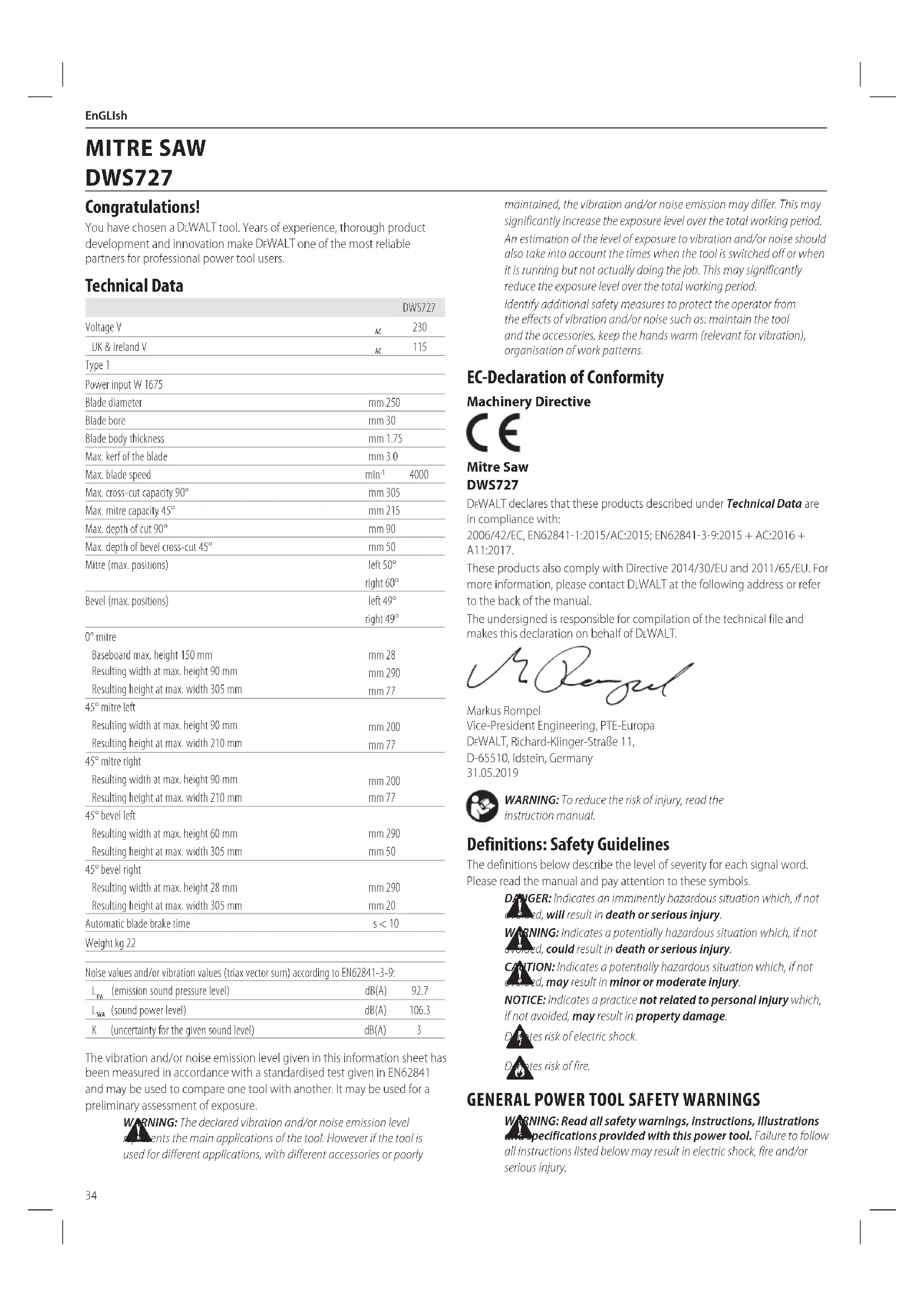
represents the main applications of the tool. However if the tool is used for different applications, with different accessories or poorly maintained, the vibration and/or noise emission may differ. This may significantly increase the exposure level over the total workingperiod. An estimation of the level of exposure to vibration and/or noise should also take into account the times when the tool is switched off or when it is running but not actually doing the job. This may significantly reduce the exposure level over the total workingperiod. Identify additional safety measures to protect the operator from the effects of vibration and/or noise such as: maintain the tool and the accessories, keep the hands warm (relevant for vibration), organisation of workpatterns. EC-Declaration of Conformity Machinery Directive Mitre Saw DWS727 DeWALT declares that these products described under Technical Data are in compliance with: 2006/42/EC, EN62841-1:2015/AC:2015; EN62841-3-9:2015 + AC:2016 + A11:2017. These products also comply with Directive 2014/30/EU and 2011/65/EU. For more information, please contact DeWALT at the following address or refer to the back of themanual. The undersigned is responsible for compilation of the technical file and makes this declaration on behalf of DeWALT
(emission sound pressure level) dB(A) 92.7
(sound power level) dB(A) 106.3 K (uncertainty for the given sound level) dB(A) 3 Congratulations! You have chosen a DeWALT tool. Years of experience, thorough product development and innovation make DeWALT one of the most reliable partners for professional power toolusers. Technical Data English (original instructions) MITRE SAW DWS72735 EnGLIsh Safety Instructions for Mitre Saws a ) Mitre saws are intended to cut wood or wood-like products, they cannot be used with abrasive cut-off wheels for cutting ferrous material such as bars, rods, studs, etc. Abrasive dust causes moving parts such as the lower guard to jam. Sparks from abrasive cutting will burn the lower guard, the kerf insert and other plasticparts. b ) Use clamps to support the workpiece whenever possible. If supporting the workpiece by hand, you must always keep your hand at least 100mm from either side of the saw blade. Do not use this saw to cut pieces that are too small to be securely clamped or held by hand. If your hand is placed too close to the saw blade, there is an increased risk of injury from bladecontact. c ) The workpiece must be stationary and clamped or held against both the fence and the table. Do not feed the workpiece into the blade or cut “freehand” in any way. Unrestrained or moving workpieces could be thrown at high speeds, causinginjury. d ) Push the saw through the workpiece. Do not pull the saw through the workpiece. To make a cut, raise the saw head and pull it out over the workpiece without cutting, start the motor, press the saw head down and push the saw through the workpiece. Cutting on the pull stroke is likely to cause the saw blade to climb on top of the workpiece and violently throw the blade assembly towards theoperator. e ) Never cross your hand over the intended line of cutting either in front or behind the saw blade. Supporting the workpiece “cross handed” i.e. holding the workpiece to the right of the saw blade with your left hand or vice versa is verydangerous.
SAVE ALL WARNINGS AND INSTRUCTIONS
FOR FUTURE REFERENCE. The term “power tool” in the warnings refers to your mains-operated (corded) power tool or battery-operated (cordless) powertool.
a ) Keep work area clean and well lit. Cluttered or dark areas inviteaccidents. b ) Do not operate power tools in explosive atmospheres, such as in the presence of flammable liquids, gases or dust. Power tools create sparks which may ignite the dust orfumes. c ) Keep children and bystanders away while operating a power tool. Distractions can cause you to losecontrol.
2) Electrical Safety
a ) Power tool plugs must match the outlet. Never modify the plug in any way. Do not use any adapter plugs with earthed (grounded) power tools. Unmodified plugs and matching outlets will reduce risk of electricshock. b ) Avoid body contact with earthed or grounded surfaces, such as pipes, radiators, ranges and refrigerators. There is an increased risk of electric shock if your body is earthed orgrounded. c ) Do not expose power tools to rain or wet conditions. Water entering a power tool will increase the risk of electricshock. d ) Do not abuse the cord. Never use the cord for carrying, pulling or unplugging the power tool. Keep cord away from heat, oil, sharp edges or moving parts. Damaged or entangled cords increase the risk of electricshock. e ) When operating a power tool outdoors, use an extension cord suitable for outdoor use. Use of a cord suitable for outdoor use reduces the risk of electricshock. f ) If operating a power tool in a damp location is unavoidable, use a residual current device (RCD) protected supply. Use of an RCD reduces the risk of electricshock.
a ) Stay alert, watch what you are doing and use common sense when operating a power tool. Do not use a power tool while you are tired or under the influence of drugs, alcohol or medication. A moment of inattention while operating power tools may result in serious personalinjury. b ) Use personal protective equipment. Always wear eye protection. Protective equipment such as dust mask, non-skid safety shoes, hard hat or hearing protection used for appropriate conditions will reduce personalinjuries. c ) Prevent unintentional starting. Ensure the switch is in the off- position before connecting to power source and/or battery pack, picking up or carrying the tool. Carrying power tools with your finger on the switch or energising power tools that have the switch on invitesaccidents. d ) Remove any adjusting key or wrench before turning the power tool on. A wrench or a key left attached to a rotating part of the power tool may result in personalinjury. e ) Do not overreach. Keep proper footing and balance at all times. This enables better control of the power tool in unexpectedsituations. f ) Dress properly. Do not wear loose clothing or jewellery. Keep your hair and clothing away from moving parts. Loose clothes, jewellery or long hair can be caught in movingparts. g ) If devices are provided for the connection of dust extraction and collection facilities, ensure these are connected and properly used. Use of dust collection can reduce dust-relatedhazards. h ) Do not let familiarity gained from frequent use of tools allow you to become complacent and ignore tool safety principles. A careless action can cause severe injury within a fraction of asecond.
4) Power Tool Use and Care
a ) Do not force the power tool. Use the correct power tool for your application. The correct power tool will do the job better and safer at the rate for which it wasdesigned. b ) Do not use the power tool if the switch does not turn it on and off. Any power tool that cannot be controlled with the switch is dangerous and must berepaired. c ) Disconnect the plug from the power source and/or remove the battery pack, if detachable, from the power tool before making any adjustments, changing accessories, or storing power tools. Such preventive safety measures reduce the risk of starting the power toolaccidentally. d ) Store idle power tools out of the reach of children and do not allow persons unfamiliar with the power tool or these instructions to operate the power tool. Power tools are dangerous in the hands of untrainedusers. e ) Maintain power tools and accessories. Check for misalignment or binding of moving parts, breakage of parts and any other condition that may affect the power tool’s operation. If damaged, have the power tool repaired before use. Many accidents are caused by poorly maintained powertools. f ) Keep cutting tools sharp and clean. Properly maintained cutting tools with sharp cutting edges are less likely to bind and are easier tocontrol. g ) Use the power tool, accessories and tool bits etc. in accordance with these instructions, taking into account the working conditions and the work to be performed. Use of the power tool for operations different from those intended could result in a hazardoussituation. h ) Keep handles and grasping surfaces dry, clean and free from oil and grease. Slippery handles and grasping surfaces do not allow for safe handling and control of the tool in unexpectedsituations.
a ) Have your power tool serviced by a qualified repair person using only identical replacement parts. This will ensure that the safety of the power tool is maintained.36 EnGLIsh f ) Do not reach behind the fence with either hand closer than 100mm from either side of the saw blade, to remove wood scraps, or for any other reason while the blade is spinning. The proximity of the spinning saw blade to your hand may not be obvious and you may be seriouslyinjured. g ) Inspect your workpiece before cutting. If the workpiece is bowed or warped, clamp it with the outside bowed face toward the fence. Always make certain that there is no gap between the workpiece, fence and table along the line of the cut. Bent or warped workpieces can twist or shift and may cause binding on the spinning saw blade while cutting. There should be no nails or foreign objects in theworkpiece. h ) Do not use the saw until the table is clear of all tools, wood scraps, etc., except for the workpiece. Small debris or loose pieces of wood or other objects that contact the revolving blade can be thrown with highspeed. i ) Cut only one workpiece at a time. Stacked multiple workpieces cannot be adequately clamped or braced and may bind on the blade or shift duringcutting. j ) Ensure the mitre saw is mounted or placed on a level, firm work surface before use. A level and firm work surface reduces the risk of the mitre saw becomingunstable. k ) Plan your work. Every time you change the bevel or mitre angle setting, make sure the adjustable fence is set correctly to support the workpiece and will not interfere with the blade or the guarding system. Without turning the tool “ON” and with no workpiece on the table, move the saw blade through a complete simulated cut to assure there will be no interference or danger of cutting thefence. l ) Provide adequate support such as table extensions, saw horses, etc. for a workpiece that is wider or longer than the table top. Workpieces longer or wider than the mitre saw table can tip if not securely supported. If the cut-off piece or workpiece tips, it can lift the lower guard or be thrown by the spinningblade. m ) Do not use another person as a substitute for a table extension or as additional support. Unstable support for the workpiece can cause the blade to bind or the workpiece to shift during the cutting operation pulling you and the helper into the spinningblade. n ) The cut-off piece must not be jammed or pressed by any means against the spinning saw blade. If confined, i.e. using length stops, the cut-off piece could get wedged against the blade and thrownviolently. o ) Always use a clamp or a fixture designed to properly support round material such as rods or tubing. Rods have a tendency to roll while being cut, causing the blade to “bite” and pull the work with your hand into theblade. p ) Let the blade reach full speed before contacting the workpiece. This will reduce the risk of the workpiece beingthrown. q ) If the workpiece or blade becomes jammed, turn the mitre saw off. Wait for all moving parts to stop and disconnect the plug from the power source and/or remove the battery pack. Then work to free the jammed material. Continued sawing with a jammed workpiece could cause loss of control or damage to the mitresaw. r ) After finishing the cut, release the switch, hold the saw head down and wait for the blade to stop before removing the cut-off piece. Reaching with your hand near the coasting blade isdangerous. s ) Hold the handle firmly when making an incomplete cut or when releasing the switch before the saw head is completely in the down position. The braking action of the saw may cause the saw head to be suddenly pulled downward, causing a risk ofinjury. Additional Safety Rules for Mitre Saws
WARNING: Do not connect to the mains power supply into the unit
until complete instructions are read andunderstood.
- DO NOT OPERATE THIS MACHINE until it is completely assembled and installed according to the instructions. A machine incorrectly assembled can cause seriousinjury.
- OBTAIN ADVICE from your supervisor, instructor, or another qualified person if you are not thoroughly familiar with the operation of this machine. Knowledge issafety.
- MAKE CERTAIN the blade rotates in the correct direction. The teeth on the blade should point in the direction of rotation as marked on thesaw.
- TIGHTEN ALL CLAMP HANDLES, knobs and levers prior to operation. Loose clamps can cause parts or the workpiece to be thrown at highspeeds.
- BE SURE all blade and blade clamps are clean, recessed sides of blade clamps are against blade and arbour screw is tightened securely. Loose or improper blade clamping may result in damage to the saw and possible personalinjury.
- DO NOT OPERATE ON ANYTHING OTHER THAN THE DESIGNATED VOLTAGE for the saw. Overheating, damage to the tool and personal injury mayoccur.
- DO NOT WEDGE ANYTHING AGAINST THE FAN to hold the motor shaft. Damage to tool and possible personal injury mayoccur.
- NEVER CUT METALS or masonry. Either of these can cause the carbide tips to fly off the blade at high speeds causing seriousinjury.
- NEVER HAVE ANY PART OF YOUR BODY IN LINE WITH THE PATH OF THE SAW BLADE. Personal injury willoccur.
- NEVER APPLY BLADE LUBRICANT TO A RUNNING BLADE. Applying lubricant could cause your hand to move into the blade resulting in seriousinjury.
- DO NOT place either hand in the blade area when the saw is connected to the power source. Inadvertent blade activation may result in seriousinjury.
- NEVER REACH AROUND OR BEHIND THE SAW BLADE. A blade can cause seriousinjury.
- DO NOT REACH UNDERNEATH THE SAW unless it is unplugged and turned off. Contact with saw blade may cause personalinjury.
- SECURE THE MACHINE TO A STABLE SUPPORTING SURFACE. Vibration can possibly cause the machine to slide, walk, or tip over, causing seriousinjury.
- USE ONLY CROSSCUT SAW BLADES recommended for mitre saws. For best results, do not use carbide tipped blades with hook angles in excess of 7 degrees. Do not use blades with deep gullets. These can deflect and contact the guard, and can cause damage to the machine and/or seriousinjury.
- USE ONLY BLADES OF THE CORRECT SIZE AND TYPE specified for this tool to prevent damage to the machine and/or serious injury (complying with EN847-1).
- INSPECT BLADE FOR CRACKS or other damage prior to operation. A cracked or damaged blade can come apart and pieces can be thrown at high speeds, causing serious injury. Replace cracked or damaged blades immediately. Observe the maximum speed marked on the sawblade.
- THE MAXIMUM SPEED OF THE SAW BLADE shall always be greater than or at least equal to the speed marked on the rating plate of the tool.
- THE SAW BLADE DIAMETER must be in accordance with the markings on rating plate of the tool.
- CLEAN THE BLADE AND BLADE CLAMPS prior to operation. Cleaning the blade and blade clamps allows you to check for any damage to the blade or blade clamps. A cracked or damaged blade or blade clamp can come apart and pieces can be thrown at high speeds, causing seriousinjury.37 EnGLIsh Markings on Tool The following pictograms are shown on the tool: Read instruction manual beforeuse. Package Contents The package contains: 1 Assembled mitre saw 1 Blade wrench (assembled on the saw) 1 Saw blade(assembled on the saw) 1 Material clamp 2 Base extensions 2 Screws 2 Washers 1 Instruction manual
- Check for damage to the tool, parts or accessories which may have occurred duringtransport.
- Take the time to thoroughly read and understand this manual prior tooperation. Electrical Safety The electric motor has been designed for one voltage only. Always check that the power supply corresponds to the voltage on the rating plate. Your DeWALT tool is double insulated in accordance with EN62841; therefore no earth wire is required.
WARNING: 115 V units have to be operated via a fail-safe isolating
transformer with an earth screen between the primary and secondary winding. If the supply cord is damaged, it must be replaced only by DeWALT or an authorised serviceorganisation. Mains Plug Replacement (U.K. & Ireland Only) If a new mains plug needs to be fitted:
- Safely dispose of the oldplug.
- Connect the brown lead to the live terminal in theplug.
- Connect the blue lead to the neutralterminal.
WARNING: No connection is to be made to the earthterminal.
Follow the fitting instructions supplied with good quality plugs. Recommended fuse: 13A. Using an Extension Cable If an extension cable is required, use an approved 3–core extension cable suitable for the power input of this tool (see Technical Data).The minimum conductor size is 1.5 mm
; the maximum length is 30 m. When using a cable reel, always unwind the cablecompletely.
WARNING: We recommend the use of a residual current device with a
residual current rating of 30mA orless. Residual Risks The following risks are inherent to the use of saws:
- Injuries caused by touching the rotatingparts. In spite of the application of the relevant safety regulations and the implementation of safety devices, certain residual risks cannot be avoided. These are:
- Impairment ofhearing.
- Risk of accidents caused by the uncovered parts of the rotating sawblade.
- Risk of injury when changing theblade.
- Risk of squeezing fingers when opening theguards.
- Health hazards caused by breathing dust developed when sawing wood, especially oak, beech andMDF. The following factors increase the risk of breathing problems:
- No dust extractor connected when sawingwood.
- Insufficient dust extraction caused by uncleaned exhaustfilters.
SAVE THESE INSTRUCTIONS
- DO NOT USE WARPED BLADES. Check to see if the blade runs true and is free from vibration. A vibrating blade can cause damage to the machine and/or seriousinjury.
- DO NOT use lubricants or cleaners (particularly spray or aerosol) in the vicinity of the plastic guard. The polycarbonate material used in the guard is subject to attack by certainchemicals.
- KEEP GUARD IN PLACE and in workingorder.
- ALWAYS USE THE KERF PLATE AND REPLACE THIS PLATE WHEN DAMAGED. Small chip accumulation under the saw may interfere with the saw blade or may cause instability of workpiece whencutting.
- USE ONLY BLADE CLAMPS SPECIFIED FOR THIS TOOL to prevent damage to the machine and/or seriousinjury.
- MAKE SURE to use the correct saw blade for the material to becut.
- CLEAN THE MOTOR AIR SLOTS of chips and sawdust. Clogged motor air slots can cause the machine to overheat, damaging the machine and possibly causing a short which could cause seriousinjury.
- NEVER LOCK THE SWITCH IN THE “ON” POSITION. Severe personal injury mayresult.
- NEVER STAND ON TOOL. Serious injury could occur if the tool is tipped or if the cutting tool is unintentionallycontacted.
WARNING: Cutting plastics, sap coated wood, and other materials
may cause melted material to accumulate on the blade tips and the body of the saw blade, increasing the risk of blade overheating and binding whilecutting.
WARNING: Always wear proper personal hearing protection.
Under some conditions and duration of use, noise from this product may contribute to hearing loss. Be aware of the following factors influencing exposure to noise:
- Use saw blades designed to reduce the emitted noise,
- Use only well sharpened saw blades, and
- Use specifically designed noise-reduction sawblades.
WARNING: ALWAYS use safety glasses. Everyday eyeglasses are NOT
safety glasses. Also use face or dust mask if cutting operation isdusty.
WARNING: Use of this tool can generate and/or disperse dust, which
may cause serious and permanent respiratory or otherinjury.
WARNING: Some dust created by power sanding, sawing, grinding,
drilling, and other construction activities contains chemicals known to cause cancer, birth defects or other reproductive harm. Some examples of these chemicals are:
- lead from lead-based paints,
- crystalline silica from bricks and cement and other masonry products, and
- arsenic and chromium from chemically-treatedlumber. Your risk from these exposures varies, depending on how often you do this type of work. To reduce your exposure to these chemicals: work in a well ventilated area, and work with approved safety equipment, such as those dust masks that are specially designed to filter out microscopicparticles.
- Avoid prolonged contact with dust from power sanding, sawing, grinding, drilling, and other construction activities. Wear protective clothing and wash exposed areas with soap and water. Allowing dust to get into your mouth, eyes, or lay on the skin may promote absorption of harmfulchemicals.
WARNING: Use of this tool can generate and/or disperse dust, which
may cause serious and permanent respiratory or other injury. Always use approved respiratory protection appropriate for the dustexposure.38 ENGLISH
ASSEMBLY AND ADJUSTMENTS
WARNING: To reduce the risk of serious personal injury, turn
tool off and disconnect tool from power source before making any adjustments or removing/installing attachments or accessories. An accidental start-up can causeinjury. Unpacking (Fig. A1,F)
1. Open the box and lift the saw out by the con venient carrying handle
as shown in FigureF.
2. Place the saw on a smooth, flatsurface.
3. Release the rail lock knob
, and push the saw head back to lock it in the rearposition.
4. Press down lightly on the operating handle
and pull out the lock down pin
5. Gently release the downward pressure and hold the operating handle,
allowing it to rise to its fullheight. Bench Mounting (Fig. A1) Holes
are provided in all four feet to facilitate bench mounting. Two different-sized holes are provided to accommodate different sizes of screws. Use either hole; it is not necessary to useboth. Always mount your saw firmly to a stable surface to prevent movement. To enhance the tool’s portability, it can be mounted to a piece of 12.7 mm or thicker plywood which can then be clamped to your work support or moved to other job sites andreclamped. NOTE: If you elect to mount your saw to a piece of plywood, make sure that the mounting screws don’t protrude from the bottom of the wood. The plywood must sit flush on the work support. When clamping the saw to any work surface, clamp only on the clamping bosses where the mounting screw holes are located. Clamping at any other point will interfere with the proper operation of thesaw.
CAUTION: To prevent binding and inaccuracy, be sure the mounting surface is not warped or otherwise uneven. If the saw rocks on the surface, place a thin piece of material under one saw foot until the saw sits firmly on the mountingsurface. Assembling the Base Extensions (Fig. Y)
WARNING: Base extensions must be assembled to both sides of
the saw's base before using thesaw.
WARNING: Be sure to adjust the base extensions using the
mounting slots so they are level with the saw'sbase.
1. Locate the holes above the hand indentations
on the side of thebase.
2. Using the supplied wrench or a T30 wrench, attach the screw
, through the base extension
, and into the holes on thebase.
3. Ensure the extension is secure by pulling on the extension to verify
4. Repeat steps 1 through 3 on the otherside.
Changing or Installing a New Saw Blade Removing the Blade (Fig. G1–G4)
WARNING: To reduce the risk of injury, wear gloves when handling
WARNING: To reduce the risk of injury, turn unit off and
disconnect machine from power source before installing and Description (Fig. A1–E)
WARNING: Never modify the power tool or any part of it. Damage or
personal injury couldresult. Fig. A1
Rail set screw adjustment
Fence adjustment knob
Base extension/carry handle
Bench mounting holes
Depth adjustment screw
DE7025-XJ Clamp brackets Intended Use Your DeWALT DWS727 mitre saw has been designed for professional cutting of wood, wood products and plastics. When using the appropriate saw blades, sawing aluminium is also possible. It performs the sawing operations of cross-cutting, bevelling and mitring easily, accurately andsafely. DO NOT use under wet conditions or in the presence of flammable liquids orgases. This mitre saw is a professional powertool. DO NOT let children come into contact with the tool. Supervision is required when inexperienced operators use thistool. Date Code Position (Fig. A) The date code
, which also includes the year of manufacture, is printed into thehousing. Example: 2019 XX XX Year of Manufacture Wear earprotection. Wear eyeprotection. Keep hands away fromblade. Visible radiation. Do not stare intolight.
- Young children and the infirm. This appliance is not intended for use by young children or infirm persons withoutsupervision.
- This product is not intended for use by persons (including children) suffering from diminished physical, sensory or mental abilities; lack of experience, knowledge or skills unless they are supervised by a person responsible for their safety. Children should never be left alone with thisproduct.39 EnGLIsh removing accessories, before adjusting or changing set-ups or when making repairs. Be sure the trigger switch is in the OFF position. An accidental start-up can causeinjury.
- Never depress the spindle lock button while the blade is under power orcoasting.
- Do not cut light alloy and ferrous metal (containing iron or steel) or masonry or fibre cement product with this mitresaw.
2. Raise the arm to the upper position and raise the lower guard
while carefully rotating the saw blade by hand until the lockengages.
4. Keeping the button depressed, use the other hand and the wrench
to loosen the blade screw
5. Remove the blade screw
may be left on thespindle.
6. Remove and retain the adaptor ring
from the old blade in case it is needed when installing a newblade. Installing a Blade (Fig. G1–G4)
into the hole of the new saw blade ifnecessary.
3. With the arm raised and the lower guard
held open, mount the blade onto the shoulder of the inner washer
, making sure the teeth at the bottom of the blade point toward the back of thesaw.
4. Assemble the outer clamp washer onto thespindle.
5. Install the blade screw and, engaging the spindle lock, tighten the
screw firmly with wrench provided (turn counterclockwise, left- handthreads).
WARNING! Be aware the saw blade shall be replaced in the described way only. Only use saw blades as specified under Technical Data; Cat. no.: DT4260 issuggested. Transporting the Saw (Fig. A1, A2)
WARNING: To reduce the risk of serious personal injury,
ALWAYS lock the rail lock knob, mitre lock handle, bevel lock handle, lock down pin and fence adjustment knobs before transporting saw. Never use guards for transporting or liftingup. In order to conveniently carry the mitre saw, a carrying handle
has been included on the top of the sawarm.
- To transport the saw, lower the head and depress the lock down pin
- Lock the rail lock knob with the saw head in the front position, lock the mitre arm in the full left mitre angle, slide the fence
completely inward and lock the bevel lock knob
with the saw head in the vertical position to make the tool as compact aspossible.
- Always use the carrying handle
Features and Controls
WARNING: To reduce the risk of injury, turn unit off and
disconnect machine from power source before installing and removing accessories, before adjusting or changing set-ups or when making repairs. Be sure the trigger switch is in the OFF position. An accidental start-up can causeinjury. Mitre Control (Fig.A1, H) The mitre lock handle
downward. To exit the override, push the mitre detent overrideupward. Bevel Lock Knob (Fig. A2) The bevel lock allows you to bevel the saw 49° left or right. To adjust the bevel setting, turn the bevel lock knob
counterclockwise. The saw head bevels easily to the left or to the right once the 0° bevel override knob is pulled. To tighten, turn the bevel lock knobclockwise. 0° Bevel Override (Fig. A2) The 0° bevel stop
override allows you to bevel the saw to the right past the 0°mark. When engaged, the saw will automatically stop at 0° when brought up from the left. To temporarily move past 0° to the right, pull the bevel lock knob
. Once the knob is released, the override will be reengaged. The bevel lock knob can be locked out by twisting the knob 180°. When at 0°, the override locks in place. To operate the override, bevel the saw slightly to theleft. 45° Bevel Stop Override (Fig.I) There are two bevel stop override levers, one on each side of the saw. To bevel the saw, left or right, past 45°, push the 45° bevel override lever
rearward. When in the rearward position, the saw can bevel past these stops. When the 45° stops are needed, pull the 45° bevel override leverforward. Crown Bevel Pawls (Fig.I) When cutting crown molding laying flat, your saw is equipped to accurately and rapidly set a crown stop, left or right (refer to Instructions for Cutting Crown Molding Laying Flat and Using the Compound Features) The crown bevel pawl
can be rotated to contact the crown adjustmentscrew. To reverse the crown bevel pawl, remove the retaining screw, the 22.5° bevel pawl
and the 30° crown bevel pawl
so the 30° text is facing up. Reattach the screw to secure the 22.5° bevel pawl and the crown bevel pawl. The accuracy setting will not beaffected. 22.5° Bevel Pawls (Fig.I) Your saw is equipped to rapidly and accurately set a 22.5° bevel, left or right. The 22.5° bevel pawl
can be rotated to contact the crown adjustment screw
allows you to lock the saw head firmly to keep it from sliding on the rails
allows the depth of cut of the blade to be limited. The stop is useful for applications such as grooving and tall vertical cuts. Rotate the grooving stop forward and adjust the depth adjustment screw
to set the desired depth of cut. To secure the adjustment, tighten the wing nut
. Rotating the grooving stop to the rear of the saw will bypass the grooving stop feature. If the depth adjustment screw is too tight to loosen by hand, the provided blade wrench
can be used to loosen thescrew. Lock Down Pin (Fig. A1)
WARNING: The lock down pin should be used only when
carrying or storing the saw. NEVER use the lock down pin for any cuttingoperation. To lock the saw head in the down position, push the saw head down, push the lock down pin
in and release the saw head. This will hold the saw head safely down for moving the saw from place to place. To release, press the saw head down and pull the pinout.40 ENGLISH Slide Lock Lever (Fig. J, T) The slide lock lever
places the saw in a position to maximize cutting of base moulding when cut vertically as shown in FigureT. Right-Hand Flip Down Stop (Fig. A1, A2) The right-hand flip down stop
is mounted on the sliding fence
and can be rotated backward when not needed. When cutting multiple pieces at the same width, rotate the right-hand flip down stop forward, move out the sliding fence to the required distance from the blade (to be measured by a ruler) and with the wood board facing against the stop make thecut. Adjustment Your mitre saw is fully and accurately adjusted at the factory at the time of manufacture. If readjustment due to shipping and handling or any other reason is required, follow the instructions below to adjust your saw. Once made, these adjustments should remainaccurate. Mitre Scale Adjustment (Fig.H, K)
locks it at the 0° mitre position. Do not lock the mitre lockhandle.
2. Place a square against the saw’s fence and blade, as shown. (Do not
touch the tips of the blade teeth with the square. To do so will cause an inaccurate measure ment.)
3. If the saw blade is not exactly perpendicular to the fence, loosen the
and move the mitre lock handle and the scale left or right until the blade is perpendicular to the fence, as measured with thesquare.
4. Retighten the four screws. Pay no attention to the reading of the mitre
at thistime. Mitre Pointer Adjustment (Fig.H)
to move the mitre arm to the zeroposition.
2. With the mitre lock handle unlocked, allow the mitre latch to snap into
place as you rotate the mitre arm tozero.
shown in FigureH. If the pointer does not indicate exactly zero, loosen the mitre pointer screw
holding the pointer in place, reposition the pointer and tighten thescrew. Bevel Square to Table Adjustment (Fig.A1, A2,I,L)
1. To align the blade square to the table, lock the arm in the down
position with the lock down pin
2. Place a square against the blade, ensuring the square is not on top of a
and ensure the arm is firmly against the 0° bevelstop.
4. Rotate the 0° bevel adjustment screw (
Fig. I) with the 6mm blade wrench
as necessary so that the blade is at 0° bevel to thetable. Bevel Pointer Adjustment (Fig.I) If the bevel pointers
that holds each bevel pointer in place and move them as necessary. Ensure the 0° bevel is correct and the bevel pointers are set before adjusting any other bevel anglescrews. Bevel Stop 45° Right and Left Adjustment (Fig.A2,I) To adjust the right 45° bevel stop:
to the full out position before beveling thesaw.
and pull the 0° bevel stop
3. When the saw is fully to the right, if the bevel pointer
does not indicate exactly 45°, turn the left 45° bevel adjustment screw
with the 6 mm blade wrench
to the full out position before beveling thesaw.
2. Loosen the bevel lock knob and tilt the head to theleft.
3. If the bevel pointer does not indicate exactly 45°, turn the right 45°
bevel adjustment screw until the bevel pointer reads 45°. Adjusting the Bevel Stop to 22.5° (or 30°) (Fig.A2, I) NOTE: Adjust the bevel angles only after performing the 0° bevel angle and bevel pointeradjustment. Slide the sliding fences to the full out position before starting the 22.5° or 30° beveladjustment. To set the left 22.5° bevel angle, flip out the left 22.5° bevel pawl
and tilt the head fully to the left. If the bevel pointer
does not indicate exactly 22.5°, turn the crown adjustment screw
contacting the pawl with a 10 mm wrench until the bevel pointer reads 22.5°. To adjust the right 22.5° bevel angle, flip out the right 22.5° bevel pawl. Loosen the bevel lock knob and pull the 0° bevel stop
to override the 0° bevel stop. When the saw is fully to the right, if the bevel pointer does not indicate exactly 22.5°, turn the crown adjustment screw
contacting the pawl with a 10 mm wrench until the bevel pointer indicates exactly 22.5°. Fence Adjustment (Fig. A1) The upper part of the fence can be adjusted to provide clearance, allowing the saw to bevel to a full 49° both left andright.
1. To adjust each fence
, loosen the fence adjustment knob
and slide the fenceoutward.
2. Make a dry run with the saw turned off and check forclearance.
3. Adjust the fence to be as close to the blade as practical to provide
maximum workpiece support, without interfering with arm up and downmovement.
4. Tighten the fence adjustment knobsecurely.
5. When the bevel operations are complete, relocate thefence.
NOTE: The tracks of the fences can become clogged with sawdust. Use a brush or some low pressure air to clear the guidegrooves. Guard Actuation and Visibility (Fig. X) The lower guard
on your saw has been designed to automatically uncover the blade when the arm is brought down and to cover the blade when the arm israised. The guard can be raised by hand when installing or removing saw blades or for inspection of the saw. NEVER RAISE THE lower GUARD MANUALLY UN LESS THE BLADE ISSTOPPED. Rail Guide Adjustment (Fig. A1) Regularly check the rails
for play orclearance. The left rail can be adjusted with the set screw
. To reduce clearance, use a 4 mm hex wrench and rotate the set screw clockwise gradually while sliding the saw head back andforth. Mitre Lock Adjustment (Fig. A1, M) The mitre lock rod
should be adjusted if the table of the saw can be moved when the mitre lock handle is locked (down).
in the unlocked (up)position.
2. Using a slotted screwdriver, tighten the mitre lock rod by turning it
clockwise as shown in FigureM. Turn the lock rod until it is snug, then turn counterclockwise oneturn.
3. Re-lock the mitre lock to a non-detented measurement on the mitre
scale – for example, 34° – and make sure the table will notrotate. Prior to Operation
- Install the appropriate saw blade. Do not use excessively worn blades. The maximum rotation speed of the tool must not exceed that of the saw blade. Do not use any abrasiveblades.
- Check protective belt cover
for damage and proper functioning of lower guard
ENGLISH Refer to Saw Blades under Optional Accessories to select the blade that best fits yourneeds. Ensure the machine is placed to satisfy your ergonomic conditions in terms of table height and stability. The machine site shall be chosen so that the operator has a good overview and enough free surrounding space around the machine that allows handling of the workpiece without anyrestrictions. To reduce effects of vibration make sure the environment temperature is not too cold, the machine and accessories are well maintained and the workpiece size is suitable for thismachine. Plug the saw into any household 50 Hz power source. Refer to the nameplate for voltage. Be sure the cord will not interfere with yourwork. Proper Body and Hand Position (Fig. N1, N2)
WARNING: To reduce the risk of serious personal injury, ALWAYS use
proper hand position as shown in FigureN1.
WARNING: To reduce the risk of serious personal injury, ALWAYS hold
securely in anticipation of a suddenreaction.
- Never place hands near cutting area. Place hands no closer than 100 mm from theblade.
- Hold the workpiece tightly to the table and the fence when cutting. Keep hands in position until the trigger has been released and the blade has completelystopped.
- ALWAYS MAKE DRY RUNS (UNPOWERED) BEFORE FINISH CUTS SO THAT YOU CAN CHECK THE PATH OF THE BLADE. DO NOT CROSS HANDS, AS SHOWN IN FIGUREN2.
- Keep both feet firmly on the floor and maintain proper balance. As you move the mitre arm left and right, follow it and stand slightly to the side of the sawblade.
- Sight through the guard louvers when following a pencilline. Trigger Switch (Fig.A2) To turn the saw on, push the lock-off lever
to the left, then depress the trigger switch
. The saw will run while the switch is depressed. Allow the blade to spin up to full operating speed before making the cut. To turn the saw off, release the switch. Allow the blade to stop before raising the saw head. There is no provision for locking the switch on. A hole
is provided in the trigger for insertion of a padlock to lock the switchoff. Your saw is not equipped with an automatic electric blade brake, but the saw blade should stop within 10 seconds of trigger release. This is not OPERATION Instructions for Use
WARNING:Always observe the safety instructions and
applicableregulations.
WARNING:To reduce the risk of serious personal injury, turn
tool off and disconnect tool from power source before making any adjustments or removing/installing attachments or accessories. An accidental start-up can cause injury. adjustable. If the stop time repeatedly exceeds 10 seconds, have the tool serviced by an authorised DeWALT servicecentre. Always be sure the blade has stopped before removing it from thekerf. Dust Extraction (Fig.A2, C, Z)
WARNING: To reduce the risk of serious personal injury, turn
tool off and disconnect tool from power source before making any adjustments or removing/installing attachments or accessories. An accidental start-up can causeinjury.
WARNING: Certain dust, such as oak or beech dust, is considered
carcinogenic, especially in connection with wood-treatmentadditives.
- Always use dustextraction.
- Provide for good ventilation of the workspace.
- It is recommended to wear an appropriaterespirator.
CAUTION: Never operate this saw unless the dust bag or DeWALT dust extractor is in place. Wood dust may create a breathinghazard.
CAUTION: Check and clean the dust bag each time afterusing.
disconnect the dust extractor to avoid the risk offire. Your mitre saw has a built-in dust port
that allows connection to either the dust bag
, 33mm nozzles or direct attachment to the DeWALT
AirLock(DWV9000-XJ). Observe the relevant regulations in your country for the materials to beworked. To Attach the Dust Bag (Fig. C)
as shown in FigureC. To Empty the Dust Bag (Fig. C)
from the saw and gently shake or tap the dust bag toempty.
You may notice that all the dust will not come free from the bag. This will not affect cutting performance but will reduce the saw's dust collection efficiency. To restore your saw's dust collection efficiency, depress the spring inside the dust bag when you are emptying it and tap it on the side of the trash can or dustreceptacle. External Dust Extraction (Fig. Z) When vacuuming dry dust that is especially detrimental to health or carcinogenic, use a special dust Class M vacuumcleaner. Connecting to an AirLock Compatable Dust Extractor (Fig.Z) The dust port
on your mitre saw is compatable with the D
WALT AirLock connection system. The AirLock allows for a fast, secure connection between the dust extractor hose
1. Ensure the collar on the AirLock connector
is in the unlock position. Align notches
on collar and AirLock connector as shown for unlock and lockpositions.
3. Rotate the collar to the lockedposition.
NOTE: The ball bearings inside collar lock into slot and secure the connection.The mitre saw is now securely connected to the dustextractor. Use of XPS™ LED Worklight System (Fig. A1, A2) NOTE: The mitre saw must be connected to a powersource. The XPS™ LED Worklight System is equipped with an on/off switch
The XPS™ LED Worklight System is independent of the mitre saw’s trigger switch. The light does not need to be on in order to operate thesaw. To cut through an existing pencil line on a piece of wood:
1. Turn on the XPS™ system, then pull down on the operating handle
to bring the saw blade close to the wood. The shadow of the blade will appear on thewood.
- Install the table extensions to both sides of the saw's base. Refer to Assembling the Table Extensionssection.
- Do not attempt to cut excessively smallpieces.
- Allow the blade to cut freely. Do notforce.
- Allow the motor to reach full speed beforecutting.
- Make sure all locking knobs and clamp handles aretight.
- Secure theworkpiece.
- Although this saw will cut wood and many nonferrous materials, these operating instructions refer to the cutting of wood only. The same guidelines apply to the other materials. Do not cut ferrous (iron and steel) materials, fibre cement or masonry with this saw!
- Make sure to use the kerf plate. Do not operate the machine if the kerf slot is wider than 12mm.
- Connect saw to external an dustextractor.42 ENGLISH
2. Align the pencil line with the edge of the blade’s shadow. You may
have to adjust the mitre or bevel angles in order to match the pencil lineexactly. Through-Cutting Operations (Fig. A1, A2,O,P) If the slide feature is not used, ensure the saw head is pushed back as far as possible and the rail lock knob
is tightened. This will prevent the saw from sliding along its rails as the workpiece isengaged. Cutting of multiple pieces is not recommended but can be done safely by ensuring that each piece is held firmly against the table andfence. Straight Vertical Crosscut
1. Set and lock the mitre arm at zero, and hold the wood firmly on the
and against the fence
2. With the rail lock knob
tightened, turn on the saw by pushing the lock-off lever
and squeezing the trigger switch
3. When the saw comes up to speed, lower the arm smoothly and slowly
to cut through the wood. Let the blade come to a full stop before raisingarm. Sliding Crosscut (Fig. O) When cutting anything larger than a 51 x 115mm (51 x 82mm at 45° mitre) workpiece, use an out-down-back motion with the rail lock knob
loosened. Pull the saw out toward you, lower the saw head down toward the workpiece, and slowly push the saw back to complete thecut. Do not allow the saw to contact the top of the workpiece while pulling out. The saw may run toward you, possibly causing personal injury or damage to theworkpiece. Mitre Crosscut (Fig. P) The mitre angle is often 45° for making corners, but can be set anywhere from zero to 50° left or 60° right. Proceed as for a straight verticalcrosscut. When performing a mitre cut on workpieces wider than 51 x 105mm that are shorter in length, always place the longer side against thefence. Bevel Cut (Fig. A1, A2) Bevel angles can be set from 49° right to 49° left and can be cut with the mitre arm set between 50° left or 60° right. Refer to the Features and Controls section for detailed instructions on the bevelsystem.
, and move the saw to the left or right as desired. It is necessary to move the fence
to allow clearance. Tighten the fence adjustment knob
after positioning thefences.
2. Tighten the bevel lockfirmly.
At some extreme angles, the right side fence might have to be removed. Refer to Fence Adjustment in the Adjustments section for important information on adjusting the fences for certain bevelcuts. To remove the right fence, unscrew the fence adjustment knob
several turns and slide the fenceout. The right fence is secured to the base with a lanyard to prevent it from beinglost. Quality of Cut The smoothness of any cut depends on a number of variables, such as the material being cut, blade type, blade sharpness and rate ofcut. When smoothest cuts are desired for molding and other precision work, a sharp (60 tooth carbide) blade and a slower, even cutting rate will produce the desiredresults.
WARNING: Ensure that the material does not move or creep while
cutting; clamp it securely in place. Always let the blade come to a full stop before raising arm. If small fibres of wood still split out at the rear of the workpiece, stick a piece of masking tape on the wood where the cut will be made. Saw through the tape and carefully remove tape whenfinished. Non-Through-Cutting (Grooving and Rabbeting) (Fig. A2) Your saw is equipped with a grooving stop
, depth adjustment screw
to allow for groovecutting. Instructions in the Crosscuts, Bevel Cuts and Cutting Compound Mitres sections are for cuts made through the full thickness of the material. The saw can also perform non-through cuts to form grooves or rabbets in thematerial. Grooving (Fig. A1, A2) Refer to Grooving Stop for detailed instructions for setting depth of cut. A piece of scrap wood should be used to verify the desired depth ofcut.
1. Hold the wood firmly on the table and against the fence
. Align the cut area underneath the blade. Position the saw arm fully forward, with blade in down position. Turn on the saw by pushing the lock off- lever
and squeezing the trigger switch
. Smoothly, push saw arm rearward to cut a groove through the workpiece.
2. Release the trigger switch with the saw arm down. When saw blade has
completely stopped, raise the saw arm. Always let the blade come to a full stop before raising thearm.
3. To widen the groove, repeat steps 1–2 until the desired width
isobtained. Clamping the Workpiece (Fig.B)
WARNING: A workpiece that is clamped, balanced and secure
before a cut may become unbalanced after a cut is completed. An unbalanced load may tip the saw or anything the saw is attached to, such as a table or workbench. When making a cut that may become unbalanced, properly support the workpiece and ensure the saw is firmly bolted to a stable surface. Personal injury mayoccur.
WARNING: The clamp foot must remain clamped above the base of
the saw whenever the clamp is used. Always clamp the workpiece to the base of the saw – not to any other part of the work area. Ensure the clamp foot is not clamped on the edge of the base of thesaw.
CAUTION: Always use a work clamp to maintain control and reduce the risk of personal injury and workpiecedamage. Use the material clamp
provided with your saw. The left or right fence will slide from side to side to aid in clamping. Other aids such as spring clamps, bar clamps or C-clamps may be appropriate for certain sizes and shapes ofmaterial. To Install Clamp
1. There are four rectangular clamp mounting holes
in the base, two in the front and two on the back of the saw under the base fence. Insert the clamp
into one of the fourholes. NOTE: When assembling the clamp on the back side of the saw, the arm of the clamp will need to be at the highest position so that clamp post can be slid into the mounting hole as the clamp passes over thefence.
2. Loosen the knob to adjust the clamp up or down, tighten the knob to
to extend the table width of your saw. Support long workpieces using any convenient means such as sawhorses or similar devices to keep the ends fromdropping.43 EnGLIsh Cutting Picture Frames, Shadow Boxes And Other Four-Sided Projects (Fig.Q, R) Try a few simple projects using scrap wood until you develop a “feel” for your saw. Your saw is the perfect tool for mitring corners like the one shown in FigureQ. Sketch 1 in FigureR shows a joint made with the bevel adjustment method. The joint shown can be made using eithermethod.
- Using bevel adjustment: - The bevel for the two boards is adjusted to 45° each, producing a 90°corner. - The mitre arm is locked in the zero position and the bevel adjustment is locked at 45°. - The wood is positioned with the broad flat side against the table and the narrow edge against thefence.
- Using mitre adjustment: - The same cut can be made by mitring right and left with the broad surface against thefence. Cutting Trim Molding and Other Frames (Fig.R) Sketch 2 in FigureR shows a joint made by setting the mitre arm at 45° to mitre the two boards to form a 90° corner. To make this type of joint, set the bevel adjustment to zero and the mitre arm to 45°. Once again, position the wood with the broad flat side on the table and the narrow edge against thefence. The two sketches in FigureR are for four-sided objects only. As the number of sides changes, so do the mitre and bevel angles. The chart below gives the proper angles for a variety of shapes, assuming that all sides are of equallength. NUMBER OF SIDES MITRE OR BEVEL ANGLE 4 45° 5 36° 6 30° 7 25.7° 8 22.5° 9 20° 10 18° For a shape that is not shown in the chart, use the following formula: 180° divided by the number of sides equals the mitre (if the material is cut vertically) or bevel angle (if the material is cut layingflat). Cutting Compound Mitres (Fig.S) A compound mitre is a cut made using a mitre angle and a bevel angle at the same time. This is the type of cut used to make frames or boxes with slanting sides like the one shown in FigureS.
WARNING: If the cutting angle varies from cut to cut, check that the
bevel lock knob and the mitre lock handle are securely locked. These must be locked after making any changes in bevel ormitre. The chart shown below will assist you in selecting the proper bevel and mitre settings for common compound mitrecuts. Set this miter angle on saw Angle of side of box (angle ”A”) Set this bevel angle on saw
- Select the desired angle A (Fig.S) of your project and locate that angle on the appropriate arc in thechart.
- From that point follow the chart straight down to find the correct bevel angle and straight across to find the correct mitreangle.
- Set your saw to the prescribed angles and make a few trial cuts. Practise fitting the cut piecestogether. EXAMPLE: To make a 4-sided box with 26° exterior angles (Angle A, Fig.S), use the upper right arc. Find 26° on the arc scale. Follow the horizontal intersecting line to either side to get mitre angle setting on saw (42°). Likewise, follow the vertical intersecting line to the top or bottom to get the bevel angle setting on the saw (18°). Always try cuts on a few scrap pieces of wood to verify the settings on thesaw. Cutting Base Moulding (Fig.J, T) To complete straight 90° cuts, position the wood against the fence and hold it in place as shown in FigureT. Turn on the saw, allow the blade to reach full speed and lower the arm smoothly through thecut. Cutting Base Moulding from 70 mm up to 150 mm High Vertically Against the Fence (Fig. J, T) nOTE: Use the slide lock lever
, shown in FigureJ, when cutting base moulding measuring from 70 mm to 150 mm high vertically against thefence. Position material as shown in FigureT. All cuts should be made with the back of the moulding against the fence and with the bottom of the moulding against thetable. Inside Corner Outside Corner Left side Mitre left 45° Save left side of cut Mitre right 45° Save left side of cut Right side Mitre right 45° Save right side of cut Mitre left 45° Save right side of cut Material up to 150 mm can be cut as described above. Cutting Crown Moulding (Fig. A1, U1, U2) Your mitre saw is well suited to the task of cutting crown moulding. In order to fit properly, crown moulding must be compound mitred with extremeaccuracy. Your mitre saw has special pre-set mitre latch points at 22.5°, 31.6° and 35.3° left and right for cutting crown moulding at the proper angle and bevel stop pawls at 22.5° and 30° left and right. There is also a mark on 7 sIDED BOX 5 sIDED BOX sQUARE BOX44 ENGLISH Before use, carefully check the upper guard, lower guard and dust duct to determine that they will operate properly. Ensure that chips, dust or workpiece particles do not block of one of thefunctions. In case of workpiece fragments jammed between the saw blade and guards, disconnect the machine from the power supply and follow the instructions given in Changing or Installing a New Saw Blade. Remove the jammed parts and reassemble the sawblade. Periodically clean all dust and wood chips from around AND UNDER the base and the rotarytable. Worklight Cleaning
- Carefully clean sawdust and debris from worklight lens with a cotton swab. Dust build-up can block the worklight and prevent it from accurately indicating the line ofcut.
- DO NOT use solvents of any kind; they may damage thelens.
- With blade removed from saw, clean pitch and build-up fromblade. Dust Duct Cleaning With the saw unplugged and the saw head raised fully, low pressure air or a large diameter dowel rod can be used to clear the dust out of the dustduct. Cleaning
WARNING: Blow dirt and dust out of the main housing with dry air
as often as dirt is seen collecting in and around the air vents. Wear approved eye protection and approved dust mask when performing thisprocedure.
WARNING: Never use solvents or other harsh chemicals for cleaning
the non-metallic parts of the tool. These chemicals may weaken the materials used in these parts. Use a cloth dampened only with water and mild soap. Never let any liquid get inside the tool; never immerse any part of the tool into aliquid. Lubrication Your power tool requires no additionallubrication. MAINTENANCE Your power tool has been designed to operate over a long period of time with a minimum of maintenance. Continuous satisfactory operation depends upon proper tool care and regularcleaning.
WARNING:To reduce the risk of serious personal injury, turn
tool off and disconnect tool from power source before making any adjustments or removing/installing attachments or accessories. An accidental start-up can cause injury. the bevel scale
at 33.9°. The chart below gives the proper settings for cutting crownmoulding. NOTE: Pretesting with scrap material is extremely important! Instructions for Cutting Crown Moulding Laying Flat and Using the Compound Features (Fig. U1)
1. Moulding should lay flat with the broad back surface down on the
2. Place the top of the moulding against the fence
3. The settings below are for 45° sprung crownmoulding.
Inside Corner Outside Corner Left side Bevel left 30° Mitre table set at right 35.26° Save left end of cut Bevel right 30° Mitre table set at left 35.26° Save left end of cut Right side Bevel right 30° Mitre table set at left 35.26° Save right end of cut Bevel left 30° Mitre table set at right 35.26° Save right end of cut
4. The settings below are for crown moulding with 52° angles at the top
and 38° angles at thebottom. Inside Corner Outside Corner Left side Bevel left 33.9° Mitre table set at right 31.62° Save left end of cut Bevel right 33.9° Mitre table set at left 31.62° Save left end of cut Right side Bevel right 33.9° Mitre table set at left 31.62° Save right end of cut Bevel left 33.9° Mitre table set at right 31.62° Save right end of cut Alternative Method for Cutting Crown Moulding Cutting crown moulding using this method does not require a bevel cut. Minute changes in the mitre angle can be made without affecting the bevel angle. When corners other than 90° are encountered, the saw can be quickly and easily adjusted forthem. Instructions for Cutting Crown Moulding Angled Between the Fence and Base of the Saw for All Cuts (Fig. U2)
1. Angle the moulding so the bottom of the moulding (the part which
goes against the wall when installed) is against the fence
and the top of the moulding is resting on the saw table
2. The angled “flats” on the back of the moulding must rest squarely on
the fence and sawtable. Inside Corner Outside Corner Left side Mitre right at 45° Save right side of cut Mitre left at 45° Save right side of cut Right side Mitre left at 45° Save left side of cut Mitre right at 45° Save left side of cut Special Cuts
WARNING: Never make any cut unless the material is secured
on the table and against thefence. Aluminum Cutting (Fig. V1, V2) ALWAYS USE THE APPROPRIATE SAW BLADE MADE ESPECIALLY FOR CUTTINGALUMINUM. Certain workpieces may require the use of a clamp or fixture to prevent movement during the cut. Position the material so that you will be cutting the thinnest cross section, as shown in FigureV1. FigureV2 illustrates the wrong way to cut theseextrusions. Use a stick wax cutting lubricant when cutting aluminum. Apply the stick wax directly to the saw blade
before cutting. Never apply stick wax to a moving blade. The wax provides proper lubrication and keeps chips from adhering to theblade. Bowed Material (Fig. W1, W2) When cutting bowed material always position it as shown in FigureW1 and never like that shown in FigureW2. Positioning the material incorrectly will cause it to pinch theblade. Cutting Plastic Pipe or Other Round Material Plastic pipe can be easily cut with your saw. It should be cut just like wood and CLAMPED OR HELD FIRMLY TO THE FENCE TO KEEP IT FROM ROLLING. This is extremely important when making anglecuts. Cutting Large Material (Fig.X) Occasionally you will encounter a piece of wood a little too large to fit beneath the lower guard. If this occurs, place your right thumb on the upper side of the guard
and roll the guard up just enough to clear the workpiece, as shown in FigureX. Avoid doing this as much as possible, but if need be, the saw will operate properly and make the bigger cut. NEVER TIE, TAPE, OR OTHERWISE HOLD THE GUARD OPEN WHEN OPERATING THISSAW.45 ENGLISH Protecting the Environment Separate collection. Products marked with this symbol must not be disposed of with normal householdwaste. Products contain materials that can be recovered or recycled reducing the demand for raw materials. Please recycle electrical products according to local provisions. Further information is available at www.2helpU.com. Clamp: DW7090-XJ (Fig. B) The clamp
is used for firmly clamping workpiece to the sawtable. Quick Release Clamps: DWS5026-XJ Dust Bag: DW7053-QZ (Fig. C) Equipped with a zipper for easy emptying, the dust bag
are used for mounting the saw to astand. SAW BLADES: ALWAYS USE 250 mm SAW BLADES WITH 30 mm ARBOUR HOLES. SPEED RATING MUST BE AT LEAST 4000 RPM. Never use a smaller diameter blade. It will not be guarded properly. Use crosscut blades only! Do not use blades designed for ripping, combination blades or blades with hook angles in excess of 5°. BLADE DESCRIPTIONS
WARNING: Since accessories, other than those offered by
have not been tested with this product, use of such accessories with this tool could be hazardous. To reduce the risk of injury, only DeWALT
1. There are four rectangular clamp mounting holes
in the base, two in the front and two on the back of the saw under the base fence. Insert the clamp
into one of the fourholes. nOTE: When assembling the clamp on the back side of the saw, the arm of the clamp will need to be at the highest position so that clamp post can be slid into the mounting hole as the clamp passes over thefence.