
DWX726 - Saw DEWALT - Free user manual and instructions
Find the device manual for free DWX726 DEWALT in PDF.
| Product type | Mobile stand for miter saw/planer |
| Brand | DeWalt |
| Model | DWX726 |
| Maximum load capacity | 136 kg (300 lb) |
| Adjustable positions | Folded, intermediate, fully extended |
| Wheels | 2 wheels for mobility |
| Mounting rails | Yes, for miter saw or planer |
| Telescopic supports | 2, adjustable in height and length |
| Transport handle | Yes |
| Storage foot | Yes |
| Cord hooks | 2 hooks included |
| Locking system | Red activation lever and locking buttons |
| Mounting hex key | Included, stored in a corner of the stand |
| Limited warranty | 3 years |
| Free maintenance agreement | 1 year |
| Money-back guarantee | 90 days |
Frequently Asked Questions - DWX726 DEWALT
User questions about DWX726 DEWALT
0 question about this device. Answer the ones you know or ask your own.
Ask a new question about this device
Download the instructions for your Saw in PDF format for free! Find your manual DWX726 - DEWALT and take your electronic device back in hand. On this page are published all the documents necessary for the use of your device. DWX726 by DEWALT.
USER MANUAL DWX726 DEWALT
If you have questions or comments, contact us.
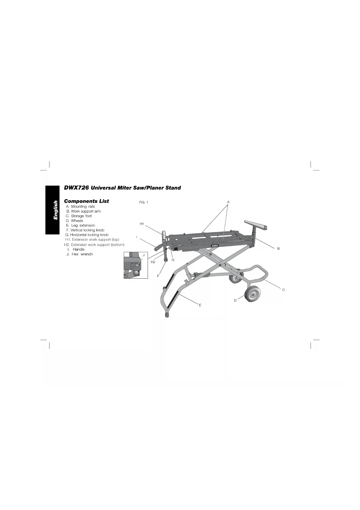
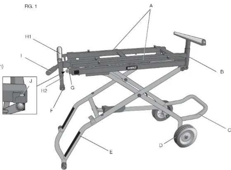
A. Mounting rails
B. Work support arm
C. Storage foot
D.Wheels
E. Leg extension
F. Vertical locking knob
G. Horizontal locking knob
H1. Extension work support (top)
H2. Extension work support (bottom)
I. Handle
J. Hex wrench
Definitions: Safety Guidelines
The definitions below describe the level of severity for each signal word. Please read the manual and pay attention to these symbols.
ADANGER: Indicates an imminently hazardous situation which, if not avoided, will result in death or serious injury.
WARNING: Indicates a potentially hazardous situation which, if not avoided, could result in death or serious injury.
ACAUTION: Indicates a potentially hazardous situation which, if not avoided, may result in minor or moderate injury.
NOTICE: indicates a practice not related to personal injury which, if not avoided, may result in property damage.
IF YOU HAVE ANY QUESTIONS OR COMMENTS ABOUT THIS OR ANY DEWALT TOOL, CALL US TOLL FREE AT: 1-800-4-DEWALT (1-800-433-9258).
This Rolling Miter Saw/Planer Stand is a stand designed to accommodate most miter saws and planers and to provide portability for those units, both in the field and in the shop. If you have any problem with alignment or mounting, call 1-800-4-DEWALT (1-800-433-9258).
SAFETY RULES
WARNING: For your own safety, read the tool instruction manual before using any accessory. Failure to heed these warnings may result in personal injury and serious damage to the tool and the accessory. When servicing this tool, use only identical replacement parts.
WARNING: Failure to follow these rules may result in serious personal injury.
WARNING: To reduce the risk of injury, keep both hands on handle when raising and lowering the stand. The stand has gas assist lifting and may raise unexpectedly when lever is released.
- This product was designed to be used as a stand for miter saws and planers. The stand will support up to 300 lbs (136 kg). Any misuse or abuse can result in product damage or personal injury.
- Do not stand on the work table. It is unsafe to climb, sit or stand on the stand. Do not use the support extensions as a ladder or scaffolding.
- Properly secure the miter saw or planer to the stand before operation. Follow the mounting instructions carefully. Fasten the tool to the saw mounting rails securely as instructed.
- Place the stand on a flat and level surface to prevent rocking or tipping.
Take care during the raising and lowering of the product to reduce the hazard of pinching hands and fingers. - Check the legs and other supports to see that they are properly locked in place before operation.
- Do not modify or use the stand for any operation for which it is not intended.
- ALWAYS use eye protection. All users and bystanders must wear eye protection that conforms to ANSI Z87, 1.
- ALWAYS use safety glasses. Everyday eyeglasses are NOT safety glasses. Also use face or dust mask if cutting operation is dusty. ALWAYS WEAR CERTIFIED SAFETY EQUIPMENT:
ANSI Z87.1 eye protection (CAN/CSA Z94.3)
ANSI S12.6 (S3.19) hearing protection, - NIOSH/OSHA/MSHA respiratory protection.
Carton Contents
1 Rolling miter saw/planer stand
1 Leg extension (E)
2 Work support arms (1 with black cap) (B)
Carton 1:
2 Wheels (D)
1 Handle (I)
1 Storage foot (C)
Carton 2:
2 Extension work support assemblies (H)
2 Wheel/storage foot connectors [left (L) and right (R)] (N)
Hardware bag 1
2 Cord wrap brackets (left and right) (X)
2 M8 washers (JJ)
2 M8 nuts (KK)
Hardware bag 2:
2 Axles (P)
2 Bushings U)
4. Washers (Q)
2 Nuts (R)
Hardware bag 3:
6 M8 x 15 mm button head screws (L)
6 Curved washers (M)
1 M6 x 10 mm button head screw (T)
1 M6 lock washer (Y)
M8 x 20 mm button head screw with thread locking patch (S)
1 M8 lock washer (Z)
Tools Required
- Hex wrench (J) (supplied)
Adjustable wrench
1/2 inch open end wrench
3/4 inch open end wrench
Wire cutting pliers
UNPACKING AND CLEANING
Carefully unpack the product and all loose items from the shipping container(s). Remove the rust-preventative oil from unpainted surfaces using a soft cloth moistened with mineral spirits, paint thinner or denatured alcohol.
NOTICE: Do not use highly volatile solvents such as gasoline, naphtha, acetone or lacquer thinner for cleaning your stand.
Components (Fig. 1)
WARNING: Never modify the stand or any part of it. Damage or personal injury could result.
Refer to Figure 1 for Components List.
ASSEMBLY
WARNING: PINCH AND IMPACT HAZARD. The spring loaded mechanism is under tension and can open unexpectedly, with high force. To reduce the risk of serious personal injury, do not raise or lower stand until the assembly is complete. Do not cut the large securing cable ties (W, Fig. 2) until instructed to do so later in the manual.
WRENCH STORAGE (FIG. 3)
The supplied hex wrench (J) comes in the wrench storage location in the corner of the stand.
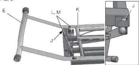
ATTACHING THE LEG EXTENSION (FIG. 2, 3)
IMPORTANT: Place stand upside down on the floor or on a level, stable table as shown in Figure 2.
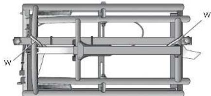
FIG.2
- With stand upside down, insert the leg extension (E) in the stand (K).
- Align the holes and install two M8 x 15 mm button head screws (L) with curved washers (M).
- Tighten securely with the supplied hex wrench (J). FIG. 3
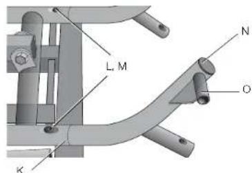
ATTACHING THE WHEEL AND STORAGE FOOT CONNECTOR (FIG. 4)
- With stand still upside down, insert the wheel/storage-foot connector (N) to the stand (K) with wheel extension (O) facing outward.
- Align the hole and install one M8 x 15 mm button head screw (L) with curved washer (M). DO NOT tighten. NOTE: The screw will be tightened completely later in the assembly.
- Attach the other wheel/storage-foot connector in the same manner.
FG4
ATTACHING THE WHEELS (FIG. 5)
- Continuing with stand upside down. Slide axle (P) through washer (Q), wheel bushing (U), wheel (D), other washer (Q) and wheel extension (O) as shown. Ensure the longer side of wheel hub (MM) is facing inward as shown.
- Secure the axle with nut (R). Tighten the nut.

NOTE: Do not overtighten. Overtightening may cause wheel rotation to be impaired.
- Attach the other wheel in the same manner. FIG. 5
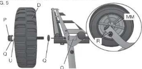
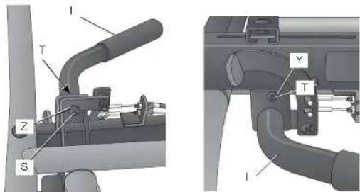
FIG. 6
ATTACHING THE HANDLE (FIG. 6)
- With stand upside down, attach the handle (I) on the end of the stand opposite the wheels with one M8 x 20 mm button head screw (S) and lock washer (Z). Install screw using supplied hex wrench, but DO NOT tighten securely.
- Tum the stand right side up so the wheels and leg extension sit level on the floor or stable table. Ensure the stand remains in the closed position, do not raise the stand.
- Install one M6 x 10 mm button head screw (T) and lock washer (Y) on the other side. Tighten securely with the supplied hex wrench.
- Tighten M8 x 20 mm button head screw (S) added in STEP 1 securely with the supplied hex wrench.
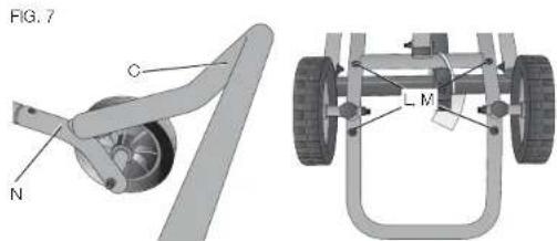
ATTACHING THE STORAGE FOOT (FIG. 7)
- With stand right side up, place the storage foot (C) over the indentations of the wheel and storage-foot connector (N) so when the stand is right side up the storage foot will angle upward.
- Tum stand upside down and align the holes in storage foot and storage foot connector. Install two M8 x 15 mm button head screws (L) with curved washers (M) to attach storage foot and the connector.
- Tighten screws securely with the supplied hex wrench.
- Securely tighten the storage-foot connector screws that were loosely installed in Attaching the Wheel and Storage Foot Connector.
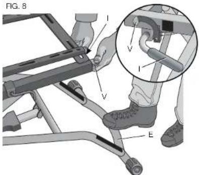
TO RAISE AND LOWER THE STAND (FIG. 2, 8)
The stand has three positions: closed, fully extended and intermediate.
- Turn the stand right side up on the floor.
IMPORTANT: Stand MUST be right side up when cutting white cable ties (W). - Use wire cutting pliers to cut the white cable ties (W) shown in figure 2.
IMPORTANT: DO NOT cut the black cable ties securing the cables that open the stand.
- Place your right foot on the bottom of the extension leg (E).
- Grasp the handle (I) with both hands.
- Use the thumb of your left hand to push down on the red activating lever (V). This disengages the latching mechanism.
- To reach the intermediate position: Lift up on the handle and slowly raise the stand. The stand will stop at the intermediate position. Release the lever.
NOTE: When in the intermediate position, the stand will lower slightly when a tool is placed on it. The intermediate position does not lock against upward motion. The stand relies on the weight of the tool to remain in the intermediate position.
- To fully extended stand: Start in the intermediate position Repeat STEPS 3-5. Lift up on the handle and raise the stand to the fully extended position. The stand will latch in the fully extended position. Release the lever.
- To close stand: Repeat STEPS 3-5. Lift up on the handle and push down until the stand is closed. Release the lever.
English
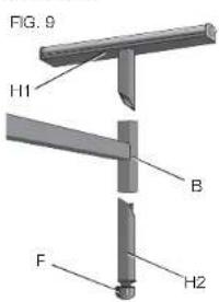
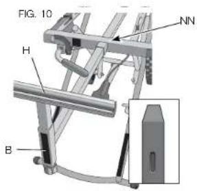
ATTACHING THE EXTENSION WORK SUPPORTS (FIG. 9, 10)
IMPORTANT: Be sure the longer side of the "T" in the work support arm (B) is oriented down as shown in Figure 9. Ensure the arrow on the label points down.
-
Insert the work support arm with the small black cap (B, Fig. 10 inset) into the hole (NN) of the stand closest to the red activating lever. Push the arm in to lock in place.
-
Repeat for other work support arm on opposite end. Push the arm in to lock in place.
- With the stand raised to desired height, place the top piece (H1) of the extension work support into the top of the work support arm (B) hole. Insert the bottom piece (H2) of the extension work support into the bottom hole of the work support arm, with proper orientation to the top piece, refer to figure 9.
- Tighten the vertical lock knob (F).
- Repeat with the other extension work support.
NOTE: The internal locking mechanism keeps the work supports from disengaging.
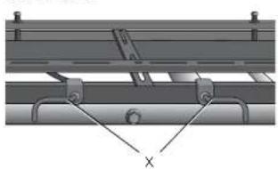
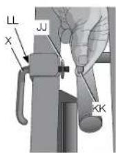
ATTACHING THE CORD WRAPS (FIG. 11, 12)
NOTE: Place the cord wraps (X) in opposite positions to hold the cord securely.
- Place the cord wrap screw (X) into the hole (LL) from outside of stand. Place the washer (JJ) and nut (KK) on cord wrap screw and finger tighten nut.
-
Using a crescent wrench or 1/2 inch open end wrench, tighten the screw securely.
-
Repeat for the other cord wrap. FIG. 11 FIG. 12
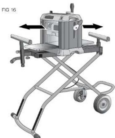
ATTACHING THE TOOL (FIG. 13-16)
WARNING: STABILITY HAZARD. Refer to your tool manufacturer's instructions regarding the securing of your miter saw or planer to a stand or supporting surface. Secure the tool according to both the instructions in this manual and those in your tool manufacturer's manual before operating. Failure to heed these warnings may result in serious personal injury and serious damage to the tool.
WARNING: To reduce the risk of injury, turn miter saw or planer off, disconnect the tool from the power source before assembling the miter saw or planer to the stand. An accidental start-up can cause injury.
- Close stand before attaching the tool.
- Loosen the 6 rail screws (AA) with the supplied hex wrench. Remove the mounting bolts/flat washers (BB) from the mounting rails.
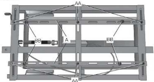
FIG. 13
- Slide the mounting rails (A) to fit the width of the tool. Ensure the mounting slots align with the holes in the tool's feet.
WARNING: Planers MUST be mounted in the orientation shown in Figure 16. -
Place miter saw or planer on the mounting rails (A). Center the tool, both forward and backward and side to side, on the stand.
-
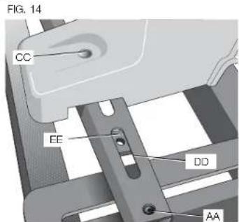
Ensure the mounting holes (CC) in the tool's feet align with the rail slots (DD) and the captured nuts (EE) located in the mounting rails.
- Once the two rails are in place, tighten the rail screws (AA) loosened in STEP 2.
- Insert the mounting bolts/flat washers (BB) (removed in STEP 2) through each of the tool's feet into the captured nut (EE). Tighten securely.
IMPORTANT: The miter saw or planer MUST be positioned so the tool is bolted squarely to the mounting rails. If this is not possible, please call 1-800-4-DEWALT (1-800-433-9258) for technical assistance.
English
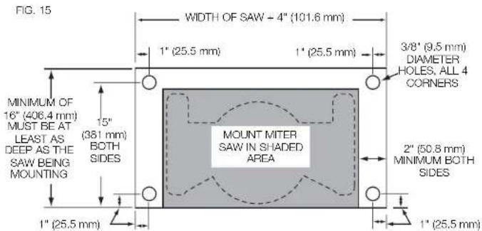
WARNING: STABILITY HAZARD. If the tool's mounting holes do not line up with the slots in the mounting rails, mount the miter saw or planer to a piece of 3/4 inch (19 mm) plywood (See Figure 15 for dimensions). The plywood must be a minimum of 4 inch (101.6 mm) wider than the tool base being mounted and a minimum depth of 16 inch (406.4 mm). Plywood must be at least as deep as the tool base being mounted. Drill 3/8 inch (9.5 mm) holes near both ends of the plywood to align with the slots in the mounting rails as described in Attaching the Tool. Other hardware (not supplied) may be necessary under these circumstances.
WARNING: STABILITY HAZARD. All purchased hardware must be a minimum of Grade 2. Hardware should be 1-1/4 inch (31.8 mm) longer than the thickness of the tool base you are assembling.
NOTICE: To prevent binding and/or inaccuracy, ensure the plywood is not warped or uneven. If binding and/or inaccuracy occurs, replace the plywood with a non-warped, even piece of plywood.
PRODUCT STABILITY TEST (FIG. 16-17)
The rolling miter saw/planer stand is designed to be used in conjunction with a wide variety of miter saws, compound miter saws, sliding compound miter saws and planers.
WARNING: Any tool used with this stand must be properly positioned and secured to ensure stability and to prevent inadvertent tipping.
WARNING: Planers MUST be mounted in the orientation shown in Figure 16.
WARNING: To reduce the risk of serious personal injury, turn tool off and disconnect tool from power source before installing and removing accessories, before adjusting or changing setups or when making repairs. An accidental start-up can cause injury.
WARNING: For your own safety, use two or more people to perform the stability test or serious injury could result.
WARNING: The cutting head MUST be raised on all miter saws, compound miter saws and sliding compound miter saws. All sliding compound miter saws MUST be locked in the rear position. Failure to do so may result in serious personal injury.
WARNING: STABILITY HAZARD. Stay alert. The stand may tip during this procedure. Serious injury may result.
-
Ensure the tool is securely mounted to the stand and is turned off and disconnected from power source.
-
Place a 2-1/2 inch (63.5 mm) thick block of wood (FF) under the front leg (GG) of the stand so that the front leg is raised 2-1/2 inches (63.5 mm) off the floor.
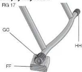
- With one person in front of the stand, and the other person behind, lift the front of the stand slightly, remove the block of wood, and allow the stand to drop to the floor.
- Perform this same test with the block of wood under the rear leg (I-II).
- If the stand tends to tip to the front, reposition the tool toward the rear of the stand. If the stand tends to tip to the rear, reposition the tool forward. Make your adjustment, then repeat the test.
English
OPERATION
WARNING: To reduce the risk of injury. After completing assembly and before each use, ensure all bolts and nuts are properly tightened and all mechanisms operate properly.
WARNING: To reduce the risk of injury, keep both hands on handle and the right foot on the extension leg when raising and lowering the stand. The stand has gas assist lifting and may raise unexpectedly when lever is released.
Refer to To Raise and Lower the Stand under Assembly to adjust the stand to the desired height.
TO EXTEND THE EXTENSION WORK SUPPORTS (FIG. 18)
- Tum the horizontal lock knob (G) counterclockwise.
- Slide the extension work support (H) out or in, depending on the length of the workpiece.
- Tighten the horizontal lock knob.
- Repeat with the other side.
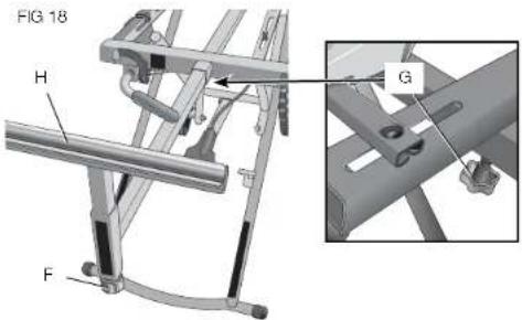
TO ADJUST EXTENSION WORK SUPPORT HEIGHT (FIG. 18)
- Tum the vertical lock knob (F).
- Adjust the extension work support to the desired height.
- Tighten the vertical lock knob.
- Repeat with the other extension work support.
STORAGE AND TRANSPORTATION
WARNING: TIPPING HAZARD. The stand may tip when storing or transporting the stand close to or in the vertical position. Transport or store the stand in the horizontal position to reduce the risk of the stand tipping.
To lower the stand into the storage position, push down on the red activating lever, lift up on the handle, then exert downward pressure on the handle.
Refer to Figure 19 for proper transporting position.
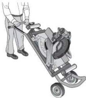
FIG 19
Accessories
WARNING: Since accessories, other than those offered by DEWALT, have not been tested with this product, use of such accessories with this tool could be hazardous. To reduce the risk of injury, only DEWALT, recommended accessories should be used with this product.
Recommended accessories for use with your tool are available at extra cost from your local dealer or authorized service center. If you need assistance in locating any accessory, please contact DEWALT Industrial Tool Co., 701 East Joppa Road, Baltimore, MD 21286, call 1-800-4-DEWALT (1-800-433-9258) or visit our website www.dewalt.com.
Repairs
To assure product SAFETY and RELIABILITY, repairs, maintenance and adjustments should be performed by a DEWALT factory service center, a DEWALT authorized service center or other qualified service personnel. Always use identical replacement parts.
Register Online
Thank you for your purchase. Register your product now for:
WARRANTY SERVICE: Registering your product will help you obtain more efficient warranty service in case there is a problem with your product.
CONFIRMATION OF OWNERSHIP: In case of an insurance loss, such as fire, flood or theft, your registration of ownership will serve as your proof of purchase.
FOR YOUR SAFETY: Registering your product will allow us to contact you in the unlikely event a safety notification is required under the Federal Consumer Safety Act.
Register online at www.dewalt.com/register.
Three Year Limited Warranty
DEWALT will repair, without charge, any defects due to faulty materials or workmanship for three years from the date of purchase. This warranty does not cover part failure due to normal wear or tool abuse. For further detail of warranty coverage and warranty repair information, visit www.dewalt.com or call 1-800-4-DEWALT (1-800-433-9258). This warranty does not apply to accessories or damage caused where repairs have been made or attempted by others. This warranty gives you specific legal rights and you may have other rights which vary in certain states or provinces.
In addition to the warranty, DFWALT tools are covered by our:
1 YEAR FREE SERVICE
DEWALT will maintain the tool and replace worn parts caused by normal use, for free, any time during the first year after purchase.
90 DAY MONEY BACK GUARANTEE
If you are not completely satisfied with the performance of your DEWALT Power Tool, Laser, or Nailer for any reason, you can return it within 90 days from the date of purchase with a receipt for a full refund - no questions asked.
LATIN AMERICA: This warranty does not apply to products sold in Latin America. For products sold in Latin America, see country specific warranty information contained in the packaging, call the local company or see website for warranty information.
FREE WARNING LABEL REPLACEMENT: If your warning labels become illegible or are missing, call 1-800-4-DzWALT (1-800-433-9258) for a free replacement.
English
A
2 Aces (P)
2 Bagues (U)
4 Rondelles (Q)
2 Ecrous
Sac de quincaillerie 3:
KINGDOMS OF THE HONORS AND HONORS OF THE GENDER, THE HONORS OF THE FATHER, THE HONORS OF THE MOTHER, THE HONORS OF THE FATHER AND MOTHER, THE HONORS OF THE FATHER AND MOTHER AND THE HONORS OF THE FATHER AND MOTHER AND THE HONORS OF THE FATHER AND MOTHER AND THE HONORS OF THE FATHER AND MOTHER AND THE HONORS OF THE FATHER AND MOTHER AND THE HONORS OF THE FATHER AND MOTHER AND THE HONORS OF THE FATHER AND MOTHER AND THE HONORS OF THE FATHER AND MOTHER AND THE HONORS OF THE FATHER AND MOTHER AND THE HONOR
AVERAGEMENT
LIFE LIVING (1) AND THE HUMAN (2)
LIFE LIVING (1) AND THE HUMAN (2)
LIFE LIVING (1) AND THE HUMAN (2)
LIFE LIVING (1) AND THE HUMAN (2)
AOVERTENCIA
MENITOKI, ARIANA MARRA, MD (1976), MARRA, MD (1982), MARRA, MD (1985), MARRA, MD (1987), MARRA, MD (1989), MARRA, MD (1990), MARRA, MD (1993), MARRA, MD (1994), MARRA, MD (1995), MARRA, MD (1996), MARRA, MD (1997), MARRA, MD (1998), MARRA, MD (1999), MARRA, MD (2000), MARRA, MD (2001)
CAUTION
ATTACHING THE HANDLE (FIG. 6)
Local D, Col. Obrera (55) 5588 9377
MERIDA.YUC
Calle 63 #459-A - Col. Centro (999) 928 5038
MONTERREY, N.L.
Av. Francisco I. Madero 831 Poniente - Col. Centro (818) 375 23 13
PUEBLA, PUE
17 Norte #205 - Col. Centro (222) 246 3714
QUERETARO, QRO
Av. San Roque 274 - Col. San Gregorio (442) 2 17 63 14
SAN LUIS POTOSI, SLP
10.2.3.19 2008, 12th edn. W.K. Winkler, V.W. Kudryavtsev, and M. L. G. S. Shukla (eds), The theory of the quantum field, 2nd edn., and A.M. R. E. P. Y. L. Zel'dovich (eds), 2nd edn., vol. 1, 1995.
AVERTISSEMENT
LASSER LEUIS RENOMA 1548 LA FONDAIRE AU MEMBRIUM DE L'INTERNE, CHRONIQUE DE FINANCE DES PÉRISES DE L'INDUSTRAT. CHRONIQUE DE FINANCE DES PÉRISES DE L'INDUSTRAT. CHRONIQUE DE FINANCE DES PÉRISES DE L'INDUSTRAT. CHRONIQUE DE FINANCE DES PÉRISES DE L'INDUSTRAT. CHRONIQUE DE FINANCE DES PÉRISES DE L'INDUSTRAT. CHRONIQUE DE FINANCE DES PÉRISES DE L'INDUSTRAT. CHRONIQUE DE financement des pêriots de la société à l'Industrie. CHRONIQUE DE FINANCE DES PÉRISES DE L'INDUSTRAT. CHRONIQUE DE FINANCE DES PÉRISES DE L'INDUSTRAT. CHRONIQUE DE FINANCE DES PÉRISES DE L'INDUSTRAT. CHRONIQUE DE FINANCE DES PÉRISES DE L'INDUSTRAT. CHRONIQUE DE FINANCE DES PÉRISES DE L'INDUSTRAT. CHRONIQUE D'INDUSTRAT. CHRONIQUE DE FINANCE DES PÉRISES DE L'INDUSTRAT. CHRONIQUE DE FINANCE DES PÉRISES DE L'INDUSTRAT. CHRONIQUE DE FINANCE DES PÉRISES DE L'INDUSTRAT. CHRONIQUE DE FINANCE DES PÉRISES DE L'INDUSTRAT. CHRONIQUE DE FINANCE DES PÉRISES DE L'INDUSTRATE. CHRONIQUE DE FINANCE DES PÉRISES DE L'INDUSTRAT. CHRONIQUE DE FINANCE DES PÉRISES DE L'INDUSTRAT. CHRONIQUE DE FINANCE DES PÉRISES DE L'INDUSTRAT. CHRONIQUE DE FINANCE DES PÉRISES DE L'INDUSTRAT. CHRONIQUE DE FINANCE DES PÉRISES DE L'INDUSTRAT. CHRONIQUE DELPPERATION DES PÉRISES DE L'INDUSTRAT. CHRONIQUE DELPPERATION DES PÉRISES DE L'INDUSTRAT. CHRONIQUE DELPPERATION DES PÉRISES DE L'INDUSTRAT. CHRONIQUE DELPPERATION DES PÉRISES DE L'INDUSTRAT. CHRONIQUE DELPPERATION DES PÉRISES DE L'INDUSTRAT. CHRONIC DELPPERATION DES PÉRISES DE L'INDUSTRAT. CHRONIC DELPPERATION DES PÉRISES DE L'INDUSTRAT. CHRONIC DELPPERATION DES PÉRISES DE L'INDUSTRAT. CHRONIC DELPPERATION DES PÉRISES DE L'INDUSTRAT. CHRONIC DELPPERATION DES PÉRISES DE L'INDUstrAT. CHRONIC DELPPERATION DES PÉRISES DE L'INDUSTRAT. CHRONIC DELPPERATION DES PÉRISES DE L'INDUSTRAT. CHRONIC DELPPERATION DES PÉRISES DE L'INDUSTRAT. CHRONIC DELPPERATION DES PÉRISES DE L'INDUSTRAT. CHRONIC DELPPERATION DES PÉRISES OF THE INDUSTRAT. CHRONIC DELPPERATION DES PÉRISES OF THE INDUSTRAT. CHRONIC DELPPERATION DES PÉRISES OF THE INDUSTRAT. CHRONIC DELPPERATION DES PÉRISES OF THE INDUSTRAT. CHRONIC DELPPERATION DES PÉRISES OF THE INDUSTRAT. CHRONIC DELPPERATION DES PÉRISES OF THE INDUSTRAT. CHRONIC DELPPERATION DES PÉRISES OF THE INDUSTRAT. CHRONIC DELPPERATION DES PÉRISES OF THE INDUSTRAT. CHRONIC DELPPERATION DES PÉRISES OF THE INDUSTRAT. CHRONIC DELPPERATION DES PÉRISES OF THE INDUSTRAT. CHRONIC DELPPERATION DES PÉRISES OF THE IND USTRAT. CHRONIC DELPPERATION DES PÉRISES OF THE IND USTRAT. CHRONIC DELPPERATION DES PÉRISES OF THE IND USTRAT. CHRONIC DELPPERATION DES PÉRISES OF THE IND USTRAT. CHRONIC DELPPERATION DES PÉRISES OF THE IND USTRAT. CHRONIC DELPPERATION DES PÉRISES OF THE INDUSTRAT. CHRONIC DELPPERATION DES PÉRISES OF THE IND USTRAT. CHRONIC DELPPERATION DES PÉRISES OF THE IND USTRAT. CHRONIC DELPPERATION DES PÉRISES OF THE IND USTRAT. CHRONIC DELPPERATION DES PÉRISES OF THE INDUSTRAT. CHRONIC DELPPERATION DES PÉRISES OF THE INDUSTRAT. CHRONIC DELPPERATION DES PÉRISES OF THE IND USTRAT. CHRONIC DELPPERATION DES PÉRISES OF THE IND USTRAT. CHRONIC DELPPERATION DES PÉRISES OF THE INDUSTRAT. CHRONIC DELPPERATION DES PÉRISES OF THE IND USTRAT. CHRONIC DELPPERATION DES PÉRISES OF THE INDUSTRAT. CHRONIC DELPPERATION DES PÉRISES OF THE IND USTRAT. CHRONIC DELPPERATION DES PÉRISES OF THE IND USTRAT. CHRONIC DELPPERATION DES PÉRISES OF THE INDUSTRAT. CHRONIC DELPPERATION DES PÉRISES OF THE INDUSTRAT. CHRONIC DELPPERATION DES PÉRISES OF THE INDUSTRAT. CHRONIC DELPPERATION DES PÉRISES OF THE IND USTRAT. CHRONIC DELPPERATION DES PÉRISES OF THE INDUSTRAT. CHRONIC DELPPERATION DES PÉRISES OF THE IND USTRAT. CHRONIC DELPPERATION DES PÉRISES OF THE INDUSTRAT. CHRONIC DELPPERATION DES PÉRISES OF THE INDUSTRAT. CHRONIC DELPPERATION DES PÉRISES OF THE IND USTRAT. CHRONIC DELPPERATION DES PÉRISES OF THE INDUSTRAT. CHRONIC DELPPERATION DES PÉRISES OF THE INDUSTRAT. CHRONIC DELPPERATION DES PÉRISES OF THE INDUSTRAT. CHRONIC DELPPERATION DES PÉRISES OF THE INDUSTRAT. CHRONIC DELPPERATION DES PÉRISES OF THE IND/USTRAT. CHRONIC DELPPERATION DES PÉPRISESDI GENE TRES AUF MEDIATERI.
ADVERTENCA
MENINGOOLING 1000000000000000000000000000000000000000000000000000000000000000000000000000000000000000000000000000
WARNING
APPLY HEAT OR FREE. HEAT MAY CAUSE CONTAINER TO BURST
AVERTISSENT CONTENU SOUS PEAEDON ME PA2 PERCEK
DE CHAUFUR DE JU. LA CHAFUR PEUT FAIRE ECLATER LE CONTENANT.
ADVERTENCA CONTINUING SAID PRESENNO PERSURGER
AADVERTECAI INDINEARN,NI2OBDPRRNE,NOACENRAEAS 2408.01-01-0690,NI(IN)ABCDHJF5G,TAEETLAA

SOLAMENTE PARA PROPOSITO DE MEXICO:
IMPORTDAGO PROC: DEWALT INDUSTRIAL TOOL CO. S.A. DE C.V. AVENIDA ANTONIO DOVALI JAIME, # 70 TOPRE B PISO 9
COLONIA LA FE, SANTA FE
CODIGO POSTAL:01210
DELEGACION ALVAROOBREGON
MEXICO D.F.
TEL: (52) 555-326-7100
B.R.C. BDC810626-1W
DEWALT Industrial Tool Co., 701 East Joppa Road, Baltimore, MD 21286
(OCT13) Part No. N361420 DWX726 Copyright © 2011, 2013 DEWALT
The following are trademarks for one or more DEWALT power tools: the yellow and black color scheme; the "D" shaped air intake grill; the array of pyramids on the handgrip; the kit box configuration; and the array of lozenge-shaped humps on the surface of the tool.