DW714 - Saw DEWALT - Free user manual and instructions
Find the device manual for free DW714 DEWALT in PDF.
Download the instructions for your Saw in PDF format for free! Find your manual DW714 - DEWALT and take your electronic device back in hand. On this page are published all the documents necessary for the use of your device. DW714 by DEWALT.
USER MANUAL DW714 DEWALT
DW714 Final Page size: A4 (210 mm x 297 mm)2 Copyright D
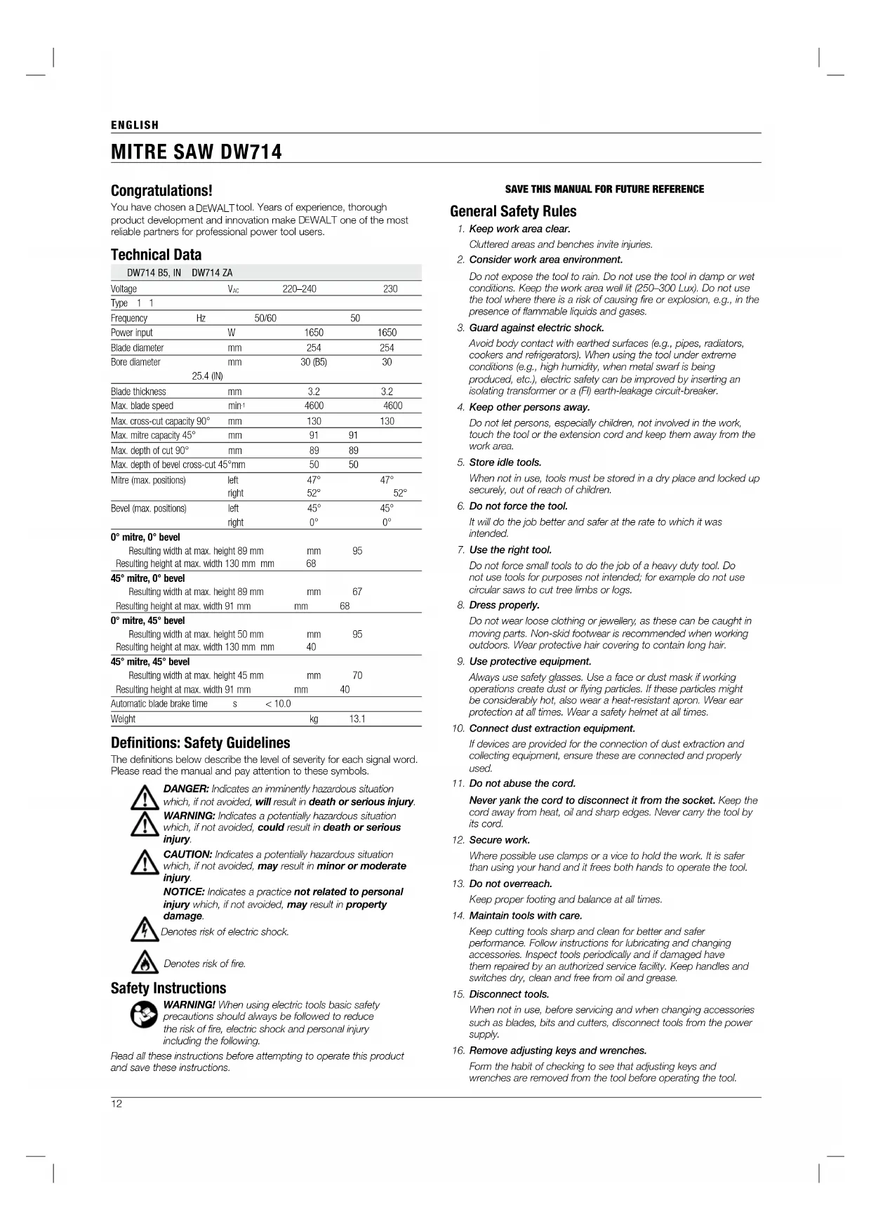
Congratulations! You have chosen a DeWALT tool. Years of experience, thorough product development and innovation make D
WALT one of the most reliable partners for professional power tool users. Technical Data DW714 B5, IN DW714 ZA Voltage V
DANGER: Indicates an imminently hazardous situation
which, if not avoided, will result in death or serious injury.
WARNING: Indicates a potentially hazardous situation
which, if not avoided, could result in death or serious injury. CAUTION: Indicates a potentially hazardous situation which, if not avoided, may result in minor or moderate injury. NOTICE: Indicates a practice not related to personal injury which, if not avoided, may result in property damage. Denotes risk of electric shock. Denotes risk of fire. Safety Instructions WARNING! When using electric tools basic safety precautions should always be followed to reduce the risk of fire, electric shock and personal injury including the following. Read all these instructions before attempting to operate this product and save these instructions.
SAVE THIS MANUAL FOR FUTURE REFERENCE
General Safety Rules
1. Keep work area clear.
Cluttered areas and benches invite injuries.
2. Consider work area environment.
Do not expose the tool to rain. Do not use the tool in damp or wet conditions. Keep the work area well lit (250–300 Lux). Do not use the tool where there is a risk of causing fire or explosion, e.g., in the presence of flammable liquids and gases.
3. Guard against electric shock.
Avoid body contact with earthed surfaces (e.g., pipes, radiators, cookers and refrigerators). When using the tool under extreme conditions (e.g., high humidity, when metal swarf is being produced, etc.), electric safety can be improved by inserting an isolating transformer or a (FI) earth-leakage circuit-breaker.
4. Keep other persons away.
Do not let persons, especially children, not involved in the work, touch the tool or the extension cord and keep them away from the work area.
5. Store idle tools.
When not in use, tools must be stored in a dry place and locked up securely, out of reach of children.
6. Do not force the tool.
It will do the job better and safer at the rate to which it was intended.
7. Use the right tool.
Do not force small tools to do the job of a heavy duty tool. Do not use tools for purposes not intended; for example do not use circular saws to cut tree limbs or logs.
Do not wear loose clothing or jewellery, as these can be caught in moving parts. Non-skid footwear is recommended when working outdoors. Wear protective hair covering to contain long hair.
9. Use protective equipment.
Always use safety glasses. Use a face or dust mask if working operations create dust or flying particles. If these particles might be considerably hot, also wear a heat-resistant apron. Wear ear protection at all times. Wear a safety helmet at all times.
10. Connect dust extraction equipment.
If devices are provided for the connection of dust extraction and collecting equipment, ensure these are connected and properly used.
11. Do not abuse the cord.
Never yank the cord to disconnect it from the socket. Keep the cord away from heat, oil and sharp edges. Never carry the tool by its cord.
Where possible use clamps or a vice to hold the work. It is safer than using your hand and it frees both hands to operate the tool.
13. Do not overreach.
Keep proper footing and balance at all times.
14. Maintain tools with care.
Keep cutting tools sharp and clean for better and safer performance. Follow instructions for lubricating and changing accessories. Inspect tools periodically and if damaged have them repaired by an authorized service facility. Keep handles and switches dry, clean and free from oil and grease.
15. Disconnect tools.
When not in use, before servicing and when changing accessories such as blades, bits and cutters, disconnect tools from the power supply.
16. Remove adjusting keys and wrenches.
Form the habit of checking to see that adjusting keys and wrenches are removed from the tool before operating the tool.ENGLISH
17. Avoid unintentional starting.
Do not carry the tool with a finger on the switch. Be sure that the tool is in the “off” position before plugging in.
18. Use outdoor extension leads.
Before use, inspect the extension cable and replace if damaged. When the tool is used outdoors, use only extension cords intended for outdoor use and marked accordingly.
Watch what you are doing. Use common sense. Do not operate the tool when you are tired or under the influence of drugs or alcohol.
20. Check for damaged parts.
Before use, carefully check the tool and mains cable to determine that it will operate properly and perform its intended function. Check for alignment of moving parts, binding of moving parts, breakage of parts, mounting and any other conditions that may affect its operation. A guard or other part that is damaged should be properly repaired or replaced by an authorized service centre unless otherwise indicated in this instruction manual. Have defective switches replaced by an authorized service centre. Do not use the tool if the switch does not turn it on and off. Never attempt any repairs yourself. WARNING! The use of any accessory or attachment or performance of any operation with this tool other than those recommended in this instruction manual may present a risk of personal injury.
21. Have your tool repaired by a qualified person.
This electric tool complies relevant safety rules. Repairs should only be carried out by qualified persons using original spare parts; otherwise this may result in considerable danger to the user. Additional Safety Rules for Mitre Saws
- The machine is provided with a special configured power supply cord which can only be replaced by the manufacturer or its authorised service agent.
- Do not use the saw to cut other materials than those recommended by the manufacturer.
- Do not operate the machine without guards in position, or if guards do not function or are not maintained properly.
- Ensure that the arm is securely fixed when performing bevel cuts.
- Keep the floor area around the machine level, well-maintained and free of loose materials, e.g., chips and cut-offs.
- Use correctly sharpened saw blades. Observe the maximum speed mark on the saw blade.
- Make sure all locking knobs and clamp handles are tight before starting any operation.
- Never place either hand in the blade area when the saw is connected to the electrical power source.
- Never attempt to stop a machine in motion rapidly by jamming a tool or other means against the blade; serious accidents can occur.
- Before using any accessory consult the instruction manual. The improper use of an accessory can cause damage.
- Use a holder or wear gloves when handling a saw blade.
- Ensure that the saw blade is mounted correctly before use.
- Make sure that the blade rotates in the correct direction.
- Take care when slotting.
- Do not use blades of larger or smaller diameter than recommended. For the proper blade rating refer to the technical data. Use only the blades specified in this manual, complying with EN 847-1.
- Consider applying specially designed noise-reduction blades.
- Do not use HSS blades.
- Do not use cracked or damaged saw blades.
- Do not use any abrasive or diamond discs.
- Never use your saw without the kerf plate.
- Raise the blade from the kerf in the workpiece prior to releasing theswitch.
- Do not wedge anything against the fan to hold the motor shaft.
- The blade guard on your saw will automatically raise when the arm is brought down; it will lower over the blade when head lock up release lever (cc) is pushed.
- Never raise the blade guard manually unless the saw is switched off. The guard can be raised by hand when installing or removing saw blades or for inspection of the saw.
- Check periodically that the motor air slots are clean and free ofchips.
- Replace the kerf plate when worn. Refer to service parts listincluded.
- Disconnect the machine from the mains before carrying out any maintenance work or when changing the blade.
- Never perform any cleaning or maintenance work when the machine is still running and the head is not in the rest position.
- When possible, always mount the machine to a bench.
- The front section of the guard is louvered for visibility while cutting. Although the louvers dramatically reduce flying debris, they are openings in the guard and safety glasses should be worn at all times when viewing through the louvers.
- Connect the saw to a dust collection device when sawing wood. Always consider factors which influence exposure of dust such as: -– type of material to be machined (chip board produces more dust than wood); -– sharpness of the saw blade; -– correct adjustment of the saw blade, -– dust extractor with air velocity not less than 20 m/s. Ensure that the local extraction as well as hoods, baffles and chutes are properly adjusted.
- Please be aware of the following factors influencing exposure to noise: -– use saw blades designed to reduce the emitted noise; -– use only well sharpened saw blades;
- Machine maintenance shall be conducted periodically;
- Machine faults, including guards or saw blade, shall be reported as soon as they are discovered;
- Provide adequate general or localized lighting;
- Ensure the operator is adequately trained in the use, adjustment and operation of the machine;
- Ensure that any spacers and spindle rings are suitable for the purpose as stated in this manual.
- Refrain from removing any cut-offs or other parts of the workpiece from the cutting area while the machine is running and the saw head is not in the rest position
- Never cut workpieces shorter than 30 mm (Figure 34).
- Without additional support the machine is designed to accept the maximum workpiece size of: – Height 89 mm by width 89 mm by length 500 mm – Longer workpieces need to be supported by suitable additional table(work support). Always clamp the workpiece safely.
- In case of an accident or machine failure, immediately turn the machine off and disconnect machine from the power source.
- Report the failure and mark the machine in suitable form to prevent other people from using the defective machine.
- When the saw blade is blocked due to abnormal feed force during cutting, turn the machine off and disconnect it from power supply. Remove the workpiece and ensure that the saw blade runs free. Turn the machine on and start new cutting operation with reduced feed force.
- Never cut light alloy, especially magnesium.
- Whenever the situation allows, mount the machine to a bench using bolts with a diameter of 8 mm and 40 mm in length. Residual Risks The following risks are inherent to the use of saws: – injuries caused by touching the rotating partsENGLISH
In spite of the application of the relevant safety regulations and the implementation of safety devices, certain residual risks cannot be avoided. These are: – Impairment of hearing. – Risk of accidents caused by the uncovered parts of the rotating saw blade. – Risk of injury when changing the blade. – Risk of squeezing fingers when opening the guards. – Health hazards caused by breathing dust developed when sawing wood, especially oak, beech and MDF. The following factors increase the risk of breathing problems: – No dust extractor connected when sawing wood. – Insufficient dust extraction caused by uncleaned exhaust filters. Markings on Tool The following pictograms are shown on the tool: Read instruction manual before use. Wear ear protection. Wear eye protection. Keep hands away from blade. DATE CODE POSITION (FIG. 1) The Date Code (u), which also includes the year of manufacture, is printed into the housing. Example: 2016 XX XX Year of Manufacture Package Contents The package contains: 1 Mitre Saw 1 Blade wrench stored in wrench pocket 1 Saw blade 1 Dust bag 1 Vertical clamp 2 Work support 1 Instruction manual
- Check for damage to the tool, parts or accessories which may have occurred during transport.
- Take the time to thoroughly read and understand this manual prior to operation. Description (Fig. 1–5, 14)
WARNING: Never modify the power tool or any part of it.
WALT DW714 Mitre Saw has been designed for professional cutting wood and aluminum, wood products, aluminum products and plastics. It performs the sawing operations of cross-cutting, bevelling and mitring easily, accurately and safely. This unit is designed for use with a nominal blade diameter 254 mm carbide tip blade. DO NOT use under wet conditions or in presence of flammable liquids or gases. These miter saws are professional power tools. DO NOT let children come into contact with the tool. Supervision is required when inexperienced operators use this tool.
- This product is not intended for use by persons (including children) suffering from diminished physical, sensory or mental abilities; lack of experience, knowledge or skills unless they are supervised by a person responsible for their safety. Children should never be left alone with this product. WARNING! Do not use the machine for purposes other than intended. Electrical Safety The electric motor has been designed for one voltage only. Always check that the power supply corresponds to the voltage on the rating plate. Your D
WALT tool is double insulated in accordance with IEC61029; therefore no earth wire is required.
WARNING: 127V units have to be operated via a fail-safe
isolating transformer with an earth screen between the primary and secondary winding. If the supply cord is damaged, it must be replaced by a specially prepared cord available through the DeWALT service organisation. Mains Plug Replacement (Middle East and Africa) If a new mains plug needs to be fitted:
- Safely dispose of the old plug.
- Connect the brown lead to the live terminal in the plug.
- Connect the blue lead to the neutral terminal.
WARNING: No connection is to be made to the earth
Follow the fitting instructions supplied with good quality plugs. Recommended fuse: 13 A. Using an Extension Cable If an extension cable is required, use an approved 3–core extension cable suitable for the power input of this tool (see technical data). The minimum conductor size is 1.5 mm
When using a cable reel, always unwind the cable completely. ASSEMBLY
WARNING: To reduce the risk of injury, turn unit off
and disconnect machine from power source before installing and removing accessories, before adjusting or changing set-ups or when making repairs. Be sure the trigger switch is in the OFF position. An accidental start- up can cause injury. Unpacking (Fig. 1, 2, 4, 5)
1. Remove the saw from the packing material carefully using the
carrying handle (m).
2. Use the supplied blade wrench (i) to remove the mitre lock
temporary shipping bolt (hh).
3. Assemble the mitre lock knob (e) to the mitre saw arm.
4. Press down the operating handle (a) and pull out the lock down pin
5. Gently release the downward pressure and allow the arm to rise to
its full height. Bench Mounting (Fig. 6)
1. Holes (j) are provided in all four feet to facilitate bench mounting.
Two different sized holes are provided to accommodate different sizes of bolts. Use either hole; it is not necessary to use both. Bolts with a diameter of 8 mm and 40 mm in length is suggested. Always mount your saw firmly to prevent movement. To enhance the portability, the tool can be mounted to a piece of 15 mm or thinner plywood which can then be clamped to your work support or moved to other job sites and reclamped.
2. When mounting your saw to a piece of plywood, make sure that
the mounting screws do not protrude from the bottom of the wood. The plywood must sit flush on the work support. When clamping the saw to any work surface, clamp only on the clamping bosses where the mounting screw holes are located. Clamping at any other point will interfere with the proper operation of the saw.
3. To prevent binding and inaccuracy, be sure the mounting surface is
not warped or otherwise uneven. If the saw rocks on the surface, place a thin piece of material under one saw foot until the saw is firm on the mounting surface. Mounting the Saw Blade (Fig. 9, 10, 11, 12)
WARNING: To reduce the risk of injury, turn unit off
and disconnect machine from power source before installing and removing accessories, before adjusting or changing set-ups or when making repairs. Be sure the trigger switch is in the OFF position. An accidental start- up can cause injury.
- Never depress the spindle lock button while the blade is under power or coasting.
- Do not cut light alloy and ferrous metal (containing iron or steel) or masonry or fibre cement product with this mitresaw.
- Depress the head lock up release lever (cc) (if equipped) to release the lower guard (b),then raise the lower guard as far as possible.
- Should use the corresponding blade cutting differentmaterials.
1. With the lower guard held in the raised position loosen the guard
bracket screw (kk) until the guard bracket (ll) raises far enough to access the blade locking screw (nn).
2. Depress the spindle lock button (x) with one hand and with the
other hand use the wrench (i) provided to loosen the left-hand threaded blade locking screw (nn) by turning clockwise.
WARNING: To use the spindle lock, press the button as
shown and rotate the spindle by hand until you feel the lockengage. Continue to hold the lock button in to keep the spindle fromturning.
3. Remove the blade locking screw (nn) and the outside arbor
4. Install the saw blade (oo) onto the blade adaptor seated directly
against the inside arbor collar (rr), making sure that the teeth at the bottom edge of the blade are pointing toward the back of the saw (away from the operator).
5. Replace the outer arbor collar (pp).
6. Tighten the blade locking screw (nn) carefully by turning counter-
clockwise while holding the spindle lock engaged with your otherhand.
7. Return the guard bracket (ll) to its original position and firmly
tighten the guard bracket screw (kk) to hold bracket in place. WARNING! Be aware the saw blade shall be replaced in the described way only. Only use saw blades as specified under Technical Data. WARNING! The guard bracket (ll) must be returned to its original position and the guard bracket screw (kk) tightened before activating the saw. WARNING! Failure to do so may allow the guard to contact the spinning saw blade resulting in damage to the saw and severe personal injury. Adjustments
WARNING: To reduce the risk of injury, turn unit off
and disconnect machine from power source before installing and removing accessories, before adjusting or changing set-ups or when making repairs. Be sure the trigger switch is in the OFF position. An accidental start-up can cause injury. Your mitre saw was accurately adjusted at the factory. If readjustment due to shipping and handling or any other reason is required, follow the steps below to adjust your saw. Once made, these adjustments should remain accurate. CHECKING AND ADJUSTING THE MITRE SCALE (FIG. 13, 14, 15)
2. Pull down the head until the blade just enters the saw kerf (s).
3. Place a square (tt) against the left side fence (v) and blade (oo)
WARNING: Do not touch the tips of the blade teeth with
the square. If adjustment is required, proceed as follows:
5. Loosen the left side fence clamping knob (k) and use the wrench (i)
to loosen the fence stop screw (jj). Remove the left side fence (v).
6. Pull down the head and lock it in the lowered position by pushing in
the lock down pin. Replace the left side fence and place a square against the left side fence and the blade. With the left side fence against the square use the wrench (i) to tighten the hex bolts on the fence in the order from the right side. CHECKING AND ADJUSTING THE BLADE TO THE TABLE (FIG. 16–21)
1. Loosen the bevel clamp knob (p).
2. Press the mitre arm to the right to ensure it is fully vertical with
the angle position stop (z) located against the vertical position adjustment stop (bb) and tighten the bevel clamp knob.
3. Pull down the head until the blade just enters the saw kerf (s).
4. Place a set square (tt) on the table and up against the blade (oo)
WARNING: Do not touch the tips of the blade teeth with
If adjustment is required, proceed as follows:
5. Loosen the lock nut (ww) a few turns, and while making sure the
stop screw (bb) is firmly in contact with the angle position stop (z), turn the vertical position adjustment stop screw (bb) in or out until the blade is at 90º to the table as measured with the square.
6. Firmly tighten the lock nut (ww) while holding the stop screw
7. If the bevel pointer (xx) does not indicate zero on the bevel scale
(q), loosen the screw (yy) that secures the pointer and move the pointer as necessary. ADJUSTING THE FENCE (FIG. 22) The upper part of the fence can be adjusted to provide clearance, allowing the saw to bevel to 45° left and 0° right. To adjust the left fence (v):
1. Loosen the left side fence clamping knob (k) and slide the fence to
2. Make a dry run with the saw switched off and check for clearance.
Adjust the fence to be as close to the blade as practical to provide maximum workpiece support, without interfering with the up and down movement of the arm.
3. Tighten the knob securely.
WARNING: The guide grooves (zz) can become clogged
with sawdust. Use a stick or some low pressure air to clear the guide grooves. CHECKING AND ADJUSTING THE BEVEL ANGLE (FIG. 22, 23)
1. Loosen the left side fence clamping knob (k) and slide the upper
part of the left side fence to the left as far as it will go.
2. Loosen the bevel clamp knob (p) and move the saw arm to the
left until the angle position stop (z) rests on the bevel position adjustment stop (aa). This is the 45° bevel position. If adjustment is required, proceed as follows:
3. Loosen the locknut (ww) a few turns and turn the bevel position
adjustment stop screw (aa) in or out until the pointer (xx) indicates 45° with the angle position stop (z) resting on the bevel position adjustment stop.
4. Firmly tighten the lock nut (ww) while holding the stop screw
stop screws must be adjusted to allow the saw arm to move asnecessary. ADJUSTING THE DEPTH STOP (GROOVE CUTS) (FIG. 33) The depth stop adjustment screw (ss) can be turned clockwise to reach the desired depth of cut for grooves. – Tilt the saw head to the desired position for the groovecut. – Turn the adjustment screw (ss) clockwise until the end of the screw touches the housing stop. – Guide the tool head slowly upward. NOTE: AFTER THE GROOVE CUT IS COMPLETE RETURN THE DEPTH STOP ADJUSTMENT SCREW TO THE ORIGINALPOSITION. NOTE: ENSURE THAT THE SAW BLADES DO NOT TOUCH ANY PART OF THE BASE OR KERFPLATE.
GUARD ACTUATION AND VISIBILITY
The blade guard on your saw has been designed to automatically raise when the arm is brought down and to lower over the blade when the arm is raised. The guard can be raised by hand when installing or removing saw blades or for inspection of the saw. NEVER RAISE THE BLADE GUARD MANUALLY UNLESS THE SAW IS TURNED OFF. NOTE: Certain special cuts will require that you manually raise the guard. The front section of the guard is louvered for visibility while cutting. Although the louvers dramatically reduce flying debris, they are openings in the guard and safety glasses should be worn at all times when viewing through the louvers.
AUTOMATIC ELECTRIC BRAKE
Your saw is equipped with an automatic electric blade brake which stops the saw blade within 10 seconds of trigger release. This is notadjustable. On occasion, there may be a delay after trigger release to brake engagement. On rare occasions, the brake may not engage at all and the blade will coast to a stop. If a delay or “skipping” occurs, turn the saw on and off 4 or 5 times. If the condition persists, have the tool serviced by an authorized DeWALT
service center. Always be sure the blade has stopped before removing it from the kerf. The brake is not a substitute for guards or for ensuring your own safety by giving the saw your complete attention. Brushes (Fig. 1)
WARNING: To reduce the risk of serious personal injury,
turn off the tool and disconnect it from the power source before attempting to move it, change accessories or make any adjustments. Inspect carbon brushes regularly by unplugging the tool, removing the motor end cap (w) and removing the brush cap that holds the spring- loaded brush assembly. Keep brushes clean and sliding freely in their guides. Always replace a used brush in the same orientation in the holder as it was prior to its removal. Use only identical DeWALT brushes. Use of the correct grade of brush is essential for proper operation of electric brake. New brushes are essential for proper operation of the electric brake. New brush assemblies are available at DeWALT service centers. The tool should be allowed to “run in” (run at no load) for 10 minutes before use to seat new brushes. The electric brake may be erratic in operation until the brushes are properly seated (worn in). Always replace the brush inspection cap after inspection or servicing the brushes. While “running in” DO NOT TIE, TAPE, OR OTHERWISE LOCK THE TRIGGER SWITCH ON. HOLD BY HAND ONLY. OPERATION Instructions for Use
WARNING: Always observe the safety instructions and
applicable regulations.
WARNING: To reduce the risk of serious personal
injury, turn tool off and disconnect tool from power source before making any adjustments or removing/ installing attachments or accessories. Ensure the machine is placed to satisfy your ergonomic conditions in terms of table height and stability. The machine site shall be chosen so that the operator has a good overview and enough free surrounding space around the machine that allows handling of the workpiece without any restrictions. To reduce effects of vibration make sure the environment temperature is not too cold, machine and accessory is well maintained and the workpiece size is suitable for this machine. Prior to Operation
- Install the appropriate saw blade. Do not use excessively worn blades. The maximum rotation speed of the tool must not exceed that of the saw blade.
- Do not attempt to cut excessively small pieces.
- Allow the blade to cut freely. Do not force.
- Allow the motor to reach full speed before cutting.
- Make sure all locking knobs and clamp handles are tight.
- Secure the workpiece.
- Although this saw will cut wood and many nonferrous materials, these operating instructions refer to the cutting of wood only. The same guidelines apply to the other materials. Do not cut ferrous (iron and steel) materials or masonry with this saw! Do not use any abrasive discs!
- Make sure to use the kerf plate. Do not operate the machine if the kerf slot is wider than 10 mm.ENGLISH
Switching On and Off (Fig. 24) A hole (y) is provided in the on/ off switch (l) for insertion of a padlock to lock the tool.
1. To run the tool, press the on/off switch (l).
2. To stop the tool, release the switch.
Body and Hand Position Proper positioning of your body and hands when operating the mitre saw will make cutting easier, more accurate and safer.
- Never place your hands near the cutting area.
- Place your hands no closer than 150 mm from the blade.
- Hold the workpiece tightly to the table and the fence when cutting. Keep your hands in position until the switch has been released and the blade has completely stopped.
- Always make dry runs (without power) before finish cuts so that you can check the path of the blade.
- Do not cross your hands.
- Keep both feet firmly on the floor and maintain proper balance.
- As you move the saw arm left and right, follow it and stand slightly to the side of the saw blade.
- View through the guard louvres when following a pencil line.
Vertical Straight Cross Cut (Fig. 1, 2, 25) NOTE: Always use 254 mm saw blades with 30 mm (NOTE: some regions are 25.4mm) arbor holes to obtain the desired cutting capacities.
3. Place the wood to be cut against the fence (c, v).
4. Take hold of the operating handle (a) and depress the head lock up
release lever (cc) to release the head.
5. Press the trigger switch (l) to start the motor.
6. Depress the head to allow the blade to cut through the timber and
enter the plastic kerf plate (s).
7. After completing the cut, release the switch and wait for the saw
blade to come to a complete standstill before returning the head to its upper rest position. Vertical Mitre Cross-cuts (Fig. 1, 2, 26)
1. Loosen the mitre lock knob (e) and depress the mitre detent (t).
Move the head left or right to the required angle.
2. The mitre detent will automatically locate at 0º, 15º, 22.5º , 30º and
45º. if any intermediate angle or 52º is required hold the head firmly and lock by tightening the mitre lock knob (e).
3. Always ensure that the mitre lock lever is locked tightly
4. Proceed as for a vertical straight cross-cut.
WARNING: When mitring the end of a piece of wood with
a small off-cut, position the wood to ensure that the off- cut is to the side of the blade with the greater angle to the fence; i.e. left mitre, off-cut to the right - right mitre, off-cut to the left. Bevel Cuts (Fig. 1, 2, 27) Bevel angles can be set from 0º right to 45° left and can be cut with the mitre arm set between zero and a maximum of 45° mitre position right or left.
1. Loosen the left side fence clamping knob (k) and slide the upper
part of the left side fence (v) to the left as far as it will go. Loosen the bevel clamp knob (p) and set the bevel as desired.
2. Tighten the bevel clamp knob (p) firmly.
3. Proceed as for a vertical straight cross-cut.
Quality of Cuts The smoothness of any cut depends on a number of variables, e.g. the material being cut. When smoothest cuts are desired for moulding and other precision work, a sharp (60 tooth carbide) blade and a slower for wood, a sharp (80-120 tooth carbide) blade and a slower for aluminum, even cutting rate will produce the desired results.
WARNING: Ensure that the material does not creep while
cutting; clamp it securely in place. Always let the blade come to a full stop before raising the arm. If small fibres of wood still split out at the rear of the workpiece, stick a piece of masking tape on the wood where the cut will be made. Saw through the tape and carefully remove tape whenfinished. Clamping the Workpiece (Fig. 3, 7, 38)
1. Whenever possible, clamp the wood/ aluminum to the saw.
2. For best results use the clamp (gg) made for use with your saw.
Clamp the workpiece to the fence whenever possible. You can clamp to either side of the saw blade; remember to position your clamp against a solid, flat surface of fence.
3. Mounting the clamp (Fig. 7, 38):
Inserting the vertical clamp to the holes (mm) as shown in Figure 7, then rotate to the right position. If horizontal clamp is needed, please mounting the horizontal clamp to the holes (qq) as shown in Figure 38.
WARNING: Always use both of vertical clamp and
horizontal clamp when cutting small pieces. Support for Long Pieces (Fig. 3, 8)
1. Always support long pieces.
2. For best results, use the extension work support (ii) to extend
the table width of your saw. Support long workpieces using any convenient means such as saw-horses or similar devices to keep the ends from dropping.
3. Mounting the work support (Fig. 8):
- Use the supplied blade wrench (i) to loosen the screws.
- Insert the work support to the holes (h).
- Tighten the screws. Cutting Aluminum Extrusion (Fig. 28)
WARNING: Never attempt to cut thick or round aluminum
extrusions. Thick aluminum extrusions may come loose during operation and round aluminum extrusions cannot be secured firmly with this tool. When securing aluminum extrusions, use spacer blocks or pieces of scrap as shown in the Figure28 to prevent deformation of the aluminum.Use a cutting lubricant when cutting the aluminum extrusion to prevent build-up of the aluminum material on the blade. Cutting Picture Frames, Shadow Boxes and Other Four-sided Projects (Fig. 29, 30)
TRIM MOULDING AND OTHER FRAMES
Try a few simple projects using scrap wood until you develop a “feel” for your saw. Your saw is the perfect tool for mitring corners like the one shown in Figure30. The joint shown has been made using either bevel adjustment.
USING BEVEL ADJUSTMENT
The bevel for the two boards is adjusted to 45° each, producing a 90° corner. The mitre arm is locked in the zero position. The wood is positioned with the broad flat side against the table and the narrow edge against the fence.
USING MITRE ADJUSTMENT
The same cut can be made by mitring right and left with the broad surface against the fence.ENGLISH
The two sketches (Fig. 29, 30) are for four side objects only. As the number of sides changes, so do the mitre and bevel angles. The chart below gives the proper angles for a variety of shapes, assuming that all sides are of equal length. For a shape that is not shown in the chart, divide 180° by the number of sides to determine the mitre or bevelangle. No. of sides Angle mitre or bevel 4 45° 5 36° 6 30° 7 25.7° 8 22.5° 9 20° 10 18° Compound Mitre (Fig. 29–32) A compound mitre is a cut made using a mitre angle (Fig. 30) and a bevel angle (Fig. 29) at the same time. This is the type of cut used to make frames or boxes with slanting sides like the one shown in figure 31.
WARNING: If the cutting angle varies from cut to cut,
check that the bevel clamp knob and the mitre lock knob are securely tightened. These knobs must be tightened after making any changes in bevel or mitre.
- The chart shown below will assist you in selecting the proper bevel and mitre settings for common compound mitre cuts. To use the chart, select the desired angle “A” (Fig. 32) of your project and locate that angle on the appropriate arc in the chart. From that point follow the chart straight down to find the correct bevel angle and straight across to find the correct mitre angle.
SET THIS BEVEL ANGLE ON SAW
- Set your saw to the prescribed angles and make a few trial cuts.
- Practice fitting the cut pieces together.
- Example: To make a 4 sided box with 25° exterior angles (angle “A”) (Fig. 32), use the upper right arc. Find 25° on the arc scale. Follow the horizontal intersecting line to either side to get the mitre angle setting on the saw (23°). Likewise follow the vertical intersecting line to the top or bottom to get the bevel angle setting on the saw (40°). Always try cuts on a few scrap pieces of wood to verify the settings on the saw. Cutting Base Mouldings The cutting of base moulding is performed at a 45° bevel angle.
- Always make a dry run without power before making any cuts.
- All cuts are made with the back of the moulding laying flat on thesaw. INSIDE CORNER Left side
1. Position the moulding with top of the moulding against the fence.
2. Save the left side of the cut.
1. Position the moulding with the bottom of the moulding against
2. Save the left side of the cut.
OUTSIDE CORNER Left side
1. Position the moulding with the bottom of the moulding against
2. Save the right side of the cut.
1. Position the moulding with top of the moulding against the fence.
2 Save the right side of the cut. Special Cuts
- All cuts are made with the material secured to the table and against the fence. Be sure to properly secure workpiece. BOWED MATERIAL (FIG. 35, 36) When cutting bowed material always position it as shown in Figure 35 and never like that shown in Figure 36. Positioning the material incorrectly will cause it to pinch the blade near the completion of thecut. CUTTING PLASTIC PIPE OR OTHER ROUND MATERIAL Plastic pipe can be easily cut with your saw. It should be cut just like wood/ aluminum and clamped or held firmly to the fence to keep it from rolling. This is extremely important when making angle cuts. CUTTING LARGE MATERIAL (FIG. 37) Occasionally a piece of wood will be too large to fit beneath the blade guard. A little extra height can be gained by rolling the guard up out of the way, as shown in Figure 37. Avoid doing this as much as possible, but if need be, the saw will operate properly and make the bigger cut. NEVER TIE, TAPE, OR OTHERWISE HOLD THE GUARD OPEN WHEN OPERATING THIS SAW. Dust Extraction (Fig. 2, 3)
- Fit the dustbag (ff) onto the dust spout (n).
WARNING: Whenever possible, connect a dust extraction
device designed in accordance with the relevant regulations regarding dust emission. Connect a dust collection device designed in accordance with the relevant regulations. The air velocity of externally connected systems shall be 20 m/s ±2 m/s. Velocity to be measured in the connection tube at the point of connection, with the tool connected but not running. Transporting (Fig. 4, 5) In order to conveniently carry the mitre saw, a carrying handle (a) has been included on the top of the saw arm.
- To transport the saw, lower the head and depress the lock down pin (o).
- Always use the carrying handle (a) or the hand indentations (r) shown in figure 5 to transport the saw. MAINTENANCE Your D
WALT power tool has been designed to operate over a long period of time with a minimum of maintenance. Continuous satisfactory operation depends upon proper tool care and regular cleaning.
WARNING: To reduce the risk of injury, turn unit off
and disconnect machine from power source before installing and removing accessories, before adjusting or changing set-ups or when making repairs. Be sure the trigger switch is in the OFF position. An accidental start-up can cause injury.ENGLISH
Lubrication Closed-type, grease-sealed ball bearings are used throughout. These bearings have sufficient lubrication packed in them at the factory to last the life of the mitre saw. Cleaning Before use, carefully check the upper blade guard, movable lower blade guard as well as the dust extraction tube to determine that it will operate properly. Ensure that chips, dust or workpiece particle cannot lead to blockage of one of the functions. In case of workpiece fragments jammed between saw blade and guards disconnect the machine from the power supply and follow the instructions given in section Mounting the Saw Blade. Remove the jammed parts and reassembling the saw blade.
WARNING: Blow dirt and dust out of the main housing
with dry air as often as dirt is seen collecting in and around the air vents. Wear approved eye protection and approved dust mask when performing this procedure.
WARNING: Never use solvents or other harsh chemicals
for cleaning the non-metallic parts of the tool. These chemicals may weaken the materials used in these parts. Use a cloth dampened only with water and mild soap. Never let any liquid get inside the tool; never immerse any part of the tool into a liquid.
WARNING: To reduce the risk of injury, regularly clean
WARNING: To reduce the risk of injury, regularly clean
the dust collection system. Optional Accessories
WARNING: Since accessories, other than those offered
WALT, have not been tested with this product, use of such accessories with this tool could be hazardous. To reduce the risk of injury, only D
WALT, recommended accessories should be used with this product. Consult your dealer for further information on the appropriateaccessories. Protecting the Environment Separate collection. Products and batteries marked with this symbol must not be disposed of with normal household waste. Products and batteries contain materials that can be recovered or recycled reducing the demand for raw materials. Please recycle electrical products and batteries according to local provisions. Further information is available at www.2helpU.com.tacts are available on the Internet at: www.2helpU.com. Troubleshooting Guide BE SURE TO FOLLOW SAFETY RULES AND INSTRUCTIONS TROUBLE! WHAT’S WRONG? WHAT TO DO Saw will not start
circuit breaker tripped
3. Cord damaged 3. Have cord replaced by
an authorised service agent.
4. Have brushes replaced
by an authorised service agent or replace them yourself. Refer to Brushes. Saw makes unsatisfactory cuts
1. Dull blade 1. Replace blade. Refer
to Mounting the Saw Blade.
2. Turn blade around.
Refer to Mounting the Saw Blade.
clean with turpentine and coarse steel wool or household oven cleaner.
Cutting wood use wood blade, cutting aluminum use aluminum blade. Blade does not come up to speed
too light or too long
1. Replace with adequate
2. Contact your electric
company. Machine vibrates excessively
mounted securely to stand or work bench
1. Tighten all mounting
hardware. Refer to Bench Mounting.
2. Reposition on flat level
to Mounting the Saw Blade. Does not make accurate mitre cuts
1. Check and adjust. Refer
2. Check and adjust. Refer
3. Check and adjust fence.
Refer to Adjustments.
horizontal clamp to clamp workpiece securely. Material pinches blade