DW628 - Saw DEWALT - Free user manual and instructions
Find the device manual for free DW628 DEWALT in PDF.
Download the instructions for your Saw in PDF format for free! Find your manual DW628 - DEWALT and take your electronic device back in hand. On this page are published all the documents necessary for the use of your device. DW628 by DEWALT.
USER MANUAL DW628 DEWALT
WARNING: When using electric tools, basic safety precautions
should always be followed to reduce risk of fire, electric shock, and personal injury, including the following:
READ ALL INSTRUCTIONS
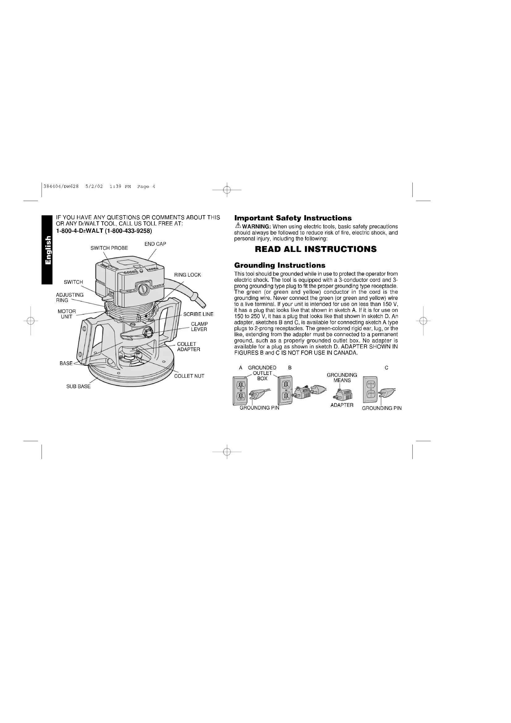
Grounding Instructions This tool should be grounded while in use to protect the operator from electric shock. The tool is equipped with a 3-conductor cord and 3- prong grounding type plug to fit the proper grounding type receptacle. The green (or green and yellow) conductor in the cord is the grounding wire. Never connect the green (or green and yellow) wire to a live terminal. If your unit is intended for use on less than 150 V, it has a plug that looks like that shown in sketch A. If it is for use on 150 to 250 V, it has a plug that looks like that shown in sketch D. An adapter, sketches B and C, is available for connecting sketch A type plugs to 2-prong receptacles. The green-colored rigid ear, lug, or the like, extending from the adapter must be connected to a permanent ground, such as a properly grounded outlet box. No adapter is available for a plug as shown in sketch D. ADAPTER SHOWN IN FIGURES B and C IS NOT FOR USE IN CANADA. English IF YOU HAVE ANY QUESTIONS OR COMMENTS ABOUT THIS
- KEEP WORK AREA CLEAN. Cluttered areas and benches invite injuries.
- CONSIDER WORK AREA ENVIRONMENT. Don’t expose power tools to rain. Don’t use power tools in damp or wet locations. Keep work area well lit. Do not use tool in presence of flammable liquids or gases.
- GUARD AGAINST ELECTRIC SHOCK. Prevent body contact with grounded surfaces. For example; pipes, radiators, ranges, and refrigerator enclosures.
- KEEP CHILDREN AWAY. Do not let visitors contact tool or extension cord. All visitors should be kept away from work area.
- STORE IDLE TOOLS. When not in use, tools should be stored in dry, and high or locked-up place — out of reach of children.
- DON’T FORCE TOOL. It will do the job better and safer at the rate for which it was intended.
- USE RIGHT TOOL. Don’t force small tool or attachment to do the job of a heavy-duty tool. Don’t use tool for purpose not intended.
- DRESS PROPERLY. Do not wear loose clothing or jewelry. They can be caught in moving parts. Rubber gloves and non-skid footwear are recommended when working outdoors. Wear protective hair covering to contain long hair.
- USE SAFETY GLASSES. Also use face or dust mask if cutting operation is dusty.
- DON’T ABUSE CORD. Never carry tool by cord or yank it to disconnect from receptacle. Keep cord from heat, oil, and sharp edges.
- SECURE WORK. Use clamps or a vise to hold work. It’s safer than using your hand and it frees both hands to operate tool.
- DON’T OVERREACH. Keep proper footing and balance at all times.
- MAINTAIN TOOLS WITH CARE. Keep tools sharp and clean for better and safer performance. Follow instructions for lubricating and changing accessories. Inspect tool cords periodically and if damaged, have repaired by authorized service facility. Inspect extension cords periodically and replace if damaged. Keep handles dry, clean, and free from oil and grease.
- DISCONNECT OR LOCK OFF TOOLS when not in use, before servicing, and when changing accessories, such as blades, bits, cutters.
- REMOVE ADJUSTING KEYS AND WRENCHES. Form habit of checking to see that keys and adjusting wrenches are removed from tool before turning it on.
- AVOID UNINTENTIONAL STARTING. Don’t carry tool with finger on switch. Be sure switch is off when plugging in.
- EXTENSION CORDS. Use only 3-wire extension cords that have 3-prong grounding-type plugs and 3-pole receptacles that accept the tool’s plug. Replace or repair damaged cords. Make sure your extension cord is in good condition. When using an extension cord, be sure to use one heavy enough to carry the current your product will draw. An undersized cord will cause a drop in line voltage resulting in loss of power and overheating. The following table shows the correct size to use depending on cord length and nameplate ampere rating. If in doubt, use the next heavier gage. The smaller the gage number, the heavier the cord. Minimum Gage for Cord Sets Volts Total Length of Cord in Feet 120V 0-25 26-50 51-100 101-150 240V 0-50 51-100 101-200 201-300 Ampere Rating More Not more American Wire Gage (AWG) Than Than
- OUTDOOR USE EXTENSION CORDS. When tool is used outdoors, use only extension cords intended for use outdoors and
English 384404/DW628 5/2/02 1:39 PM Page 1removing the motor unit from the base. ALWAYS BE SURE THAT THE CLAMP LEVER IS IN THE LOCKED (DOWN) POSITION WHEN ROUTING. The orientation of the lever can be changed if desired by loosening the lock nut that fastens it to the router and rotating the lever to the desired position. Retighten the lock nut. Sub Base Turn Off and Unplug Router The sub base on your router has been specifically designed to permit better visibility than conventional routers but retain the ability to use template guides. The guide adapter, if not needed, can be easily removed for even more visibility. To remove the adapter raise the Clamp Lever and lift the motor assembly out of the router base. This will enable you to reach and remove the two screws in the base which hold the guide adapter in place, as shown in Figure 2. When you reinstall the motor unit, be sure to align the Guide Screw (Figure 3) with the slot in the router base. LOCKING LEVER
- STAY ALERT. Watch what you are doing. Use common sense. Do not operate tool when you are tired.
- CHECK DAMAGED PARTS. Before further use of the tool, a guard or other part that is damaged should be carefully checked to determine that it will operate properly and perform its intended function. Check for alignment of moving parts, binding of moving parts, breakage of parts, mounting, and any other conditions that may affect its operation. A guard or other part that is damaged should be properly repaired or replaced by an authorized service center unless otherwise indicated elsewhere in this instruction manual. Have defective switches replaced by authorized service center. Do not use tool if switch does not turn it on and off.
SAVE THESE INSTRUCTIONS
Motor Your DEWALT tool is powered by a DEWALT-built motor. Be sure your power supply agrees with the nameplate marking. 120 Volts 60Hz or “AC/DC” means your tool may be operating with alternating or direct current. Voltage decrease of more than 10% will cause loss of power and overheating. All D EWALT tools are factory tested; if this tool does not operate, check the power supply. Clamp Lever Turn Off and Unplug Router. In order to lock the position of the router motor unit in the router base, a lever has been provided on the side of the tool, as shown in Figure
To lock the motor unit in place, push the lever all the way down; to release the motor, raise the lever up to about a right angle to the tool. Use this loosened position for making depth adjustments and English FIG. 1 FIG. 2 SUB BASE GUIDE ADAPTER 384404/DW628 5/2/02 1:39 PM Page 2Sub Base Alignment For Template Routing The guide adapter is aligned with the collet at the time of manufacture, but the two may become misaligned during shipping and handling, particularly if the tool is dropped. To properly align the collet with the guide adapter follow the steps below.
1. Turn Off and Unplug Router.
2. Raise the Clamp Lever and remove the motor unit from the router
3. Remove the Guide Screw and the Adjusting Ring shown in Figure 3.
4. Loosen the 4 screws in the Sub Base, as shown in Figure 4.
5. Re-insert the Guide Screw (not the Adjusting Ring) in the motor
unit and insert the motor unit into the router base. (Make sure that you align the Guide Screw with the slot in the router base.)
6. Lower the motor unit until the collet adapter extends through the
guide adapter, as shown in Figure 4. Adjust the Sub Base until the collet adapter fits through it.
7. Tighten the four screws in the Sub Base and remove the motor
unit from the router base.
8. Remove the Guide Screw and re-install the Adjusting Ring.
9. Install the Guide Screw and re-insert the motor unit into the router
base. (Be sure to align the guide screw with the slot in the base.)
10. The template guide is now aligned with the collet.
NOTE: When installing the guide screw in the above section remember that it must be tightened firmly so that the head is flush against the side of the motor unit. Attaching Bits and Cutters Turn Off and Unplug Router Insert the shank of the desired bit or cutter into the collect as far as it will go, then pull it out slightly (about 1/32”,.793 mm). Use the wrenches provided to securely tighten the collet nut. One wrench holds the collet adapter and the other tightens the collet nut. A special coating has been put on the collet and collet nut to increase the bit holding power. Use only the wrenches provided with your router to tighten the collet nut. Other tools may damage the coating through overtightening. Depth Adjustment Turn Off and Unplug Router Loosen the Clamp Lever by raising it fully. Adjust the depth setting of the router bit by turning the Adjusting Ring shown in Figure 5. To raise the bit away from the work surface, turn the ring clockwise (as viewed from the top of the tool) and to lower the bit into the work, turn it counterclockwise.Directly over the Clamp Lever pivot point is a line scribed into the aluminum housing, as shown in Figure 5. As the ring is rotated, the raised lugs on the ring will pass over this line. Each time a lug passes the line, the bit is raised or lowered 1/64" (.396 mm). Every full revolution of the Adjusting Ring accounts for
English FIG. 3 GUIDE SCREW ADJUSTING RING GUIDE ADAPTER COLLET ADAPTER FIG. 4 SCREWS 384404/DW628 5/2/02 1:39 PM Page 31/8"(3.175 mm) of adjustment either up or down. The lugs are consecutively numbered for convenience. For faster adjustments, lift the motor housing slightly and spin the Adjusting Ring. Duplicating specific depths of cut, such as hinge butt mortises, can be done quickly and accurately by following the steps below.
1. TURN OFF AND UNPLUG ROUTER.
2. Lower the router bit until it just touches the workpiece. (Refer to
preceding section on “DEPTH ADJUSTMENT.”)
3. Lock the Clamp Lever
4. Raise the Adjusting Ring by rotating it counterclockwise until the
hinge will just fit between the top edge of the router base and the bottom of the Adjusting Ring, as shown in Figure 6.
5. Remove the hinge and invert the router to prevent the bit from
marring the work surface.
6. Unlock the Clamp Lever and allow the base to fall to the new
setting. Lock the Clamp Lever in place and the depth is set. The router will now cut to the exact thickness of the hinge. Adjusting Ring Lock Turn Off and Unplug Router. To prevent the Adjusting Ring from rotating due to vibration of the router, a nylon set screw has been provided in the ring. When the ring is set as desired, tighten this set screw, shown in Figure 7. Be careful to avoid overtightening which will strip the soft nylon screw. The set screw can be used whenever desired, or never at all. On/Off Switch The on/off switch is located on the side of the router, just above the hand grip, Figure 8. To turn on the router, raise the on/off switch lever with your thumb while gripping the tool. To turn off the router, pull the switch lever down. When the router is running, you will notice a probe
English FIG. 7 OFF OFF FIG. 5 FIG. 6 CLAMP LEVER ADJUSTING RING HINGE NYLON RING LOCK 384404/DW628 5/2/02 1:39 PM Page 4extending from the top of the router. This probe is connected to the on/off switch lever and can be used to turn off the router by pushing it down toward the end cap. This probe also prevents the router from inadvertently being turned on while it is inverted and resting on its end cap. The end cap is designed so that the router can be inverted for temporary storage, when changing the work piece, and while changing router bits. Figure 9. CAUTION: Some wood contains preservatives such as copper chromium arsenate (CCA) which can be toxic. When cutting or sanding these materials extra care should be taken to avoid inhalation and minimize skin contact. Accessories Recommended accessories for use with your tool are available at extra cost from your local dealer or authorized service center. If you need assistance in locating any accessory for your tool, call us toll free at: 1-800-4-D EWALT (1-800-433-9258) or contact: DEWALT Industrial Tool Company 626 Hanover Pike, P.O. Box 158 Hampstead, MD. 21074-0158 CAUTION: The use of any other accessory not recommended for use with this tool could be hazardous. Important To assure product SAFETY and RELIABILITY, repairs, maintenance and adjustment (including brush inspection and replacement) should be performed by authorized service centers or other qualified service organizations, always using identical replacement parts. Full Warranty DEWALT heavy duty industrial tools are warranted for one year from date of purchase. We will repair, without charge, any defects due to faulty materials or workmanship. For warranty repair information, call 1-800-4-D EWALT. This warranty does not apply to accessories or damage caused where repairs have been made or attempted by others. This warranty gives you specific legal rights and you may have other rights which vary in certain states or provinces. In addition to the warranty, D EWALT tools are covered by our:
30 DAY NO RISK SATISFACTION GUARANTEE
If you are not completely satisfied with the performance of your
EWALT heavy duty industrial tool, simply return it to the participating seller within 30 days for a full refund. Please return the complete unit, transportation prepaid. Proof of purchase may be required.