DCS520T2RQW - Saw DEWALT - Free user manual and instructions
Find the device manual for free DCS520T2RQW DEWALT in PDF.
Download the instructions for your Saw in PDF format for free! Find your manual DCS520T2RQW - DEWALT and take your electronic device back in hand. On this page are published all the documents necessary for the use of your device. DCS520T2RQW by DEWALT.
USER MANUAL DCS520T2RQW DEWALT
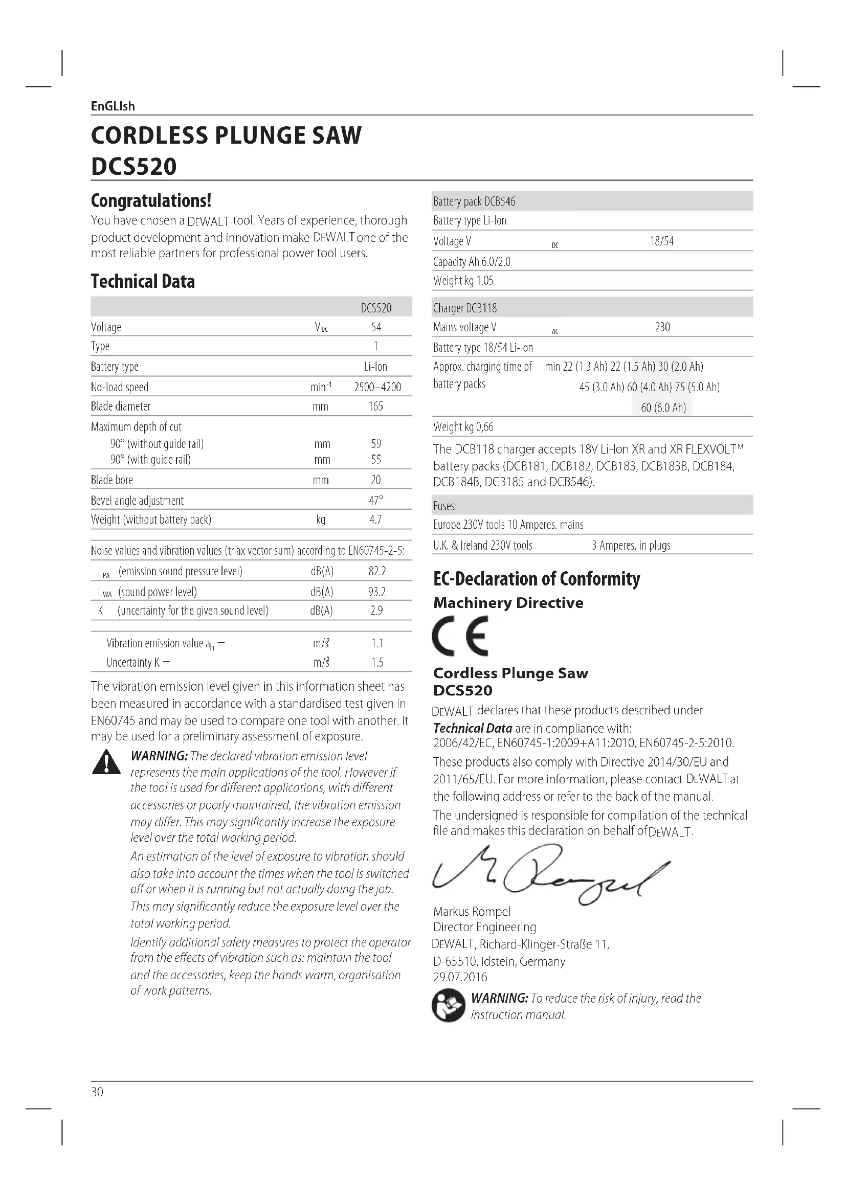
battery packs (DCB181, DCB182, DCB183, DCB183B, DCB184, DCB184B, DCB185 and DCB546). Fuses: Europe 230V tools 10 Amperes. mains U.K. & Ireland 230V tools 3 Amperes. in plugs EC-Declaration of Conformity Machinery Directive Cordless Plunge Saw DCS520 DeWALT declares that these products described under Technical Data are in compliance with: 2006/42/EC, EN60745-1:2009+A11:2010, EN60745-2-5:2010. These products also comply with Directive 2014/30/EU and 2011/65/EU. For more information, please contact DeWALT
the following address or refer to the back of themanual. The undersigned is responsible for compilation of the technical file and makes this declaration on behalf of DeWALT
WARNING: To reduce the risk of injury, read the
instruction manual. English (original instructions)
DCS520 Congratulations! You have chosen a DeWALT tool. Years of experience, thorough product development and innovation make DeWALT one of the most reliable partners for professional power toolusers. Technical Data DCS520 Voltage V
2500–4200 Blade diameter mm 165 Maximum depth of cut 90° (without guide rail) 90° (with guide rail)
Blade bore mm 20 Bevel angle adjustment 47° Weight (without battery pack) kg 4.7 Noise values and vibration values (triax vector sum) according to EN60745-2-5:
(emission sound pressure level) dB(A) 82.2
(sound power level) dB(A) 93.2 K (uncertainty for the given sound level) dB(A) 2.9 Vibration emission value a
The vibration emission level given in this information sheet has been measured in accordance with a standardised test given in EN60745 and may be used to compare one tool with another. It may be used for a preliminary assessment ofexposure.
WARNING: The declared vibration emission level
represents the main applications of the tool. However if the tool is used for different applications, with different accessories or poorly maintained, the vibration emission may differ. This may significantly increase the exposure level over the total workingperiod. An estimation of the level of exposure to vibration should also take into account the times when the tool is switched off or when it is running but not actually doing the job. This may significantly reduce the exposure level over the total workingperiod. Identify additional safety measures to protect the operator from the effects of vibration such as: maintain the tool and the accessories, keep the hands warm, organisation of workpatterns.31 EnGLIsh Definitions: Safety Guidelines The definitions below describe the level of severity for each signal word. Please read the manual and pay attention to thesesymbols.
DANGER: Indicates an imminently hazardous
situation which, if not avoided, will result in death or seriousinjury.
WARNING: Indicates a potentially hazardous situation
which, if not avoided, could result in death or seriousinjury.
CAUTION: Indicates a potentially hazardous situation which, if not avoided, may result in minor or moderateinjury. NOTICE: Indicates a practice not related to personal injury which, if not avoided, may result in propertydamage.
Denotes risk of electricshock.
Denotes risk offire. General Power Tool Safety Warnings
WARNING: Read all safety warnings and all
instructions. Failure to follow the warnings and instructions may result in electric shock, fire and/or seriousinjury.
The term “power tool” in the warnings refers to your mains- operated (corded) power tool or battery-operated (cordless) powertool.
a ) Keep work area clean and well lit. Cluttered or dark areas inviteaccidents. b ) Do not operate power tools in explosive atmospheres, such as in the presence of flammable liquids, gases or dust. Power tools create sparks which may ignite the dust orfumes. c ) Keep children and bystanders away while operating a power tool. Distractions can cause you to losecontrol.
2) Electrical safety
a ) Power tool plugs must match the outlet. Never modify the plug in any way. Do not use any adapter plugs with earthed (grounded) power tools. Unmodified plugs and matching outlets will reduce risk of electricshock. b ) Avoid body contact with earthed or grounded surfaces such as pipes, radiators, ranges and refrigerators. There is an increased risk of electric shock if your body is earthed orgrounded. c ) Do not expose power tools to rain or wet conditions. Water entering a power tool will increase the risk of electricshock. d ) Do not abuse the cord. Never use the cord for carrying, pulling or unplugging the power tool. Keep cord away from heat, oil, sharp edges or moving parts. Damaged or entangled cords increase the risk of electricshock. e ) When operating a power tool outdoors, use an extension cord suitable for outdoor use. Use of a cord suitable for outdoor use reduces the risk of electricshock. f ) If operating a power tool in a damp location is unavoidable, use a residual current device (RCD) protected supply. Use of an RCD reduces the risk of electricshock.
a ) Stay alert, watch what you are doing and use common sense when operating a power tool. Do not use a power tool while you are tired or under the influence of drugs, alcohol or medication. A moment of inattention while operating power tools may result in serious personalinjury. b ) Use personal protective equipment. Always wear eye protection. Protective equipment such as dust mask, non-skid safety shoes, hard hat, or hearing protection used for appropriate conditions will reduce personalinjuries. c ) Prevent unintentional starting. Ensure the switch is in the off position before connecting to power source and/or battery pack, picking up or carrying the tool. Carrying power tools with your finger on the switch or energising power tools that have the switch on invitesaccidents. d ) Remove any adjusting key or wrench before turning the power tool on. A wrench or a key left attached to a rotating part of the power tool may result in personalinjury. e ) Do not overreach. Keep proper footing and balance at all times. This enables better control of the power tool in unexpectedsituations. f ) Dress properly. Do not wear loose clothing or jewellery. Keep your hair, clothing and gloves away from moving parts. Loose clothes, jewellery or long hair can be caught in movingparts. g ) If devices are provided for the connection of dust extraction and collection facilities, ensure these are connected and properly used. Use of dust collection can reduce dust-relatedhazards.
4) Power tool use and care
a ) Do not force the power tool. Use the correct power tool for your application. The correct power tool will do the job better and safer at the rate for which it wasdesigned. b ) Do not use the power tool if the switch does not turn it on and off. Any power tool that cannot be controlled with the switch is dangerous and must berepaired. c ) Disconnect the plug from the power source and/or the battery pack from the power tool before making any adjustments, changing accessories, or storing32 EnGLIsh power tools. Such preventive safety measures reduce the risk of starting the power toolaccidentally. d ) Store idle power tools out of the reach of children and do not allow persons unfamiliar with the power tool or these instructions to operate the power tool. Power tools are dangerous in the hands of untrainedusers. e ) Maintain power tools. Check for misalignment or binding of moving parts, breakage of parts and any other condition that may affect the power tool’s operation. If damaged, have the power tool repaired before use. Many accidents are caused by poorly maintained powertools. f ) Keep cutting tools sharp and clean. Properly maintained cutting tools with sharp cutting edges are less likely to bind and are easier tocontrol. g ) Use the power tool, accessories and tool bits etc., in accordance with these instructions taking into account the working conditions and the work to be performed. Use of the power tool for operations different from those intended could result in a hazardoussituation.
5) Battery tool use and care
a ) Recharge only with the charger specified by the manufacturer. A charger that is suitable for one type of battery pack may create a risk of fire when used with another batterypack. b ) Use power tools only with specifically designated battery packs. Use of any other battery packs may create a risk of injury andfire. c ) When battery pack is not in use, keep it away from other metal objects like paper clips, coins, keys, nails, screws or other small metal objects that can make a connection from one terminal to another. Shorting the battery terminals together may cause burns or afire. d ) Under abusive conditions, liquid may be ejected from the battery; avoid contact. If contact accidentally occurs, flush with water. If liquid contacts eyes, additionally seek medical help. Liquid ejected from the battery may cause irritation orburns.
a ) Have your power tool serviced by a qualified repair person using only identical replacement parts. This will ensure that the safety of the power tool ismaintained. Additional Specific Safety Rules Safety Instructions for All Saws a ) DANGER: Keep hands away from cutting area and the blade. Keep your second hand on auxiliary handle, or motor housing. If both hands are holding the saw, they cannot be cut by the blade. b ) Do not reach underneath the workpiece. The guard cannot protect you from the blade below the workpiece. c ) Adjust the cutting depth to the thickness of the workpiece. Less than a full tooth of the blade teeth should be visible below the workpiece. d ) Never hold piece being cut in your hands or across your leg. Secure the workpiece to a stable platform. It is important to support the work properly to minimize body exposure, blade binding, or loss of control. e ) Hold power tool by insulated gripping surfaces when performing an operation where the cutting tool may contact hidden wiring. Contact with a "live" wire will also make exposed metal parts of the power tool "live" and shock the operator. f ) When ripping always use a rip fence or straight edge guide. This improves the accuracy of cut and reduces the chance of blade binding. g ) Always use blades with correct size and shape (diamond versus round) of arbour holes. Blades that do not match the mounting hardware of the saw will run eccentrically, causing loss of control. h ) Never use damaged or incorrect blade washers or bolt. The blade washers and bolt were specially designed for your saw, for optimum performance and safety of operation. Causes and Operator Prevention of Kickback
- Kickback is a sudden reaction to a pinched, bound or misaligned saw blade, causing an uncontrolled saw to lift up and out of the workpiece toward the operator;
- When the blade is pinched or bound tightly by the kerf closing down, the blade stalls and the motor reaction drives the unit rapidly back toward the operator;
- If the blade becomes twisted or misaligned in the cut, the teeth at the back edge of the blade can dig into the top surface of the wood causing the blade to climb out of the kerf and jump back toward the operator. Kickback is the result of saw misuse and/or incorrect operating procedures or conditions and can be avoided by taking proper precautions as given below: a ) Maintain a firm grip with both hands on the saw and position your arms to resist kickback forces. Position your body to either side of the blade, but not in line with the blade. Kickback could cause the saw to jump backwards, but kickback forces can be controlled by the operator, if proper precautions are taken. b ) When blade is binding, or when interrupting a cut for any reason, release the trigger and hold the saw motionless in the material until the blade comes to a complete stop. Never attempt to remove the saw from the work or pull the saw backward while the blade is in motion or kickback may occur. Investigate and take corrective actions to eliminate the cause of bladebinding. c ) When restarting a saw in the workpiece, centre the saw blade in the kerf and check that saw teeth are33 EnGLIsh not engaged into the material. If saw blade is binding, it may walk up or kickback from the workpiece as the saw is restarted. d ) Support large panels to minimise the risk of blade pinching and kickback. Large panels tend to sag under their own weight. Supports must be placed under the panel on both sides, near the line of cut and near the edge of the panel. e ) Do not use dull or damaged blades. Unsharpened or improperly set blades produce narrow kerf causing excessive friction, blade binding and kickback. f ) Blade depth and bevel adjusting locking levers must be tight and secure before making cut. If blade adjustment shifts while cutting, it may cause binding andkickback. g ) Use extra caution when making a “plunge cut” into existing walls or other blind areas. The protruding blade may cut objects that can cause kickback. Safety Instructions for Plunge-Type Saws a ) Check guard for proper closing before each use. Do not operate the saw if guard does not move freely and enclose the blade instantly. Never clamp or tie the guard with the blade exposed. If saw is accidentally dropped, guard may be bent. Check to make sure that guard moves freely and does not touch the blade or any other part, in all angles and depths of cut. b ) Check the operation and condition of the guard return spring. If the guard and the spring are not operating properly, they must be serviced before use. Guard may operate sluggishly due to damaged parts, gummy deposits, or a build-up of debris. c ) Assure that the guide plate of the saw will not shift while performing the “plunge cut” when the blade bevel setting is not at 90°. Blade shifting sideways will cause binding and likely kickback. d ) Always observe that the guard is covering the blade before placing saw down on bench or floor. An unprotected, coasting blade will cause the saw to walk backwards, cutting whatever is in its path. Be aware of the time it takes for the blade to stop after switch is released. Additional Safety Instructions for All Saws with Riving Knife a ) Use the appropriate riving knife for the blade being used. For the riving knife to work, it must be thicker than the body of the blade but thinner than the tooth set of the blade. b ) Adjust the riving knife as described in this instruction manual. Incorrect spacing, positioning and alignment can make the riving knife ineffective in preventingkickback. c ) For the riving knife to work, it must be engaged in the workpiece. The riving knife is ineffective in preventing kickback during short cuts. d ) Do not operate the saw if riving knife is bent. Even a light interference can slow the closing rate of a guard. Additional Safety Instructions for Plunge- Type Saws
- Wear ear protectors. Exposure to noise can cause hearing loss.
- Wear a dust mask. Exposure to dust particles can cause breathing difficulty and possible injury.
- Do not use blades of larger or smaller diameter than recommended. For the proper blade rating refer to the technical data. Use only the blades specified in this manual, complying with EN 847-1.
- Never use abrasive cut-off wheels. Residual Risks In spite of the application of the relevant safety regulations and the implementation of safety devices, certain residual risks cannot be avoided. These are:
- Impairment ofhearing.
- Risk of personal injury due to flyingparticles.
- Risk of burns due to accessories becoming hot duringoperation.
- Risk of personal injury due to prolongeduse. Electrical Safety The electric motor has been designed for one voltage only. Always check that the battery pack voltage corresponds to the voltage on the rating plate. Also make sure that the voltage of your charger corresponds to that of yourmains. Your DeWALT charger is double insulated in accordance with EN60335; therefore no earth wire isrequired. If the supply cord is damaged, it must be replaced by a specially prepared cord available through the DeWALT
serviceorganisation. Mains Plug Replacement (U.K. & Ireland Only) If a new mains plug needs to be fitted:
- Safely dispose of the oldplug.
- Connect the brown lead to the live terminal in theplug.
- Connect the blue lead to the neutralterminal.
WARNING: No connection is to be made to the
earthterminal. Follow the fitting instructions supplied with good quality plugs. Recommended fuse: 3A. Using an Extension Cable An extension cord should not be used unless absolutely necessary. Use an approved extension cable suitable for the power input of your charger (see Technical Data). The minimum conductor size is 1mm
SAVE THESE INSTRUCTIONS
Chargers DeWALT chargers require no adjustment and are designed to be as easy as possible tooperate. Important Safety Instructions for All Battery Chargers SAVE THESE INSTRUCTIONS: This manual contains important safety and operating instructions for compatible battery chargers (refer to TechnicalData).
- Before using charger, read all instructions and cautionary markings on charger, battery pack, and product using batterypack.
WARNING: Shock hazard. Do not allow any liquid to get
WARNING: We recommend the use of a residual current
device with a residual current rating of 30mA orless.
CAUTION: Burn hazard. To reduce the risk of injury, charge only DeWALT rechargeable batteries. Other types of batteries may burst causing personal injury anddamage.
CAUTION: Children should be supervised to ensure that they do not play with theappliance. NOTICE: Under certain conditions, with the charger plugged into the power supply, the exposed charging contacts inside the charger can be shorted by foreign material. Foreign materials of a conductive nature such as, but not limited to, steel wool, aluminum foil or any buildup of metallic particles should be kept away from charger cavities. Always unplug the charger from the power supply when there is no battery pack in the cavity. Unplug charger before attempting to clean
- DO NOT attempt to charge the battery pack with any chargers other than the ones in this manual. The charger and battery pack are specifically designed to worktogether.
- These chargers are not intended for any uses other than charging DeWALT rechargeable batteries. Any other uses may result in risk of fire, electric shock orelectrocution.
- Do not expose charger to rain orsnow.
- Pull by plug rather than cord when disconnecting charger. This will reduce risk ofdamage to electric plug andcord.
- Make sure that cord is located so that it will not be stepped on, tripped over, or otherwise subjected to damage orstress.
- Do not use an extension cord unless it is absolutely necessary. Use of improper extension cord could result in risk of fire,electric shock, orelectrocution.
- Do not place any object on top of charger or place the charger on a soft surface that might block the ventilation slots and result in excessive internal heat. Place the charger in a position away from any heat source. The charger is ventilated through slots in the top and the bottom of thehousing.
- Do not operate charger with damaged cord or plug— have them replacedimmediately.
- Do not operate charger if it has received a sharp blow, been dropped, or otherwise damaged in any way. Take it to an authorised servicecentre.
- Do not disassemble charger; take it to an authorised service centre when service or repair is required. Incorrect reassembly may result in a risk of electric shock, electrocution orfire.
- In case of damaged power supply cord the supply cord must be replaced immediately by the manufacturer, its service agent or similar qualified person to prevent anyhazard.
- Disconnect the charger from the outlet before attempting any cleaning. This will reduce the risk of electric shock. Removing the battery pack will not reduce thisrisk.
- NEVER attempt to connect two chargerstogether.
- The charger is designed to operate on standard 230V household electrical power. Do not attempt to use it on any other voltage. This does not apply to the vehicularcharger. Charging a Battery (Fig. A)
1. Plug the charger into an appropriate outlet before inserting
into the charger, making sure the battery pack is fully seated in the charger. The red (charging) light will blink repeatedly indicating that the charging process has started.
3. The completion of charge will be indicated by the red
light remaining ON continuously. The battery pack is fully charged and may be used at this time or left in the charger. To remove the battery pack from the charger, push the battery release button
on the battery pack. nOTE: To ensure maximum performance and life of lithium-ion battery packs, charge the battery pack fully before first use. Charger Operation Refer to the indicators below for the charge status of the battery pack. Charge Indicators Charging Fully Charged Hot/Cold Pack Delay*
- The red light will continue to blink, but a yellow indicator light will be illuminated during this operation. Once the battery pack has reached an appropriate temperature, the yellow light will turn off and the charger will resume the charging procedure. The compatible charger(s) will not charge a faulty battery pack. The charger will indicate faulty battery by refusing to light or by displaying problem pack or charger blink pattern. nOTE: This could also mean a problem with a charger. If the charger indicates a problem, take the charger and battery pack to be tested at an authorised service centre.35 ENGLISH Hot/Cold Pack Delay When the charger detects a battery pack that is too hot or too cold, it automatically starts a Hot/Cold Pack Delay, suspending charging until the battery pack has reached an appropriate temperature. The charger then automatically switches to the pack charging mode. This feature ensures maximum battery pack life. A cold battery pack will charge at a slower rate than a warm battery pack. The battery pack will charge at that slower rate throughout the entire charging cycle and will not return to maximum charge rate even if the battery pack warms. The DCB118 charger is equipped with an internal fan designed to cool the battery pack. The fan will turn on automatically when the battery pack needs to be cooled. Never operate the charger if the fan does not operate properly or if ventilation slots are blocked. Do not permit foreign objects to enter the interior of the charger. Electronic Protection System XR Li-Ion tools are designed with an Electronic Protection System that will protect the battery pack against overloading, overheating or deep discharge. The tool will automatically turn off if the Electronic Protection System engages. If this occurs, place the lithium-ion battery pack on the charger until it is fully charged. Wall Mounting These chargers are designed to be wall mountable or to sit upright on a table or work surface. If wall mounting, locate the charger within reach of an electrical outlet, and away from a corner or other obstructions which may impede air flow. Use the back of the charger as a template for the location of the mounting screws on the wall. Mount the charger securely using drywall screws (purchased separately) at least 25.4mm long with a screw head diameter of 7–9mm, screwed into wood to an optimal depth leaving approximately 5.5mm of the screw exposed. Align the slots on the back of the charger with the exposed screws and fully engage them in the slots. Charger Cleaning Instructions
WARNING: Shock hazard. Disconnect the charger
from the AC outlet before cleaning. Dirt and grease may be removed from the exterior of the charger using a cloth or soft non-metallic brush. Do not use water or any cleaning solutions. Never let any liquid get inside the tool; never immerse any part of the tool into a liquid. Battery Packs Important Safety Instructions for All Battery Packs When ordering replacement battery packs, be sure to include catalog number and voltage. The battery pack is not fully charged out of the carton. Before using the battery pack and charger, read the safety instructions below. Then follow charging procedures outlined.
READ ALL INSTRUCTIONS
- Do not charge or use battery in explosive atmospheres, such as in the presence of flammable liquids, gases or dust. Inserting or removing the battery from the charger may ignite the dust or fumes.
- Never force battery pack into charger. Do not modify battery pack in any way to fit into a non-compatible charger as battery pack may rupture causing serious personal injury.
- Charge the battery packs only in DeWALT chargers.
- DO NOT splash or immerse in water or other liquids.
- Do not store or use the tool and battery pack in locations where the temperature may reach or exceed 40 ˚C (104 ˚F) (such as outside sheds or metal buildings in summer).
- Do not incinerate the battery pack even if it is severely damaged or is completely worn out. The battery pack can explode in a fire. Toxic fumes and materials are created when lithium-ion battery packs are burned.
- If battery contents come into contact with the skin, immediately wash area with mild soap and water. If battery liquid gets into the eye, rinse water over the open eye for 15 minutes or until irritation ceases. If medical attention is needed, the battery electrolyte is composed of a mixture of liquid organic carbonates and lithium salts.
- Contents of opened battery cells may cause respiratory irritation. Provide fresh air. If symptoms persists, seek medical attention.
WARNING: Burn hazard. Battery liquid may be flammable
if exposed to spark or flame.
WARNING: Never attempt to open the battery pack for
any reason. If battery pack case is cracked or damaged, do not insert into charger. Do not crush, drop or damage battery pack. Do not use a battery pack or charger that has received a sharp blow, been dropped, run over or damaged in any way (i.e., pierced with a nail, hit with a hammer, stepped on). Electric shock or electrocution may result. Damaged battery packs should be returned to service centre for recycling.
WARNING: Fire hazard. Do not store or carry the
battery pack so that metal objects can contact exposed battery terminals. For example, do not place the battery pack in aprons, pockets, tool boxes, product kit boxes, drawers, etc., with loose nails, screws, keys, etc.
CAUTION: When not in use, place tool on its side on a stable surface where it will not cause a tripping or falling hazard. Some tools with large battery packs will stand upright on the battery pack but may be easily knocked over. Transportation
WARNING: Fire hazard. Transporting batteries can
possibly cause fire if the battery terminals inadvertently come in contact with conductive materials. When transporting batteries, make sure that the battery terminals are protected and well insulated from materials that could contact them and cause a short circuit.36 ENGLISH DeWALT batteries comply with all applicable shipping regulations as prescribed by industry and legal standards which include UN Recommendations on the Transport of Dangerous Goods; International Air Transport Association (IATA) Dangerous Goods Regulations, International Maritime Dangerous Goods (IMDG) Regulations, and the European Agreement Concerning The International Carriage of Dangerous Goods by Road (ADR). Lithium-ion cells and batteries have been tested to section 38.3 of the UN Recommendations on the Transport of Dangerous Goods Manual of Tests and Criteria. In most instances, shipping a DeWALT battery pack will be excepted from being classified as a fully regulated Class 9 Hazardous Material. In general, only shipments containing a lithium-ion battery with an energy rating greater than 100 Watt Hours (Wh) will require being shipped as fully regulated Class 9. All lithium-ion batteries have the Watt Hour rating marked on the pack. Furthermore, due to regulation complexities, DeWALT
does not recommend air shipping lithium-ion battery packs alone regardless of Watt Hour rating. Shipments of tools with batteries (combo kits) can be air shipped as excepted if the Watt Hour rating of the battery pack is no greater than 100 Whr. Regardless of whether a shipment is considered excepted or fully regulated, it is the shipper's responsibility to consult the latest regulations for packaging, labeling/marking and documentation requirements. The information provided in this section of the manual is provided in good faith and believed to be accurate at the time the document was created. However, no warranty, expressed or implied, is given. It is the buyer’s responsibility to ensure that its activities comply with the applicable regulations. Transporting the FLEXVOLT
Battery The DeWALT FLEXVOLT
battery has two modes: Use and Transport. Use Mode: When the FLEXVOLT
battery stands alone or is in
DeWALT 18V product, it will operate as an 18V battery. When the FLEXVOLT
battery is in a 54V or a 108V (two 54V batteries) product, it will operate as a 54V battery. Transport Mode: When the cap is attached to the FLEXVOLT
battery, the battery is in transport mode. Keep the cap for shipping. When in Transport mode, strings of cells are electrically disconnected within the pack resulting in 3 batteries with a lower Watt hour (Wh) rating as compared to 1 battery with a higher Watt hour rating. This increased quantity of 3 batteries with the lower Watt hour rating can exempt the pack from certain shipping regulations that are imposed upon the higher Watt hour batteries. For example, the Transport Wh rating might indicate 3x36 Wh, meaning 3 batteries of 36 Wh each. The Use Wh rating might indicate 108 Wh (1 battery implied). Example of Use and Transport Label Marking Storage Recommendations
1. The best storage place is one that is cool and dry away
from direct sunlight and excess heat or cold. For optimum battery performance and life, store battery packs at room temperature when not in use.
2. For long storage, it is recommended to store a fully charged
battery pack in a cool, dry place out of the charger for optimal results. NOTE: Battery packs should not be stored completely depleted of charge. The battery pack will need to be recharged before use. Labels on Charger and Battery Pack In addition to the pictographs used in this manual, the labels on the charger and the battery pack may show the following pictographs: Read instruction manual before use. See Technical Data for charging time. Do not probe with conductive objects. Do not charge damaged battery packs. Do not expose to water. Have defective cords replaced immediately. Charge only between 4 ˚C and 40 ˚C. Only for indoor use. Discard the battery pack with due care for the environment. Charge DeWALT battery packs only with designated DeWALT chargers. Charging battery packs other than the designated DeWALT batteries with a DeWALT charger may make them burst or lead to other dangerous situations. Do not incinerate the battery pack. USE (without transport cap). Example: Wh rating indicates 108 Wh (1 battery with 108 Wh). TRANSPORT (with built-in transport cap). Example: Wh rating indicates 3 x 36 Wh (3batteries of 36 Wh).37 ENGLISH Battery Type The DCS520 operates on a 54 volt battery pack. The DCB546 battery pack may be used. Refer to Technical Data for moreinformation. Package Contents The package contains: 1 Plunge saw 1 Hex wrench 1 Li-Ion battery pack (T1 models) 2 Li-Ion battery packs (T2 models) 3 Li-Ion battery packs (T3 models) 1 Instruction manual
- Check for damage to the tool, parts or accessories which may have occurred duringtransport.
- Take the time to thoroughly read and understand this manual prior tooperation. Markings on Tool The following pictograms are shown on the tool: Read instruction manual before use. Wear ear protection. Wear eye protection. Maximum depth of cut Blade diameter Date Code Position (Fig. A) The date code
, which also includes the year of manufacture, is printed into thehousing. Example: 2016 XX XX Year of Manufacture Description (Fig. A)
WARNING: Never modify the power tool or any part of it.
Damage or personal injury couldresult.
Rail adjustment knobs
Battery release button
Fuel gauge Intended Use The DCS520 cordless plunge saw is designed for professional sawing of wood products. DO NOT use under wet conditions or in the presence of flammable liquids orgases. This heavy-duty plunge saw is a professional power tool. DO NOT let children come into contact with the tool. Supervision is required when inexperienced operators use thistool.
- Young children and the infirm. This appliance is not intended for use by young children or infirm persons without supervision.
- This product is not intended for use by persons (including children) suffering from diminished physical, sensory or mental abilities; lack of experience, knowledge or skills unless they are supervised by a person responsible for their safety. Children should never be left alone with thisproduct.
ASSEMBLY AND ADJUSTMENTS
WARNING: To reduce the risk of serious personal
injury, turn tool off and disconnect battery pack before making any adjustments or removing/ installing attachments or accessories. An accidental start-up can causeinjury.
DeWALT battery packs andchargers. Inserting and Removing the Battery Pack from the Tool (Fig. A) NOTE: Make sure your battery pack
is fullycharged. To Install the Battery Pack into the Tool
with the rails as shown in FigureA.
2. Slide it in until the battery pack is firmly seated in the tool
and ensure that you hear it snap intoplace. To Remove the Battery Pack from the Tool
1. Press the release button
and firmly pull the battery packout.
2. Insert battery pack into the charger as described in the
charger section of thismanual.38 EnGLIsh Fuel Gauge Battery Packs (Fig. A) Some DeWALT battery packs include a fuel gauge which consists of three green LED lights that indicate the level of charge remaining in the batterypack. To actuate the fuel gauge, press and hold the fuel gauge button
. A combination of the three green LED lights will illuminate designating the level of charge left. When the level of charge in the battery is below the usable limit, the fuel gauge will not illuminate and the battery will need to berecharged. nOTE: The fuel gauge is only an indication of the charge left on the battery pack. It does not indicate tool functionality and is subject to variation based on product components, temperature and end-userapplication. Bevel Adjustment (Fig. A) The bevel angle can be adjusted between 0° and 47°.
2. Set the bevel angle by tilting the saw shoe
until the mark indicates the desired angle on the bevel scale
Changing the Saw Blade (Fig. A–C) nOTE: It is not necessary to remove the outer blade cover
to change the blade.
1. Remove the battery pack.
3. Press the plunge saw down until it stops (blade
clockwise until it stops.
down and using the hex wrench found in the front handle
, rotate the blade until the lock position is found. nOTE: The blade
is now locked and cannot be turned by hand.
6. Use the hex wrench to turn the blade clamping screw
anti-clockwise to remove.
and blade clamping screw
Turn the screw clockwise by hand. nOTE: The direction of rotation of the saw blade and the rotation of the plunge saw MUST be the same.
10. Release and turn the spindle lock lever
anti-clockwise until it stops.
11. Move the plunge saw back to top position.
forward, to take the saw out of blade change mode. Adjusting the Riving Knife (Fig. A–C) For the correct adjustment of the riving knife
, refer to FigureC. Adjust the clearance of the riving knife after changing the saw blade or whenever necessary.
1. Follow Changing the Saw Blade steps 1–5.
2. Loosen the riving knife adjustment screw
with a hex wrench and set the riving knife as shown in FigureC.
3. Tighten the riving knife adjustment screw
anti-clockwise until it stops.
5. Move the plunge saw back to top position.
forward, to take the saw out of blade change mode. Depth of Cut Adjustment (Fig. D) The cutting depth can be set at 0–59 mm without guide rail attached; with the guide rail attached: 0–55 mm.
and move the pointer to obtain the correct depth of cut.
nOTE: For optimal results, allow the saw blade to protrude from the workpiece by about 3 mm (Fig.D). OPERATION Instructions for Use
WARNING: Always observe the safety instructions and
applicableregulations.
WARNING: To reduce the risk of serious personal
injury, turn tool off and disconnect battery pack before making any adjustments or removing/ installing attachments or accessories. An accidental start-up can causeinjury. Proper Hand Position (Fig. E)
WARNING: To reduce the risk of serious personal injury,
WARNING: To reduce the risk of serious personal
injury, ALWAYS hold securely in anticipation of a suddenreaction. Proper hand position requires one hand on the front handle
with the other hand on the main handle
Switching On and Off (Fig. A) Press the on/off switch
to turn the plunge saw on. Guiding the Tool (Fig. A, E, F)
- ALWAYS secure the workpiece in such a manner that it cannot move while sawing.
- ALWAYS push the machine forward. NEVER pull the machine backward towards you.
- ALWAYS use the plunge saw with both hands. Put one hand on the main handle
and the second hand on the front handle
as shown in FigureE.
- ALWAYS use the clamp to hold the rail to the workpiece.
- Use proper hand position to guide the saw properly.
- The cutting indicator
displays the cutting line for 0° and 47° cuts (without guide rail).39 EnGLIsh
shows the blade position for full plunge.
- For optimum results, clamp the workpiece bottom up. Cutting
1. Place the machine with the front part of the saw shoe
3. Press the saw down to set cutting depth and push it forward
in the cutting direction. Plunge Cuts
WARNING: To avoid kickbacks, the following instructions
MUST be observed when plunge cutting:
- Place the machine onto the guide rail and release the anti-kickback knob
by turning it anti-clockwise.
- Turn the machine on and slowly press the saw down onto the set cutting depth and push forward in the cutting direction. The cutting indicators
display the absolute front and the absolute rear cutting points of the saw blade (dia. 165 mm) at maximum cutting depth and using the guide rail.
- If kickback happened during the plunge cut, turn the anti-kickback knob
anti-clockwise to release it from the rail.
- When you have finished the plunge cut, turn the anti- kickback knob
, which are available in different lengths, allow for precise, clean cuts and simultaneously protect the workpiece surface against damage. In conjunction with additional accessories, exact angled cuts, mitre cuts and fitting work can be completed with the guide rail system. Securing the workpiece with clamps ensures a secure hold and safe working. The guide clearance of the plunge saw must be very small for best cutting results and can be set with the two rail adjustment knobs
1. Release the screw inside the rail adjustment knobs
adjust the clearance.
2. Adjust the knob until saw locks on rail.
3. Rotate knob back until saw slides easily.
4. Hold the rail adjustment knob in position and lock the screw
again. nOTE: aLWaYs readjust the system for use with other rails. Anti-Splinter Guard (Fig. G, H) The guide rail
is equipped with an anti-splinter guard
which has to be trimmed before the first use. The anti-splinter guard
is situated on each edge of the guide rail (
, Fig. G). The purpose of this anti-splinter guard is to provide the user with a visible blade cut line while reducing the chipping that occurs along the workpiece cut edge duringcutting. IMPORTanT: aLWaYs read and follow the Guide Rail System instructions before cutting the splinterguard!
1. Set the speed of the plunge saw to level 7.
on a scrap piece of wood. Use a clamp to ensure that the guide rail is securely attached to the workpiece. This will ensure accuracy.
3. Set the plunge saw on 5 mm cut depth.
4. Place the saw on the rear end of the guide rail.
5. Turn the saw on, press it down to the set cutting depth and
cut the anti-splinter guard
along the full length in one continuous operation. The edge of the anti-splinter guard now corresponds exactly to the cutting edge of the blade. To trim the anti-splinter guard on the other side of the guide rail, remove the saw from the rail and rotate the rail 180°. Repeat steps 1 through 4. nOTE: If desired, the splinter guard can be bevelled to 45°, then repeat steps 1 through 4. This allows one side of the rail for cutting parallel cuts and the other side of the rail is tuned in for 45° bevel cuts (Fig. H). nOTE: If the anti-splinter guard is trimmed for parallel cutting on both sides, then when the unit is bevelled, the blade will not run true to the edge of the anti-splinter guard. This is because the pivot point of the unit bevel is not stationary and the blade moves out when the unit is bevelled.
WARNING: To reduce the risk of injury, ALWAYS secure
the guide rail with a clamp. Speed Adjustment (Fig. A) The speed can be regulated between 2500 and 4200 rpm using the speed wheel
. This enables you to optimise the cutting speed to suit the material. Refer to the following chart for type of material and speed range. Type of Material to be Cut Speed Range Solid wood (hard, soft) 3–7 Chipboards 4–7 Laminated wood, blockboards, veneered and coated boards 2–7 Paper and carton 1–3 Door Cutting (Fig. I)
1. Place the plunge saw with the outer guard
on a clean, flat floor.
with the front side on the door against the adjusted depth stop. Dust Extraction (Fig. A)
WARNING: Risk of dust inhalation. To reduce the risk of
personal injury, ALWAYS wear an approved dust mask. Your tool is fitted with a dust extraction outlet
The Dust Extraction Adaptor allows you to connect the tool to an external dust extractor, either using the AirLock™ system (DWV9000-XJ), or a standard 35mm dust extractor fitment.40 ENGLISH
WARNING: ALWAYS use a vacuum extractor designed
in compliance with the applicable directives regarding dust emission when sawing wood. Vacuum hoses of most common vacuum cleaners will fit directly into the dust extraction outlet. MAINTENANCE Your DeWALT power tool has been designed to operate over a long period of time with a minimum of maintenance. Continuous satisfactory operation depends upon proper tool care and regularcleaning.
WARNING: To reduce the risk of serious personal
injury, turn tool off and disconnect battery pack before making any adjustments or removing/ installing attachments or accessories. An accidental start-up can causeinjury. The charger and battery pack are notserviceable. Lubrication Your power tool requires no additionallubrication. Cleaning
WARNING: Blow dirt and dust out of the main housing
with dry air as often as dirt is seen collecting in and around the air vents. Wear approved eye protection and approved dust mask when performing thisprocedure.
WARNING: Never use solvents or other harsh chemicals
for cleaning the non-metallic parts of the tool. These chemicals may weaken the materials used in these parts. Use a cloth dampened only with water and mild soap. Never let any liquid get inside the tool; never immerse any part of the tool into aliquid. Optional Accessories
WARNING: Since accessories, other than those offered
DeWALT , have not been tested with this product, use of such accessories with this tool could be hazardous. To reduce the risk of injury, only DeWALT recommended accessories should be used with thisproduct. Consult your dealer for further information on the appropriateaccessories. Protecting the Environment Separate collection. Products and batteries marked with this symbol must not be disposed of with normal household waste. Products and batteries contain materials that can be recovered or recycled reducing the demand for raw materials. Please recycle electrical products and batteries according to local provisions. Further information is available at www.2helpU.com. Rechargeable Battery Pack This long life battery pack must be recharged when it fails to produce sufficient power on jobs which were easily done before. At the end of its technical life, discard it with due care for our environment:
- Run the battery pack down completely, then remove it from the tool.