
BSV 315 - Saw ATIKA - Free user manual and instructions
Find the device manual for free BSV 315 ATIKA in PDF.
| Product Type | Band Saw |
| Brand | ATIKA |
| Model | BSV 315 |
| Motor Power | 740 W |
| Supply Voltage | 230 V~ |
| Frequency | 50 Hz |
| Mains Fuse | 10 A delayed |
| Cutting Speed | 370 m/min or 800 m/min |
| Blade Length | 2240 mm (-10 mm) |
| Blade Width | 12.5 ± 1 mm |
| Max. Blade Thickness | 0.5 mm -0.1 mm |
| Roller Diameter | 315 mm |
| Table Dimensions | 400 × 520 mm |
| Table Tilt | 0 - 45° |
| Max. Cutting Depth | 155 mm |
| Max. Pass Width | 300 mm |
| Extraction Connection Diameter | 100 mm |
| Dimensions (L × W × H) | 600 × 760 × 1700 mm |
| Weight | 50.5 kg |
| Noise Level (Idle) | LWA = 80.8 dB(A), LpA = 70.1 dB(A) |
| Noise Level (Operation) | LWA = 100.7 dB(A), LpA = 89.3 dB(A) |
| Measurement Uncertainty K | 3 dB(A) |
Frequently Asked Questions - BSV 315 ATIKA
User questions about BSV 315 ATIKA
0 question about this device. Answer the ones you know or ask your own.
Ask a new question about this device
Download the instructions for your Saw in PDF format for free! Find your manual BSV 315 - ATIKA and take your electronic device back in hand. On this page are published all the documents necessary for the use of your device. BSV 315 by ATIKA.
USER MANUAL BSV 315 ATIKA
Original instructions - Safety instructions - Spare parts

Page 13
Scie à ruban
GB Following harmonized standards have been applied:
1 Les normes harmonisées suivantes ont été appliquées:
Nasledujici nomy byy pouzity:
DK Folgende harmoniserte standarder er anvendt: Nasledu
1 A kovetkezhi harmonizalt szabvanyok kerulek alkalmazasra:
HR Primijenjene su sjedeche harmonizirane norme:
1 Sono state applicate le seguenti norme armoniz- zate:
NL De volgende geharmoniseerde normen werden toegepast:
PL Zaslosowane zostaly nastepujace normy zhanizomowano;
S Foljande passande normer har anvants:
normy byly pouzite
STO Uporabljeni so bili naslednjih harmonizirani standardi:
13 Asagida berilients yumiu hale getrilims standarla uygulmanaktadir.
EN61029-1:2009; EN61029-2-5:2002; EN55014-1:2006+A1; 61000-3-2:2006+A1+A2; EN61000-3-3:2008; EN55014-2:1997+A1+A2
D Aufbewährung der technischen Unterlagen.
G3 Keeping of technical documents at: Bewaring van de teNtische documenten:
Conservation de la documentation
Uchovani technickych podkladu
Opbevaringssted for den tekniske dokumentation:
A muszaki iratok orzesenek helve:
Pohrana tehnicke dokumentacij:
You may not start to operate the machine until you have read these operating instructions, observed all the instructions given and installed the machine as described!
Keep the instructions in a safe place for future use.
Contents
EC Declaration of Conformity 1
Extent of delivery 13
Characteristic noise values 13
Symbols on the machine / in the operating instructions 13
Description of device / spare parts 14
Proper use 14
Residual risks 14
Safe working 15
Assembly 16
Preparing for startup 17
Start-up 17
Settings on the saw 18
Working with the saw 18
Maintenance and cleaning 20
Transport 21
Storage 21
Possible faults 22
Specifications 23
Guarantee 23
Extent of delivery
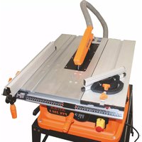
- Band saw BSV 315 (pre-assembled device unit)
- Saw band
- Saw table
Table insert -
Stopper guidance profile
-
Parallel stopper
- Pushstick
Fastener bag - Operating instructions
Assembly and operating instruction sheet
After unpacking, check the contents of the box for
completeness
possible transport damage.
Report any damage or missing items to your dealer, supplier or the manufacturer immediately. Complaints made at a later date will not be acknowledged.
Characteristic noise values
DIN EN ISO 3744
Application of the machine as band saw with standard saw band.
| Sound power level | Sound pressure level at the workplace | |
| No-load | LWA=80.8 dB(A) | LpA=70.1 dB(A) |
| Load | LWA=100.7 dB(A) | LpA=89.3 dB(A) |
Measuring uncertainty K: 3 dB(A)
The values given are emission values and must therefore not simultaneously represent safe workplace values too. Although there is a relationship between emission and immission levels, it can be reliably deduced whether additional precautionary measures are necessary or not. Factors, which can influence the immission level currently existing at the workplace include the duration of the effects, the special type of the workroom, other noise sources, etc. e.g. the number of machines and other adjacent processes. The permissible workplace values can also vary from country to country. This information should however enable an improved assessment of the danger and risk to be carried out.
Symbols on the machine
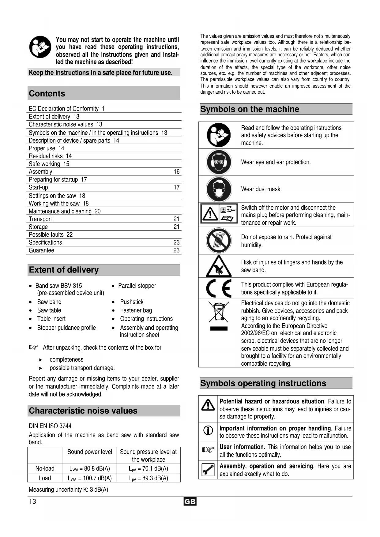
Read and follow the operating instructions and safety advices before starting up the machine.

Wear eye and ear protection.

Wear dust mask.
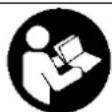
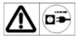
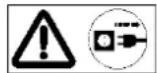
Switch off the motor and disconnect the mains plug before performing cleaning, maintenance or repair work.
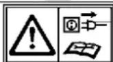
Do not expose to rain. Protect against humidity.
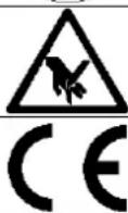
Risk of injuries of fingers and hands by the saw band.
This product complies with European regulations specifically applicable to it.
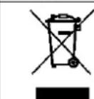
Electrical devices do not go into the domestic rubbish. Give devices, accessories and packaging to an ecofriendly recycling. According to the European Directive 2002/96/EC on electrical and electronic scrap, electrical devices that are no longer serviceable must be separately collected and brought to a facility for an environmentally compatible recycling.
Symbols operating instructions
| Δ | Potential hazard or hazardous situation. Failure to observe these instructions may lead to injuries or cause damage to property. |
| i | Important information on proper handling. Failure to observe these instructions may lead to malfunction. |
| User information. This information helps you to use all the functions optimally. | |
| Assembly, operation and servicing. Here you are explained exactly what to do. |
| 1 2 3 ... | Please refer to the attached assembly and operating instruction sheet for references to figure numbers in the text. | REV 3/4 | ATTACK |
Description of device / spare parts
1
| Pos. no. | Designation Order | number |
| 1 | Adjusting wheel for clamping of saw band | 362665 |
| 2 | Upper case door | |
| 3 | Pushing stick holder | |
| 4 | Pushing stick | 362872 |
| 5 | Circuit closer/breaker | 362658 |
| 6 | Lower saw band coping | |
| 7 | Lower case door | |
| 8 | Base frame | |
| 9 | Belt gear | |
| 10 | Lower band saw roll 362673 | |
| 11 | Crank for adjusting of belt tension | |
| 12 | Table insert | 362697 |
| 13 | Saw table | |
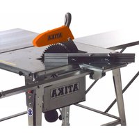
| 14 | Parallel stopper | 362698 |
| 15 | Saw band | 362662 |
| 16 | Upper band guidance | |
| 17 | Upper band saw roll 362672 | |
| 18 | Adjusting wheel for saw band coping | 362665 |
| 19 | Upper saw band coping | |
| 20 | Transverse adjustment saw table | |
| 21 | Splinters suction socket | |
| 22 | Base | |
| 23 | Line cord | |
| 24 | Motor | |
| 25 | Adjusting wheel for upper band saw roll | |
| 26 | Stopper guidance profile 362699 |
Proper use
- The device is suitable for cutting wood, wood like materials and plastics.
- Round materials (logs, pipes, etc.) are not permitted to be cut without a special device for this purpose.
- When endwise sawing plain work pieces a suitable stop angle must be used for a safe guidance.
- Only materials that can be safely placed are allowed to be cut.
- The intended usage also includes compliance with the operating, servicing and repair conditions prescribed by the manufacturer and following the safety instructions included in the instructions.
- Follow the relevant accident prevention rules for operation and other generally recognised health and safety at work rules.
- Any other use is deemed not to be use as prescribed. The manufacturer is not liable for any type of damage resulting from this: the user bears the sole risk.
- Unauthorised modifications on the device exclude a liability of the manufacturer for damages of any kind resulting from it.
- Only persons who are familiarised with the device and informed about possible risks are allowed to prepare, operate and service this device. Repair works may only be carried out by us or by a customer service agent nominated by us.
- This machine must not be used in an explosive environment or exposed to rain.
Metallic parts (wires etc.) have unconditionally to be removed from the material to be cut.
Residual risks
Even if used properly, residual risks can exist even if the relevant safety regulations are complied with due to the design determined by the intended purpose.
Residual risks can be minimised if the "Safety advices" and the "Intended usage" as well as the whole of the operating instructions are observed.
Observing these instructions, and taking proper care, will reduce the risk of personal injury or damage to the equipment.
- Risk of injury to fingers and hands by the tool (saw band) or work piece, e.g. during saw band replacement.
Injury by catapulted workpiece parts. - Throwback of the workpiece or workpiece parts.
- Breakage and expulsion of saw band.
- Risk from electricity when using improper electrical connections.
- Touching live parts of opened electrical components.
- Impairment of hearing when working on the machine for longer periods of time without ear protection.
- Emission of harmful wood dust when working without shavings exhaustor.
In addition, in spite of all the precautionary measures taken, non-obvious residual risks can still exist.
Safe working
Woodworking machines can be dangerous if not used properly. If electrical tools are used, the fundamental safety precautions must be met to preclude the risks of fire, electric shock and injuries to persons.
Before starting this device, read and keep to the following advice. Also observe the preventive regulations of your professional association and the safety provisions applicable in the respective country, in order to protect yourself and others from possible injury.
Pass the safety instructions on to all persons who work with the machine.
Keep these safety instructions in a safe place.
- Make yourself familiar with the equipment before using it, by reading and understanding the operating instructions.
- Be attentive. Be careful what you do. Behave sensibly when working. Do not use a power tool while you are tired or under the influence of drugs, alcohol or medication. A moment of inattention while operating power tools may result in serious personal injury.
- Do not overreach. Provide a safe standing position and keep at any time the balance.
-
Wear suitable work clothes:
-
Do not wear loose-fitting clothes or jewellery, they could be caught by movable parts.
-
- slip-proof shoes
Hairnet in case of long hair
- slip-proof shoes
-
Wear personal protective equipment:
-
Ear protection (the noise level on the workplace may exceed 85 dB (A))
Safety goggles
Dust mask with work activities generating dust -
Only operate the band saw on a
-firm
level
slip-free
- vibration free surface
- Keep your workplace in an orderly condition! Untidiness can result in accidents.
-
Provide a safe standing position and keep at any time the balance. Do not lean forward.
Take environmental influences into consideration: -
Do not expose the machine to rain.
- Do not use the machine in humid or wet environment.
- Provide for good illumination.
- Do not use this machine near inflammable liquids or gases.
-
The wood dust generated during operation impedes the necessary view and is harmful to health to some degree. Unless the machine is used outdoors, it must be connected to a chip exhaust system (e.g. portable dust remover).
-
Never leave the machine unattended.
-
Persons under the age of 18 must not operate the band saw. An exception is youngsters under the age of 16 within the scope of their vocational training under supervision.
- Keep other persons away.
Do not allow other persons, especially children, to touch the tool or cable.
Keep them away from your working area.
- Take the correct working position. The saw teeth must show to the operator.
- Only begin cutting after the saw band has reached its required rotational speed.
- Do not force the power tool. You work better and safer in the given performance range.
- Only operate the machine with complete and correctly attached safety equipment and do not alter anything on the machine that could impair the safety.
- Do not use any cracked saw bands or such that have changed their shape.
- Use only sharp saw bands since dull saw bands not only increase the danger of back kicking but also cause excessive load on the motor.
- Do use only saw bands according to ISO 3295 / DIN 8806-1.
The use of other tools and other accessories may present a risk of injury to you.
- Do not use the saw for purposes it is not intended for (see proper use).
- When longitudinally cutting narrow workpieces (distance between the saw blade and the parallel rip fence less than 120mm ), use the pushstick. (see "working instructions").
- To push narrow workpieces against the parallel rip fence, use a push block.
Push blocks can be purchased in retail outlets.
- Do not use defective pushsticks and blocks.
See to it that the pieces cut off are not caught and thrown away by the saw band. - Do not remove the splints, splinters and wastes with the hand out of the danger zone of the saw band.
- Cutting round timber is not allowed with the standard feeding assistance. When cutting round timber use a special device which safes the work piece from skewing.
-
Switch the machine off and remove the mains plug from the socket when
-
carrying out repair works
- maintenance and cleaning
- carrying out servicing and repair works, removal of faults (this also includes removing clamped splinters)
- checks of connecting lines, whether these are knotted or damaged
- transporting the saw
-saw band exchange -
leaving the saw unattended (even during short interruptions)
-
Maintain your machine with care:
-
Keep your tools sharp and clean in order to be able to work better and safer.
-
Follow the maintenance instructions and the instructions for tool exchange.
-
Keep the handles dry and free of oil and grease.
-
Check the machine for possible damage:
Before further use of the machine the safety devices and any parts that show minor damages must be checked carefully for their proper and intended function.
- Check whether movable parts function perfectly and do not stick or whether parts are damaged. All parts must be correctly installed and fulfil all conditions to ensure perfect operation of the machine.
- Damaged safety devices and parts must be properly repaired or exchanged by a recognized, specialist workshop; insofar as nothing else is stated in the instructions for use.
- Damaged or illegible safety labels have to be replaced.
- Do not allow any tool key to be plugged in!
Before switching on, check always that wrenches and adjusting tools are removed. - Store unused equipment in a dry, locked place out of the reach of children.
Electrical safety
- Design of the connection cable according to IEC 60245 (H 07 RN-F) with a core cross-section of at least
1.5 mm² for cable lengths up to 25 m
- 2.5mm^2 for cable lengths over 25m
- Long and thin connection lines result in a voltage drop. The motor does not reach any longer its maximal power; the function of the device is reduced.
- Protect yourself against electric shocks. Avoid body contact with grounded parts (e.g. pipes, heating apparatus, cookers, fridges etc.).
- Do not use the cable for purposes for which it is not meant. Protect the cable against heat, oil and sharp edges. Do not use the cable to pull the plug from the socket.
- Check regularly the cable of the saw and get possible damages repaired by an accepted specialist.
- When running the connection line observe that it does not interfere, is not squeezed, bended and the plug connection does not get wet.
- Regularly check the extension cables and replace them if they are damaged.
- Do not use any defective connection cables.
- When working outdoors, only use extension cables especially approved and appropriately labelled for outdoor use.
- Do not set up any provisional electrical connections.
- Never bypass protective devices or deactivate them.
- Only hook up the machine by means of a fault-current circuit breaker (30 mA).
The electrical connection or repairs to electrical parts of the machine must be carried out by a certified electrician or one of our customer service points. Local regulations - especially regarding protective measures - must be observed.
Repairs to other parts of the machine must be carried out by the manufacturer or one of his customer service points.
Use only original spare parts, accessories and special accessory parts. Accidents can arise for the user through the use of other spare parts. The manufacturer is not liable for any damage or injury resulting from such action.
Assembly
2
Assemble the base frame. Therefore, fasten the legs (A) with each time 8 screws M8 x 16, flat washers A 8,4 and screw nuts M8 at the frame (B).
3
Fasten the saw on the base frame.
4
Assemble the handle (11).
5
Replacing the saw band
Danger of cutting! Wear gloves when replacing the saw band.
- Open both case doors (2/7).
- Put upper saw band coping (19) completely down.
- Put upper band roll (17) down
turn the adjusting wheel (1) anti-clockwise, the saw band is relaxed
- Insert the saw band.
Pay attention to a correct position: the teeth must show forward (direction door).
- Put saw band centrally on the band roll (17).
- Turn adjusting wheel (1) clockwise until the saw band does not glide off any longer.
Before going on assembling carry out the following adjustments:
Clamp saw band (see „Saw band tension" p. 18)
Adjust saw band (see „Incline of the upper band saw roll" p. 18)
Adjust band guidances (see upper band guidance" and lower band guidance" p. 20)
7
Assemble saw table
Assemble the end stop screw (M6 x 35) at the bottom side of the saw table (13).
8
Guide saw table (13) over the saw band and put it on the saw table guidance (20).
9
Fasten saw table with 4 nuts (M8) and washers at the saw table guidance (20).
10
Adjust saw table
Angle the saw table (13) laterally.
Release the four fixation screws (C).
Angle saw table (13) in a way that the saw band is located in the centre of the table insert.
Refasten attachment screws (C).
11
Angle the saw table (13) rectangularly
Place upper saw band coping completely upwards (see "Adjustment of the upper saw band coping" p. 19)
Check saw band tension (see „Saw band tension" p. 18)
Release fixation screw (D).
Angle the saw table with the help of an angle rectangular to the saw band.
Refasten fixation screw (D).
12
Release the counter nut (E) and adjust the adjusting screw (F) until the adjusting screw touches the saw table. Refasten the counter nut.
13
Assemble parallel stopper
Assemble stopper guidance profile (26)
Push the stopper guidance profile (26) on the table top and fasten the wing screws.
14
You can assemble the parallel stopper (14) on the right or left side of the saw band.
Push the parallel stopper (14) on the stopper guidance profile (26) and fasten it like pictured.
15
Mount the holder (3) for the pushing stick.
Preparing for startup
To obtain a perfect working of the machine follow the following advices:
-
Place the saw in a place that fulfils the following conditions:
-
secured against slipping
- free of vibrations
- even
- free of tripping hazards
adequate light
Before each use, check
- Connection cables for defects (cracks, cuts, etc.)
Do not use any defective cables.
the table insert for its proper condition
the saw band for its faultless condition
- that all doors are closed
whether the pushstick is to hand
- Do not use any deformed or damaged saw bands.
- Replace a worn-out or damaged table insert immediately.
- When the machine is not used open-air it must be connected on both suction sockets with a splinter extraction system (i.e. portable small dust extractor).
Start-up
① Electric supply
Compare the voltage listed on the machine's type plate, e.g. 230V , with the mains voltage and connect the machine to a suited and and properly earthed electrical socket.
① AC-motor
Use an electrical socket with a rated voltage of 230V with a fault-current circuit breaker (30mA)
① Main fuse: 10 A slow
Use an connecting or extension cable in compliance with IEC 60245 (H 07 RN-F) having a core cross-section of at least:
1.5 mm² for cable lengths up to 25 m
2.5mm^2 for cable lengths over 25m
16
ON/OFF switch
Do not use any device where the switch can not be switched on and off. Damaged switches must be repaired or replaced immediately by the customer service.
Switching on
Press the green button (I) on switch.
① Restart protection in case of power failure
The device cuts off automatically in case of power failure. To restart, first push the red button (0) and then the green button (1).
Switching off
Press the red button (0) on switch.
Saw band selection
The saw band delivered by standard is suitable for wood and most plastics.
Consider when selecting the saw band,
that no edgeless or damaged saw bands are used.
that the selection of the saw band and the number of revolutions is suitable for the material to be cut.
Connect splinter extraction
In closed rooms work only with a splinter extraction (air speeds at suction socket of the saw ≥ 20m / sec
Sawing without splinter extraction only
for short-time service (up to 30 min.)
or with a protective mask
or open-air
If you do not connect splinter extractor sawdust will concentrate which you have to remove regularly.
Connect sawdust extraction system or small dust extractor with a suitable adapter to the sawdust suction socket.
Settings on the saw
17
Saw band tension
A too high stress can result in the break of the saw band. A too less stress can result in the drive wheel sliding through and then result in the stop of the saw band.
You can check the stress:
Put the upper saw band coping (19) completely upwards (see Adjustment of the upper saw coping) and press with the finger in the middle between the saw table and the upper saw coping transversally against the saw band
it shall only be possible to push the saw band in laterally by 3 - 5mm
18
With the adjusting wheel (1) the stress of the saw band can be corrected.
Increase stress (+)
turn adjusting wheel clockwise
Reduce stress (-)
turn the adjusting wheel anti-clockwise
19
Incline of the upper band saw roll
With the adjusting wheel (25) the incline of the upper band saw roll (17) can be changed. The adjusting causes that the saw band runs in the centre of the band saw roll.
Before adjusting release the fixation screw nut (G).
Saw band runs backwards
turn the adjusting wheel clockwise
Saw band runs forwards
turn the adjusting wheel anti-clockwise
After adjusting refasten the fixation screw nut (G).
20
Transverse adjustment of saw table
√
Release fixation screw (D).
The saw table can continuously be inclined against the saw band up to 45^ .
21
Parallel stopper
The parallel stopper (14) is clamped on the saw table. It can be assembled on the right or on the left of the saw band.
① Mount the stopper ruler on the side of the stopper guidance which faces towards the saw band.
22
Adjust cutting speed
- Open lower case door.
- Loosen drive belt by turning the crank (11) clockwise.
- Put drive belt on the corresponding belt pulley at the drive wheel (lower band saw roll) and on the corresponding engine belt pulley.
The adjustments are indicated in the following plan which is also fixed on the inside of the case door.
| Material | Cutting speed | |
| Hardwood Plastics NF-Metals | 370 m/min 1 | |
| Wood | 800 m/min | 2 |
Never put on the drive belt transversally. It must run either on both front or both back belt pulleys.
- Clamp again the drive belt by turning the crank (11) anticlockwise.
The drive belt shall be able to be bended in the middle app. 10mm
- Close lower case door.
- Keep saw running at least one minute for testing.
- Switch off the saw and pull out the power plug. Check then the position and the tension of the drive belt and correct it if necessary.
Working with the saw
Before starting to work consider the following safety advices to keep the risk of injuries as small as possible.
- Saw band o.k.?
- Parallel stopper ready to use?
-
Pushing stick ready to hand?
-
Upper and lower case door closed?
The case doors protect against touching the driven parts in the inside of the saw.
Workplace tidied?
- You may not start to operate the machine until you have read these operating instructions, observed all the instructions given and installed the machine as described!
Before changing or adjusting the saw (i.e. replacing saw band, inclining saw table, adjusting saw band coping etc.)
- Switch off device
- Wait for stop of the saw band
- Pull out power plug
Also, note the following important points:
- Wear protective clothing:
ear protection
- safety goggles
protective mask
- When sawing do not wear gloves, large clothes or jewels. Danger of entering!
Take the correct working position. The saw teeth must face the operator.
Take a position outside the danger zone of the saw band. - Never put into operation the machine when the doors protecting the saw band are open.
- Put the hands plain with closed fingers on the work piece.
- Saw only one work piece simultaneously. Never saw several work pieces or individual items combined as packs simultaneously. There is the risk that individual items can be caught uncontrolled by the saw band.
- Do not saw work pieces where cords, strings, bands, cables or wires are fixed. Danger of entering!
- Press the work piece when sawing on the saw table.
Pay attention to that the work piece does not cant itself. - Do not slow down the saw band by lateral pressure.
Use a work piece support plate so that when sawing long work pieces these will not fall from the table after cutting them through. - Never remove loose splinters, chips, or similar by hand.
At any case pay attention to all security advices.
Pushing stick
The pushing stick serves as enlargement of the hand and protects against accidental touching of the saw band.
-
When do you have to use the pushing stick?
-
When the distance between saw band and parallel stopper is less than 120mm
In case of straight cuts against the parallel stopper.
Hang in the pushing stick in case of non-use in the mounting on the side of the device.
Do not use the pushing stick when it is damaged and replace the pushing stick immediately.
23
Adjusting the upper saw band coping
The upper saw band coping protects against accidental touching of the saw band and flying sawdust.
The height of the upper saw band coping must be adjusted:
Before sawing, to adapt to the work piece height
- After changes of saw band (i.e. clamping or replacing saw band, adjusting saw table)
The distance between saw band coping and work piece must be 3mm that there is a sufficient protection against touching the saw band.
Adjusting:
- Release fixation screw (H).
- The required position of the saw band coping can be adjusted with the adjusting wheel (18).
- Refasten fixation screw (H).
Cutting round work pieces
Cutting round timber is not allowed with the standard feeding assistances. When cutting round timber use a special device which safes the work piece from skewing.
Edgewise cutting of plain work pieces
When sawing edgewise plain work pieces a suitable stop angle for a safe guidance must be used.
Cutting narrow workpieces
Width less than 120mm
Push the work piece with both hands forwards, within the saw band zone use the pushing stick.
Cutting wide workpieces
With the flat of the hand and the fingers closed, push the work piece to be cut along the stop.
Cutting long workpieces
Secure long workpieces against dropping down when finishing the cutting process. Use roller supports or similar devices for this purpose.
24
The sawing process
- Select and adjust parallel stopper (14) and saw table incline corresponding to the cutting type.
- Select and adjust speed of saw band according to the material.
When sawing with parallel stopper and inclined saw table the work piece can cant. The parallel stopper must therefore be fixed on the downwards inclined side of the saw table.
- Adjust distance between saw band coping and work piece to 3mm
- Put work piece on the saw table.
- Put in power plug.
- Switch on saw.
- Saw through work piece in one work step.
Hint:
Make always a test cut to be able to correct the adjustment.
- Switch off saw when it is not intended to go on sawing.
Maintenance and cleaning
Before each maintenance and cleaning work
- switch off device
- wait for stop of saw
- pull out power plug
Further maintenance and cleaning works than described in this chapter shall only be carried out by the manufacturer or companies named by the manufacturer.
For maintaining and cleaning, removed security devices must unconditionally be mounted properly and proved again.
Use only original parts. Other parts can result in unexpected damages and injuries.
Cleaning
Observe the following to maintain the functionality of the saw.
- Do not wash down device with water.
- Remove splints and sawdust only with a brush or vacuum cleaner.
Clean and oil all moving parts regularly.
Never use any grease!
Use for instance sewing machine oil, liquid hydraulic fluid or environmentally acceptable spray oil.
- Provide that the saw band stays rust-free and resin-free.
- Remove all resin residues from the saw bench top.
Resin residues can be removed with a commercial maintenance and care spray.
- Treat the surface of the saw table after cleaning with an anti-blocking agent.
- The saw band is a wearing part and becomes edgeless after longer or more frequent use respectively.
Renew then the saw band.
Maintenance
Saw band exchange

Danger of cutting! Wear gloves when replacing the saw band.

Only use suitable saw bands.
25 26
- Open both case doors (2/7).
- Release the 2 release handles (I) at the bottom side of the guidance profile (26).
- Take off the guidance profile (26).
27
- Put upper saw band coping (19) completely down.
- Put upper band roll (17) down.
turn the adjusting wheel (1) anti-clockwise, the saw band is relaxed
- Take out saw band.
- Put in new saw band.
① Pay attention to a correct position: the teeth must show forward (direction door).
- Put saw band centrally on the band roll (17).
- Turn adjusting wheel (1) clockwise until the saw band does not glide off any longer.
-
Fasten guidance gib and close lower case door.
-
Subsequently:
Clamp saw band (Saw band tension p. 18)
Adjust saw band (.,Incline of the upper band saw roll" p. 18)
Adjust band guidances (upper band guidance and lower band guidance p. 20)
Keep saw running at least one minute for testing
Switch off saw, pull out power plug and recheck adjustments

Adjusting upper band guidance
The upper band guidance consists of:
two guidance rolls (these guide the saw band laterally)
a support roller (this supports the saw band from behind)

Check the guidance rolls and the support roller after each saw band exchange and each saw band adjustment and readjust it if necessary.

Guidance rolls and support roller are wear parts. Check these regularly and replace the rolls in case of wear at the same time.
28
Adjust guidance rolls:
- Release screws (J).
- Adjust the holder (K) in that way, that the guidance rolls (L) start always app. 1 mm behind the teeth ground.
- Fasten screws (J).
29
- Release screws (M).
-
Press guidance rolls (L) against the saw band.
-
Open upper door and turn the band saw roll several times manually clockwise so that the guidance rolls set in the correct positions
both guidance rolls must abut slightly on the saw band.
- Refasten screws (M).
- Close upper case door.
30
Adjust support roller:
- Release locking lever (N).
- Press support roller (O) against saw band so that it abusts slightly on the saw band.
- Refasten locking lever (N)

Adjusting lower band guidance
The lower band guidance consists of:
two guide pins (these guide the saw band laterally)
a support roller (this supports the saw band from behind)

Readjust the guide pins and support roller after each saw band exchange and each saw band adjustment.

Guide pins and support roller are wearing parts. Check these regularly and replace the pins and roller in case of wear at the same time.
26
- Release the 2 release handle on the bottom side of the guidance gib (26).
- Take off the guidance gib (26).
9
- Release the 4 nuts and washers on the saw table guidance (20) and take off the saw table (13).
31
Adjust guide pins:
- Release screws (P).
- Adjust the holder (Q) in a way that the guide pins (R) start app. 1 mm behind the teeth ground.
- Fasten screws (P).
- Press guide pins (R) against the saw band.
32
- Open upper door and turn band saw roll several times manually clockwise that the guide pins set in the correct position
both guide pins must abut slightly on the saw band. - Refasten screws (S).
- Close upper case door.
33
Adjust support roller:
- Release screw (T).
- Press support roller (U) against saw band so that it abusts slightly on the saw band.
- Refasten screw (T).
- Guide the table again over the saw band and screw it on at the saw table guidance.
- Refasten the stopper guidance profile (26).
Transport
Remove mains plug before each transport.
Transport the saw only with:
- the upper saw band guidance positioned completely downwards
- unscrewed jutting out accessories
Storage
Remove the mains plug from the socket.
-
Store unused equipment in a dry, locked place out of the reach of children.
To extend the service life of the saw and guarantee smooth operation, before storing for a longer period -
thoroughly clean the saw
treat all movable parts with an environmentally friendly oil
Never use any grease!
Before each fault clearance
Switch off device
Wait for stop of saw
- Pull out power plug
After each fault clearance, put into operation and recheck all security installations.
| Fault | Possible cause | |
| Machine fails to start after switching on or switches off during idle running | • Power failure • Extension cable defect • Motor or switch defect | • Check safety fuse • Check cable, no longer use defect cable • Have motor or switch checked by an approved electrician or replaced by original spare parts |
| Motor hums, but does not initiate | • Condenser defect | • Condenser should be replaced by customer service |
| Machine stops while cutting | • Saw band edgeless • Feed too large | • Replace saw band • Allow the motor to cool off and then continue work using less pressure |
| Work piece jams when pushing forward or pulling backward | • Saw band edgeless • The parallel stopper is not parallel to the saw band | • Hold the work piece firmly and switch off the motor immediately. Then renew the saw band. • Readjust the parallel stopper. |
| Burn marks at the cut edges | • Saw band is not suitable for the work step or edgeless | • Replace saw band |
| Saw band breaks | • Wrong saw stressing • To high load • Wrong saw band | • Adjust saw band stress • Reduce pressure against the saw band. • Wrong saw band → thin work piece = small saw band → thick work piece = broad saw band |
| Saw band contorted | • To high lateral load | • Avoid lateral pressure on the saw band. |
| Saw band runs out of cutting line or passes of | • Saw band does not run centrally on the upper band saw roll | • Adjust incline of the upper band saw roll |
| Saw vibrates | • Insufficient fixation • Saw table loose • Fixation screws of motor lose | • Fix saw on suitable ground • Adjust and fix saw table • Fasten fixation screws |
| Sawdust exit blocked | • No extraction system connected • Extraction power to weak | • Switch off saw, remove sawdust and connect extraction system • Switch off saw, remove sawdust and increase extraction power (air speeds ≥ 20 m/sec on suction socket of sawdust. |
| Saw band does not move although motor is running | • Drive belt lose • Drive belt defect | • Clamp drive belt • Replace drive belt |
Technical data
| Type / Model BSV 315 | |
| Year of construction see last page | |
| Motor output P1 | 740 W |
| Mains voltage 230 V | |
| Mains frequency 50 Hz | |
| Idle speed 1400 min | -1 |
| Fuse protection 10 A slow | |
| Cutting speed 370 m/min. & 800 m/min. selectable | |
| Length of saw band 2240 mm -10 mm | |
| Width of saw band 12.5 ± 1 mm | |
| Thickness of saw band max. 0.5 mm -0.1 mm | |
| Saw band roll 315 mm | |
| Saw table size 400 x 520 mm | |
| Transverse adjustment saw table | 0 - 45° |
| Cutting height max. | 155 mm |
| Width of passageway max. | 300 mm |
| Exhaust connector | Ø 100 mm |
| Dimensions (length x width x height) | 600 x 760 x 1700 |
| Weight | 50.5 kg |
Commercial small dust removers or industrial vacuum cleaners can be used for exhaustion.
Guarantee
Please note the attached guarantee declaration.

Indkobling / Frakobling
Lossa arreteringsmuttern (G) fore justering.

Sagbandet Ioper bakat
Lossa arreteringsskruven (D).

- Scie à ruban
- EN61029-1:2009; EN61029-2-5:2002; EN55014-1:2006+A1; 61000-3-2:2006+A1+A2; EN61000-3-3:2008; EN55014-2:1997+A1+A2
- Contents
- Extent of delivery
- Characteristic noise values
- Symbols on the machine
- Symbols operating instructions
- Description of device / spare parts
- Proper use
- Residual risks
- Safe working
- Electrical safety
- Assembly
- 2
- 3
- 4
- 5
- Replacing the saw band
- 7
- Assemble saw table
- 8
- 9
- 10
- Adjust saw table
- 11
- 12
- 13
- Assemble parallel stopper
- 14
- 15
- Preparing for startup
- Start-up
- ① Electric supply
- ① Main fuse: 10 A slow
- 16
- ON/OFF switch
- Switching on
- Switching off
- Saw band selection
- Connect splinter extraction
- Settings on the saw
- Saw band tension
- You can check the stress:
- Incline of the upper band saw roll
- Saw band runs backwards
- Saw band runs forwards
- Transverse adjustment of saw table
- Parallel stopper
- Adjust cutting speed
- Working with the saw
- Pushing stick
- Adjusting the upper saw band coping
- Adjusting:
- Cutting round work pieces
- Edgewise cutting of plain work pieces
- Cutting narrow workpieces
- Cutting wide workpieces
- Cutting long workpieces
- The sawing process
- Maintenance and cleaning
- Before each maintenance and cleaning work
- Cleaning
- Maintenance
- Saw band exchange
- 26
- 27
- Adjusting upper band guidance
- 28
- Adjust guidance rolls:
- 29
- 30
- Adjust support roller:
- Adjusting lower band guidance
- 26
- 31
- Adjust guide pins:
- 32
- 33
- Transport
- Storage
- Before each fault clearance
- Technical data
- Guarantee
- Indkobling / Frakobling
Brand : ATIKA
Model : BSV 315
Category : Saw