Cabinet Hardware Jig - Drill Kreg - Free user manual and instructions
Find the device manual for free Cabinet Hardware Jig Kreg in PDF.
User questions about Cabinet Hardware Jig Kreg
0 question about this device. Answer the ones you know or ask your own.
Ask a new question about this device
Download the instructions for your Drill in PDF format for free! Find your manual Cabinet Hardware Jig - Kreg and take your electronic device back in hand. On this page are published all the documents necessary for the use of your device. Cabinet Hardware Jig by Kreg.
USER MANUAL Cabinet Hardware Jig Kreg
Cabinet Hardware Jig
Owner's Manual | Benutzerhandbuch | Guide d'utilisation | Manual del propietario | Brugervejledning | Omistajan käytöopas | Manuale di istruzioni | Gebruikershandleiding | Brukerveiledning | Instrukcja uzytkownika | Manual do Utilizador | Рожовскво польбователя | Ägarhandbok
1
Safety
Follow your drill manufacturer's instructions and safety guidelines.
Always wear eye protection.
Clamp the jig to the workpiece. Do not hold it in place by hand.
Keep your body and hands away from sharp bit edges and moving parts.
Keeps hands and fingers away from the back face of the workpiece when drilling.
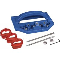
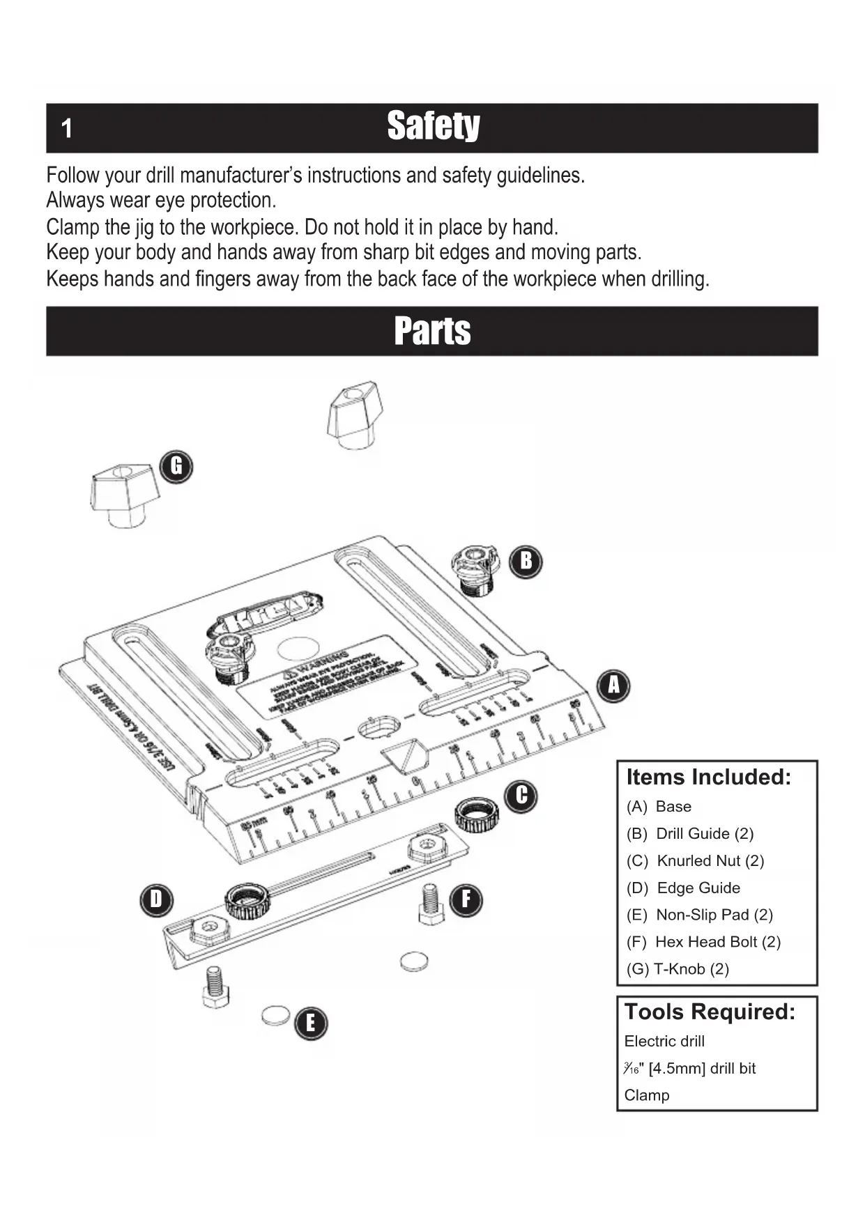
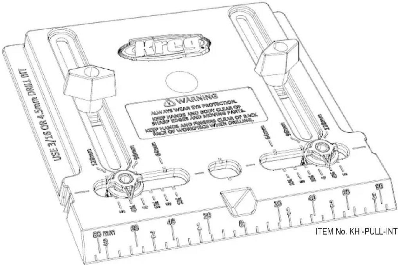
Parts
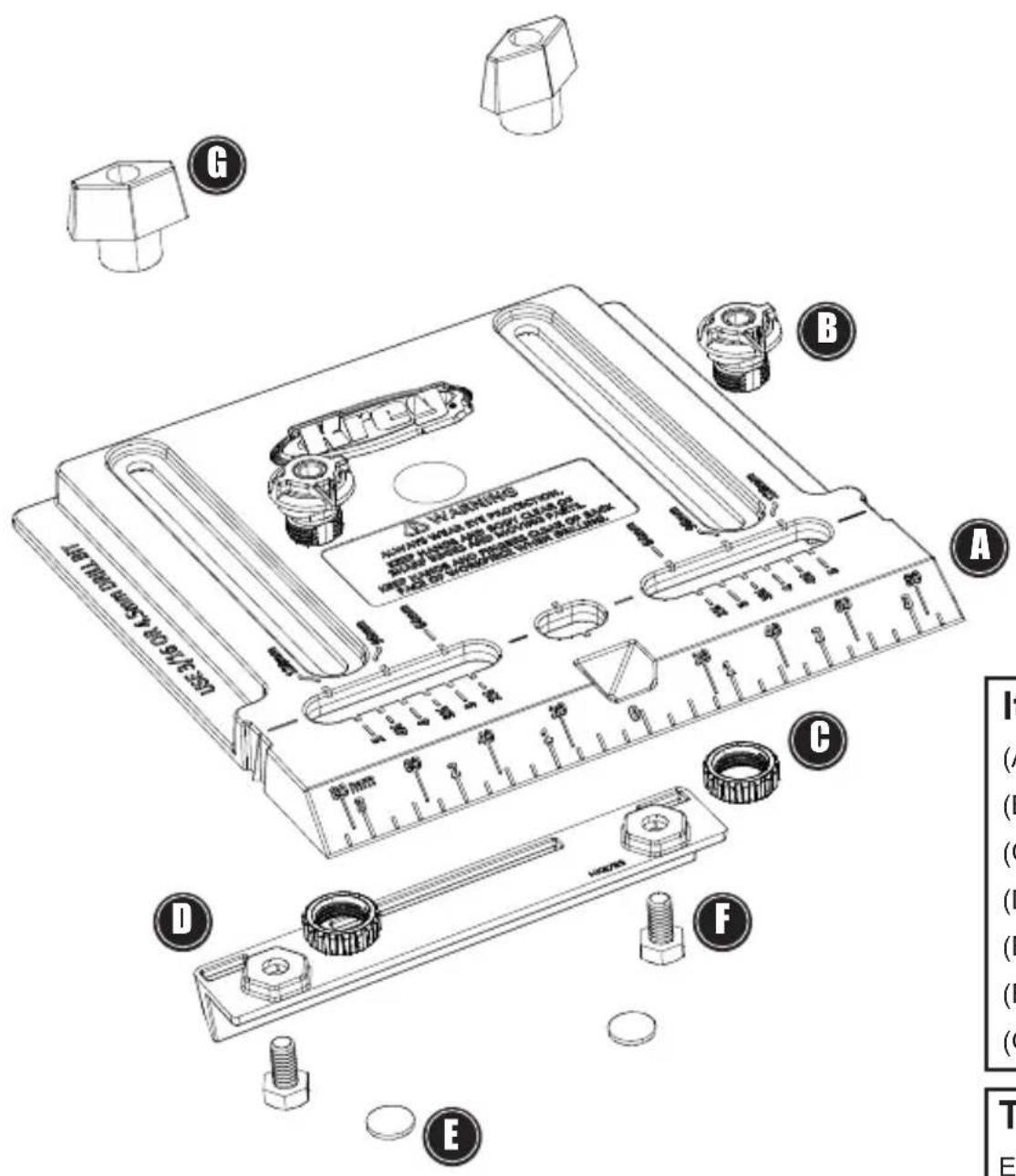
Items Included:
(A) Base
(B) Drill Guide (2)
(C) Knurled Nut (2)
(D) Edge Guide
(E) Non-Slip Pad (2)
(F) Hex Head Bolt (2)
(G) T-Knob (2)
Tools Required:
Electric drill
%_16 [4.5mm] drill bit
Clamp
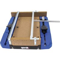
Assembly
2
Remove the Non-Slip Pads from the backing paper and apply them to the circular recesses in the Edge Guide. Position the Edge Guide between the inch scales on the bottom of the Base. Insert the Hex Head Bolts into the holes in the bottoms of the hexagonal recesses and thread on the T-Knobs from the top of the Base.
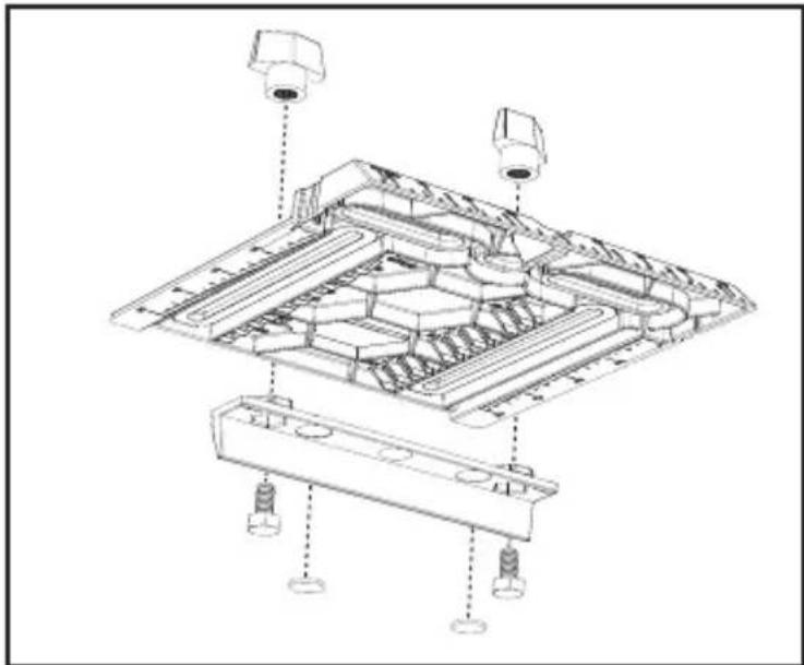
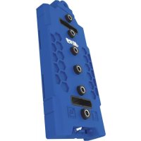
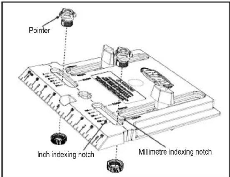
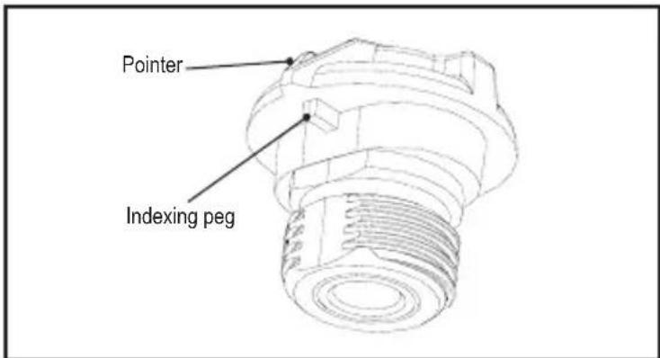
For Pulls: Insert the Drill Guides into the slots on both sides of the centre hole, aligning the pointer on each Drill Guide with the dimension on the Base that matches the centre-to-centre dimension of your pull. The Base features centre-to-centre dimensions for common inch and metric pulls. Make sure the indexing peg under the pointer on the bottom face of the Drill Guide is seated in the correct indexing notch in the Base. Thread Knurled Nuts onto the Drill Guides from the bottom of the Base.
Assembly
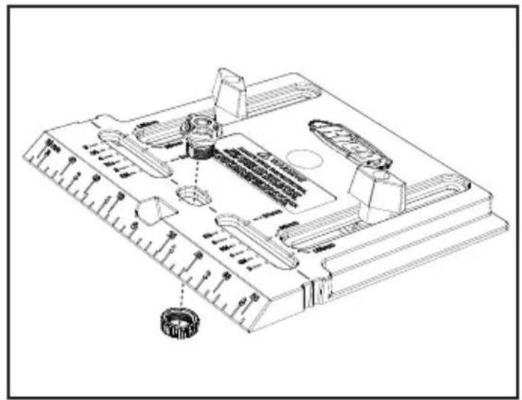
For Knobs: Insert one Drill Guide in the centre hole and thread on a Knurled Nut from the bottom of the Base.
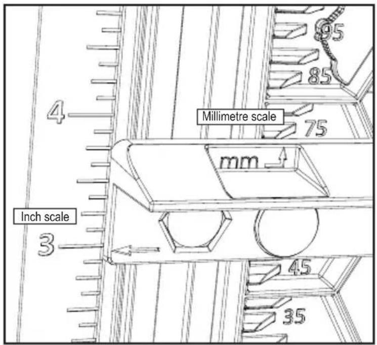
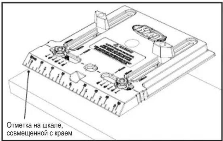
Adjust the Edge Guide to the desired distance from the edge of the workpiece on which you wish to mount the pull or knob. For dimensions in inches, align the arrows at the ends of the Edge Guide with the appropriate dimension on the inch scales along the edges of the Base. For dimensions in millimetres, align the back edge of the Edge Guide with the appropriate dimension on the millimetre scales along the inside edges of the Edge Guide adjustment slots. Tighten the T-Knobs.
ATTENTION The Edge Guide adjusts to centre the Drill Guide(s) from 1" to 5" [25mm to 120mm on the metric scale] from the edge of the workpiece.
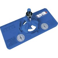
Using the Jig
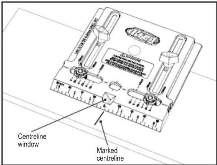
Mark a centreline for the pull or knob on the workpiece. Chuck a 3 / 16 " [4.5mm] drill bit into your drill. Position the Cabinet Hardware Jig with the Edge Guide against the edge of the workpiece and the marked centreline in the Centreline Window. Clamp the Jig to the workpiece, insert the drill bit into the Drill Guide(s) and drill the hole(s). Example shows the jig set up for a pull.
WARNING Whenever possible, clamp the Cabinet Hardware Jig to the workpiece. If you must hold the Jig in place with your hand, keep hands and fingers away from the back face of the workpiece when drilling.
ATTENTION To prevent chip-out as the drill bit exits the workpiece, clamp a piece of scrapwood to the back of the workpiece.
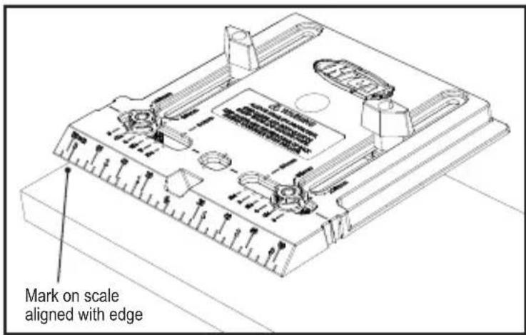
Additional Alignment Features: For centring a knob up to 312 [89mm] from the top or bottom edge of a door, use the inch or millimetre scales on the bevelled edge of the Base.
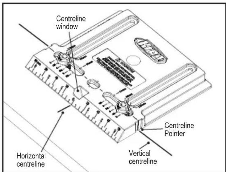
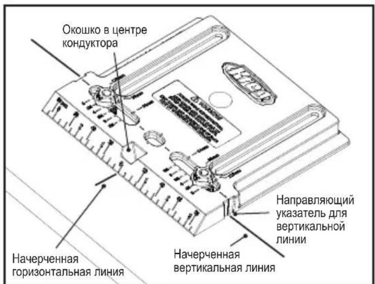
For aligning the Cabinet Hardware Jig at distances beyond the 5" [127mm] capacity of the Edge Guide, mark horizontal and vertical centrelines on your workpiece, remove the Edge Guide, and align the Jig by using the Centreline Pointers at the edges of the Base and the Centreline Window.
1
Sicherheit
I PEPDUYPEXEHENE. Ipn BO3MOXHOCTN KpeHnTe KOHdyKTop Ha pa6ooyem obBeKeTc nOMOuBIO 3aXIMa.
EcnBam Heo6xOIMO depkaTb KOHyKTOp pyKo, CneIte 3a Tem, YTO6bl Baun pyKn n PJIbCbl He HaxOINNCB B MeCTe CBePHeHnC DpyRcSTOpOHb pa6OeRo O6bEkTa.
BHIMAHNE. YTo6bI npEoTbpaTnTb
BbIKpaUHBAHHe B MOMeHTe N3BLeueHnCBePna n3 pa6oJero o6BJeKTA, npKpeNte KycOK DoCKn C 3aDHei CTOpOHbI pa6oJero o6BJeKTA.
DOnoJIHHTeJIbHbIe BO3MOXHOCTN
BbipabHbHaHa:ДЯБырabHbHaHa
no ueHtpy kpyrIoi pyuKn do 31 / 2" [89 MM] OT BepxHero nnn HnKHeRo KpaanBepn, nCNoIb3yIte uKaany B dIOImax nnn MmJIIMMeTpax Ha cKOUeHHoN KpOMKe KOHdYKTopa.
YTO6bI paCNOJoxnTb KOHyKTOp dJa
yCTaHOBKn pyueK Ha paCCTOraHnn 6OJIbWeM,
YeM dINHa HAnpaBnaIOuSei NO KpaIO (5" [127 MM]), Ha BaWem pa6ooyem obBeKeTe
HaueptNTe rOpN3OHTaJIbHyU IO BepTKaJIbHyU
IIHNn, CHIMITE HAnpaBnaIOuSyU IO KpaIO
N BbIPOBHnTE KOHyKTOp, NcNoJIb3yJ
Ha npBaBnHOUsn yKa3aTeNb dJa BepTKaJIbHOJ
IIHNn Ha KOHyKTOpE i OKoUko B cEHTrpe
KOHyKTopa.
1
Sakerhet
For assistance with any Kreg product, contact us through our Web site or call Customer Service.