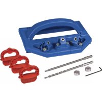
Shelf Pin Jig - Drill Kreg - Free user manual and instructions
Find the device manual for free Shelf Pin Jig Kreg in PDF.

User questions about Shelf Pin Jig Kreg
0 question about this device. Answer the ones you know or ask your own.
Ask a new question about this device
Download the instructions for your Drill in PDF format for free! Find your manual Shelf Pin Jig - Kreg and take your electronic device back in hand. On this page are published all the documents necessary for the use of your device. Shelf Pin Jig by Kreg.
USER MANUAL Shelf Pin Jig Kreg
Manual applies to Item # KMA3225, KMA3232, and KMA3232-INT
natural_image
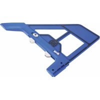
Technical line drawing of a mechanical housing component with hexagonal cutouts and mounting holes (no text or symbols)WARNING Every user must read and follow instructions and safety precautions in this manual. Failure to do so could result in serious injury. Save manual for future reference.
We're here to help.
We want you to have an exceptional project building experience. If you have questions or need support, please get in touch. 1-800-447-8638 | technicalsupport@kregtool.com
Tell us about your experience.
Your opinion counts. And we're always looking for ways to improve. Share your feedback so we can keep growing and innovating for you. www.kregtool.com/feedback
| English | 2 |
| French (N. America) | 13 |
| Spanish (N. America) | 25 |
| French | 37 |
| Spanish | 49 |
| German | 61 |
Table of Contents
Safety Precautions ..... 2
Pre-Assembly....3
Assembly 4
Face-Framed Cabinets ..... 5
Frameless Cabinets 6
Operation 8
Using the Jig for Cabinet Hardware Installation 9
Connect Jigs Together ..... 11
Maintenance .....11
Care and Cleaning .....11
Troubleshooting .....11
Accessories. . . . . . . . . . . . . . . . . . . . 11
Safety Precautions
WARNING Before using a power tool with this product, read, and follow the tool manufacturer's instructions and safety precautions in addition to the safety precautions below to reduce risk of serious injury from hazards such as fire, electric shock, or rotating drill bit.
- Follow your drill manufacturer’s safety guidelines.
- Follow your clamp manufacturer's safety guidelines. Keep your hands clear when clamping to avoid pinch points. The clamping limit on this jig is 300 lbs.
■ When drilling, always ensure that the workpiece is clamped securely. It is dangerous to hold the workpiece in place by hand.
■ The drill bit is sharp; handle with care and avoid unintended cutting. The drill bit may be hot after repetitive use.
■ Always wear personal protective equipment certified as adequate in addition to what your drill manufacturer requires.
■ Do not allow familiarity gained from frequent use of your tools to replace safe work practices. A moment of carelessness is sufficient to cause severe injury.
WARNING Avoid awkward hand positions where a sudden slip could cause contact with the rotating drill bit.
WARNING Do not operate this tool or any machinery while under the influence of drugs, alcohol, or medications.
WARNING This product can expose you to chemicals including Acrylonitrile and other chemicals, which are known to the State of California to cause cancer and reproductive harm. For more information go to www.P65Warnings.ca.gov.
WARNING Drilling, sawing, sanding, or machining wood products can expose you to wood dust, a substance known to the State of California to cause cancer. Avoid inhaling wood dust or use a dust mask or other safeguards for personal protection. For more information go to www.P65Warnings.ca.gov/wood.
Pre-Assembly
Review this section before you begin. Ensure you have all tools/materials on hand and compare the package with the items listed in the Product Description section. If any item appears missing or lost, do not use this product. Contact Technical Support or return product to place of purchase.
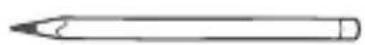
Recommended Tools/Materials
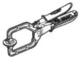
natural_image
Line drawing of a pliers tool (no text or symbols)Clamp Pencil

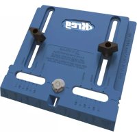
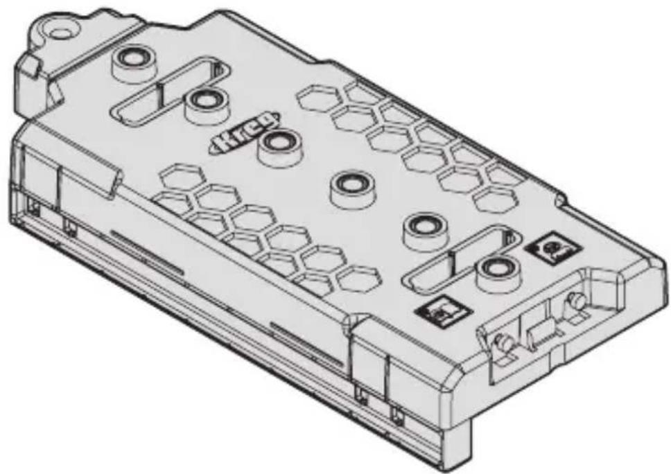
Product Description
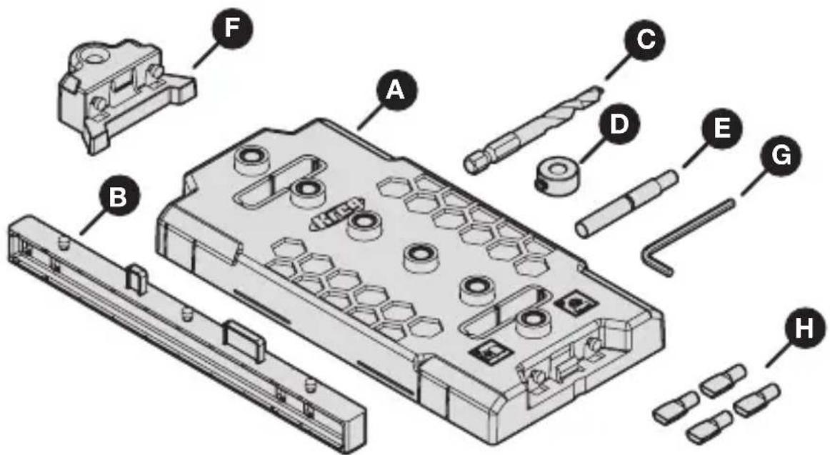
text_image
Exploded view diagram of a mechanical assembly with labeled parts A through H| Part Description Part Description |
| A Shelf Pin Jig E** Indexing pin |
| B Fence F Jig extension |
| C* Drill bit G Hex wrench |
| D Stop collar with set screw H 1/4" |
| mm Shelf pins (4x) | |
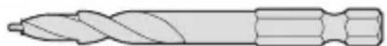
*If replacement or different size drill bits are needed, 1/4" or 5 mm drill bits are available separately.
**The indexing pin is double ended for both 1/4" and 5 mm shelf pin holes.
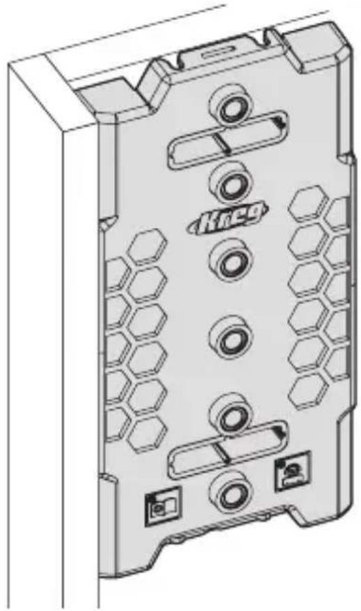
Onboard Tool Storage
The jig (A) provides onboard storage for these items:
■ Hex wrench (G)
■ Indexing pin (E)
■ Drill bit (C) with stop collar (D) attached
text_image
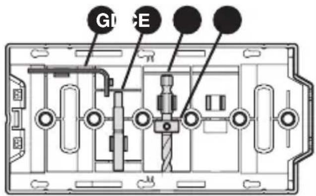
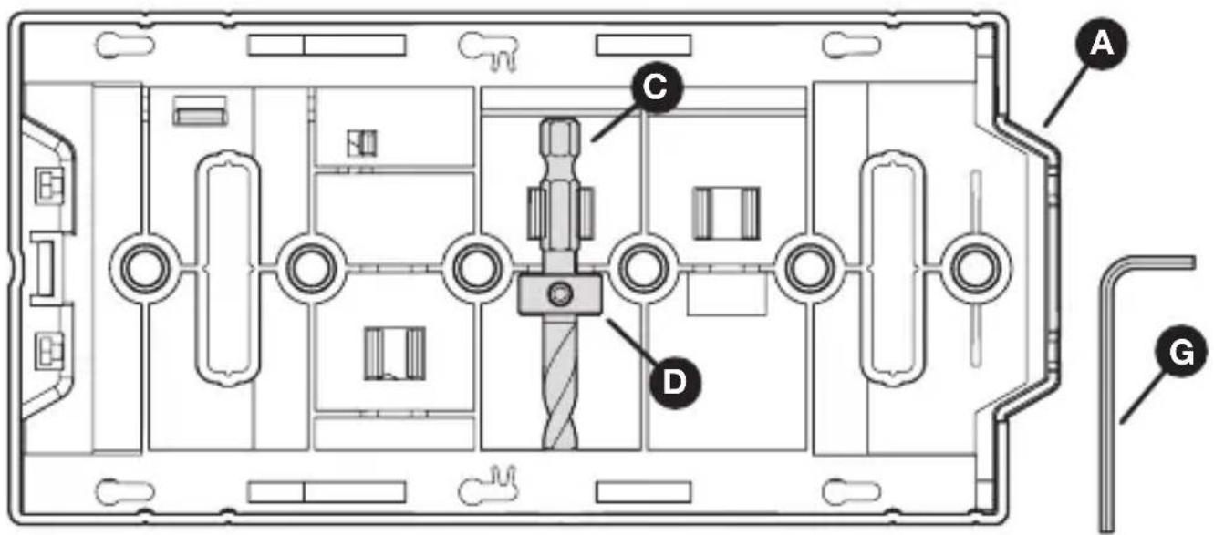
G1 EAssembly
1 Set the Stop Collar on the Drill Bit
a. Slide the stop collar (D) onto the drill bit (C).
b. Place the drill bit (C) and stop collar (D) into the storage slot on the back of the jig (A).
c. Slide the end of the drill bit (C) into the hole on the edge of the storage slot until it stops.
d. Position the stop collar (D) into the recess of the storage slot.
e. Use the hex wrench (G) to tighten the set screw in the stop collar (D).
text_image
Technical diagram of a device interior with labeled components A, C, D, and G2 Identify Your Cabinet Type
For face-framed cabinets, continue to the next section.
For frameless cabinets, skip to Attach the Fence to the Jig (page 6).
natural_image
Pure geometric line drawing of a corner bracket without any text, numbers, or symbols
natural_image
Simple 3D line drawing of a corner bracket (no text or symbols)Face-Framed Cabinets
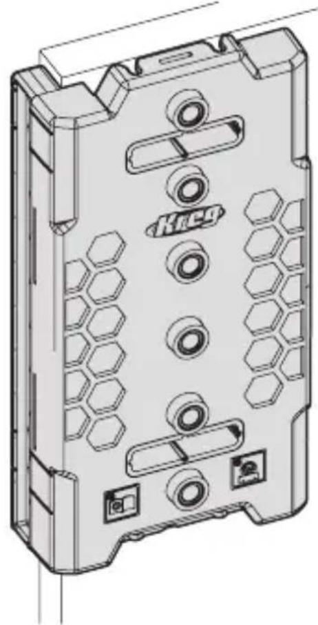
1 Position the Jig
Tip Although you can use either the top or bottom of the jig for reference, we recommend using the top so that you can use the jig extension as you move downward. Use the same reference end of the jig while drilling all shelf pin holes to maintain accurate left to right and front to back alignment.
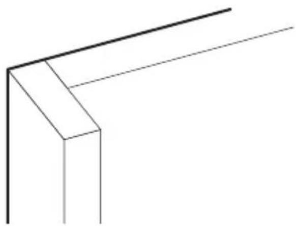
a. Align the jig with the inside corner of the cabinet and the face-frame.
natural_image
Technical line drawing of a mechanical housing component with hexagonal patterns and mounting holes (no text or symbols)2 Clamp the Jig
WARNING Follow your clamp manufacturer's safety guidelines. Keep your hands clear when clamping to avoid pinch points. The clamping limit on this jig is 300 lbs.
a. Use a clamp in the location shown below to secure the jig (A) in place. b. If using two connected jigs, clamp both.
Tip If your cabinet is already assembled, remove the fence and place the jig against the back of the cabinet using the same reference point as the front and carefully hold in place while you drill your first hole. Then use the jig extender and index pin to continue.
natural_image
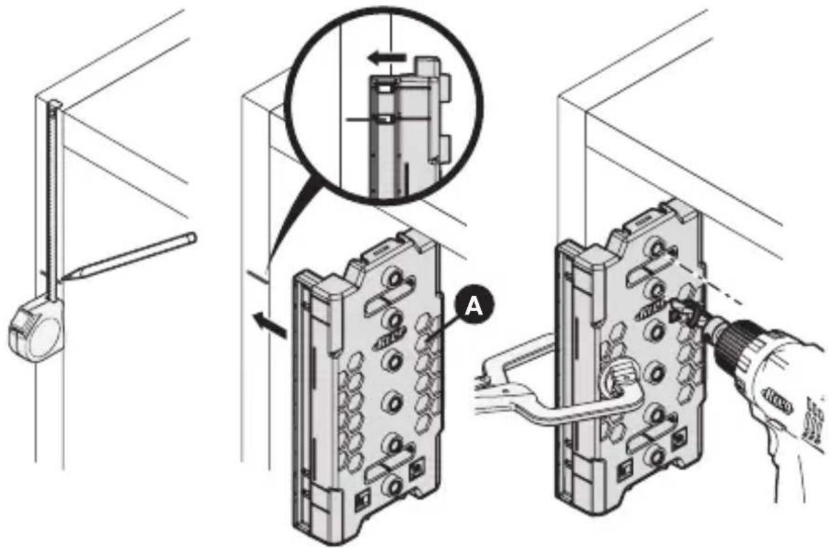
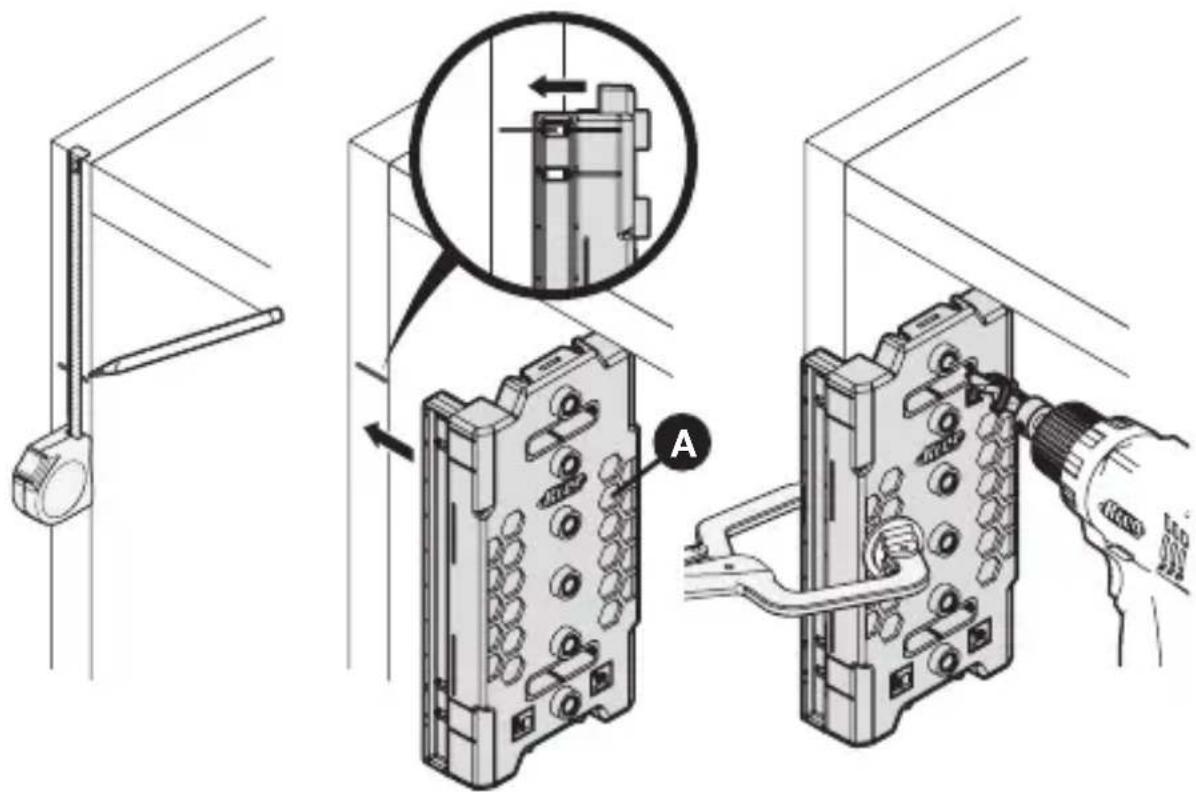
Technical line drawing of a computer tower with visible socket, connectors, and ventilation slots (no text or symbols)Frameless Cabinets
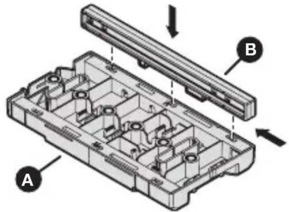
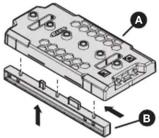
1 Attach the Fence to the Jig
a. Insert the fence (B) into the jig (A) base. b. Slide the fence (B) horizontally to secure it in place.
text_image
Technical diagram of a mechanical component with labeled parts A and B, showing internal structure and assembly.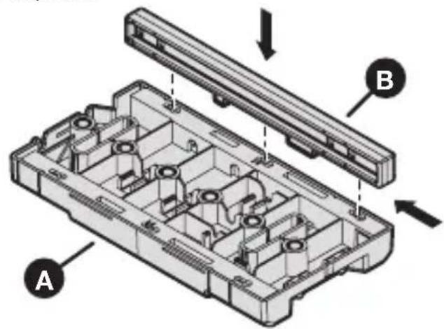
text_image
Technical diagram of a device housing with labeled components A and B, showing internal compartments and structural details.Note To remove the fence (B), slide the fence horizontally and pull away from the jig (A).
2 Position the Jig
Tip Although you can use either the top or bottom of the jig for reference, we recommend using the top so that you can use the jig extension as you move downward. Use the same reference end of the jig while drilling all shelf pin holes to maintain accurate left to right and front to back alignment.
Note When moving from the front to back holes, attach the fence to the other side of the jig.
a. Align the jig with the inside corner of the cabinet and the fence with the front of the cabinet.
natural_image
Technical line drawing of a mechanical housing component with hexagonal patterns and mounting holes (no text or symbols)3 Clamp the Jig
WARNING Follow your clamp manufacturer's safety guidelines. Keep your hands clear when clamping to avoid pinch points. The clamping limit on this jig is 300 lbs.
a. Use a clamp in the location shown below to secure the jig (A) in place.
b. If using two connected jigs, clamp both.
natural_image
Technical line drawing of a computer monitor with ports and cable (no text or symbols)Tip If your cabinet is already assembled, remove the fence and place the jig against the back of the cabinet using the same reference point as the front and carefully hold in place while you drill your first hole. Then use the jig extender and index pin to continue.
Operation
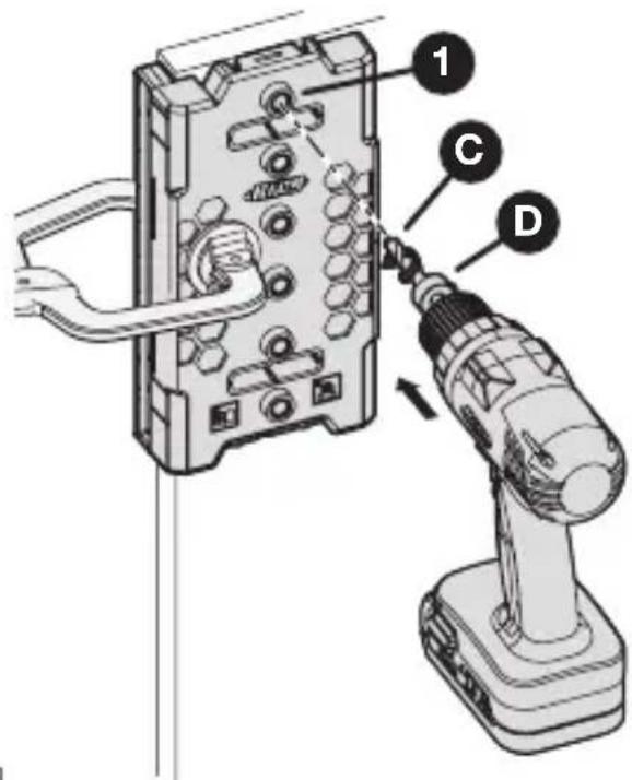
1 Drilling the Shelf Pin Holes
WARNING When drilling, always ensure that the workpiece is clamped securely. It is dangerous to hold the workpiece in place by hand. The drill bit is sharp; handle with care and avoid unintended cutting. The drill bit may be hot after repetitive use.
a. Place your prepared drill bit (C) with stop collar (D) into your drill.
b. Insert your drill bit (C) into the drill guide (1) and bring your drill up to speed before contacting the wood.
c. Drill until the stop collar (D) stops going any deeper due to contact with the drill guide.
d. Remove the drill bit (C) from the drill guide while the drill bit is still rotating.
text_image
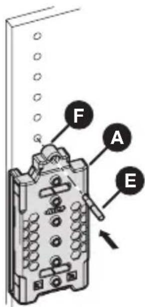
Diagram showing a drill bit being inserted into an electronic device, labeled with components 1, C, and D.2 Drilling an Extended Run of Shelf Pin Holes
Note The drill extension does not have a drill guide and should not be used for drilling.
a. Drill the first set of shelf pin holes.
b. Unclamp the jig (A).
c. Connect the jig extension (F) to the top of the jig (A).
d. Slide the jig (A) to align the jig extension (F) hole with the last shelf pin hole.
e. Insert the indexing pin (E) through the jig extension (F) and shelf pin hole to stabilize the jig (A).
f. Clamp the jig (A) in place.
g. Drill the next set of shelf pin holes.
Tip If you need to start your holes from the bottom, remove the jig extension (F) and use the indexing pin (E) in the drill guides and existing holes for alignment.
text_image
F A EUsing the Jig for Cabinet Hardware Installation
When building frameless cabinets, the jig can be used to correctly mount concealed hinge plates and first hole alignment for most drawer slides.
Note Check your hardware mounting instructions before drilling. The drill guide holes are 1.45" (37 mm) from the sides of the jig with 1.25" (32 mm) between holes.
Marking Concealed Hinge Mounting Holes
a. Mark the desired center line of the hinge on the cabinet.
b. Position the jig (A) using the position indicator window to align the center of the two drill guide holes.
c. Clamp the jig to the frameless cabinet.
Important To use the provided screws from the hinge manufacturer, only use the drill bit to mark the location of the screws.
d. If using a standard wood screw, bring your drill up to speed and lightly touch the cabinet to break the surface.
e. If using a 5 mm system screw, use the 5 mm drill bit to drill the hole.

text_image
Technical diagram showing installation of a device with labeled components and a magnified inset highlighting internal structure.Marking Drawer Slide Mounting Holes
a. Mark the desired center line of the drawer slide on the cabinet.
b. Position the jig (A) using the position indicator window to align the drill guide hole.
c. Clamp the jig to the frameless cabinet.
Important To use the provided screws from the slide manufacturer, only use the drill bit to mark the location of the screws.
d. If using a standard wood screw, bring your drill up to speed and lightly touch the cabinet to break the surface.
e. If using a 5 mm system screw, use the 5 mm drill bit to drill the hole.

f. Attach the slide with the first screw and level to attach the remaining screws.
text_image
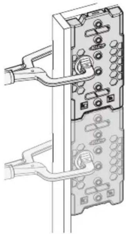
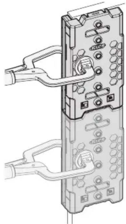
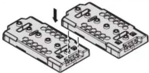
Technical diagram showing installation steps of a device with labeled components and a magnified inset viewConnect Jigs Together
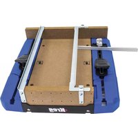
Connect two or more jigs together for longer drilling capability. Insert the top of the second jig into the extension connector at the bottom of the first jig.
natural_image
Technical illustration of two mechanical components with bolt holes and a downward arrow indicating assembly (no text or symbols)Maintenance
Keep all parts clean of dust and debris.
Replace the drill bit when it is dull.
Care and Cleaning
To clean, wipe with a clean rag or blow compressed air on all parts.
To store, place all parts and hardware into the storage positions on the back of the jig.
Troubleshooting
| Problem Possible Cause Solution | ||
| It is difficult to drill the hole. | The drill is in reverse. Check and reset the drill to forward. | |
| It is difficult to drill the hole. | The bit is dull. Replace the bit. | |
| There is excessive tear out on holes. | The bit is dull. Replace the bit. | |
| The jig is not clamped properly. | Check and clamp the jig properly. | |
| The drill bit is started while it is in contact with the wood. | Insert the drill bit into the drill guide and bring the drill up to speed before contacting the wood. | |
| The side to side alignment is off. | Not using the same reference end. | Use the same reference end for both sides of the cabinet. |
Accessories
KMA3210 1/4" Shelf Pin Jig Drill Bit KMA3215 5 mm Shelf Pin Jig Drill Bit

text_image
Kreg®EXPLORE. BUILD. SHARE.
We're makers just like you. That's why we love to see what you're working on. Share with the community and get inspired!
madewithKreg
Get free plans, project resources, and more. kregtool.com and buildsomething.com
GUIDE D'UTILISATEUR

text_image
Kreg®natural_image
Technical line drawing of a mechanical housing component with hexagonal cutouts and mounting holes (no text or symbols)natural_image
Line drawing of a pair of pliers (no text or symbols)Serre-joint Crayon
text_image
Exploded view diagram of a mechanical component with labeled parts A through Htext_image
Technical diagram of a device interior with labeled components A, C, D, and Gnatural_image
Pure geometric line drawing of a 3D corner joint (no text or symbols)
natural_image
Simple 3D line drawing of a corner bracket (no text or symbols)Armoires à cadre
natural_image
Technical line drawing of a mechanical housing component with hexagonal patterns and mounting holes (no text or symbols)2 Serrez le gabarit
natural_image
Technical line drawing of a computer tower with cable and socket components (no text or symbols)Armoires sans cadre
text_image
Technical diagram of a mechanical component with labeled parts A and B, showing internal structure and assembly.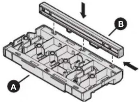
natural_image
Exploded view diagram of a mechanical housing assembly with labeled components A and B (no text or symbols beyond labels)natural_image
Technical line drawing of a mechanical housing component with hexagonal patterns and mounting holes (no text or symbols)3 Serrez le gabarit
natural_image
Diagram of a computer interface showing a cable inserted into a device with ports and connectors (no text or symbols visible)text_image
Technical diagram showing a tool inserted into a component with labeled parts 1, C, and Dtext_image
Technical diagram showing installation steps of a mechanical component with labeled parts and magnified detail viewtext_image
Technical diagram showing installation of a device with labeled components and a magnified inset view highlighting internal structure.Connector les gabarits ensemble
natural_image
Diagram of two mechanical components with bolt holes and a downward arrow indicating assembly (no text or symbols)Maintenance
natural_image
Technical line drawing of a mechanical housing component with hexagonal cutouts and mounting holes (no text or symbols)natural_image
Line drawing of a pair of pliers (no text or symbols)Abrazadera Lápiz

text_image
Exploded view diagram of a mechanical assembly with labeled parts A through Htext_image
Technical diagram of a device interior with labeled components A, C, D, and Gnatural_image
Pure geometric line drawing of a corner bracket (no text or symbols)
natural_image
Simple 3D line drawing of a corner bracket (no text or symbols)natural_image
Technical line drawing of a device casing with hexagonal panel and mounting holes (no text or symbols)natural_image
Technical line drawing of a mechanical device with attached components and a handle (no text or symbols)Armarios sin marco
text_image
Technical diagram of a mechanical component with labeled parts A and B, showing internal structure and assembly.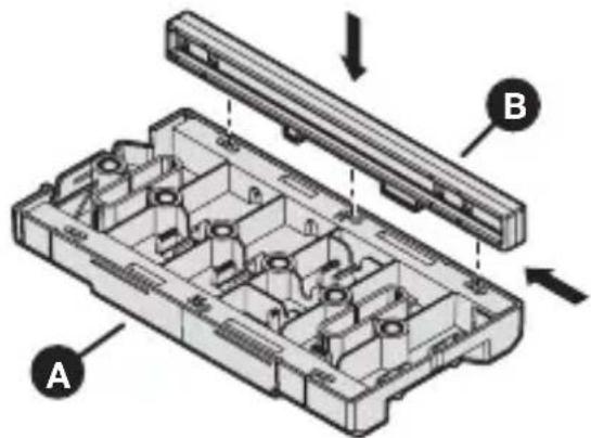
natural_image
Technical diagram of a mechanical assembly with labeled parts A and B, showing internal components without any text or symbols.natural_image
Technical line drawing of a mechanical housing component with hexagonal patterns and mounting holes (no text or symbols)natural_image
Diagram of a computer monitor with ports and cable, showing internal components and wiring (no text or labels)text_image
Diagram showing a power tool inserted into an electronic device with labeled parts 1, C, and Dtext_image
Technical diagram showing installation steps of a device with labeled components and a magnified inset viewtext_image
Technical diagram showing assembly steps of a device with labeled components and a magnified inset viewConexión de guías
natural_image
Diagram of two electronic component blocks with pins and a downward arrow indicating assembly or disassembly (no text or symbols present)Mantenimiento
natural_image
Technical line drawing of a mechanical housing component with hexagonal cutouts and mounting holes (no text or symbols)natural_image
Line drawing of a pair of pliers (no text or symbols)Serre-joint Crayon

text_image
Exploded view diagram of a mechanical component with labeled parts A through Htext_image
Technical diagram of a device interior with labeled components A, C, D, and Gnatural_image
Pure geometric line drawing of a corner bracket (no text or symbols)
natural_image
Simple 3D line drawing of a corner bracket (no text or symbols)natural_image
Technical line drawing of a mechanical housing component with hexagonal patterns and mounting holes (no text or symbols)natural_image
Technical diagram of a computer monitor with cable and socket ports, showing internal components and wiring (no text or labels)text_image
Technical diagram of a mechanical component with labeled parts A and B, showing internal structure and assembly.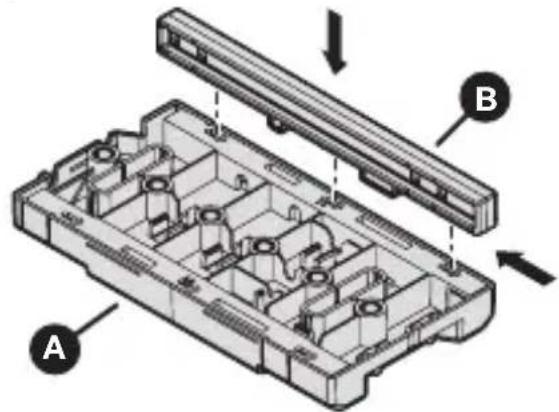
text_image
Technical diagram of a mechanical assembly with labeled components A and B, showing internal structure and directional arrows.natural_image
Technical line drawing of a mechanical housing component with hexagonal patterns and mounting holes (no text or symbols)natural_image
Diagram of a computer interface with a hand connecting ports to a panel (no text or symbols visible)text_image
Diagram showing a tool inserted into an electrical component with labeled parts 1, C, and Dtext_image
Technical diagram showing installation of a device with labeled components and a magnified inset detail viewtext_image
Technical diagram showing installation of a device with labeled components and a magnified inset view highlighting internal structure.natural_image
Two identical electrical connector blocks with circular terminals and a downward arrow indicating rotation (no text or symbols)Maintenance
natural_image
Technical line drawing of a mechanical housing component with hexagonal cutouts and mounting holes (no text or symbols)natural_image
Line drawing of a pair of pliers (no text or symbols)Pinza Lápiz
text_image
Exploded view diagram of a mechanical component with labeled parts A through Htext_image
Technical diagram of a device casing with labeled components A, C, D, and Gnatural_image
Pure geometric line drawing of a corner bracket (no text or symbols)
natural_image
Simple 3D line drawing of a corner bracket (no text or symbols)natural_image
Technical line drawing of a device casing with hexagonal panel and mounting holes (no text or symbols)natural_image
Technical line drawing of a computer tower with attached cables and connectors (no text or symbols)Muebles sin marco
text_image
Technical diagram of a mechanical component with labeled parts A and B, showing internal structure and assembly.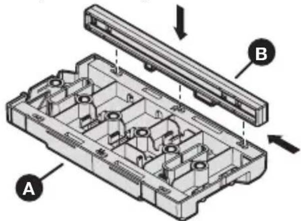
text_image
Technical diagram of a device housing with labeled components A and B, showing internal compartments and mounting points.natural_image
Technical line drawing of a mechanical housing component with hexagonal patterns and mounting holes (no text or symbols)natural_image
Diagram of a computer interface with a cable inserted and a hand adjusting the panel (no text or symbols visible)text_image
Diagram showing a soldering tool inserted into an electrical component with labeled parts 1, C, and Dtext_image
Technical diagram showing installation of a device with labeled components and a magnified inset viewtext_image
Technical diagram showing installation of a device with labeled components and a magnified inset highlighting a component detail.Unión de plantillas
natural_image
Diagram of two electronic component blocks with pins and a downward arrow indicating assembly or disassembly (no text or symbols present)Mantenimiento
natural_image
Technical line drawing of a mechanical housing component with hexagonal cutouts and mounting holes (no text or symbols)text_image
Exploded view diagram of a mechanical component with labeled parts A through Htext_image
Technical diagram of a device interior with labeled components A, C, D, and Gnatural_image
Pure geometric line drawing of a corner bracket without any text, numbers, or symbols
natural_image
Simple 3D line drawing of a corner bracket (no text or symbols)natural_image
Technical line drawing of a mechanical housing component with hexagonal patterns and mounting holes (no text or symbols)natural_image
Diagram of a computer monitor with ports and cables, showing internal components without any text or symbolsRahmenlose Schränke
text_image
Technical diagram of a mechanical component with labeled parts A and B, showing internal structure and assembly.