Deck Jig - Drill Kreg - Free user manual and instructions
Find the device manual for free Deck Jig Kreg in PDF.
User questions about Deck Jig Kreg
0 question about this device. Answer the ones you know or ask your own.
Ask a new question about this device
Download the instructions for your Drill in PDF format for free! Find your manual Deck Jig - Kreg and take your electronic device back in hand. On this page are published all the documents necessary for the use of your device. Deck Jig by Kreg.
USER MANUAL Deck Jig Kreg
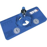
Deck Jig™ Concealed Fastening System
Manual applies to Item # KJDECKSYS20
natural_image
Technical line drawing of a mechanical assembly with exploded view, showing internal components and assembly parts (no text or symbols)WARNING Every user must read and follow instructions and safety precautions in this manual.
Failure to do so could result in serious injury. Save manual for future reference.
We're here to help.
We want you to have an exceptional project building experience.
If you have questions or need support, please get in touch.
1-800-447-8638 | technicalsupport@kregtool.com
Tell us about your experience.
Your opinion counts. And we're always looking for ways to improve.
Share your feedback so we can keep growing and innovating for you.
www.kregtool.com/feedback
English 2
French 17
Spanish 33
Table of Contents
Safety Precautions....2
Pre-Assembly 3
Recommended Tools/Materials
(Not Included) 3
Product Description 3
Jig Assembly 4
Depth Collar Setup 5
Operation 7
Hole Placement 9
Drilling a Splice Joint. 10
Drilling Stair Treads. . . . . . . . . . . . . . 11
Using Spacer Rings 12
Choosing a Deck ..... 13
Decking Material ..... 13
Deck Screws .....13
Service Parts .....14
Accessories. 14
Online Resources. 14
Safety Precautions
WARNING Before using a power tool with this product, read and follow the tool manufacturer's instructions and safety precautions in addition to the safety precautions below to reduce the risk of serious injury from hazards such as fire, electric shock, or rotating drill bit.
■ Always wear personal protective equipment recommended by the manufacturer of the power tool you are using, such as eye, hearing, or respiratory protection.
■ The drill bit is sharp. Handle with care.
■ Do not allow familiarity gained from frequent use of your tools to replace safe work practices. A moment of carelessness is sufficient to cause serious injury.
■ Avoid awkward hand positions where a sudden slip could cause contact with the rotating bit.
WARNING Do not operate this tool or any machinery while under the influence of drugs, alcohol, or medications.
WARNING This product can expose you to chemicals including Acrylonitrile and other chemicals, which are known to the State of California to cause cancer and reproductive harm. For more information go to www.P65Warnings.ca.gov.
Pre-Assembly
Review this section before you begin. Ensure you have all tools/materials on hand and compare the package with the items listed in the Hardware Included and Product Description sections. If any item appears missing or lost, do not use this product. Contact Kreg Technical Support or return product to place of purchase.
Recommended Tools/Materials (Not Included)
natural_image
Illustration of a screwdriver with a plus symbol and a circular head (no text or labels)2 Phillips Screwdriver
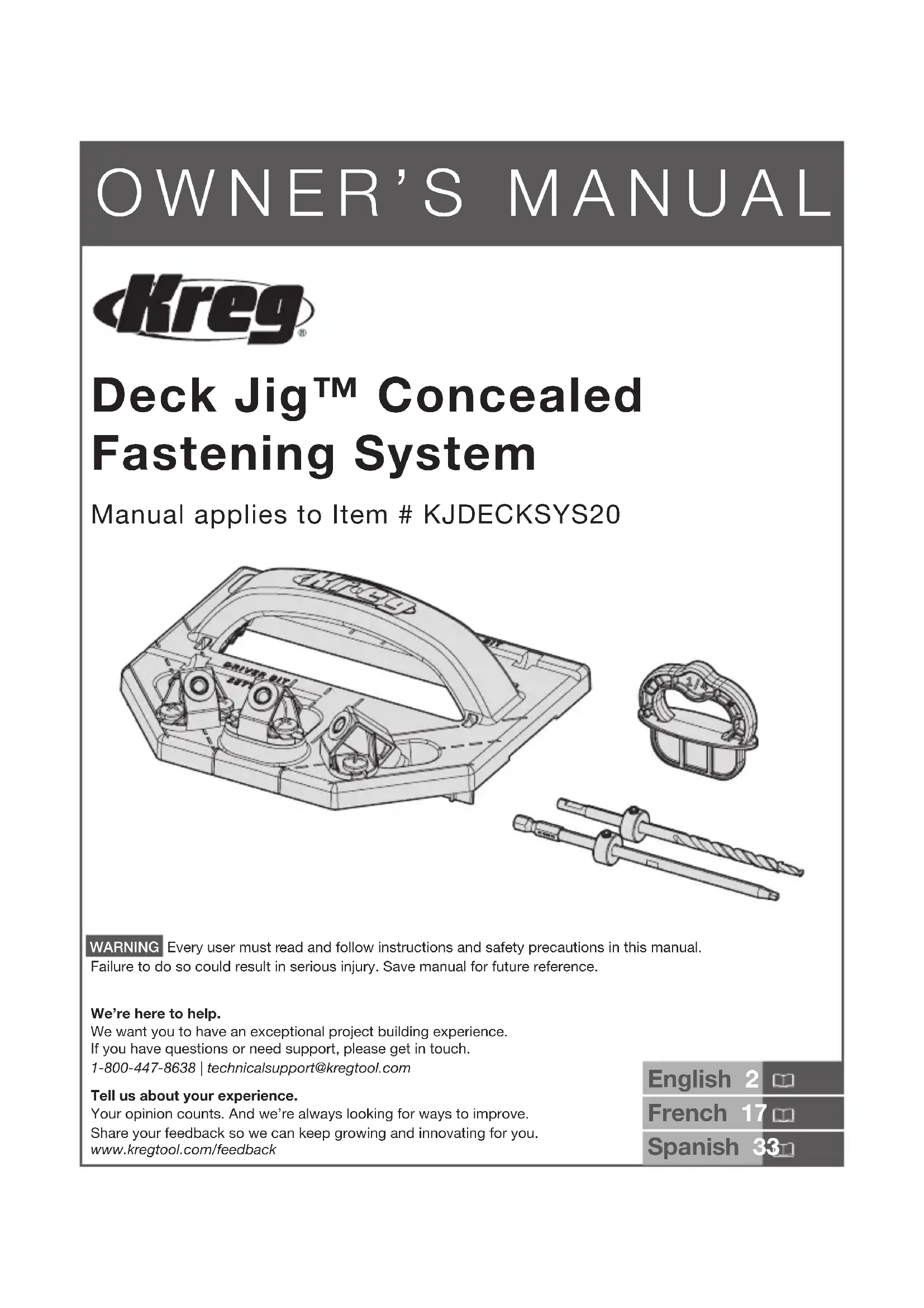
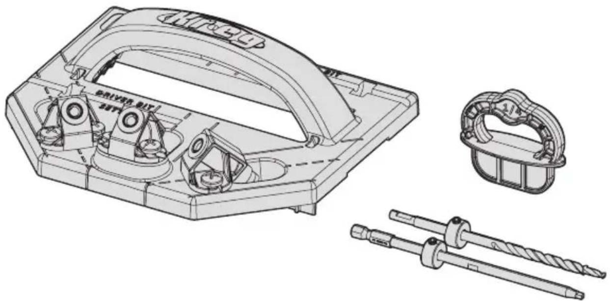
Product Description
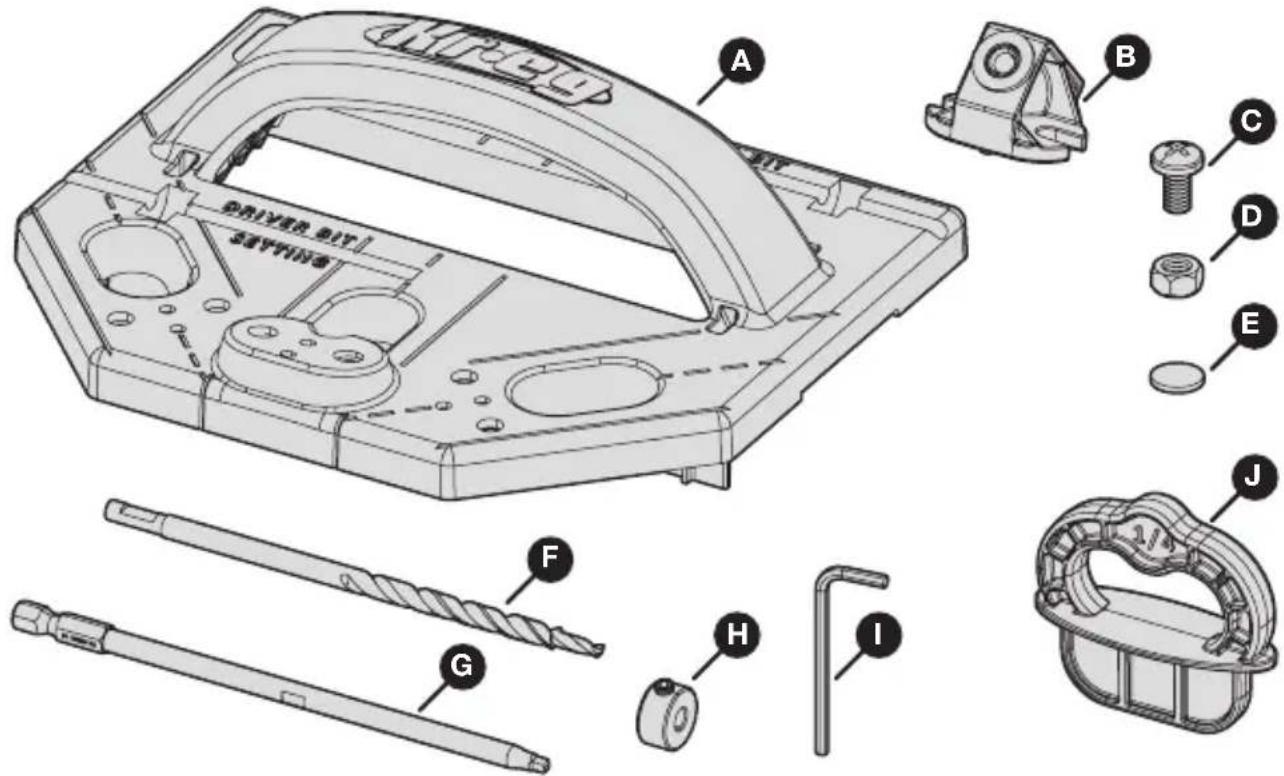
text_image
DRIVER BIT SAVING A B C D E F G H I J| Part Description Part Description | ||
| A Deck Jig F 6" Deck Jig drill bit | ||
| B Drill guide (3) G 6" KTX square driver bit | ||
| C Drill-guide screw (6) H Depth collar (2) | ||
| D Drill-guide nut (6) I Hex wrench | ||
| E Rubber foot (6 plus 4 extra) J 1/4" Spacer ring (3) |
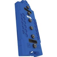
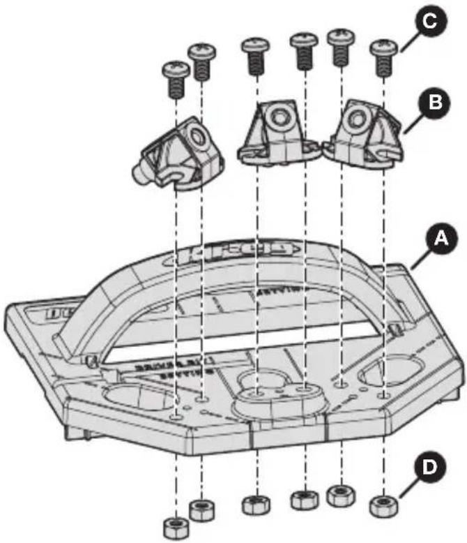
Jig Assembly
1 Attach the Drill Guides to the Deck Jig
The Deck Jig includes three drill guides. Each drill guide attaches to a pair of mounting holes on the Deck Jig.
a. Turn the Deck Jig (A) upside down and locate a pair of mounting holes for a drill guide.
Note There are three pairs of mounting holes (one pair per drill guide).
b. Insert two drill-guide nuts (D) into the pair of mounting holes on the bottom of the Deck Jig (A).
c. Holding the drill-guide nuts (D) in place, turn the Deck Jig (A) right-side up and place a drill guide (B) into position over those two mounting holes.
d. Insert a drill-guide screw (C) into each of the two mounting holes and use a #2 Phillips screwdriver to tighten the screws firmly.
e. Repeat these steps to attach the two remaining drill guides (B) to the Deck Jig (A).
text_image
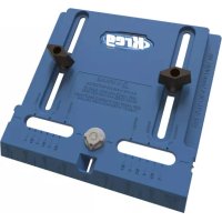
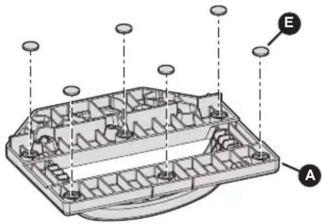
Technical diagram of a mechanical assembly with labeled parts A, B, C, and D showing bolted components and structural details.2 Adhere the Rubber Feet to the Deck Jig
Remove rubber feet (E) from the backing sheet and adhere them to the six designated locations on the bottom of the jig (A).
Note The rubber feet help prevent the jig from slipping on the boards.
text_image
Technical diagram of a device casing with labeled components A and E, showing internal compartments and mounting points.Depth Collar Setup
Before drilling your first hole, you must set the depth collar on both the drill bit and the driver bit. The depth collars help you achieve the proper hole and screw depth, ensuring the strongest possible joint with minimal exposure to the elements.
Note Follow the instructions for either non-grooved or grooved decking, depending on the type of boards you are using for your project.
Tip After initial depth collar setup, check the settings from time to time to ensure that each depth collar is still set correctly.
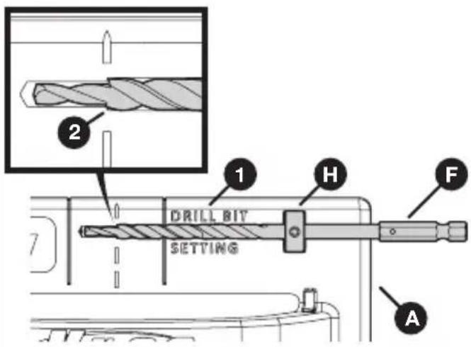
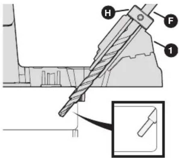
1 Set the Depth Collar on the Drill Bit
This depth collar controls hole depth and the position where the "shoulder" stops the screw.
For non-grooved decking:
a. On the Deck Jig (A), locate the gauge (1) labeled "Drill Bit Setting."
b. Place a depth collar (H) into the recessed slot and use a hex wrench (I) to hold it in position.
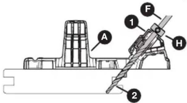
c. Slide the drill bit (F) through the depth collar (H) until the shoulder (2) of the drill bit (F) aligns with the dashed line.
d. Use the hex wrench (I) to tighten the depth collar (H) to the drill bit (F) securely.
text_image
2 1 DRILL BIT H F SETTING AFor grooved decking:
a. Place the Deck Jig (A) at the end of a grooved deck board.
b. Slide the drill bit (F) into the center drill guide (1) until the drill bit shoulder (2) is even with the bottom of the groove in the deck board.
c. Holding the drill bit (F) in this position, slide the depth collar (H) onto the drill bit (F) until the depth collar (H) rests against the drill guide (1).
d. Use the hex wrench (I) to tighten the depth collar (H) to the drill bit (F) securely.
text_image
A 1 F H 22 Set the Depth Collar on the Driver Bit
This depth collar controls the depth of your screw. When set properly, this depth collar prevents you from over-driving the screw.
For non-grooved decking:
a. On the Deck Jig (A), locate the gauge (1) labeled "Driver Bit Setting."
b. Place a depth collar (H) into the recessed slot and use a hex wrench (I) to hold it in position.
c. Slide the driver bit (G) through the depth collar (H) until the square tip (2) of the driver bit (G) aligns with the dashed line of the center drill guide.
d. Use the hex wrench (I) to tighten the depth collar (H) to the driver bit (G) securely.
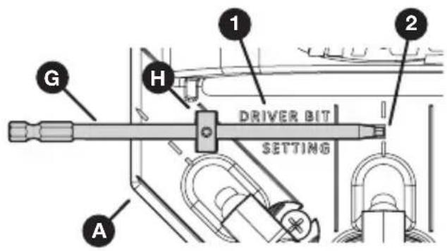
text_image
1 2 G H DRIVER BIT SETTING AFor grooved decking:
a. Place the Deck Jig (A) at the end of a grooved deck board.
b. Slide the driver bit (G) into the center drill guide (1) until the square tip (2) of the driver bit (G) is even with the bottom of the groove in the deck board.
c. Holding the driver bit (G) in this position, slide the depth collar (H) onto the drive bit (G) until the depth collar (H) rests against the drill guide (1).
d. Use the hex wrench (I) to tighten the depth collar (H) to the driver bit (G) securely.
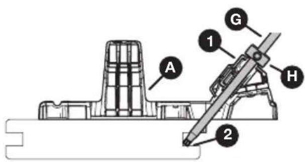
text_image
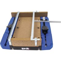
A 1 G H 2Operation
The Kreg Deck Jig allows you to drill a specialized hole at an optimized angle to secure your deck boards to the deck joists.
The hole is created by a stepped (or shouldered) drill bit which drills the pocket hole and pilot hole for the screw in one simple motion. The depth of the hole is controlled by a depth collar.
The Kreg Deck Jig also guides your screw as it is driven, so that the screw follows the exact path necessary and so that you won't overdrive or under-drive the screw.
Important! Driving your screws without the use of the depth collar and/or the Kreg Deck Jig can cause over-driving. Over-driving can lead to a joint with significantly reduced strength and increases the potential for excessive moisture build-up on the screw head.
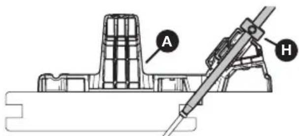
1 Before You Begin
a. Check the depth collars:
■ Ensure that a depth collar (H) is securely attached to the drill bit (F) and to the driver bit (G).
■ Ensure that the placement of each depth collar (H) is appropriate for your decking (either non-grooved or grooved).
Note See Depth Collar Setup on page 5.
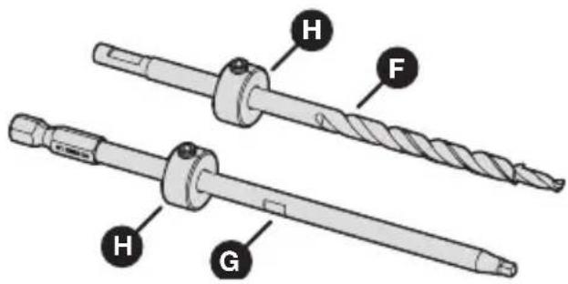
text_image
H F H Gb. For grooved decking: Test the screw placement:
With the depth collars set on the drill bit and driver bit, test-drive a deck screw into a scrap of grooved decking and check the results:
■ The bottom of the screw head should bear against the bottom lip of the groove.
■ None of the screw shank should be exposed, but the head should not be buried.
Make any necessary adjustments to the position of the driver bit stop collar; then retest the screw placement.
text_image
A HNote Ensure that the screw head is not buried. Burying the screw head in the bottom lip of the groove could cause the lip to split.
2 Drill a Pocket Hole and Pilot Hole
a. Align the appropriate drill guide (1) over the deck board.
Note Review the recommendations in Hole Placement on page 9 for guidance on which drill guide is best for a given hole.
b. Place the drill bit (F) with attached depth collar (H) into your drill.
c. Insert the drill bit (F) into the drill guide (1) and bring your drill up to speed before contacting the deck board to ensure correct rotation of the driver bit.
d. Drill until the depth collar (H) contacts the drill guide (1).
e. Remove the drill bit (F) from the drill guide (1) while the drill bit is still rotating.
text_image
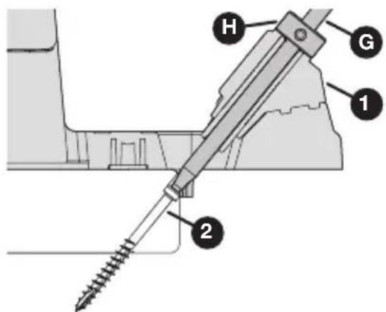
Technical diagram of a mechanical assembly with labeled parts H, F, and 1, showing a detailed detail view.3 Drive a Screw
Note For information on choosing deck screws, see Deck Screws on page 13.
a. Place the driver bit (G) with attached depth collar (H) into your drill.
b. Realign the drill guide (1) with the hole that you just drilled.
c. Place a screw (2) directly into the drill guide (1).
d. Ensure that the screw (2) is correctly positioned to enter the hole; then drive the screw (2) when ready.
e. Drive the screw (2) until the depth collar (H) on the driver bit (G) reaches the drill guide (1).
text_image
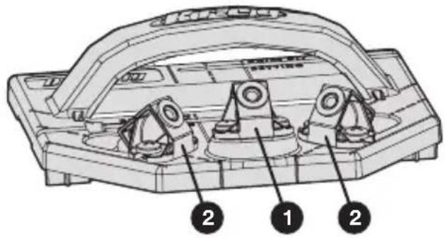
H G 1 2Hole Placement
The Kreg Deck Jig provides three drill guides to accommodate different situations: a center guide (1) and two angled guides (2).
General guidelines:
■ Whenever possible, use the center guide (1) in the center of the joist. This hole placement provides the strongest joint.
■ When the edge is obstructed or when you are splicing two boards on the center of a joist, use either of the angled guides (2).
■ When you cannot position the jig effectively, drive a face-screw to secure the board.
text_image
Technical diagram of a mechanical component with numbered parts labeled 1, 2, and 3Specific situations are described below
Note The suggestions in this section are provided as guidance, only.
When you are screwing along the length of the board with no obstructions, use the center drill guide (1) aligned with the center of the joist.
Note This hole placement is the most common type.
text_image
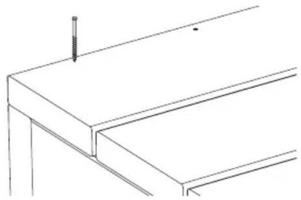
Technical diagram of a mechanical component with labeled parts and numbered annotationObstructed edge
When the edge of your deck board is obstructed by a wall, or when the edge is on the outside of the deck where you cannot use angled holes, drive your screws from the top side of the deck board (face-screw).
natural_image
Technical line drawing of a structural beam with a screw and support (no text or symbols)Drilling Ends
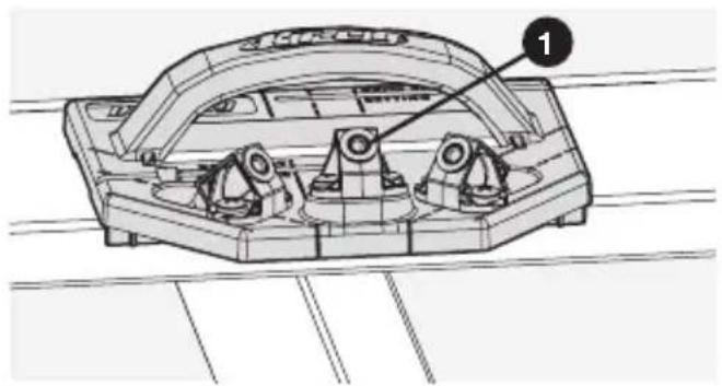
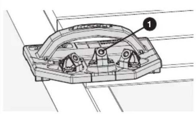
Unobstructed end
When you are securing the end of a board and you can position the Deck Jig past the board (that is, when the Deck Jig is not obstructed by a wall), use the center drill guide (1) for superior strength.
natural_image
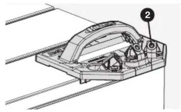
Technical line drawing of a mechanical component with labeled part '1' (no text or symbols beyond label)Obstructed end
When you are securing the end of a board but the Deck Jig cannot be positioned past the board because of a wall obstruction, use either of the angled drill guides (2), as shown.
natural_image
Technical line drawing of a mechanical assembly with labeled component (no readable text or symbols)Drilling 45° Decking
When you are securing deck boards at a 45^ angle from the joists, place the center drill guide (1) at the intersection of the joist and the deck board.
Then drill using the dashed line as an alignment guide.
text_image
DEUT JU BEETJU BEETJU BEETJU BEETJU BEETJU BEETJU BEETJU BEETJU BEETJU BEETJU BEETJU BEETJU BEETJU BEETJU BEETJU BEETJU BEETJU BEETJU BEETJU BEETJU BEETTJU BEETTJU BEETTJU BEETTJU BEETTJU BEETTJU BEETTJU BEETTJU BEETTJU BEETTJU BEETTJU BEETTJU BEETTJU BEETTJU BEETTJU BEETTJU BEETTJU BEEUT JU BEEUT JU BEEUT JU BEEUT JU BEEUT JU BEEUT JU BEEUT JU BEEUT JU BEEUT JU BEEUT JU BEEUT JU BEEUT JU BEEUT JU BEEUT JU BEEUT JU BEEUT JU BEEUT JU BeeUT JU BeeUT JU BeeUT JU BeeUT JU BeeUT JU BeeUT JU BeeUT JU BeeUT JU BeeUT JU BeeUT JU BeeUT JU BeeUT JU BeeUT JU BeeUT JU BeeUT JU BeeUT JU BeeUT JUDrilling a Splice Joint
When you are creating a splice at the center of a joist, use an angled drill guide (2) to get the strongest joint possible.
For correct hole placement, align the edge of the jig with the splice, as shown.
text_image
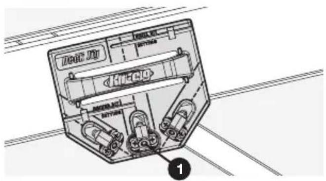
2Drilling Stair Treads
Start at the bottom of the stairs and work your way up so that you always have room to drill holes and drive screws.
If you plan to put risers on the stairs, install all the treads before you install the risers.
For the inner tread:
■ Use either of the angled drill guides for the inner long edge (1).
text_image
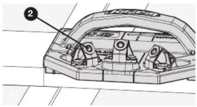
Technical diagram of a mechanical component with labeled parts and an arrow indicating direction, marked with number 1.■ Use the center drill guide for the outer long edge (2).
text_image
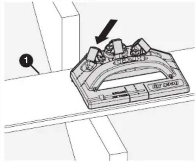
Technical diagram of a mechanical component with labeled parts and an arrow indicating directionFor the outer tread:
■ Use either of the angled drill guides for the inner long edge (3).
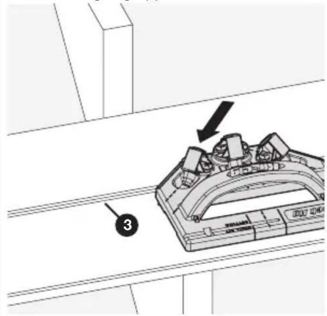
text_image
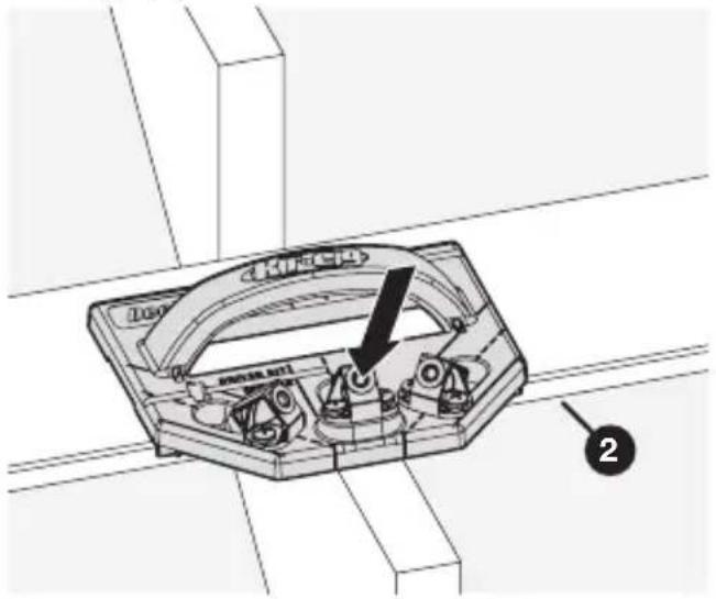
Technical diagram showing a mechanical component with labeled parts and an arrow indicating direction, marked with number 3.■ Drive a face-screw for the outer long edge (4).
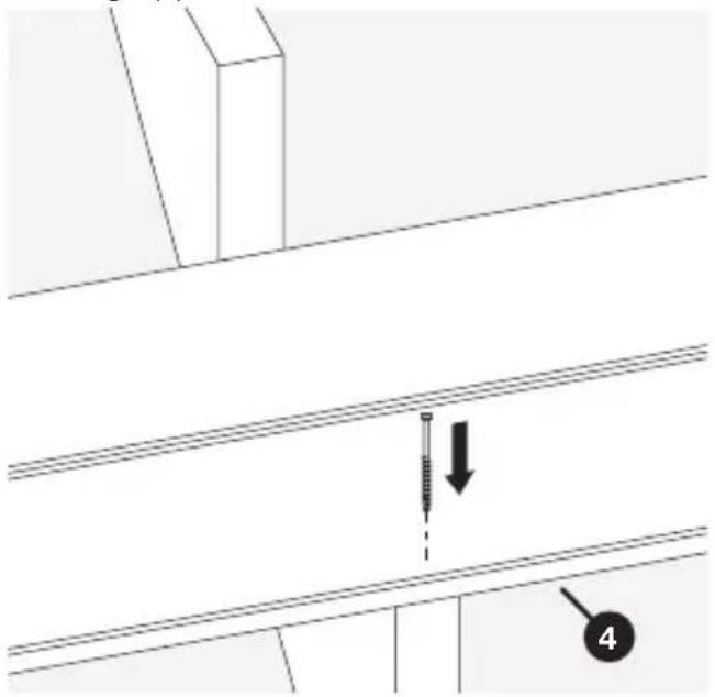
text_image
Technical diagram showing a screw installation with labeled component '4' and directional arrow indicating assembly or inspection.Using Spacer Rings
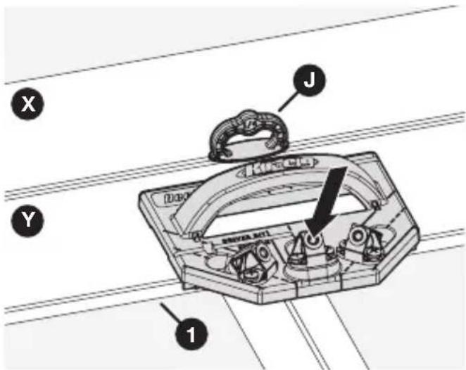
Three 1/4" spacer rings are included with your Deck Jig. These spacer rings act as a guide to help you create consistent spacings between one deck board and the next.
Building your deck with the proper 1/4" minimum spacing between boards allows debris to fall through for a clean deck. More importantly, the spacing ensures proper air movement to reduce moisture buildup.
Tip Also check your decking manufacturer's spacing recommendations.
a. Place the spacers (J) between a secured board (X) and an adjacent unsecured board (Y).
b. Using the Deck Jig, drill holes and drive screws into all the joists along the outer edge (1) of the unsecured board (Y).
Note Always drill the edge of the board that is opposite the spacers first (that is, the outer edge), so that the pressure of drilling and driving pushes toward the spacers.
c. Remove the spacers (J).
d. Drill holes and drive screws into all the joists along the inner edge (2) of the unsecured board (Y).
Note Now the pressure of drilling and driving pushes back against the edge of the board that is already held in place by the screws (3).
text_image
X Y J Duro S###BA ACTI 1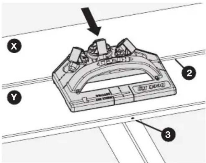
text_image
Technical diagram of a mechanical component with labeled parts X, Y, and numbered parts 2, 3Choosing a Deck
This section describes some considerations to take into account when selecting material and screws for your deck.
Decking Material
The Kreg Deck Jig works with almost any type of decking material. These types are some of the most popular materials:
■ ACQ pressure-treated lumber: Usually made from pine, “Green Treat” lumber is one of the most affordable types of decking material. This material commonly suffers from shrinking, swelling, and splitting. It will not last as long as many other types of decking.
■ Composite Material: Composite decking is often made from a combination of wood fibers and plastic. It is more expensive than pine, but lasts much longer and is less prone to shrinking, swelling, and splitting. Composite is our recommended decking material.
■ Exotic Hardwoods: Exotic woods such as ipe are much harder and more dense than traditional pine. As a result, they last longer, look better, and cost more. Exotic woods still require treatment to prevent discoloration and water damage.
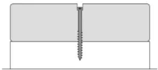
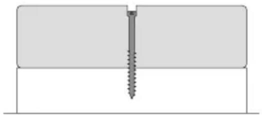
Deck Screws
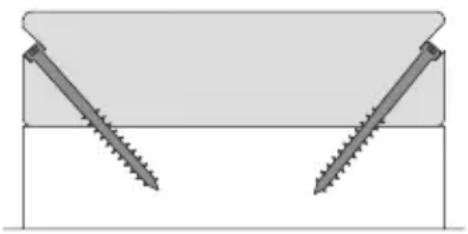
Kreg Deck Screws were designed specifically for use as concealed fasteners with the Kreg Deck Jig. These screws can also be used as simple face-screws for a variety of outdoor projects.
natural_image
Diagram showing two screws inserted into a rectangular block, forming an inverted V-shape (no text or symbols)Concealed Face-screw (visible)

natural_image
Pure technical diagram of a screw fastening inside a rectangular block (no text or symbols)Protection from Corrosion
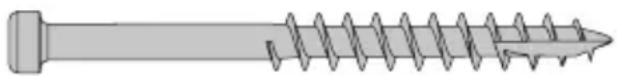
Kreg Deck Screws are available in two types:
■ Protec-Kote™: Three anti-corrosion layers protect against rusting in a wide variety of decking applications; perfect for ACQ-treated lumber.
■ Stainless: For even more protection, choose stainless. Stainless screws provide the best long-term protection against corrosion and are suited for marine applications.
Screw Length
Choose the screw length based on the thickness of your decking material.
| Material Thickness Screw Length | |
| 4/4 to 5/4 (3/4" to 1-1/8") 2" | |
| 1-1/2" 2-5/8" |
Service Parts
If you need help with parts for your Kreg Deck Jig, contact Kreg Technical Support.
Accessories
Kreg Protec-Kote™ Deck Screws Kreg Stainless Deck Screws
natural_image
Illustration of a screw with threaded shaft and threaded end (no text or symbols)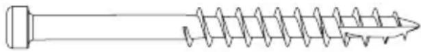
natural_image
Line drawing of a screw with helical end (no text or symbols)Online Resources
■ Instructional video: Visit https://www.youtube.com/watch?v=Ft50pR-V0DY and follow along as master carpenter Gary Streigler demonstrates how to use the Kreg Deck Jig.
Kreg website: Visit www.kregtool.com for everything Kreg. Whether you need to review a particular step or order a box of Kreg Deck Screws, this site is where you'll find it.
Kreg Owners Community: Visit kregjig.ning.com to see what other Kreg Deck Jig owners are building, get your questions answered in the forums, and sign up to receive the Kreg Plus Newsletter.

text_image
Kreg®EXPLORE. BUILD. SHARE.
We're makers just like you.
That's why we love to see what you're working on.
Share with the community and get inspired!
madewithKreg
Get free plans, project resources, and more. kregtool.com and buildsomething.com
GUIDE D'UTILISATEUR

text_image
Kreg®natural_image
Technical line drawing of a mechanical assembly with exploded view, showing internal components and assembly parts (no text or symbols)natural_image
Illustration of a screwdriver with a plus symbol (no text or labels)text_image
A B C D E F G H I J DRIVER BIT SAYINGtext_image
Technical diagram of a mechanical assembly with labeled parts A, B, C, and D, showing bolted components and structural details.text_image
Technical diagram of a device casing with labeled components A and E, showing internal compartments and mounting points.text_image
1 2 G H DRIVER BIT SETTING Atext_image
A 1 G H 2Fonctionnement
text_image
Technical diagram of a mechanical assembly with labeled parts H, F, and 1, showing a tool interacting with a component.text_image
Technical diagram of a mechanical component with numbered parts labeled 1, 2, and 3Bord sans obstruction
text_image
Technical diagram of a mechanical component with labeled parts and numbered annotationnatural_image
Technical line drawing of a structural beam with a screw and support (no text or symbols)natural_image
Technical line drawing of a mechanical component with labeled part '1' (no text or symbols beyond label)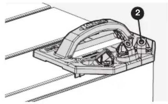
natural_image
Technical line drawing of a mechanical assembly with labeled component (no readable text or symbols)text_image
1 SINNAN SINNANtext_image
Technical diagram of a mechanical device with labeled parts and directional arrow indicating rotation or movementtext_image
Technical diagram showing a mechanical component with labeled parts and an arrow indicating direction, marked as item 3.text_image
Technical diagram showing a screw installation with labeled component '4' and directional arrow indicating motiontext_image
X Y J Dak SRAE AFL 1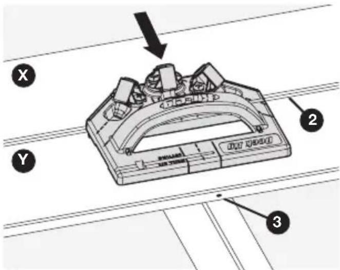
text_image
Technical diagram of a mechanical component with labeled parts X, Y, and numbered parts 2, 3natural_image
Diagram showing two screws inserted into a rectangular block, forming an inverted V-shape (no text or symbols)Invisible Vis apparente (visible)
natural_image
Pure technical diagram of a screw fastening inside a rectangular block (no text or symbols)natural_image
Illustration of a screw with threaded shaft and threaded end (no text or symbols)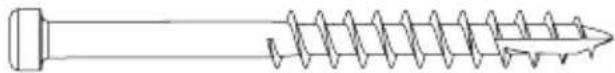
natural_image
Line drawing of a screw with threaded shaft and threaded end (no text or symbols)Ressources en ligne
natural_image
Technical line drawing of a mechanical assembly with exploded view, showing internal components and assembly parts (no text or symbols)natural_image
Illustration of a screwdriver with a plus symbol and a circular cross symbol (no text or labels)Destornillador Phillips No. 2
text_image
DRIVER BIT SETTING A B C D E F G H I Jtext_image
Technical diagram of a mechanical assembly with labeled parts A, B, C, and D, showing bolted components and structural details.text_image
Technical diagram of a mechanical component with labeled parts A and E, showing internal structure and alignment indicators.text_image
1 2 G H DRIVER BIT SETTING Atext_image
A 1 G H 2Funcionamiento
text_image
Technical diagram of a mechanical assembly with labeled parts H, F, and 1, showing a detailed inset view.3 Introduzca el tornillo
text_image
Technical diagram of a mechanical component with numbered parts labeled 1, 2, and 3text_image
Technical diagram of a mechanical component with labeled parts and numbered annotationnatural_image
Technical line drawing of a structural component with a screw and mounting bracket (no text or symbols)natural_image
Technical line drawing of a mechanical component with labeled part '1' (no text or symbols beyond label)natural_image
Technical line drawing of a mechanical assembly with labeled component (no readable text or symbols)text_image
DEUT JQ HECO 1text_image
Technical diagram of a mechanical device with labeled parts and directional arrow indicating rotation or movementtext_image
Technical diagram showing a mechanical component with labeled parts and an arrow indicating direction, marked as item 3.text_image
Technical diagram showing a screw installation with labeled component '4' and directional arrow indicating motiontext_image
X Y J Dak SRAE AFL 1
text_image
Technical diagram of a mechanical component with labeled parts X, Y, and numbered parts 2, 3natural_image
Diagram showing two screws inserted into a rectangular block (no text or symbols)Oculto Tornillo frontal (visible)
natural_image
Pure technical diagram of a screw fastening inside a rectangular block (no text or symbols)natural_image
Illustration of a screw with threaded shaft and threaded end (no text or symbols)