KMA4100 - Electric saw Kreg - Free user manual and instructions
Find the device manual for free KMA4100 Kreg in PDF.
| Product Type | Crosscut Station for Circular Saw |
| Brand | Kreg |
| Model | KMA4100 |
| Category | Electric Saw (Accessory) |
| Materials | Plastic and Metal |
| Cutting Capacity | Up to 45° angle, 90° cuts |
| Compatibility | Portable Circular Saws |
| Adjustable Guide | Yes, with angle indicators from 0° to 45° |
| Clamps | Included, to secure the workpiece |
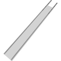
| Long Workpiece Support | Side Wings with Detachable Blocks |
| Sure-Cut™ Cutting Board | Yes, replaceable |
| Non-Slip Grip | Sure-Grip™ Pads under the base |
| Workbench Attachment | Possible via holes in the side rails |
| Maximum Cutting Depth | 5 cm (2 inches) for the kerf |
| Maintenance | Clean dust and debris from all surfaces |
| Safety | Read warnings, wear PPE, do not cut small pieces |
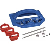
| Package Contents | Base, rails, wings, Sure-Cut board, clamps, guide, hardware |
| Warranty | Consult the manufacturer |
Frequently Asked Questions - KMA4100 Kreg
User questions about KMA4100 Kreg
0 question about this device. Answer the ones you know or ask your own.
Ask a new question about this device
Download the instructions for your Electric saw in PDF format for free! Find your manual KMA4100 - Kreg and take your electronic device back in hand. On this page are published all the documents necessary for the use of your device. KMA4100 by Kreg.
USER MANUAL KMA4100 Kreg
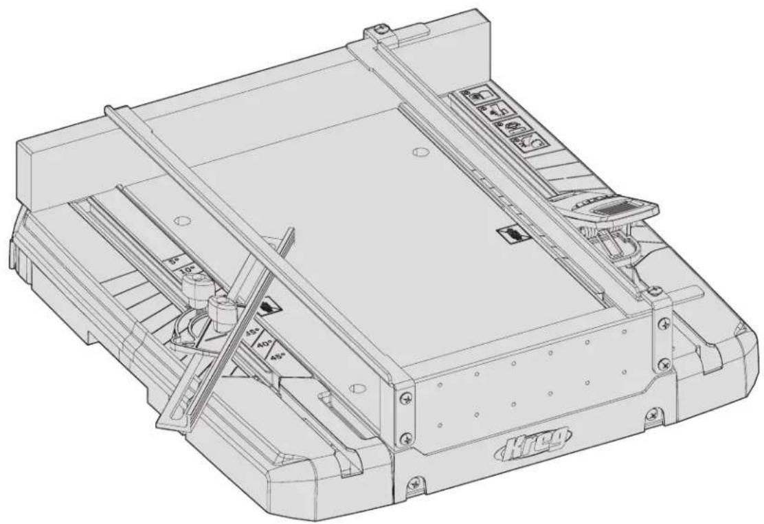
Manual applies to Item # KMA4100 and KMA4100-INT
natural_image
Technical line drawing of a mechanical assembly with no visible text or symbolsWARNING Every user must read and follow instructions and safety precautions in this manual.
Failure to do so could result in serious injury. Save manual for future reference.
We're here to help.
We want you to have an exceptional project building experience.
If you have questions or need support, please get in touch.
1-800-447-8638 | technicalsupport@kregtool.com
Tell us about your experience.
Your opinion counts. And we're always looking for ways to improve.
Share your feedback so we can keep growing and innovating for you.
www.kregtool.com/feedback
| English 2 | |
| French (N. America) | 11 |
| Spanish (N. America) | 21 |
| French 31 | |
| Spanish 41 | |
| German 51 |
Table of Contents
Safety Precautions 2
Pre-Assembly 2
Recommended Tools (Not Included). ..... 3
Hardware Included. 3
Product Description....3
Assembly 4
Operation 6
Make your Kerf Line Cut . . . . . . . . . . . . . 6
Make a 90° Cut 7
Cut Different Angles 8
Cut Long Workpieces 8
Care and Cleaning 9
Troubleshooting....9
Safety Precautions
WARNING Before using a power tool with this product, read, and follow the tool manufacturer's instructions and safety precautions in addition to the safety precautions below to reduce risk of serious injury from hazards such as fire, electric shock, or rotating saw blade.
- Follow your saw manufacturer's instructions and safety precautions.
■ Always wear personal protective equipment required by the saw manufacturer.
■ Do not allow familiarity gained from frequent use of your tools to replace safe work practices. A moment of carelessness is sufficient to cause serious injury.
■ Avoid awkward hand positions where a sudden slip could cause contact with the rotating blade.
■ This product is only intended for use with circular saws. Not intended for use with other power tools such as routers or jig saws.
■ Always secure the cutting station to prevent movement while cutting.
■ Do not attempt bevel cuts with this product.
■ Inspect your workpiece before cutting. If the workpiece is bowed or warped, ensure there is no gap between the workpiece and fence along the cut line.
■ Always secure the workpiece with a firm grip ensuring your hand stays outside of the cutting area as designated by the symbol.

WARNING Do not operate this tool or any machinery while under the influence of drugs, alcohol, or medications.
WARNING This product can expose you to chemicals including Acrylonitrile, which is known to the State of California to cause cancer. For more information go to www.P65Warnings.ca.gov.
WARNING Drilling, sawing, sanding or machining wood products can expose you to wood dust, a substance known to the State of California to cause cancer. Avoid inhaling wood dust or use a dust mask or other safeguards for personal protection. For more information go to www.P65Warnings.ca.gov/wood.
Pre-Assembly
WARNING Avoid cutting irregular-shaped workpieces that can twist, rock, or slip while being cut.
Review this section before you begin. Ensure you have all tools/materials that were in the package on hand and compare them with the items listed in the Hardware Included and Product Description sections. If any item is missing, do not use this product. Contact customer service or return product to place of purchase.
Recommended Tools (Not Included)
Phillips Screwdriver
Hardware Included

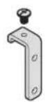
Top Screw - 2
CC - Large Screw - 4AA - Small Screw - 12 BB - Rail Bracket with
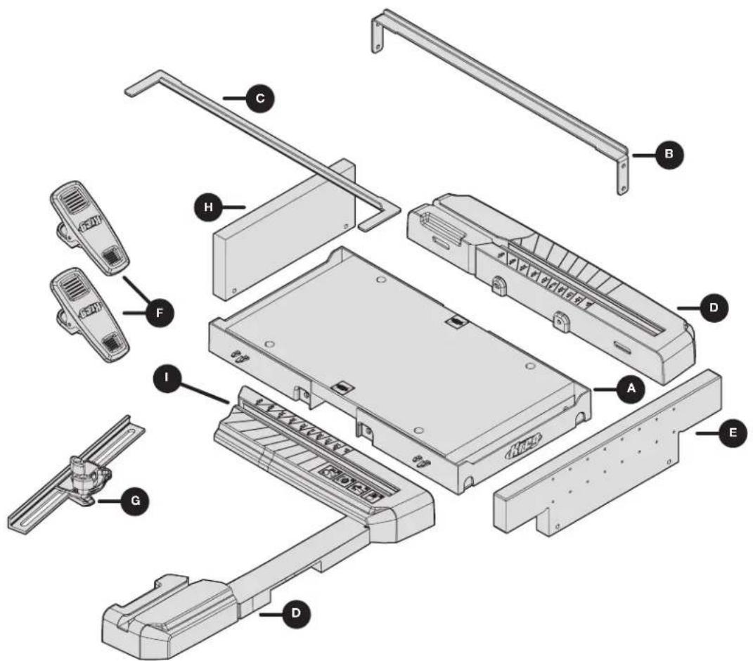
Product Description
text_image
Exploded view diagram of a device with labeled parts including chassis, chassis unit, and accessoriesPart Description Part Description
| A Cutting base F Material hold-down clamps |
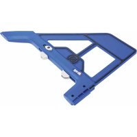
| B Fixed saw guide rail G Adjustable fence |
| C Adjustable saw guide rail H Front blade guard actuato |
| D Material support wings with detachable blocks I Angle |
| E Sure-CutTM back board |
| board | |
| dicators |
Assembly
Complete the steps in this section to assemble your Crosscut Station.
1 Attach the Material Support Wings
a. Attach the right and left material support wings (D) to the cutting base (A) using four small screws (AA).
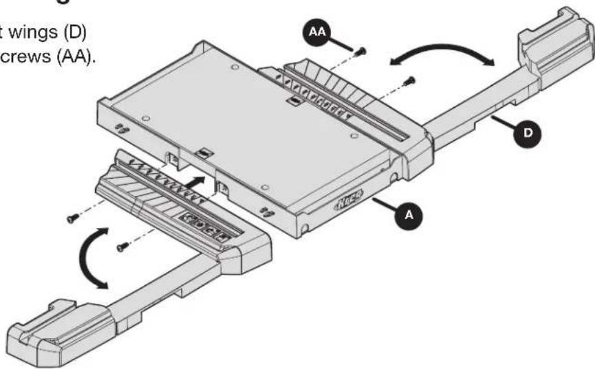
text_image
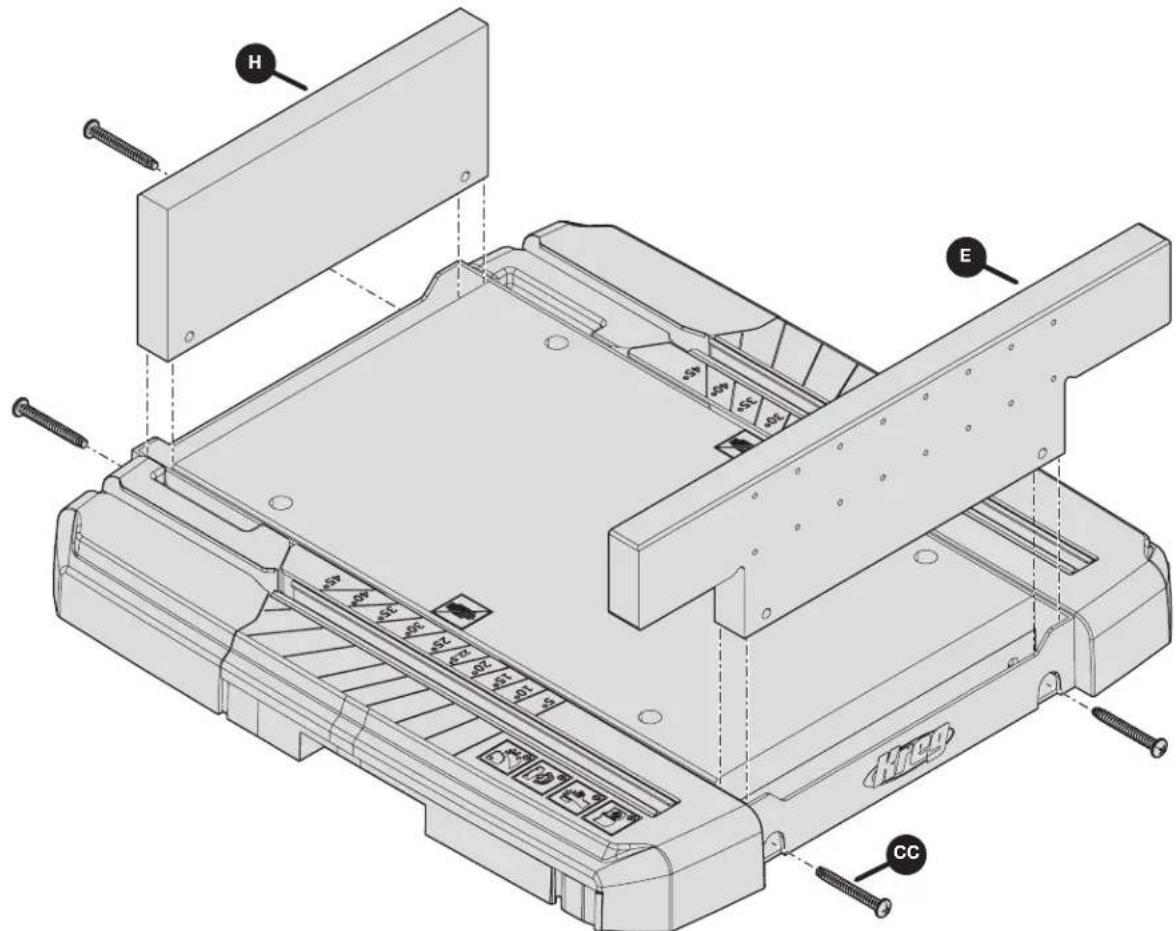
wings (D) crews (AA).2 Attach the Sure-Cut™ Back Board
a. Attach the front blade guard actuator board (H) and Sure-Cut™ back board (E) in place using four large screws (CC).
text_image
Technical diagram of a mechanical device with labeled parts H, E, and CC, showing internal components and mounting hardware.3 Attach the Guide Rails
WARNING Ensure rails are installed per the instructions below to keep your hand a safe distance from the rotating blade while cutting.
a. Ensure your saw blade is as centered as possible on the cutting surface. To accomplish this, set your fixed saw guide rail (B) on the front and back boards (H and E) on the side opposite of your blade (as shown).
b. Set your adjustable saw guide rail (C) on the front and back boards (H and E) to the width of your saw base plate.
c. Position the saw so that the blade is as centered as possible, and secure the fixed saw guide rail (B) to the corresponding holes in the front and back boards (H and E).
Note Depending on your saw type, this may result in the fixed rail being opposite the picture shown. The goal is to have your saw blade positioned as centered as much as possible in the cutting surface.
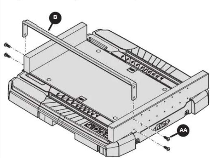
text_image
B AA
text_image
Technical diagram of a robotic device with labeled parts H, C, and E4 Attach the Rail Brackets
a. Set your saw aside and connect the adjustable saw guide rail brackets (BB) to the closest available holes on the front and back boards (H and E) using small screws (AA).
b. Tighten the top screws on the brackets (BB) to fix rail in place.
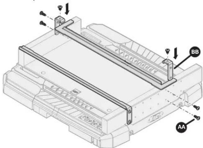
text_image
Technical diagram of a mechanical assembly with labeled components AA and BB, showing structural connections and mounting points.5 Attach the Fence and Clamps
a. If needed, slide the adjustable fence (G) and/or material hold-down clamps (F) into place on the material support wings (D).
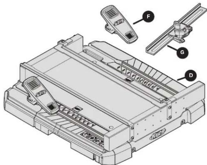
text_image
Technical diagram of a printer with labeled parts including front panel, side panel, and internal componentsOperation
WARNING Always make sure the Crosscut Station is secured to prevent movement while cutting.
Use the procedures in this section to begin using your Crosscut Station. The following examples show placement for a left blade saw.
Sure-Grip™ feet help to hold Crosscut Station in place while cutting. If a stronger hold is needed, you can affix the station to your work bench using two screws (not provided) and attaching through the holes in the side tracks, as shown by the arrows on the right.
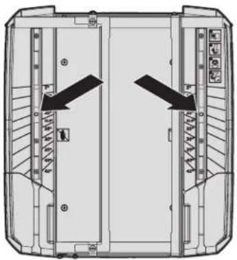
natural_image
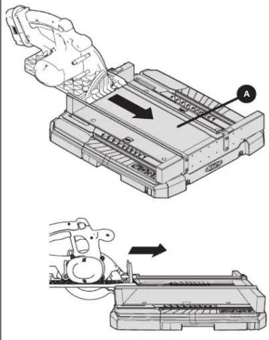
Top-down schematic of a mechanical or electrical component with directional arrows indicating flow or movement (no text or symbols present)Make your Kerf Line Cut
a. Before you make your kerf line, set the saw cut depth to 2" (just enough to score the bottom cut surface of the cutting base (A)).
b. Align the base of your saw to the rails behind the front blade guard actuator board (H).
c. Start your saw, and while keeping your saw flat to the guide rails, allow the front blade guard actuator board (H) to engage the blade guard while making a cut through it.
WARNING Do not try to lower the saw into the cut by using one hand to open the blade guard. Doing so could result in a saw kick back and serious injury.
ATTENTION Stop the saw and allow the blade to come to a stop once the center of the saw blade has cut through the Sure-Cut™ back board (E). Pushing well beyond the rails can cause a widening of your kerf line (1) and could affect your cut accuracy. See the images below for the proper stopping point as noted by the X symbol.
natural_image
Technical illustration showing a mechanical assembly with a hand operating a component and a close-up of the device's internal structure (no text or symbols present)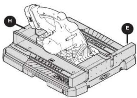
natural_image
Technical line drawing of a mechanical device with labeled components H and E (no text or symbols beyond labels)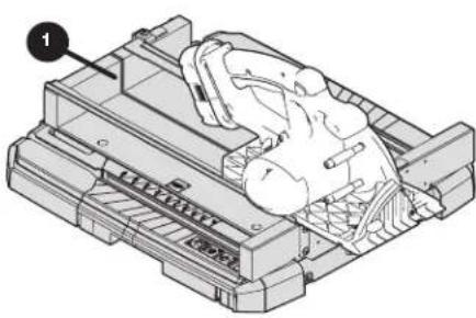
natural_image
Technical illustration of a mechanical assembly with no visible text or symbols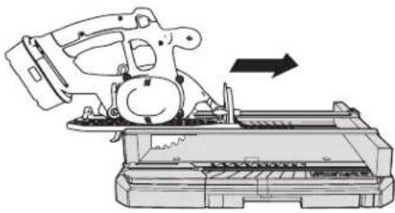
natural_image
Technical line drawing of a mechanical device with an arrow indicating direction (no text or symbols present)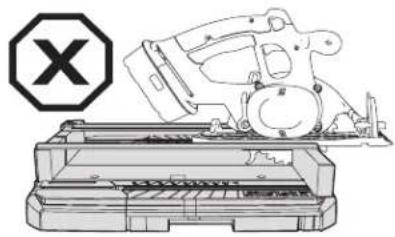
natural_image
Technical line drawing of a mechanical assembly with a cross symbol (no text or labels)Make a 90^ Cut
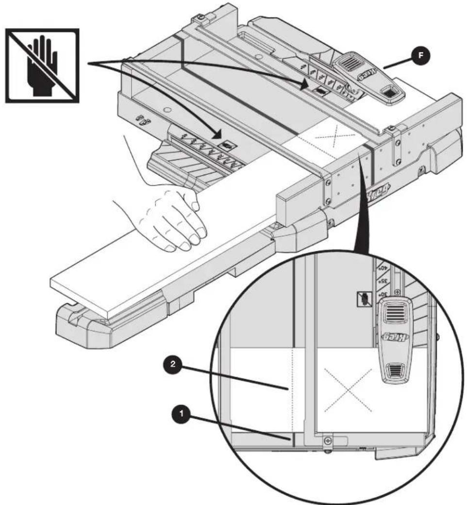
a. Mark your workpiece to the desired length (2).
b. Align the mark (2) with one edge of the saw kerf line (1), making sure that the workpiece is aligned to the blade so the blade will cut through the cutoff (waste) portion of the board (marked with an X in the illustration), and not through the side of the workpiece you want to keep.
c. Use the clamps (F) to help hold the workpiece on either side of the rails. In addition, use your hands to hold your workpiece outside of the cutting surface.
WARNING Do not reach behind the saw blade or the fence with either hand to hold down or support the workpiece, remove wood scraps, or for any other reason while cutting. The spinning saw blade may be so close to your hand that you may be seriously injured.
d. Align the front of your saw base to the rails and start the saw. Move the saw through the cut until you have cut entirely through your workpiece (center of the blade at the Sure-Cut™ back board).
e. Stop the saw and release the trigger while the saw is still on the rails. Once the motor has stopped, lift your saw and remove the workpiece and cutoff piece from the cutting station. This step keeps your kerf line true to your saw.
WARNING Do not cut pieces that are too small to be securely held or clamped.
WARNING Always secure the workpiece with a firm grip ensuring your hand stays outside of the cutting area as designated by the symbol.
text_image
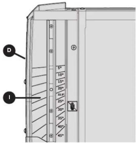
Technical diagram of a printer with labeled parts and an inset showing internal components, including hand and device views.Cut Different Angles
ATTENTION The width of the board you will be able to cut will vary depending on your saw and where you position the fence.
ATTENTION If you are not cutting the angle on the end of the board, cut to length at 90° before cutting the angle.
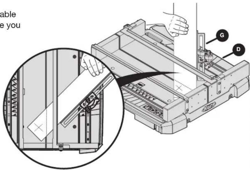
a. Position the front of the adjustable fence (G) to the desired angle line on the material support wings (D) on either side of the cutting station and tighten in place.
WARNING Position the end of the workpiece away from the Sure-Cut™ back board to avoid binding of the blade and kickback.
b. Tighten the fence in place and then follow the steps and precautions in Make a 90° Cut for making the cut.
text_image
able e you G D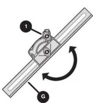
text_image
1 G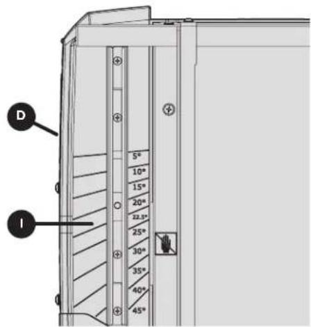
text_image
D I 5° 10° 15° 20° 22.5° 25° 30° 35° 40° 45°Cut Long Workpieces
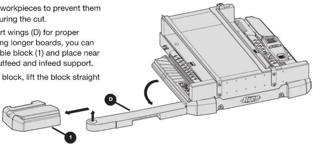
WARNING Support long workpieces to prevent them from sagging or shifting during the cut.
Extend the material support wings (D) for proper support for the cut. If cutting longer boards, you can easily remove the detachable block (1) and place near the end of the board for outfeed and infeed support.
To remove the detachable block, lift the block straight up from the support wing.
text_image
workpieces to prevent them uring the cut. rt wings (D) for proper ng longer boards, you can ble block (1) and place near utfeed and infeed support. block, lift the block straightCare and Cleaning
Keep dust and debris clear of all surfaces, including under the Crosscut Station and all Sure-Grip™ surfaces.
Troubleshooting
If accuracy of cuts is affected by misuse or improperly tightened parts, please contact our Customer Experience Team for assistance in replacement of cutting surfaces.

text_image
Kreg®EXPLORE. BUILD. SHARE.
We're makers just like you.
That's why we love to see what you're working on.
Share with the community and get inspired!
madewithKreg
Get free plans, project resources, and more. kregtool.com and buildsomething.com
GUIDE D'UTILISATEUR

text_image
Kreg®natural_image
Technical line drawing of a mechanical assembly with no visible text or symbolstext_image
Exploded view diagram of a device with labeled parts including chassis, chassis unit, and accessoriestext_image
Technical diagram of a printer internal structure with labeled parts H, E, and CCtext_image
Technical diagram of a robotic arm with labeled parts H, C, and E4 Fixez les supports de rail
text_image
Technical diagram of a mechanical assembly with labeled components AA and BB, showing structural connections and mounting points.text_image
Technical diagram of a mechanical device with labeled parts F, G, and D, showing internal components and assembly.Fonctionnement
natural_image
Top-down schematic of a vehicle front view showing structural components and directional arrows (no text or labels)text_image
Technical diagram showing mechanical assembly with labeled component A and directional arrows indicating motion or movement.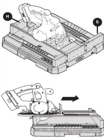
text_image
Technical diagram showing mechanical assembly steps with labeled components H and E, including a magnified view of the device's internal structure.
natural_image
Technical line drawing of a mechanical assembly with no visible text or symbolstext_image
Technical diagram of a printer with labeled parts and instructional annotations in Chinesenatural_image
Technical line drawing of a mechanical assembly with no visible text or symbolstext_image
Exploded view diagram of a mechanical device with labeled parts from A to Htext_image
Technical diagram of a mechanical assembly with labeled parts H, C, and Etext_image
Technical diagram of a mechanical assembly with labeled components AA and BB, showing structural connections and mounting points.text_image
Technical diagram of a printer or printer assembly with labeled parts D, G, and FFuncionamiento
natural_image
Top-down schematic of a vehicle front view showing structural components and directional arrows (no text or labels)text_image
Technical diagram showing mechanical assembly with labeled component A and directional arrows indicating motion or movement.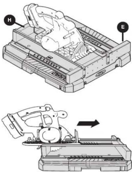
text_image
Technical diagram showing mechanical assembly with labeled parts H and E, including a magnified view of the device's internal structure.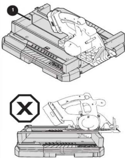
natural_image
Technical line drawing of a mechanical assembly with a labeled component (no text or symbols present)text_image
Technical diagram of a device with labeled parts and a prohibition symbol, showing hand positioning and internal components.natural_image
Technical line drawing of a mechanical assembly with no visible text or symbolsAVERTISSEMENT
text_image
Exploded view diagram of a device with labeled parts including chassis, chassis unit, and accessoriestext_image
Technical diagram of a printer internal structure with labeled parts H, E, and CCtext_image
Technical diagram of a mechanical assembly with labeled components H, C, and E4 Fixation des supports de rail
text_image
Technical diagram of a mechanical assembly with labeled components AA and BB, showing structural components and directional arrows.text_image
Technical diagram of a printer or printer assembly with labeled parts D, F, and GUtilisation
natural_image
Technical diagram of a mechanical or electrical component with directional arrows indicating movement or flow (no text or symbols present)natural_image
Technical illustration of a mechanical assembly with two views showing internal components and directional arrows (no text or symbols)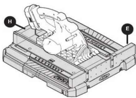
natural_image
Technical line drawing of a mechanical device with labeled parts H and E (no text or symbols beyond labels)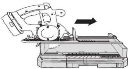
natural_image
Technical line drawing of a mechanical device with an arrow indicating motion (no text or symbols present)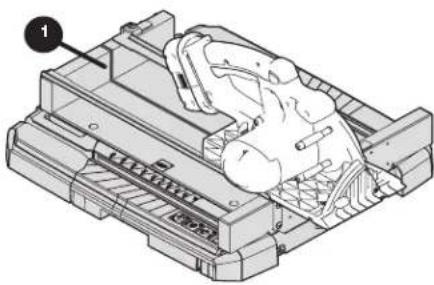
natural_image
Technical illustration of a mechanical assembly with a numbered component (no text or symbols visible)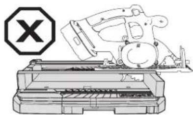
natural_image
Illustration of a mechanical device with a cross symbol (no text or labels present)text_image
Technical diagram of a printer with labeled parts and instructional annotations in Chinesetext_image
1 G D 5° 10° 15° 20° 22.5° 25° 30° 35° 40° 45° Inatural_image
Technical line drawing of a mechanical assembly with no visible text or symbolstext_image
Exploded view diagram of a device with labeled parts including chassis, chassis unit, and accessoriestext_image
Technical diagram of a printer internal structure with labeled parts H, E, and CCtext_image
Technical diagram of a mechanical assembly with labeled parts H, C, and Etext_image
Technical diagram of a mechanical assembly with labeled components AA and BB, showing structural connections and mounting points.text_image
Technical diagram of a mechanical device with labeled parts F, G, and D, showing internal components and assembly.Funcionamiento
natural_image
Top-down schematic of a vehicle or container with directional arrows indicating movement or flow (no text or symbols present)text_image
Technical diagram showing mechanical assembly with labeled component A and directional arrows indicating motion or movement.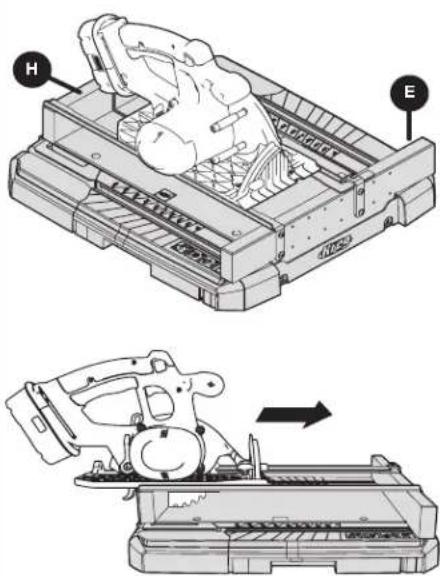
text_image
Technical diagram showing mechanical assembly steps with labeled components H and E, including a magnified view of the device's internal structure.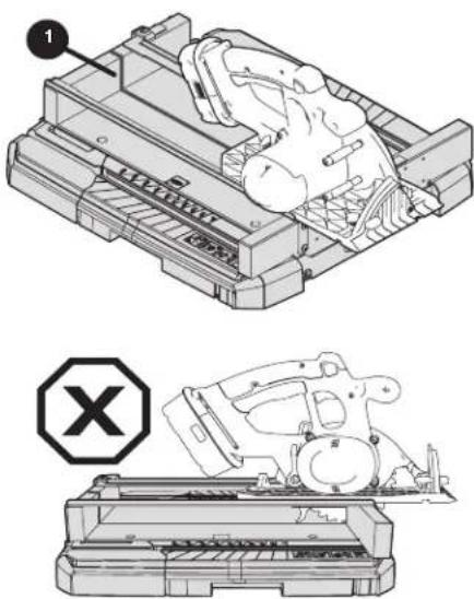
natural_image
Technical line drawing of a mechanical device with a labeled component and a warning symbol (no text or symbols present)text_image
Technical diagram of a device with labeled parts and a prohibition symbol, showing hand positioning and internal components.natural_image
Technical line drawing of a mechanical assembly with no visible text or symbolstext_image
Exploded view diagram of a device with labeled parts from A to Htext_image
Technical diagram of a printer internal structure with labeled parts H, E, and CCtext_image
Technical diagram of a mechanical assembly with labeled components A and B, showing structural layout and alignment indicators.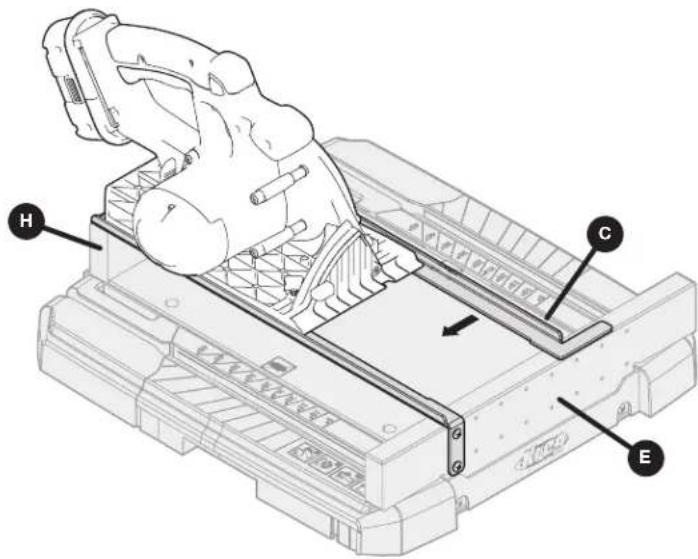
text_image
Technical diagram of a robotic arm assembly with labeled parts H, C, and Etext_image
Technical diagram of a mechanical assembly with labeled components AA and BB, showing structural connections and mounting points.text_image
Technical diagram of a mechanical device with labeled parts F, G, and D, showing internal components and assembly.Betrieb
natural_image
Top-down schematic of a vehicle front view showing internal compartments and directional arrows (no text or symbols)text_image
Technical diagram showing mechanical assembly with labeled component A and a close-up view of the device's internal structure.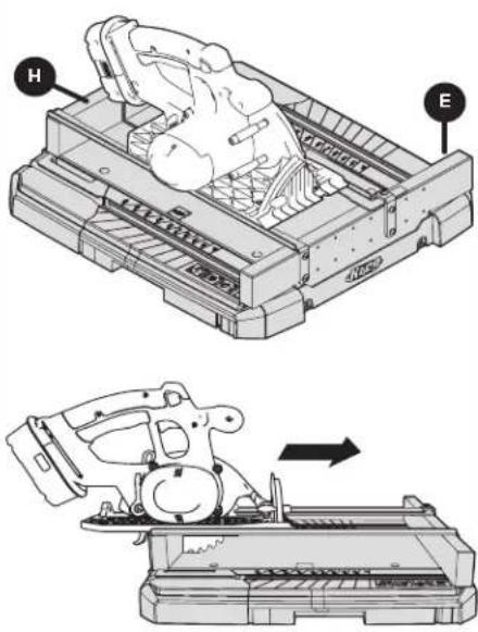
text_image
Technical diagram showing a mechanical device with labeled parts H and E, including a magnified view of the component.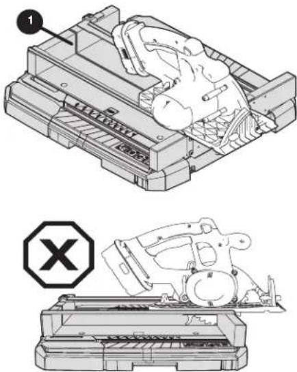
natural_image
Technical illustration of a mechanical assembly with two views: top shows a component being processed, bottom shows a device with a warning symbol (no text or labels present)text_image
Technical diagram illustrating a hand operating a device with labeled parts and a magnified inset showing internal components.text_image
Technical diagram showing a mechanical assembly with labeled parts G and D, including a magnified inset view of a component being inserted.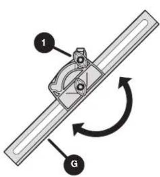
text_image
1 G