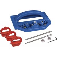
Straight Edge Guide - Saw Kreg - Free user manual and instructions
Find the device manual for free Straight Edge Guide Kreg in PDF.
| Product Type | Straight Edge Guide for Saws |
| Brand | Kreg |
| Compatible Models | KMA4500, KMA4500-E, KMA4600, KMA4600-E, KMA4700, KMA4700-E |
| Usage | Circular saw, jigsaw, router |
| Guide rail length (base model) | 71 cm (28 in) |
| Extension length | 61 cm (24 in) |
| Maximum length (XL model) | Varies based on number of sections assembled |
| Clamping system | Adjustable GripMaxx™ clamps with non-slip pads |
| Cut line indicators | Reversible arms with adjustable stops (knurled screw and nut) |
| Rail material | Extruded aluminum |
| Approximate weight (base kit) | 2.3 kg |
| Tools included | Hex key, set screws, knurled screws, nuts, handle bolt, handle nut |
| Tools required (not included) | #3 Phillips screwdriver, level or straightedge, pencil |
| Assembly | Upper and lower connection bars, secured with set screws |
| Calibration | Aligning indicator arms according to saw blade offset |
| Operation | Measure and mark material, position guide, clamp, cut along rail |
| Maintenance | Wipe pads, blow sawdust from rails, store hung |
| Safety | Read and follow power tool manufacturer instructions, wear PPE, avoid dangerous hand positions |
| Troubleshooting | Rail adjustment, recalibration, pad cleaning |
| Support | Technical support at 1-800-447-8638 or technicalsupport@kregtool.com |
Frequently Asked Questions - Straight Edge Guide Kreg
User questions about Straight Edge Guide Kreg
0 question about this device. Answer the ones you know or ask your own.
Ask a new question about this device
Download the instructions for your Saw in PDF format for free! Find your manual Straight Edge Guide - Kreg and take your electronic device back in hand. On this page are published all the documents necessary for the use of your device. Straight Edge Guide by Kreg.
USER MANUAL Straight Edge Guide Kreg
Manual applies to Item #
KMA4500 and KMA4500-E (Straight Edge Guide),
KMA4600 and KMA4600-E (Straight Edge Guide Extension),
KMA4700 and KMA4700-E (Straight Edge Guide XL)
natural_image
Technical line drawing of a long mechanical support or beam assembly with mounting brackets and a central plate (no text or symbols)WARNING Every user must read and follow instructions and safety precautions in this manual.
Failure to do so could result in serious injury. Save manual for future reference.
We're here to help.
We want you to have an exceptional project building experience.
If you have questions or need support, please get in touch.
1-800-447-8638 | technicalsupport@kregtool.com
Tell us about your experience.
Your opinion counts. And we're always looking for ways to improve.
Share your feedback so we can keep growing and innovating for you.
www.kregtool.com/feedback
| English | 2 |
| French (N. America) | 17 |
| Spanish (N. America) | 33 |
| French | 49 |
| Spanish | 65 |
| German | 81 |
Table of Contents
Safety Precautions .....2
Pre-Assembly....3
Recommended Tools/Materials (Not Included)....3 Hardware/Tools Included....3 Product Description....4
Assembly 5
Calibration. 8
Operation 11
Trim Router Calibration ..... 14
Trim Router Operation ..... 14
Care and Maintenance ..... 14
Troubleshooting. 15
Assembly 15
Set Up and Operation. ..... 15
Safety Precautions
WARNING Before using a power tool with this product, read and follow the tool manufacturer's instructions and safety precautions in addition to the safety precautions below to reduce risk of serious injury from hazards such as fire, electric shock, or moving the blades/bits.
- Follow your power tool manufacturer's instructions and safety precautions.
■ Always wear personal protective equipment required by the power tool manufacturer.
■ Do not allow familiarity gained from frequent use of your tools to replace safe work practices. A moment of carelessness is sufficient to cause severe injury.
■ Avoid awkward hand positions where a sudden slip could cause contact with the blade or cutting tool.
WARNING Do not operate this tool or any machinery while under the influence of drugs, alcohol, or medications.
WARNING This product can expose you to chemicals including Carbon 1333-86-4 and other chemicals, which are known to the State of California to cause cancer and reproductive harm. For more information go to www.P65Warnings.ca.gov.
The labels on the guide rail may include these symbols:
Be cautious of potential pinch point.

Wear proper eye, ear, and respiratory protection.

Keep hands and body away from and to the side of the blade. Contact with blade will result in serious injury.

Read the instructions.
Pre-Assembly
Review this section before you begin. Ensure you have all tools and materials on hand. Compare the package with the items listed in the Hardware Included and Product Description sections. Ensure you have a clean, flat area for joining the guide rails. If any item appears missing or lost, do not use this product. Contact Technical Support or return product to place of purchase.
Recommended Tools/Materials (Not Included)
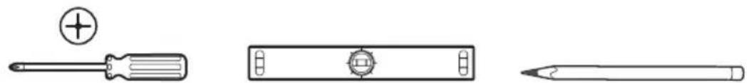
natural_image
Three technical line drawings of screwdriver, a cylindrical tool, and a pencil (no text or symbols)3 Phillips Screwdriver Straight Edge or Level Pencil
Hardware/Tools Included
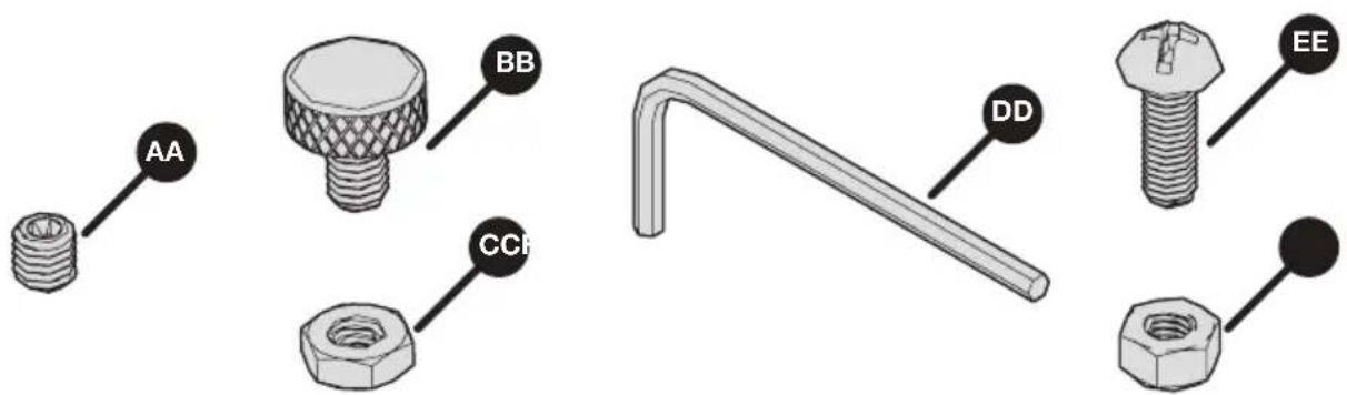
text_image
AA BB CCH DD EE| Straight Edge Guide Straight Edge Guide Extension Straight Edge Guide XL | ||
| AA - Set screws x 8 AA - Set | screws x 8 AA - Set screws x 24 | |
| BB - Outline indicator stop thumb screws x 2 | n/a | BB - Outline indicator stop thumb screws x 2 |
| CC - Outline indicator stop nuts x 2 | n/a | CC - Outline indicator stop nuts x 2 |
| DD - Hex wrench x 1 n/a DD | - Hex wrench x 1 | |
| EE - Handle bolt x 1 n/a EE - | Handle bolt x 1 | |
| FF - Handle nut x 1 n/a FF - | Handle nut x 1 | |
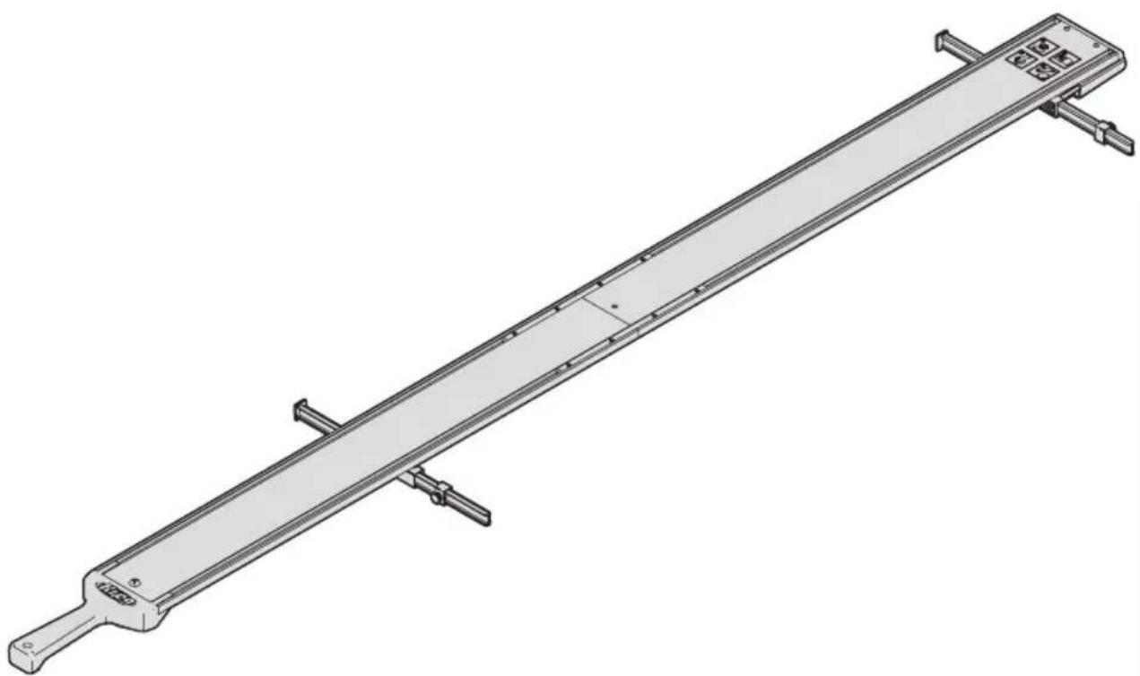
Product Description
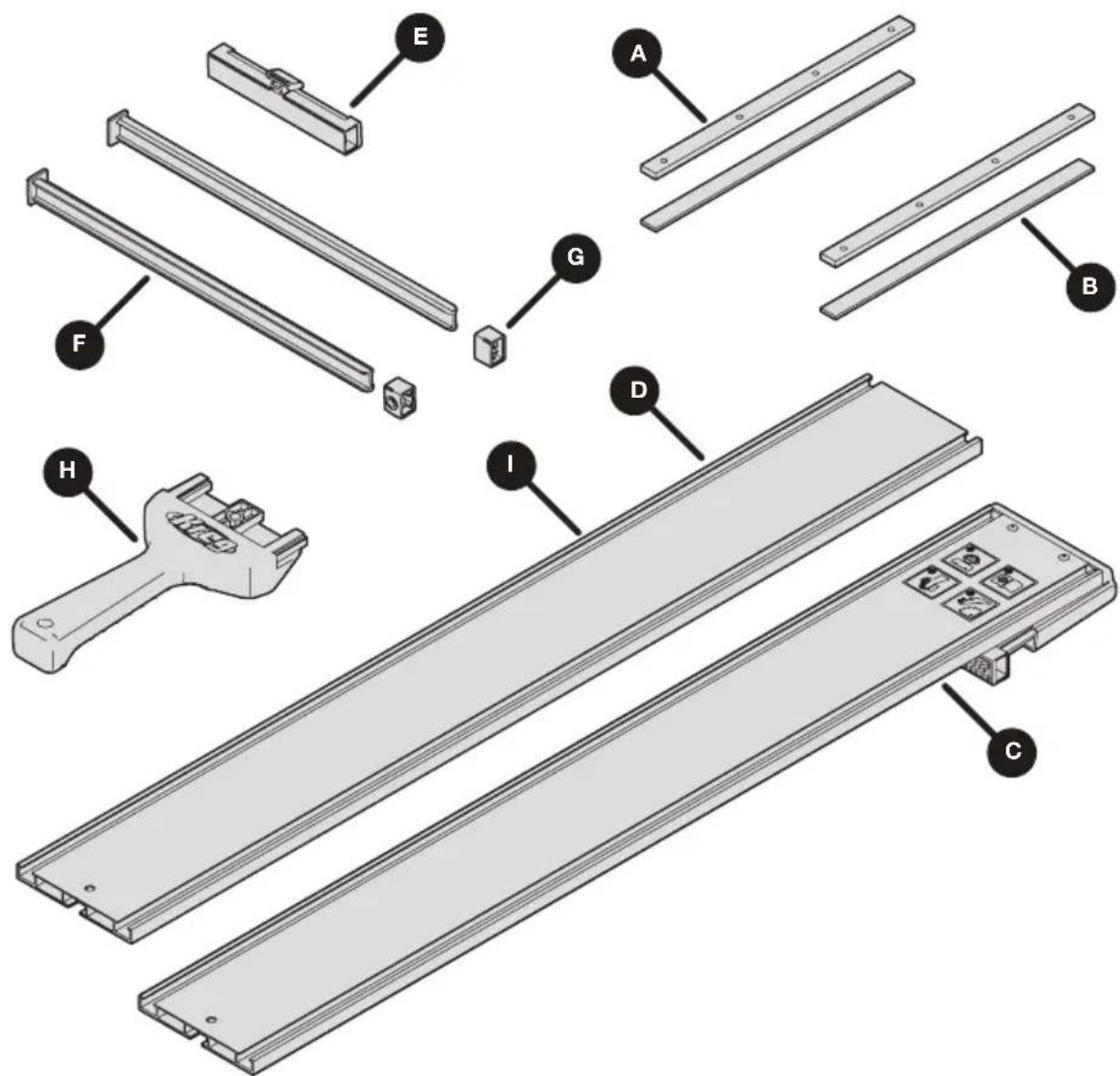
text_image
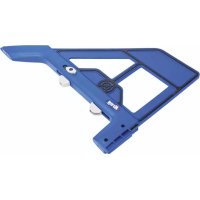
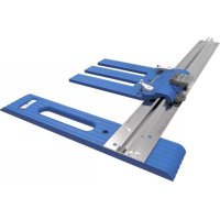
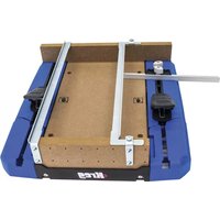
Exploded view diagram of a mechanical assembly with labeled parts including tool, bracket, and base plate| Straight Edge Guide Straight Edge Guide Extension Straight Edge Guide XL | ||
| A - Upper connector bars x 2 | A - Upper connector bars (preinstalled) x 2 | A - Upper connector bars x 6 |
| B - Lower connector bars x 2 | B - Lower connector bars (preinstalled) x 2 | B - Lower connector bars x 6 |
| C - Guide rail with GripMaxxTM clamp x 1 | n/a | C - Guide rail with GripMaxxTM clamp x 1 |
| D - Guide rail (28") x 1 n/a D | - Guide rail (28") x 1 | |
| E - Adjustable GripMaxxTM clamp x 1 | n/a | E - Adjustable GripMaxxTM clamp x 1 |
| F - Cutline indicator arms x 2 | n/a F - Cutline indicator arms x 2 | |
| G - Cutline indicator stops x 2 | n/a G - Cutline indicator stops x 2 | |
| H - Handle x 1 n/a H - Handle x 1 | ||
| n/a I - Guide rail extension (24") x 1 | I - Guide rail extension (24") x 2 | |
Assembly
1 Prepare the Upper Connector Bars
a. Thread all of the set screws (AA) into the upper connector bars (A).
b. Use the hex wrench (DD) to thread into place.
text_image
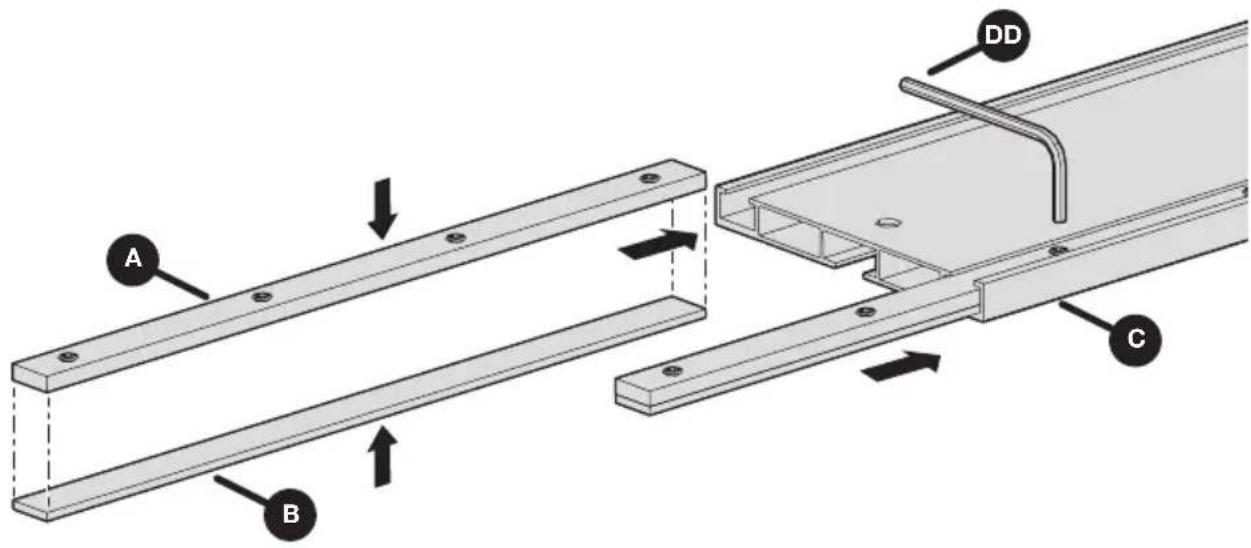
DD AA A2 Assemble the Connector Bars
a. Place an upper connector bar (A) over a lower connector bar (B) and slide this assembly into the channel of the guide rail with GripMaxx™ clamp (C), leaving about half of the connector bar assembly out of the channel.
b. Repeat for the other channel of the guide rail with GripMaxx ^TM clamp (C).
c. Partially snug the screws in the connector bars using the hex wrench (DD). This ensures the connector bars fit snugly into place in the channels.
ATTENTION Do not fully tighten the set screws. This will occur in step 3.
text_image
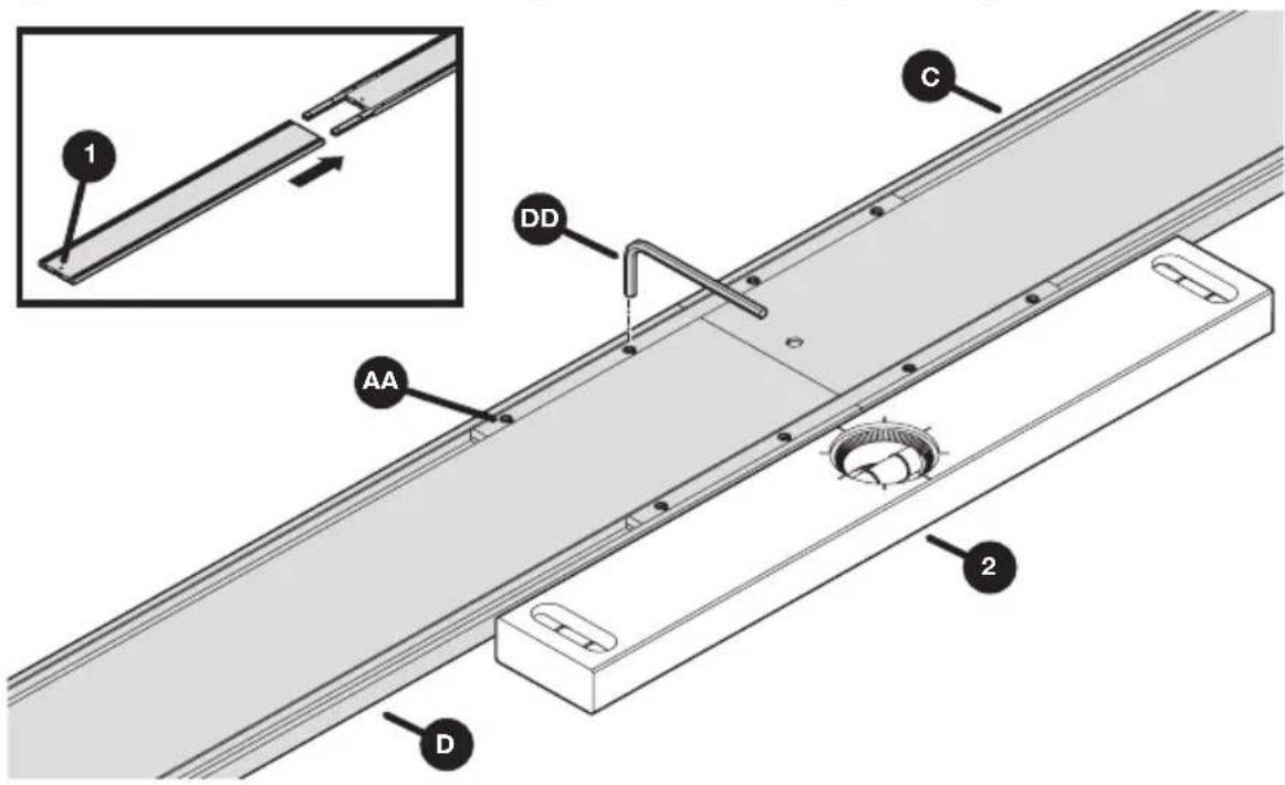
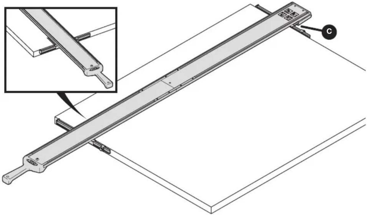
A B C DD3 Attach the Guide Rails
a. Slide the guide rail (D) onto the connector bars, ensuring that the hole on the guide rail (1) is furthest away from the connector bars.
b. Use a level (2) or straightedge to ensure the connected guide rails are aligned properly. Fully tighten the set screws (AA) in the connector bars on the guide rail (D) using the hex wrench (DD).
c. For Straight Edge Guide XL and Straight Edge Guide Extension: Repeat steps a and b until all guide rail sections are assembled.
ATTENTION Ensure set screws are tight but do not over-tighten to prevent marring the guide rail. The recommended tightness is 1/4 turn past snug.
text_image
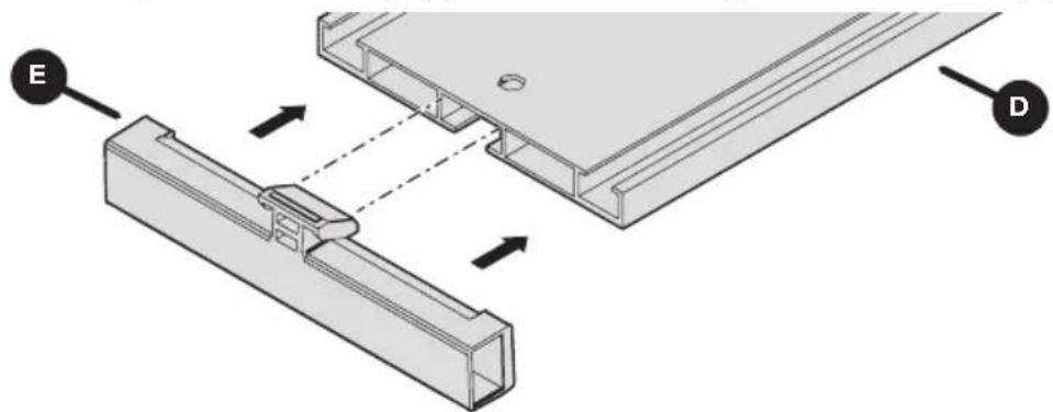
1 C DD AA 2 D4 Install the Adjustable GripMaxx ™ Clamp
a. Install the adjustable GripMaxx ^TM clamp (E) into the underside of the guide rail assembly (D).
b. Verify that the GripMaxx ^™ surface on the clamp faces the corresponding pad on the guide rail with GripMaxx ^™ clamp (C).
c. Tilt the adjustable GripMaxx ™ clamp (E) to slide into the guide rail assembly (D).
natural_image
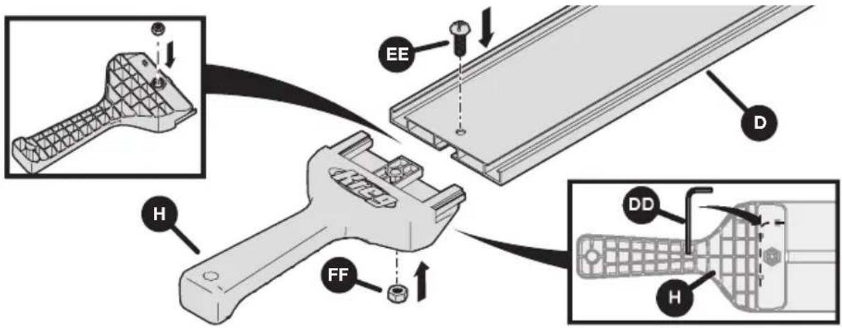
Technical diagram showing two mechanical components with labeled parts E and D, no readable text or symbols present.5 Install the Handle
a. Slide the handle (H) into the guide rail (D), ensuring the holes are aligned. Secure in place using the handle bolt (EE) and handle nut (FF).
b. Store the hex wrench (DD) in the clips on the underside of the handle.
text_image
Technical diagram illustrating the assembly of a handheld device with labeled parts (EE, D, H, FF) and internal components.6 Assemble the Outline Indicator Stops
a. Install a cutline indicator thumb screw (BB) and stop nut (CC) into a cutline indicator stop (G) as shown.
b. Repeat this process for both stops.

text_image
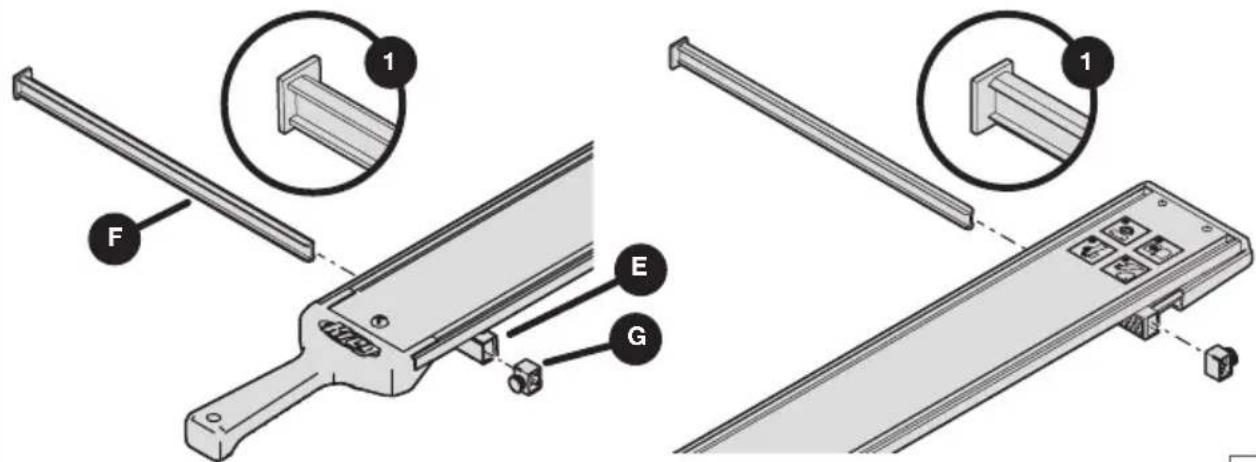
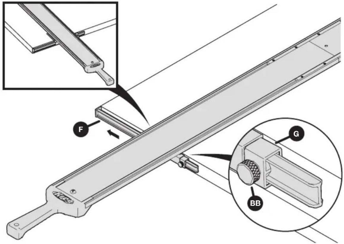
ps BB G CC7 Install the Indicator Arms
a. Slide a cutline indicator arm (F) into the adjustable GripMaxx ^TM clamp (E). Verify that the longer face (1) of the arm (F) is facing inward, as shown. Then install the cutline indicator stop (G) onto the other end of the arm (F).
b. Repeat to install the second cutline indicator arm on the guide rail with GripMaxx™ clamp (C), ensuring the longer face (1) points inward as well.
ATTENTION Cutline indicator arms are reversible for left- or right-bladed saws.
Refer to the calibration section of this manual.
text_image
Technical diagram showing assembly steps of a mechanical device with labeled components F, E, G and numbered parts 1Calibration
The indicator arms can be reversed based on left- or right-bladed saws. If your saw has a blade mounted on the left-hand side, install the indicator arms so the flat faces are positioned on the left side of the guide rail (as shown on previous page in step 7). If your saw has the blade mounted on the right-hand side, reverse the positioning so the flat face of each indicator arm is on the right side of the guide rail.
Note Indicator arms are long and will cover the distance from the blade to the baseplate edge of the most saws, between 1" – 5.5".
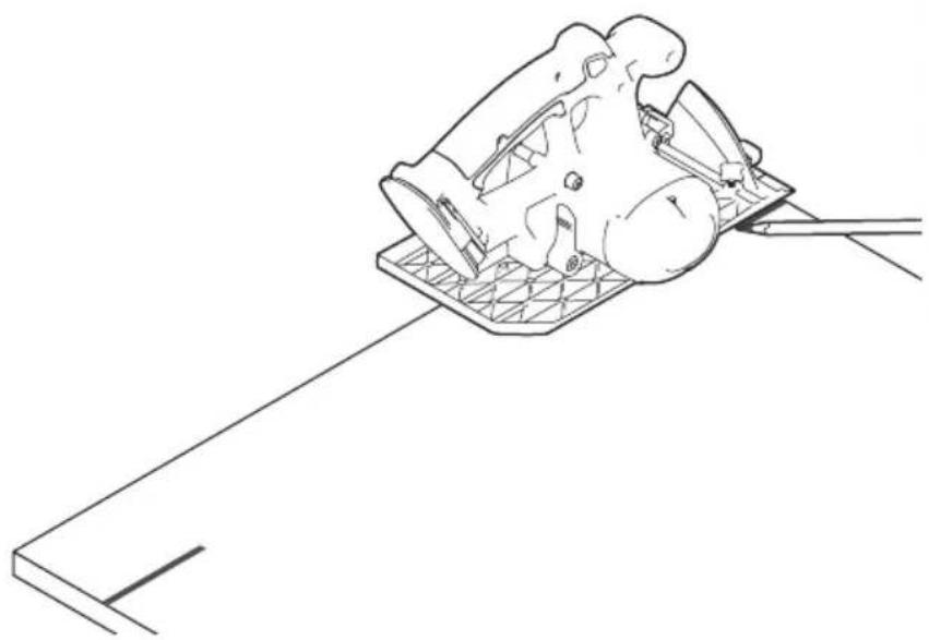
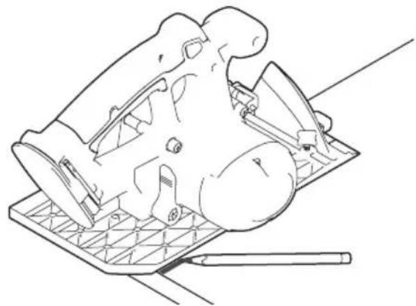
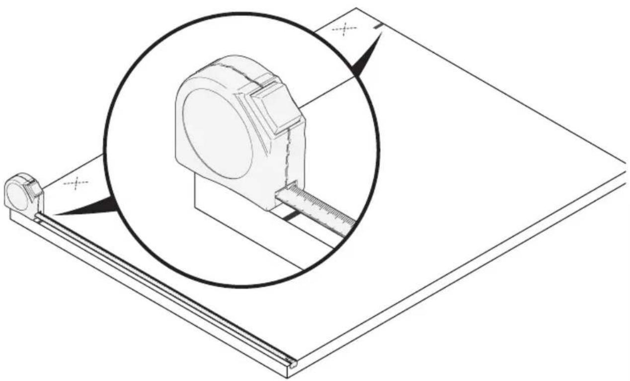
1 Position the Saw and Make Reference Marks
a. Ensure the saw is unplugged or the battery is removed. Set the blade depth of the saw to the material allowing for 1/8" more than material thickness. See your saw owner's manual for setting the depth.
b. Lift the blade guard to expose the blade, and position the saw on a piece of plywood so that the blade rests against the plywood edge.
c. Mark a line on the material of where the baseplate edge rests.
d. Repeat steps a - c at the far side of the material.
natural_image
Line drawing of a mechanical component with a base plate and tool, no text or symbols present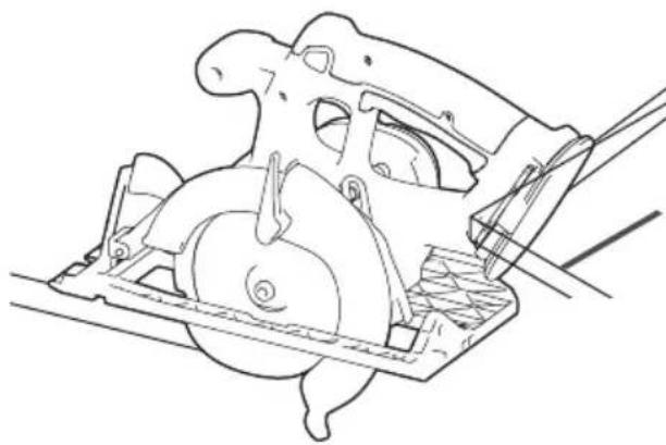
natural_image
Technical line drawing of a mechanical assembly with no visible text or symbols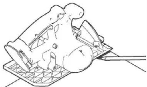
natural_image
Line drawing of a mechanical component with a base and handle, no text or symbols present2 Align the Guide Rail to the Marks
a. Place the guide rail on your material. Align and position the guide rail to your reference marks. Refer to Step 2 from the Operation section of the manual for proper alignment of the clamps to the material's edge.
Attention This is the only time that you will align the guide rail to your marks. After calibration, the cutline indicator arms will align to your measured marks as indicated in Step 2 of the Operation section of the manual.
b. Secure the guide rail in place. Refer to Step 3 from the Operation section of the manual to secure and clamp the guide.
natural_image
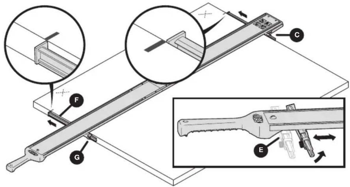
Technical line drawing of a mechanical lever system with an inset showing a close-up view of the component (no text or symbols present)3 Align the Outline Indicator Arms
a. On the cutline indicator stop (G), loosen the indicator thumb screw (BB) and slide the cutline indicator arm (F) out to align to the edge of the material. Slide the stop to the clamp edge and re-tighten the thumb screw (BB).
b. Repeat for the other cutline indicator arm to ensure you have aligned both arms to the edge of the material.
c. Remove the guide from the material after both cutline indicator arms have been aligned. Refer to Step 5 in the Operation section of the manual.
text_image
Technical diagram of a mechanical assembly with labeled parts F, G, and BB, showing structural components and assembly details.Note By setting the length of the cutline indicator arms, you have now accounted for the blade offset of your saw. This means the cutline indicator arms are calibrated to this specific saw. If you change tools, you may need to recalibrate the guide.
Note To calibrate for use with a jigsaw, repeat steps 1-3 above, but align the jigsaw blade with the edge of the material, instead.
Operation
WARNING Avoid awkward hand positions where a sudden slip could cause contact with the blade or bit.
This procedure applies to all models numbers covered in this manual and can be executed using a circular saw, jigsaw, or trim router.
1 Measure and Mark Your Material
Measure and mark on both sides of the material edge.
Note Make your mark lines at the edge of the material to your desired measurements. You will align the flat face of the cutline indicator arms to these marks moving forward.
Note Mark your cutoff (waste) portion of the board (marked with an X in the illustration below).
natural_image
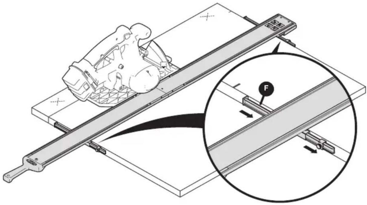
Technical line drawing of a mechanical assembly with a magnified inset showing a component detail (no text or symbols)2 Position the Guide Rail and Cutline Indicator Arms
a. Position the guide on your material with the guide rail with the GripMaxx ^TM clamp (C) flush to the far edge of the material. Tilt and slide the adjustable GripMaxx ^TM clamp (E) and slide it to align flush to the near edge of the material.
Note When the adjustable GripMaxx ^™ clamp (E) is tilted at an angle, it will travel and move in the guide rail. When it is tilted at 90° it will stop and not move.
b. Slide the cutline indicator arms (F) outward until the indicator stops (G) are against the clamps. Align the flat face of the arms to your measured marks.
Note Be sure to align both the near and far cutline indicator arms (F) to your measured marks.
text_image
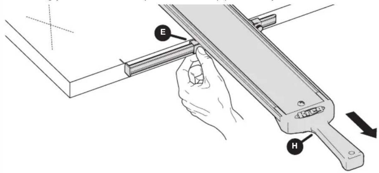
Technical diagram of a mechanical device with labeled parts (A, B, C, D, E, F) and directional arrows indicating movement or assembly.3 Clamp the Straight Edge Guide in Place on Your Material
With both indicator arms aligned to their marks, clamp the straight edge guide in place. Press against the middle of the adjustable GripMaxx™ clamp (E) with one hand while using your other hand to pull the handle (H) towards you.
text_image
E H4 Cut Your Material
a. Once the guide is set into place, slide the cut line indicator arms (F) away from the cut line.
b. Double-check the blade depth on your tool is correct, allowing 1/8" more than your material thickness (refer to the tool's owners manual for setting depth). Position the tool against the guide rail making sure the blade is not in contact with the material.
c. Start the tool and allow the blade to get up to full speed. Then begin the cut. Follow the guide rail, ensuring your tool hugs against the guide until the cut is complete.
natural_image
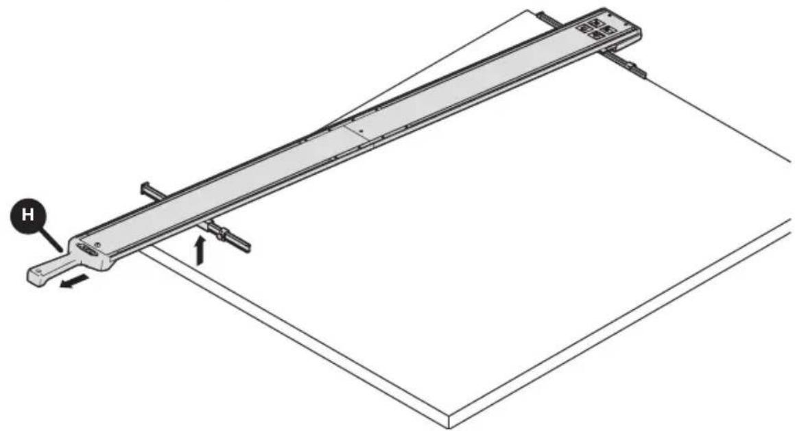
Technical illustration of a vehicle climbing a track with an inset showing force application (no text or symbols)5 Remove the Straight Edge Guide from the Material
Remove the straight edge guide from the material by placing one hand on the material and pulling back and up on the handle (H) to release.
natural_image
Technical line drawing of a mechanical lever system with labeled component H (no text or symbols beyond label)Tips and Tricks for Successful Operation
Ensure your guide rails lay flat on your material at all times. If necessary, remove saw dust from the material during cutting.
Ensure your material is not warped or bowed.
Trim Router Calibration
Calibration of a trim router will vary depending on the type and diameter of the bit you are using.
a. After you have chosen your bit and installed it in the tool, set the router on the material and position the bit against the edge of the material. Ensure that the cutting edge of the bit is positioned properly against the material edge. Make a mark at the edge of the base plate of the router. Do this on both the near and far side of the material.
b. Follow steps 2 and 3 from the saw calibration to align the bit offset and cut line indicator arm.
Trim Router Operation
The Straight Edge Guide works great for dado and rabbet cuts. Be sure you have set the correct depth of the bit you have chosen. Follow the same steps of the saw operation for use with your router.
Care and Maintenance
Keep sheet goods and material clear of wood chips and excessive dust.
Wipe clamp pads clear of dust to prevent the clamp from moving during use.
Clean the clamp pads and blow out sawdust in the guide rails prior to storage.
When storing, hang the guide rail assembly by the hang-hole in the handle.
You can also hang the rails by breaking down the guide rail sections and utilizing the hole in each guide rail section.
It is recommended that you leave the connector bars installed in the guide rail/guide rail extension sections to ensure they are not lost.
Troubleshooting
Assembly
| Problem Solution | |
| The guide rails do not connect snugly. | Ensure the top and base plate connectors with set screws are secured tight. |
| The rails are misaligned. Use a level or straightedge to align. | |
Set Up and Operation
| Problem Solution | |
| The handle is too far away to clamp to smaller/narrow material. | Remove a section of guide rail and use only one section. Reinstall the handle. |
| The guide rail is not long enough for larger pieces. | Purchase the Extension or XL version of this product. |
| The guide rails slips and the clamp does not hold to the material snugly. | Ensure the guide rail sits flat and that the cutline indicator arms sit flat to the material. When setting the clamp do not pull upwards. |
| The cut is not accurate to the line. Recalibrate the tool. | |
| The distance of the indicator arm does not reach to the blade for offset. | Reinstall indicator arm facing the other way in clamp pads and recalibrate. |
| The material warps under the clamp pressure causing the guide not to sit flat. | It is recommended to fully support the workpiece and cutoff with 2x4s or with 2"-thick (50 mm) rigid foam insulation laid flat on the floor. |
| The guide will not sit flat on the material because the clamp pads touch the ground. | Clamp pads are designed for material thickness 3/4" or greater for on the ground cutting. For thinner materials such as 1/2" or less, elevate the workpiece to ensure the pads are off the ground. |
| The guide moves or shifts during use. | Ensure you have applied adequate clamping pressure when positioning the tool. |
| Routing dadoes and rabbets do not align to my measurements. | Recalibrate the indicator arms considering the bit type and diameter. |
| The saw gets hard to push, burning occurs, or the saw walks away from the guide. | The saw blade may not be square to the saw base plate. See the saw owner's manual. |
| The jigsaw vibrates the clamp loose. | Check to ensure oscillating mode on your jigsaw is turned off. |
| The clamp does not hold to the material. Check the material for square edges. | |

text_image
Kreg®EXPLORE. BUILD. SHARE.
We're makers just like you.
That's why we love to see what you're working on.
Share with the community and get inspired!
madewithKreg
Get free plans, project resources, and more. kregtool.com and buildsomething.com
GUIDE D'UTILISATEUR

text_image
Kreg®Guide de bord droit
natural_image
Technical line drawing of a long mechanical lever or support structure with mounting brackets and a central shaft (no text or symbols)AVERTISSEMENT
natural_image
Technical line drawings of three electrical components: screwdriver, sliding contactor, and pencil (no text or symbols)text_image
AA BB CCF DD EEtext_image
Exploded view diagram of a mechanical assembly with labeled parts including tool, bracket, and frame platetext_image
Technical diagram of a mechanical assembly with labeled components (1, 2, C, D, AA, DD) and an inset showing a detail view.4 Installez la pince ajustable GripMaxx™
natural_image
Technical diagram showing two mechanical components with directional arrows indicating assembly or movement (no text or symbols present)text_image
Technical diagram illustrating the assembly of a handheld device with labeled parts (H, FF, EE, D) and internal components.text_image
Technical diagram showing assembly steps of a mechanical device with labeled components F, E, G and numbered parts 1Calibration
natural_image
Technical line drawing of a mechanical assembly with no visible text or symbols
natural_image
Line drawing of a mechanical component with a grid base and pencil, no text or symbols present
natural_image
Technical line drawing of a mechanical component mounted on a base plate, with no visible text or symbols.natural_image
Technical line drawing of a mechanical lever assembly with an inset showing a close-up view of the component (no text or symbols present)text_image
Technical diagram of a mechanical assembly with labeled parts F, G, and BB, showing structural components and assembly details.natural_image
Technical line drawing of a mechanical assembly with a magnified inset showing a component (no text or symbols)text_image
Technical diagram of a mechanical device with labeled components and directional arrows indicating motion or assembly.text_image
Technical diagram showing a hand operating a mechanical tool with labeled parts E and H, indicating assembly or inspection.natural_image
Technical illustration of a vehicle chassis on an inclined conveyor belt with a magnified inset showing force application (no text or symbols)natural_image
Technical line drawing of a mechanical lever system with labeled component H (no text or symbols beyond label)natural_image
Technical line drawing of a long mechanical lever or support structure with mounting brackets and a central shaft (no text or symbols)ADVERTENCIA
natural_image
Technical line drawings of three electrical components: screwdriver, sliding contactor, and pencil (no text or symbols)text_image
AA BB CCH DD EEtext_image
Exploded view diagram of a mechanical assembly with labeled parts including a wrench, tool holder, and frame platetext_image
1 C DD AA 2 Dnatural_image
Technical diagram showing two mechanical components with directional arrows indicating assembly or movement (no text or symbols present)text_image
Technical diagram illustrating the assembly of a handheld device with labeled parts (H, FF, EE, D) and internal components.text_image
Technical diagram showing assembly steps of a mechanical device with labeled components F, E, G and numbered parts 1Calibración
natural_image
Line drawing of a mechanical component with a tool and grid base (no text or symbols)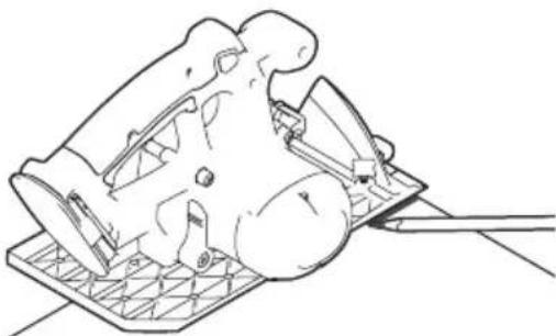
natural_image
Technical line drawing of a mechanical component with a base and clamped parts (no text or symbols)
natural_image
Technical line drawing of a mechanical assembly with no visible text or symbolsnatural_image
Technical line drawing of a mechanical lever assembly with an inset showing a close-up view of the component (no text or symbols present)text_image
Technical diagram of a mechanical assembly with labeled parts F, G, and BB, showing structural components and assembly details.natural_image
Technical line drawing of a mechanical assembly with a magnified inset showing a component (no text or symbols)text_image
Technical diagram of a mechanical device with labeled components and directional arrows indicating motion or assembly.text_image
Technical diagram showing a hand operating a mechanical tool with labeled parts E and H, indicating assembly or inspection.4 Corte del material
natural_image
Technical illustration of a vehicle chassis on an inclined conveyor belt with a magnified inset showing force application (no text or symbols)natural_image
Technical line drawing of a mechanical lever system with labeled component H (no text or symbols beyond label)natural_image
Technical line drawing of a long mechanical lever or support structure with mounting brackets and a central shaft (no text or symbols)AVERTISSEMENT
natural_image
Technical line drawings of three electrical components: screwdriver, sliding contactor, and pencil (no text or symbols)text_image
AA BB CCF DD EEtext_image
Exploded view diagram of a mechanical assembly with labeled parts including tool, bracket, and housingtext_image
1 C DD AA 2 Dnatural_image
Technical diagram showing two mechanical components with directional arrows indicating assembly or movement (no text or symbols present)text_image
Technical diagram of a handheld device with labeled parts including handle, switch, and keyboard, showing assembly steps.text_image
Technical diagram showing assembly steps of a mechanical device with labeled components F, E, and GCalibration
natural_image
Line drawing of a mechanical component with a base plate and tool, no text or symbols present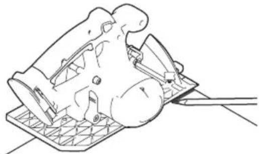
natural_image
Line drawing of a mechanical device with a base and handle, no text or symbols present
natural_image
Technical line drawing of a mechanical assembly with no visible text or symbolsnatural_image
Technical line drawing of a mechanical lever assembly with an inset showing a close-up view of the component (no text or symbols present)text_image
Technical diagram of a mechanical assembly with labeled parts F, G, and BB, showing structural components and assembly details.natural_image
Technical line drawing of a mechanical assembly with a magnified inset showing a component (no text or symbols)text_image
Technical diagram of a mechanical device with labeled components (A, B, C, D, E, F) and directional arrows indicating motion or assembly.natural_image
Technical illustration of a mechanical assembly with a magnified inset showing force application (no text or symbols)natural_image
Technical line drawing of a mechanical lever system with labeled component H (no text or symbols beyond label)natural_image
Technical line drawing of a long mechanical lever or support structure with mounting flanges and a central shaft (no text or symbols)ADVERTENCIA
text_image
AA BB CCH DD EEtext_image
Exploded view diagram of a mechanical assembly with labeled parts including a wrench, tool holder, and panel plate.text_image
1 C DD AA 2 D4 Instalar la abrazadera ajustable GripMaxx ™
natural_image
Technical diagram showing two mechanical components with directional arrows indicating assembly or movement (no text or symbols present)5 Instalar el mango
text_image
Technical diagram illustrating the assembly of a handheld device with labeled parts (EE, D, H, FF) and internal components.text_image
Technical diagram showing assembly steps of a mechanical device with labeled components F, E, and GCalibración
natural_image
Technical line drawing of a mechanical assembly with no visible text or symbols
natural_image
Line drawing of a mechanical component with a grid base and tool, no text or symbols present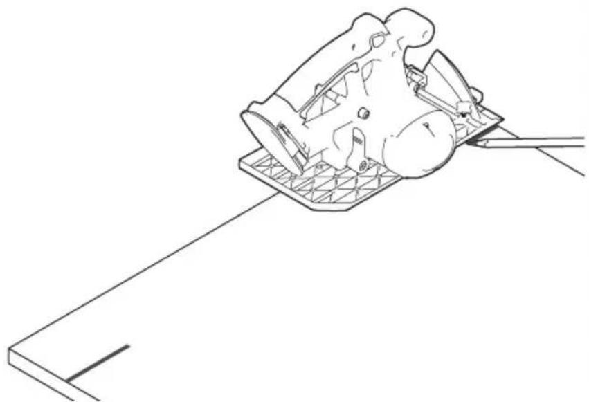
natural_image
Line drawing of a mechanical component with a rod extending from it, no text or symbols presentnatural_image
Technical line drawing of a mechanical lever system with an inset showing a close-up view of the component (no text or symbols present)text_image
Technical diagram of a mechanical assembly with labeled parts F, G, and BB, showing structural components and assembly details.natural_image
Technical line drawing of a mechanical assembly with a magnified inset showing a component (no text or symbols)text_image
Technical diagram illustrating a mechanical assembly with labeled components (A, B, C, D, E, F) and directional arrows indicating motion or movement.natural_image
Technical illustration of a mechanical assembly with a magnified inset showing force application (no text or symbols)natural_image
Technical line drawing of a mechanical lever system with labeled component H, showing motion path and support structure (no text or symbols beyond labels)natural_image
Technical line drawing of a long mechanical lever or support structure with mounting brackets and a central shaft (no text or symbols)text_image
AA BB CCH DD EEtext_image
Exploded view diagram of a mechanical assembly with labeled parts including a wrench, tool holder, and bracket components.text_image
Technical diagram of a mechanical assembly with labeled components including DD, AA, and D, alongside an inset showing a component labeled 1.4 Verstellbare GripMaxx ™-Klemme installieren
natural_image
Technical diagram showing two mechanical components with directional arrows indicating assembly or movement (no text or symbols present)5 Handgriff installieren
text_image
Technical diagram of a handheld device with labeled parts including handle, base, and control paneltext_image
Technical diagram showing assembly steps of a mechanical device with labeled components F, E, G and numbered parts 1Kalibrierung
natural_image
Technical line drawing of a mechanical assembly with no visible text or symbols
natural_image
Line drawing of a mechanical component with a base plate and tool, no text or symbols present