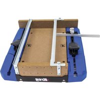
RipCut - Saw Kreg - Free user manual and instructions
Find the device manual for free RipCut Kreg in PDF.
| Product Type | Rip-Cut Circular Saw Guide |
| Brand | Kreg |
| Model | RipCut (KMA2685-INT) |
| Materials | Aluminum rail, reinforced plastic carriage, steel edge guide |
| Rail Dimensions | Approximately 610 mm (24 inches) long |
| Weight | Approximately 1.4 kg (3.1 lb) |
| Power Source | Works with circular saw (tool not included) |
| Maximum Cut | Approximately 610 mm (24 inches) width |
| Minimum Safe Cut | 25 mm (1 inch) |
| Saw Compatibility | Circular saws with flat or beveled base, left or right blade |
| Main Function | Precise rip cuts parallel to the workpiece edge |
| Other Functions | Adjustable edge guide for right/left hand, measuring cursor, positioning stop |
| Safety | Saw blade guard must operate freely; kickback prevention; stop before removal |
| Maintenance and Cleaning | Clean regularly, check alignment and screw tightness |
| Spare Parts and Repairability | Parts listed in the manual: edge guide, screws, rail, cursor, etc. |
| General Information | Use only with sharp blades; unplug saw before adjustments |
Frequently Asked Questions - RipCut Kreg
User questions about RipCut Kreg
0 question about this device. Answer the ones you know or ask your own.
Ask a new question about this device
Download the instructions for your Saw in PDF format for free! Find your manual RipCut - Kreg and take your electronic device back in hand. On this page are published all the documents necessary for the use of your device. RipCut by Kreg.
USER MANUAL RipCut Kreg
ITEM No. KMA2685-INT
text_image
Hip-Gut JOG-1/H
WARNING
When using electric tools, always follow the safety precautions below to reduce the risk of fire, electric shock. Read all of these instructions before attempting to operate this product. SAVE THESE INSTRUCTIONS.
1) Work area safety
a) Keep work area clean and well lit. Cluttered or dark areas invite accidents.
b) Don't use power tools in a dangerous environment. Don't use power tools in damp or wet locations, or expose them to rain.
c) Do not operate power tools in explosive atmospheres, such as in the presence of flammable liquids, gases or dust. Power tools create sparks that can ignite the fumes or dust.
d) Keep children and bystanders away while operating a power tool. Distractions can cause you to lose control.
e) Make your workshop childproof. Use padlocks or master switches, or remove starter keys.
2) Electrical safety
a) Earth electric tools. If the tool is equipped with a three-prong plug, it must only be plugged into an earthed three-hole electrical socket. If the proper socket is not available, have one installed by a qualified electrician. Never remove the third prong or modify the provided plug in any way.
b) Do not expose power tools to rain or wet conditions. Water entering a power tool increases the risk of electric shock.
c) Do not abuse the cord. Never use the cord for carrying, pulling or unplugging the power tool. Keep cord away from heat, oil, sharp edges and moving parts. Damaged or entangled cords increase the risk of electric shock.
d) Use a proper extension cord and make sure it is in good condition. When using an extension cord, make sure that you use one that is heavy enough to carry the current your power tool draws. An undersized cord causes a drop in line voltage resulting in loss of power and overheating. Table 1 shows the correct cord gauge to use depending on cord length and tool nameplate ampere rating. If in doubt, use the next heavier gauge. The smaller the gauge number, the heavier the cord.
e) When operating electric tools, avoid body contact with earthed surfaces such as pipes, radiators, kitchen hobs and refrigerators. Contact with an earthed surface increases the risk of electric shock.
3) Personal safety
a) Stay alert, watch what you are doing and use common sense when operating a power tool. Do not use a power tool while you are tired or under the influence of drugs, alcohol or medication. A moment of inattention while operating power tools can result in serious personal injury.
b) Always wear safety glasses. Everyday glasses are not safety glasses. Safety glasses have specially constructed lenses, frames and side shields.
c) Use safety equipment. Use a face or dust mask when the cutting operation is dusty. Safety equipment such as a dust mask, non-skid safety shoes, hard hat or hearing protection used for appropriate conditions reduces personal injuries.
d) Avoid accidental starting. Make sure the switch is in the off-position before plugging in. Carrying power tools with your finger on the switch or plugging in power tools that have the switch on invites accidents.
e) Remove any adjusting key or wrench before turning the power tool on. A wrench or a key left attached to a rotating part of the power tool can result in personal injury.
f) Do not overreach. Keep proper footing and balance at all times. This enables better control of the power tool in unexpected situations.
g) Secure workpieces. Use clamps or a vice to hold work when practical. This is safer than using your hand and it frees both hands to operate the tool.
h) Never stand on the machine. Serious injury can occur if the tool tips or if the cutting tool is unintentionally contacted.
i) Dress properly. Do not wear loose clothing or jewellery. Keep your hair, clothing and gloves away from moving parts. Loose clothes, jewellery or long hair can be caught in moving parts. Roll up long sleeves to the elbow. Wear protective hair covering to contain long hair.
j) If devices are provided for the connection of dust extraction and collection equipment, ensure these are connected and properly used. Use of these devices reduces dust-related hazards.
4) Power tool use and care
a) Keep guards in place and in working order.
b) Do not force the power tool. Use the correct power tool for your application. The correct power tool will do the job better and more safely at the rate for which it was designed.
c) Use the right tool. Don't force a tool or attachment to do a job for which it was not designed.
d) Do not use the power tool if the switch does not turn it on and off. Any power tool that cannot be controlled with the switch is dangerous and must be repaired.
e) Disconnect the plug from the power source and/or the battery pack from the power tool before making any adjustments, changing accessories or storing power tools. Such preventive safety measures reduce the risk of starting the power tool accidentally.
f) Never leave a tool running unattended. Turn power off. Do not leave the tool until it has come to a complete stop. g) Store idle power tools out of the reach of children and do not allow persons unfamiliar with the power tool and these instructions to operate the power tool. Power tools are dangerous in the hands of untrained users.
h) Maintain power tools. Check for misalignment or binding of moving parts, broken parts and any other condition that can affect power tool operation. If damaged, have the power tool repaired before use. Many accidents are caused by poorly maintained power tools.
i) Keep cutting tools sharp and clean. Properly maintained cutting tools with sharp cutting edges are less likely to bind and are easier to control.
j) Use the recommended speed for the cutting tool or accessory and workpiece material.
k) Only use parts and accessories recommended by the manufacturer. Consult the owner's manual for recommended accessories. Using improper accessories can cause personal injury.
I) Use the power tool, accessories and tool bits in accordance with these instructions and in the manner intended for the particular type of power tool, taking into account the working conditions and the work to be performed. Use of the power tool for operations different from those intended can result in a hazardous situation.
5) Service
a) Have your power tool serviced by a qualified repair person using only identical replacement parts. This ensures that the safety of the power tool is maintained.
6) SAFETY INSTRUCTIONS SPECIFIC TO USING THE RIP-CUT™
a) Before using the Rip-Cut ^™ , read, understand and follow the safety warnings and operation instructions included with this product and provided by your saw manufacturer. Keep all guards and safety devices in place.
b) Wear correct eye, ear and respiratory protection when operating your saw.
c) Use a sharp blade designed for the type of material you are cutting.
d) Always disconnect your saw from power before making adjustments to the saw or Rip-Cut ^™ .
General Safety Guidelines
e) Check the cursor alignment before you cut.
f) Ensure that the saw blade will not contact the edge guide during the cut.
g) Do not attempt a cut when any part of the Rip-Cut ^™ sled interferes with the operation of the saw blade guard.
h) Fully support both the workpiece and the cut-off piece to prevent binding and kickback.
i) Adjust the depth of cut so that the saw blade protrudes 18 " [3 mm] through the workpiece during the cut.
j) Keep your hands away from the saw blade during operation. Do not reach under the workpiece while cutting. k) Secure your workpiece to ensure that it doesn't move during the cut.
I) Do not use excessive force when cutting.
Maintain a steady and controlled pace.
m) Allow the saw blade to come to a complete stop before lifting the Rip-Cut from your workpiece.
n) Maintain your tools and accessories.
Check for misalignment or binding of moving parts, loose fasteners, broken parts and any other condition that may affect safe operation. If an unsafe condition is discovered, correct it before use.
7) Kickback
Kickback is a sudden reaction to a pinched, bound or misaligned saw blade, causing an uncontrolled saw to lift up and out of the workpiece towards the operator.
8) Causes of kickback
a) When the blade is pinched or bound tightly by the kerf closing in, the blade stalls and the motor reaction drives the unit rapidly back towards the operator.
b) If the blade becomes twisted or misaligned in the cut, the teeth at the back edge of the blade can dig into the top surface of the wood causing the blade to climb out of the kerf and propel the saw back towards the operator.
Preventing kickback
Kickback is the result of tool misuse and/or incorrect operating procedures or conditions and can be avoided by taking proper precautions.
a) Maintain a firm grip with both hands on the saw and position your body and arms to resist kickback forces. Kickback forces can be controlled by the operator if proper precautions are taken.
b) When the blade starts to bind, or when interrupting a cut for any reason, release the trigger and hold the saw motionless in the material until the blade comes to a complete stop. Never attempt to remove the saw from the work or pull the saw backwards while the blade is in motion. Investigate and take corrective actions to eliminate the cause of blade binding.
c) When restarting a saw in the workpiece, centre the saw blade in the kerf and check that the saw teeth are not engaged in the material. If the saw blade is binding, the blade may climb out of the workpiece and kick back as the saw is restarted. d) Support large panels to minimise the risk of blade pinching and kickback. Large panels tend to sag under their own weight. Supports must be placed under the panel on both sides of the cut: near the cut line and near the edge of the panel.
e) Do not use a dull or damaged blade. A dull or improperly sharpened blade produces a narrow kerf, causing excessive friction, blade binding and kickback.
f) Blade depth and bevel adjusting locks must be tight and secure before making a cut. If blade adjustment shifts while cutting, it may cause binding and kickback.
g) Use extra caution when making a plunge cut into existing walls, floors or other blind areas. The protruding blade may come into contact with unseen objects that can cause kickback.
Guidelines for extension cord use
Extension cords are only to be used for temporary purposes. They do not replace the need for installation of sockets and proper wiring where necessary.
In the workshop and on construction sites:
- Extension cords with an equipment earthing conductor must be used at all times.
- Extension cords must be protected from damage, and not run through doorways or windows where the doors or windows can close, causing damage to the cord.
- Extension cords must be a minimum of 16 AWG and be rated for the equipment in use.
- Extension cords must be periodically inspected to ensure that the insulation and conductivity of the wires are not compromised.
- Extension cords should not be run through water or allowed to have connections that may be exposed to accumulated water.
TABLE 1
| Nameplate Amperes @120 V | Extension Cord Length | |||||
| 25' 50' | 75' 100' | 150' 200' | ||||
| Recommended Wire Gauge | ||||||
| 0 -5 16 16 16 | 14 12 12 | |||||
| 5.1 - 8 16 16 14 | 12 10 NR | |||||
| 8.1 -12 14 14 12 | 10 NR NR | |||||
| 12.1 - 16 12 12 | NR NR NR | NR | ||||
NR – Not Recommended

WARNING:
This product can expose you to chemicals including Acrylonitrile
and other chemicals, which are known to the State of California to cause cancer and reproductive harm. For more information, go to www.P65Warnings.ca.gov.
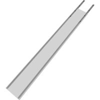
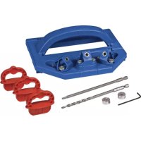
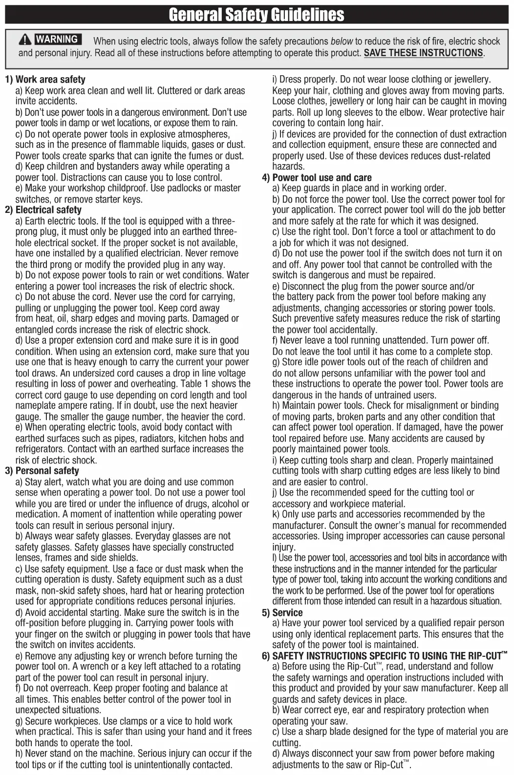
Rip-Cut Components
Rip-Cut (KMA2685-INT) Parts
| A |  | 1 | Edge guide | H |  | 1 | Indexing stop | |
| B | 2 | Self-tapping screws | I | 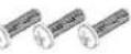 | 3 | Machine screws | ||
| C | 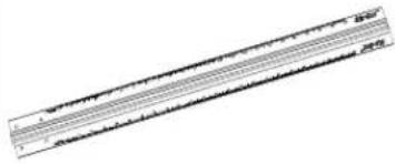 | 1 | Rail | J | 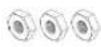 | 3 | Hex nuts | |
| D |  | 1 | Filler strip | K | 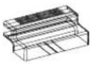 | 1 | Cursor | |
| E | 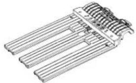 | 1 | Sled | L | 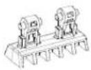 | 1 | Wedge | |
| F |  | 2 | Set screws | M |  | 1 | Handle | |
| G |  | 2 | Base-plate clamps | |||||
Assembly
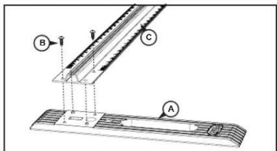
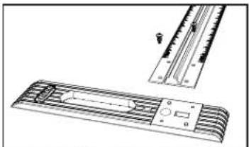
Step 1: Connect the Edge Guide to the Rail
text_image
Technical diagram showing a mechanical assembly with labeled components A, B, and C, likely illustrating a motion or positioning setup.Right-hand operation
Remove the clear tape covering the recess in the edge guide (A), remove the two self-tapping screws (B), and use them to secure the edge guide to the rail (C). Orient the edge guide for right-hand or left-hand operation as shown.
natural_image
Technical line drawing of a mechanical component with a ruler and flange (no text or symbols)Left-hand operation
Step 2: Orient the Filler Strip
text_image
G D E F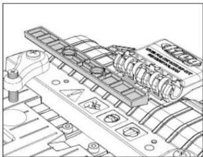
natural_image
Technical line drawing of a mechanical assembly with no visible text or symbolsThe filler strip (D) on the sled (E) is supplied with the angled ribs facing up. These ribs support a saw base with an angled leading edge, keeping the saw base flat on the sled when the set screws (F) in the base-plate clamps (G) are tightened. For a saw base with a flat leading edge, lift the filler strip from the sled recess with the tip of a screwdriver, turn it over to expose the flat face and press it into the recess.
Assembly
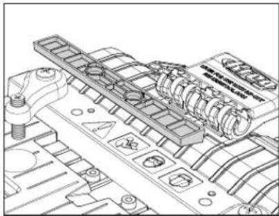
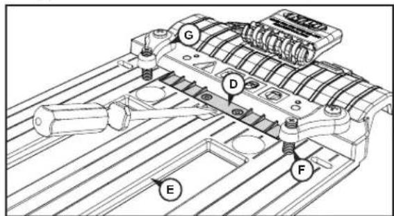
Step 3: Mount your Circular Saw on the Sled
text_image
Technical diagram of a mechanical assembly with labeled parts H, F, G, and ERemove the indexing stop (H) from the sled (E). Loosen the set screws (F) in the base-plate clamps (G) and slide your saw base plate under them. Position the saw on the sled with the front of the saw base plate against the step at the front of the sled. For saws with the blade on the left-hand end of the motor, centre the blade in the left sled slot. For saws with the blade on the right-hand end of the motor, centre the blade in the right sled slot. To accommodate different saw base-plate configurations, there are two holes for attaching each base-plate clamp to the sled. For the most secure clamping, choose the holes that provide the widest spacing allowed by your saw. The clamps can be oriented at an angle. Tighten the set screws onto the saw base plate to securely hold the saw but do not over-tighten. Make sure the saw-blade guard operates freely.

WARNING
Disconnect the saw from power before mounting it on the sled.
Step 4: Check the Position of the Cursor
text_image
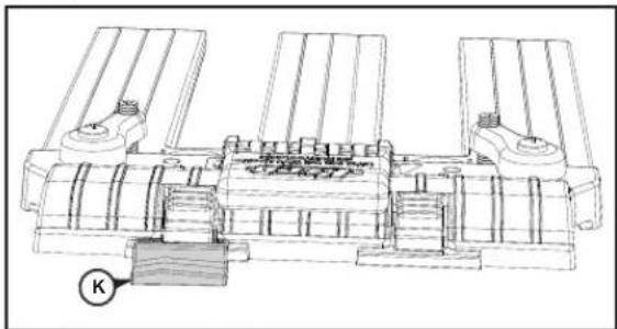
Technical diagram of a mechanical assembly with labeled component KThere are two positions on the sled for the cursor (K) that correspond to the two sled slots. Position the cursor in the holder in front of the saw blade. To switch cursor position, press down on the holder lock, slide the cursor out of the holder and reinstall it in the other holder.
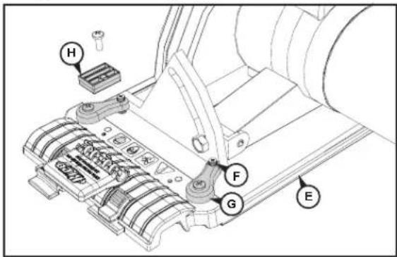
Step 5: Reinstall the Indexing Stop
text_image
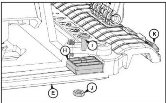
Technical diagram of a mechanical assembly with labeled parts H, I, K, E, and JThe indexing stop (H) allows you to remove the saw from the sled assembly and then re-mount it in exactly the same position. Place the indexing stop against the side of the saw base on the same side as the cursor (K) and secure it to the sled (E) with the machine screw (I) and nut (J). For maximum positioning flexibility, the sled is slotted and the indexing stop rotates 180°.

ATTENTION
The sled assembly is equipped with features that are Accu-Cut™ family of products. Additional steps, found ct manuals are required to calibrate the sled for use on
Step 6: Slide the Sled onto the Rail
text_image
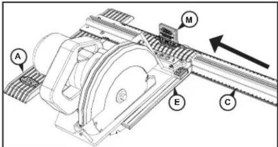
Technical diagram of a mechanical assembly with labeled components A, M, E, and CWith your saw clamped to the sled (E), raise the handle (M) to the upright position and slide the sled onto the rail (C), inserting the wedge (L) into the rail channel. The saw and the edge guide (A) should extend from the same edge of the rail.
Assembly
Step 7: Align the Cursor and Determine the Narrowest Cut
text_image
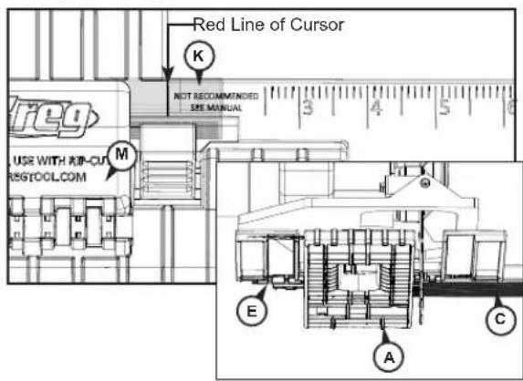
Red Line of Cursor K NOT RECOMMENDED SEE MANUAL USE WITH RIP-CU M REGTOOL.COM E A CRotate the saw blade guard up and slide the sled (E) along the rail (C) until the blade just touches the edge guide (A). Lock the sled in place by pressing down on the handle (M). The handle does not need to be completely horizontal to lock securely. Press down on the cursor lock and align the red cursor (K) with the zero mark on the rail scale. The minimum safe cut may be greater than 25mm [1"]
WARNING On the scale, the area between zero and 25mm [1"] is marked Not Recommended, See Manual. On most saws, the edge guide interferes with blade-guard operation on cuts of less than 25mm [1"], so these cuts should not be attempted. After aligning the cursor, verify the minimum safe cut width by moving the sled away from the edge guide until the blade guard functions without interference.
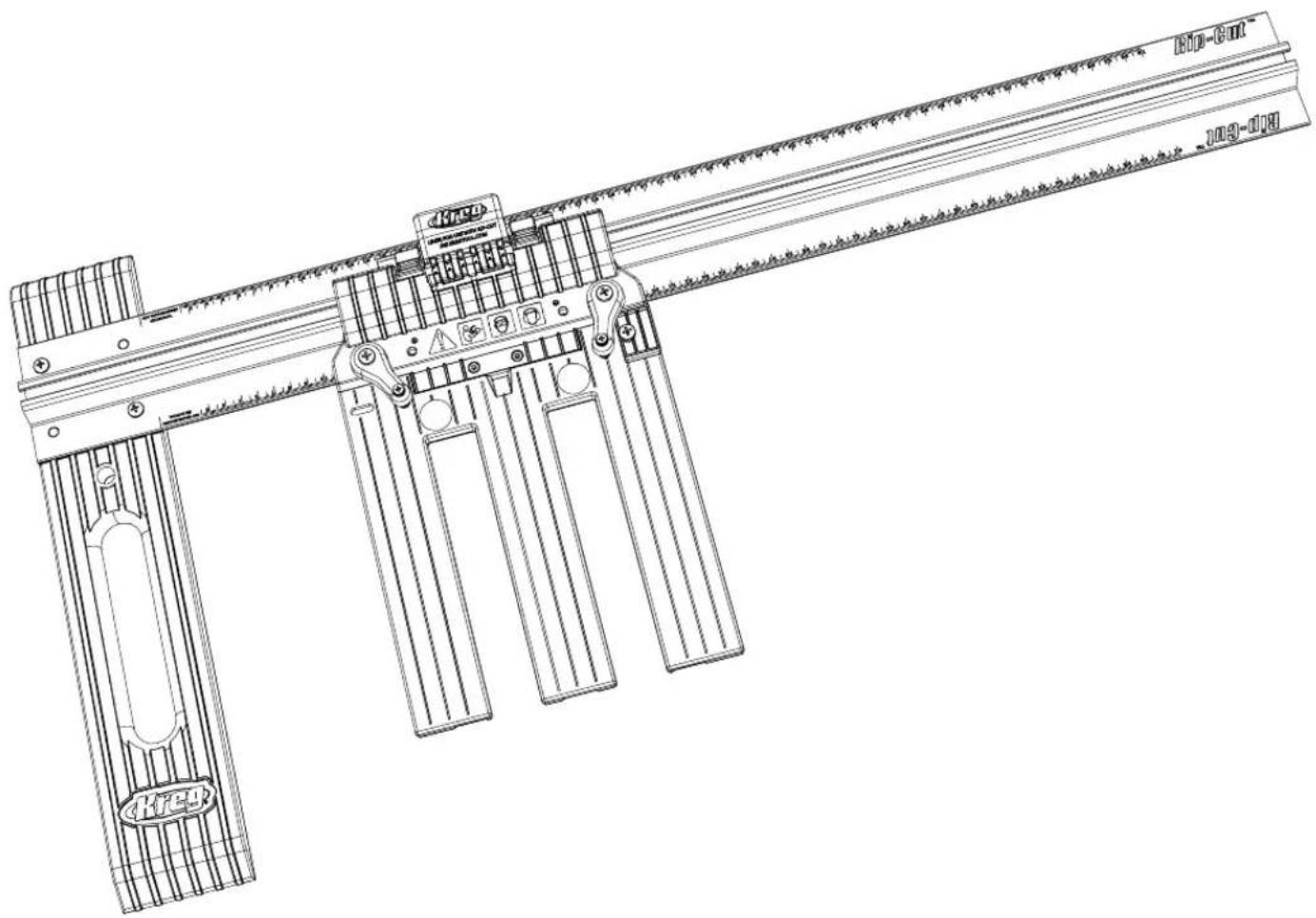
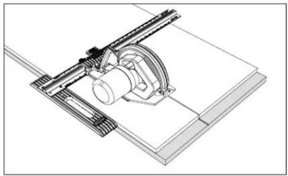
Using your Rip-Cut™
natural_image
Technical line drawing of a mechanical assembly with a cylindrical component mounted on a base plate (no text or symbols)1) For the best results, install a 40-tooth blade or better on your saw.
2) With the saw mounted on the sled, adjust the depth of cut so the blade will protrude 3mm [½"] through the workpiece during the cut.
3) Release the wedge lock and slide the sled along the rail until the cursor aligns with the desired dimension on the scale. Engage the wedge lock.
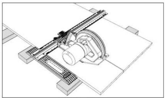
4) Completely support the workpiece and cutoff with 2x4s or 50mm [2"]-thick rigid foam insulation laid flat on the floor.
5) Connect your saw to power. With one hand on the edge guide and the other holding the saw, press the edge guide against the edge of your workpiece and make your cut, moving the edge guide and saw forward at the same speed throughout the entire cut. Allow the saw blade to come to a complete stop before lifting the Rip-Cut™ from the workpiece.
natural_image
Technical line drawing of a mechanical assembly with no visible text or symbolsWARNING When making narrow cuts, make sure the hand holding the edge guide does not come into contact with the blade.
text_image
Technical diagram showing labeled components A, B, and C for a mechanical or electrical assembly with alignment indicators.natural_image
Technical line drawing of a mechanical component with internal channels and a ruler, no text or symbols presenttext_image
Technical diagram of a mechanical assembly with labeled components (G, D, E, F) and bolted connections