Fatmax FMHT77419 - Multimeter STANLEY - Free user manual and instructions
Find the device manual for free Fatmax FMHT77419 STANLEY in PDF.
User questions about Fatmax FMHT77419 STANLEY
0 question about this device. Answer the ones you know or ask your own.
Ask a new question about this device
Download the instructions for your Multimeter in PDF format for free! Find your manual Fatmax FMHT77419 - STANLEY and take your electronic device back in hand. On this page are published all the documents necessary for the use of your device. Fatmax FMHT77419 by STANLEY.
USER MANUAL Fatmax FMHT77419 STANLEY
This instrument is warranted to be free from defects in material and workmanship for a period of one year. Any instrument found defective within one year from the delivery date and returned to the factory with transportation charges prepaid, will be repaired, adjusted, or replaced at no charge to the original purchaser. This warranty does not cover expendable items such as battery or fuse. If the defect has been caused by misuse or abnormal operating conditions, the repair will be billed at a nominal cost.
SAFETY INFORMATION
This meter has been designed according to This should be IEC 61010-1:2010 concerning electronic measuring instruments with a measurement category (CAT III 600V) and pollution degree 2.

Warning
To avoid possible electric shock or personal injury, follow these guidelines:
-
Do not use the meter if it is damaged. Before you use the meter, inspect the case. Pay particular attention to the insulation surrounding the connectors.
-
Inspect the test leads for damaged insulation or exposed metal. Check the test leads for continuity. Replace damaged test leads before you use the meter.
-
Do not use the meter if it operates abnormally. Protection may be impaired. When in doubt, have the meter serviced.
-
Do not operate the meter around explosive gas, vapor, or dust.
-
Do not apply more than the rated voltage, as marked on the meter, between terminals or between any terminal and earth ground.
-
Before use, verify the meter's operation by measuring a known voltage.
-
When measuring current, turn off circuit power before connecting the meter in the circuit. Remember to place the meter in series with the circuit.
-
When servicing the meter, use only specified replacement parts.
-
Use caution when working with voltage above 30V ac rms, 42V peak, or 60Vdc. Such voltages pose a shock hazard.
-
When using the probes, keep your fingers behind the finger guards on the probes.
-
When making connections, connect the common test lead before you connect the live test lead. When you disconnect test leads, disconnect the live test lead first.
-
Remove the test leads from the meter before you open the battery cover or the case.
-
Do not operate the meter with the battery cover or portions of the case removed or loosened.
- To avoid false readings, which could lead to possible electric shock or personal injury, replace the battery as soon as the low battery indicator ("") appears.
- Do not use the meter in a manner not specified by this manual or the safety features of the meter may be impaired.
- When in Relative mode (the symbol "△" is displayed) or in Data Hold mode (the symbol "C" is displayed), caution must be used because hazardous voltage may be present.
- Do not touch any naked conductor with hand or skin.
- Do not ground yourself.
- Do not operate this meter if your hand or the meter is wet.
- Adhere to local and national safety codes. Use Individual protective equipment to prevent shock and arc blast injury when working in an area where hazardous live conductors are exposed.
- Use only the test leads specified by the factory.
- During replacement of fuses, please only use the spare fuses from Stanley Fatmax.
- Remaining endangerment: When an input terminal is connected to dangerous live potential it is to be noted that this potential at all other terminals can occur!
- CAT III - Measurement category III is for measurements performed in the building installation. Examples are measurements on distribution boards, circuit breakers, wiring, including cables, bus-bars, junction boxes, switches, socket-outlets in the fixed installation, and equipment for industrial use and some other equipment, for example, stationary motors with permanent connection to fixed installation. Do not use the meter for measurements within Measurement Categories IV.
Caution
To avoid possible damage to the meter or to the equipment under test, follow these guidelines:
- Disconnect circuit power and discharge all capacitors before testing resistance, diode, capacitor and continuity.
- Use the proper terminals, function, and range for your measurements.
- Before measuring current, check the meter's fuses and turn off the power to the circuit before connecting the meter to the circuit.
- Before rotating the range switch to change functions, disconnect test leads from the circuit under test.
Symbol
Alternating Current
Direct Current
DC orAC
Caution, risk of danger, refer to the operating manual before use.
Caution, risk of electric shock.
Earth (ground) Terminal
Fuse
Conforms to European Union directives
The equipment is protected throughout by double insulation or reinforced insulation.
GENERAL DESCRIPTION
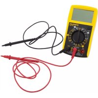
This meter is a compact 3 3/4 digits digital multimeter for measuring DC and AC voltage, DC and AC current, resistance, capacitance, frequency, diode, continuity and duty cycle. It features polarity indication, data hold, overrange indication, automatic power-off. It is easy to operate and is an ideal measurement tool.
STRUCTURE
1. Display
3 3/4-digit LCD, with a max. reading of 3999
2. "Hz%" Button
When the function/range switch is in "Hz%" position, pressing this button switches the meter between frequency and duty cycle measurements.
3. "RANGE" Button
Used to switch between autorange mode and manual range mode as well as to select desired manual range.
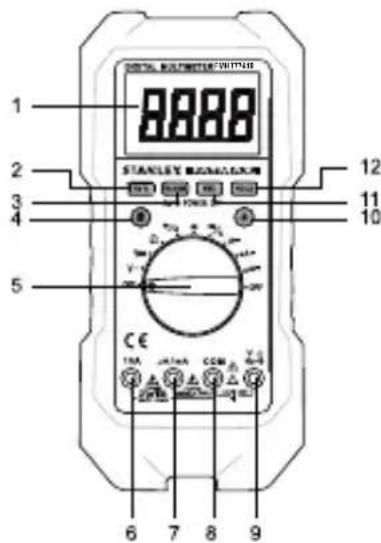
4. "S" Button
In current measurement functions, pressing this "S" button switches the meter between DC current and AC current measurements. When the Function/Range switch is in " / ") position, pressing this button switches the meter between diode and continuity measurements.
5. Function / Range Switch
Used to select the desired function and range as well as to turn on or off the meter.
6. "10A" Terminal
Plug-in connector for the red test lead for current (400mA - 10A) measurements.
7. "μA/mA" Terminal
Plug-in connector for the red test lead for the current measurements < 400mA
8. "COM" Terminal
Plug-in connector for the black test lead for all measurements.
9."VTeHaiHaI.
Terminal Plug-in connector for the red test lead for all measurements except current measurements.
10."Button
Press this button to turn on/off the backlight.
11. "REL" Button
Used to enter/exit Relative mode.
12."HOLD"Button
Used to enter/exit Data Hold mode.
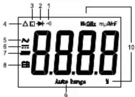
READING THE LCD

Symbol Meaning.
- Continuity test is selected.
- Diode test is selected.
- H Data Hold is enabled.
- Relative mode is active.
- AC
- DC
- Negative sign
- Battery is low and should be replaced immediately
- Auto Range Autorange mode is selected.
10. Units on the LCD
mV, V Voltage unit
mV: Millivolt; V: Volt 1V=10 ^3mV
uA, mA, A Current unit
uA: Microamp; mA: Milliamp; A: Ampere 1A = 10 ^3mA = 10^6 A
,k ,M Resistance unit
Ω: Ohm; kΩ: Kilohm; MΩ: Megohm; 1MΩ = 10 kΩ
$$ = 1 0 ^ {6} \Omega $$
nF, uF Capacitance unit
nF:Nanofarad;yF: Microfarad
$$ 1 F = 1 0 ^ {6} \mathrm {u F} = 1 0 ^ {9} \mathrm {n F} = 1 0 ^ {1 2} \mathrm {p F} $$
Hz, kHz, MHz Frequency unit
Hz: Hertz; kHz: Kilohertz; MHz: Megahertz
$$ 1 \mathrm {M H z} = 1 0 ^ {3} \mathrm {k H z} = 1 0 ^ {6} \mathrm {H z} $$
% Unit of duty cycle
%: Percent
GENERAL SPECIFICATION
Display: 3 3/4-digit LCD, with a max. reading 3999
Overrange Indication: "OL" shown on the display
Negative Polarity Indication: negative sign "——" shown on the display automatically
Sampling Rate: 2 -3 times/sec
Operating Environment: 0^ 40^, < 75% RH
Temperature Coefficient: 0.2 × (specified accuracy) /^ C ( < 18^ C or >28^ C )
Storage Environment: - 10^ 50^, < 85% RH
Operating Altitude: 0 to 2000 meters
Battery: 9V, 6F22 or equivalent, 1 piece
Low Battery Indication:" shown on the display
Size: 217x100x49mm
Weight: about 500g (including battery)
IP: 51
SPECIFICATIONS
Accuracy is specified for a period of one year after calibration and at 18^ to 28^ , with relative humidity < 75% .
Except where specified, accuracy is specified from 8% to 100% of range.
DC Voltage
| Range | Resolution | Accuracy |
| 400mV | 0.1mV | ± (1.0% + 5) |
| 4V | 0.001V | ± (0.8% + 3) |
| 40V | 0.01V | |
| 400V | 0.1V | |
| 600V | 1V | ± (1% + 5) |
Input Impedance: the range 400mV .. >1000M /the other ranges: 10MΩ
Overload Protection: 600V DC/AC rms
AC Voltage
| Range Resolution | Accuracy | |
| 4V 0.001V | ± (1.0% + 5) 40V 0.01V | |
| 400V 0.1V | ||
| 600V 1V ± (1.2% + 5) | ||
Input Impedance: 10MΩ
Frequency Range: 40Hz-400Hz
Response: Average, calibrated in rms of sine wave
Overload Protection: 600V DC/AC rms
DC Current
| Range Resolution | Accuracy | |
| 400μA 0.1μA | ± (1.2% + 3) | |
| 4000μA 1μA | ||
| 40mA 0.01mA | ± (1.5% + 3) | |
| 400mA 0.1mA | ||
| 4A | 0.001A | ± (1.8% + 3) |
| 10A | 0.01A | ± (2.0% + 5) |
Overload Protection: Fuse 1: F 400mA/690V -
Fuse 2: F 10A/690V
Max. Input Current: 10A (For inputs > 2A: measurement)
duration
< 10 secs, interval > 15 minutes)
Max. Measurement Voltage Drop: 400mV
Note: The 10A range is specified from 20% to 100% of range.
AC Current
| Range Resolution Accuracy | ||
| 400μA 0.1μA | ± (1.5% + 5) | |
| 4000μA 1μA | ||
| 40mA 0.01mA | ± (1.8% + 5) | |
| 400mA 0.1mA | ||
| 4A | 0.001A | ± (2.0% + 5) |
| 10A | 0.01A | ± (2.5% + 10) |
Overload Protection: Fuse 1: F 400mA/690V
Fuse 2: F 10A/690V
Max. Input Current: 10A (For inputs > 2A: measurement)
duration < 10 secs, interval >15 minutes)
Frequency Range: 40Hz ~ 400Hz
Response: Average, calibrated in rms of sine wave
Max. Voltage Drop: 400mV
Note: The 10A range is specified from 20% to 100% of range.
Frequency
| Range Resolution | Solution Accuracy | |
| 9.999Hz 0.00 | 1Hz ± (1.0% + 3) | |
| 99.99Hz 0.01 | Hz | ± (0.8% + 3) |
| 999.9Hz 0.1Hz | ||
| 9.999kHz 1Hz | ||
| 99.99kHz 10kHz | ||
| 999.9kHz 10kHz not specified |
Input Voltage: 1Vrms -20Vrms
Duty Cycle
| Range Resolution | Solution Accuracy | |
| 5% ~ 99% 0.1% | 1 Hz ~10kHz: ± (2% + 5) | |
| > 10kHz: not specified | ||
Input Voltage: 3Vp - p 10Vp - p
Overload Protection: 600V DC/AC rms
Resistance
| Range Resolution | Accuracy | |
| 400Ω | 0.1Ω | ± (1.0% + 5) |
| 4kΩ | 0.001kΩ | ± (1.0% + 3) |
| 40kΩ | 0.01kΩ | |
| 400kΩ | 0.1kΩ | |
| 4MΩ | 0.001MΩ | |
| 40MΩ | 0.01MΩ | ± (1.8% + 5) |
Capacitance
| Range Resolution | Accuracy | |
| 40nF 0.01nF ± (4%+20)(REL) | ||
| 400nF 0.1nF ± (3%+5)(REL) | ||
| 4μF 0.001μF | ± (4% + 5) | |
| 40μF 0.01μF | ||
| 100μF | 0.1μF | ± (8% + 5) |
For the ranges ≤ 400nF , use Relative mode (REL) to subtract the stray capacitance of the test leads and the Meter.
For the range of 100 F , wait about 30 secs for the reading to settle.
Diode Test
| Range | Introduction Remark | |
| 2V | The approximate forward voltage drop of the diode will be displayed. If the voltage drop is more than 2V, the display shows the overrange indicator "OL" | Open Circuit Voltage: about 3V Short Circuit Current: < 0.9mA |
Continuity Test
| Range | Introduction Remark | |
| ··· | The built-in buzzer will sound if the resistance is less than about 30Ω. The buzzer will not sound if the resistance is more than 150Ω | Open Circuit Voltage: about 0.45V |
Selecting Relative mode causes the meter to store the present reading as a reference for subsequent measurements and zero the display.
- Press the REL button, the meter enters the Relative mode and stores the present reading as a reference for subsequent measurements, and "△" appears as an indicator. The display reads zero.
- When you perform a new measurement, the display shows the difference between the reference and the new measurement.
- Press the REL button again, the meter exits the Relative mode.
Note: Relative mode is available only in voltage, current, capacitance and resistance measurements.
Manual Ranging and Autoranging
The meter defaults to autorange mode in measurement functions which have both autorange mode and manual range mode. When the meter is in autorange mode, "AUTORANGE" is displayed.
- Press the RANGE button to enter the manual range mode, the symbol "AUTORANGE" disappears. Each press of the RANGE button increases the range. When the highest range is reached, the meter wraps to the lowest range.
- To exit the manual range mode, press and hold down the RANGE button for about 2 seconds. The meter returns to the autorange mode and "AUTORANGE" is displayed.
Data Hold Mode
Press the HOLD button to hold the present reading on the display, the symbol "H" will appear on the display as an indicator. To exit the Data Hold mode, just press the button again. "H" disappears.
Built-In Buzzer
- When you press a button, the built-in buzzer will sound a beep if the press is effective.
- The buzzer will sound several short beeps about one minute before the meter turns off automatically and sound long beep before the meter turns off automatically.
- The buzzer will sound and the display will show "OL" in one of the following conditions:
a. The AC voltage under measurement is more than about 600V ac when the meter is in the highest AC voltage range.
b. The DC voltage under measurement is more than about 600V dc when the meter is in the highest DC voltage range.
c. The DC current under measurement is more than about 10A dc when the meter is in the highest DC current range.
d. The AC current under measurement is more than about 10A ac when the meter is in the highest AC current range.
Measuring DC or AC Voltage
- Connect the black test lead to the "COM" terminal and the red test lead to the "VΩHz-1f" terminal.
- Set the range switch to the " V = " position for dc voltage measurement or to the " V " position for ac voltage measurement.
- Select autorange mode or manual range mode with the "RANGE" button.
If you use manual range mode and don't know the magnitude of the voltage to be measured beforehand, select the highest range and then reduce it range by range until satisfactory resolution is obtained.
- Connect the test leads across the source or circuit to be measured.
- Read the output on the display. For DC voltage measurements, the polarity of red lead connection will be indicated as well.
Note: To avoid electric shock to you or damages to the meter, never apply a voltage higher than 600V between the terminals.
Measuring DC or AC Current
- Connect the black test lead to the "COM" terminal. If the current to be measured is less than 400mA , connect the red test lead to the "μA/mA" terminal. If the current is between 400mA and 10A , connect the red test lead to the "10A" terminal instead.
- Set the range switch to desired A=, mA= or position.
- Press the "S" button to select DC current or AC current measurement, the display will show the corresponding symbol.
- Turn off power to the circuit which you want to measure. Then discharge all high voltage capacitors.
- Break the circuit path to be measured, then connect the test leads in series with the circuit.
- Turn on power to the circuit, then read the display. For DC current measurements, the polarity of the red test lead connection will be indicated as well.
Note: If the magnitude of the current to be measured is not known beforehand, select the highest range and then reduce it range by
range until satisfactory resolution is obtained.
Measuring Resistance
- Connect the black test lead to the "COM" terminal and the red test lead to the "VΩHz-1F" terminal.
- Set the range switch to position.
- Connect test leads across the object to be measured.
- Read the output on the display.
Note:
- For measurements >1M the meter may take a few seconds to stabilize reading. This is normal for high resistance measurements.
- When the input is not connected, i.e. at open circuit, "OL" will be displayed as overrange indication.
- Before measurement, disconnect all power to the circuit to be tested and discharge all capacitors thoroughly.
Continuity Test
- Connect the black test lead to the "COM" terminal and the red test lead to the "VΩHz+T" terminal.
- Set the range switch to " + / ") position, then press the "S" button until the symbol " ") appears on the display.
- Connect the test leads to the circuit to be measured.
- If the circuit resistance is less than about 30 , the built-in buzzer will sound.
Note: Before test, disconnect all power to the circuit to be tested and discharge all capacitors thoroughly.
Diode Test
- Connect the black test lead to the "COM" terminal and the red test lead to the "VΩHz+F" terminal. (Note: The polarity of the red lead is positive "+"
- Set the range switch to " + / " position, then press the "S" button until the symbol " + " appears on the display.
- Connect the red test lead to the anode of the diode to be tested and the black test lead to the cathode of the diode.
- The display shows the approximate forward voltage drop of the diode. If the connection is reversed, "OL" will be shown on the display.
Measuring Capacitance
-
Connect the black test lead to the "COM" terminal and the red test lead to the "VΩHz+T" terminal.
-
Set the range switch to -1- position.
- If the display doesn't read zero, press the "REL" button.
- Connect the test leads across the capacitor to be measured.
- Wait until the reading is stable, then read the output on the display. (For high capacitance measurements, it may take about 30 seconds for reading to stabilize.)
Note: Before measurement, make sure that the capacitor to be measured has been discharged thoroughly.
Measuring Frequency and Duty Cycle
- Connect the black test lead to the "COM" terminal and the red test lead to the "VΩHz+1f" terminal.
- Set the range switch to Hz / % position. Then press the "Hz/%" button to select frequency measurement or duty cycle measurement, the display will show the corresponding unit.
- Connect the test leads across the source or load to be measured.
- Read the output on the display.
Note:
- For frequency measurements, the voltage of the input signal must be between 1V rms and 20Vrms.
- For duty cycle measurements, the voltage of the input signal must be between 3Vp-p and 10Vp-p. If the frequency of input signal is too low, the reading's stability will decrease.
- For both frequency and duty cycle measurements, if the voltage exceeds the specified range, the error of reading may be out of the specified accuracy range.
Automatic Power-off
The display will blink and the meter will go into Sleep mode if you have not turned the rotary switch or pressed button for 15 minutes. To arouse the meter from Sleep, just press a button.
To disable the automatic power-off feature, press and hold down a button while rotating the rotaryswitch from "OFF" position to other position.
MAINTENANCE

Warning
Except replacing battery and fuse, never attempt to repair or service your meter unless you are qualified to do so and have the relevant calibration, performance test, and service instructions.
General Maintenance
Periodically wipe the case with a damp cloth and mild detergent. Do not use abrasives or solvents.
Dirt or moisture in the terminals can affect readings.
Clean the terminals as follows:
- Set the range switch to OFF position and remove the test leads from the meter.
- Shake out any dirt which may exist in the terminals.
- Soak a new swab with alcohol.
- Work the swab around in each terminal.
Replacing the Battery and Fuse
Warning
To avoid false readings, which could lead to possible electric shock or personal injury, replace the battery as soon as the low battery indicator (" +") appears.
To prevent damage or injury, install only replacement fuses with the specified amperage, voltage, and interrupt ratings.
Disconnect the test leads before opening the back cover or the battery cover.
To replace the battery, remove the screws on the battery cover and remove the battery cover, replace the exhausted battery with a new battery of the same type (9V, 6F22 or equivalent). Reinstall the battery cover and the screws.
This meter uses two fuses:
To check Fuse 1:
- Remove the screws on the back cover and remove the back cover.
- Use another multimeter to check the continuity of the fuse.
To check Fuse 2:
- Set the range switch to " + / ") position, then press the "S" button until the symbol " ") appears on the display.
- Connect the red test lead to the "VΩHz-1f".
- Insert the red test lead into the "10A" terminal. If a tone is sounded, the fuse is good.
Fuse 1: F 400mA/690V, Min. Interrupt Rating 20000A, Ø10X38mm
Fuse 2: F 10A/690V, Min. Interrupt Rating 20000 A, Ø10X38mm To replace the fuse, remove the screws on the back cover and remove the back cover, replace the blown fuse with a new one of the same ratings. Reinstall the back cover and all the screws
ACCESSIONS
Manual: 1 piece
Test Lead: 1 pair
NOTE
- This manual is subject to change without notice.
- Our company will not take the responsibilities for any loss.
- The contents of this manual can not be used as the reason to use the meter for any special application.
DISPOSAL OF THIS ARTICLE
Dear Customer, If you at some point intend to dispose of this article, then please keep in mind that many of its components consist of valuable materials, which can be recycled.
Please do not discharge it in the garbage bin, but check with your local council for recycling facilities in your area.

GARANTIE
WEGWERPEN VAN UW APPARAAT
Geachte klant,
[ 1F = 10^{6}uF = 10^{9}nF = 10^{12}pF ]
12. Pulsante "HOLD "
Fusivel 2: F 10A/690V
Fusivel 2: F 10A/690V
1F = 10 ^6 F = 10^9nF = 10^12pF
$$ = 1 0 ^ {6} \mu A $$
, k, M Modstandsenhed
Ω: Ohm; kΩ: Kilo-ohm; MΩ: Megohm; 1MΩ =10 ^3k
$$ = 1 0 ^ {3} \Omega $$
nF, yF Kapacitansenhed
nF: Nanofarad; F: Mikrofarad
$$ 1 F = 1 0 ^ {6} u F = 1 0 ^ {9} n F = 1 0 ^ {1 2} p F $$
Hz, kHz, MHz Frekvensenhed
Hz: Hertz; kHz: Kilohertz; MHz: Megahertz
$$ 1 \mathrm {M H z} = 1 0 ^ {3} \mathrm {k H z} = 1 0 ^ {6} \mathrm {H z} $$
PooTaoia aTo uTepoPtown: 600V DC/AC rms
Tacon AC
CITIREA ECRANULUI LCD

1F = 10 ^6 F = 10^9nF = 10^12pF
Hz, kHz, MHz Unităti de masurare a frecventei
Hz: hertz; kHz: kilohertz; MHz: megahertz
1 MHz = 10 ^3 kHz = 10^6 Hz
Tensiunea in current alternative
Māsurarea tensiunii in current continuu Sau in current alternative
Pa3bEm IJIa Kpachoro DnaIarHOCTnueCKoro BbIBOda IJIa BCEX n3MepeHn, KpOME n3MepeHn TOka.
10. Khonka "
HaxnMaTb 3Ty KONky IJRA BKNIOUeHn/ BBIKIOUeHn NOcBETKn.
11. Khonka "REL"
IcnoIb3yeTcA DnB BXOa B OTHOCHTeHbHbI peXIM N BbIXOa I3 Hero.
12. Khonka"HOLD"(yDEPXAHNE")
IcnoIb3yETcA Inra BxOda BpeKIM ydepKaHna DaHHbIX N BbIXoDa n3 Hero.
POKA3AHNAKKDINCPIE
3haeHne cIMBOJIOB
1.
Bb6pana npOBepka 9eIOCTHOCTN cenn.
2.
BbIbpaHa npoBepka IIOoOB.
3.
BkIIOueH peXIM yIepXaHnA daHHbIX.
- AKTINBEH OTHOCHTeJIbHbI pexIM.
5.!pepeMeHHbI TOK - IOCTOHHbIM TOK
- 3HaK"MnHyc"
- BaTapepa3pXeHa, Tpe6yETcHMeDJIeHHa 3aMeHa.
- Auto Range BbI6paH peKIM aBTOMaTnueCKO nepeKIOUeHNr dnaHa 3MepeHn.
10. EdinncbHa KK dncnnee
mV,V EAnHnua HappKeHHa
mV: MnnnBONbT (MB); V: BONbT (B) 1 B = 10
uA,mA,A EunHnua cunbI TOKa
μA: Mnkpoamnp (mKA); mA: MnJnnaMnp (MA);
A: amnp (A) 1 A = 10 ^3MA = 10^6MkA
Ω, kΩ, MΩ EdnHnucbI cnpotnbJeHnA
Ω:OM; kΩ: KINOM; MΩ: meraom 1 MOm = 10
10^6 OM
nF, yF EdHHua 3JneKtpueeCKoE mKOCTn
nF:HaHocapapa(a(HΦ);μF:Mkpoφapapa(MKΦ)
1Φ=10 6MKΦ=109HΦ=1012nΦ
Hz, kHz, MHz EdnHnca yactotbl
Hz: repu (Γu); kHz: knilorepu (kΓu); MHz: merarepu
(MΓu)
1MΓu=10 3KΓu=10Γu
% EddnHua Ko3ΦΦnueHtA 3aOpJHeHn
%:npoceHT
OBUAR CNEUNKAUIN
Dncnne 3 34 -pa3pHbI KNDKOKPcTaIIHueckN Dncnne C MaKcMaJIbHbIM Noka3aHHeM 3999.
HdkaaBbIXoDa 3a npedeIbI dnaa3OHa: Ha dinpnei BbIBOJrTa6yKBbl "OL"
HnDkaun oTpncatelbHOI noJrpHoCTn: Ha dncnne
abTOMaTHueCKN BbIBOHTCQ OTPuataeHbHbI 3HaK
YacToTa DnckPeTn3aunn: 2-3 pa3a/ceK.
YcNoBn3KcnnyatauN0°C~40°C,OTHOCTeJIbHaB BnaxHOCTb<75%
TemnepaTyphbI K03ΦΦnueHr: 0,2 x (yka3aHHa TocHoCTb) /°C (<18°C nπ > 28°C)
YcnoBna XpaHnna -10°C ~ 50°C, OTHOCHTeNbHa BJaXHOCTb <85%
Paboua BbICota HaD ypoBhem MOpra: ot 0 do 2000 metpoB
Batape: 9 B, 6F22 nnn kbnBaeneH, 1 wT.
Hnkaa np3p4k6atapen: Ha nncnn BbBODNTc
CIMBOJ"
Pa3Mepbl:217x100x49MM
Macca: OKOJIO 500 r (BkJIIOUyA 6aTapeHO)
IP:51
TEXHNUECKNEXAPAKTEPNUCTUKN
ToHOCb yCTaHaBnBaEeTcHa cPOK OINH rOd NocNe KaINbPOBKn
pRi TeMnePaType 18°C - 28°C n OTHOCHTeNbHO BnaXHoCTn < 75%.
3a NCKJIIOUeHHeM OcO6o OROBOpEHbIX ClyuAeB, ToHOCtB
yCTaHaBnBaEeTcAoT 8% Do 100% dIana3OHa.
Hapjxehne noctoHHoro Toka
© 2017 Stanley Tools