
SPIW309A3WF.1 - Air-conditioner WHIRLPOOL - Free user manual and instructions
Find the device manual for free SPIW309A3WF.1 WHIRLPOOL in PDF.
| Product type | Wall-mounted split air conditioner |
| Brand | Whirlpool |
| Model | SPIW309A3WF.1 |
| Cooling capacity | 9 000 BTU/h |
| Heating capacity | 9 000 BTU/h |
| Refrigerant | R32 (GWP 675) |
| Max refrigerant charge | 2.5 kg |
| Power supply | 220-240 V, 50 Hz |
| Power cable | H07RN-F 1.0 mm² (3G) |
| Recommended circuit breaker | 16 A |
| Dimensions (Indoor unit) | 815 x 285 x 215 mm (approx.) |
| Weight (Indoor unit) | 10 kg (approx.) |
| Dimensions (Outdoor unit) | 770 x 555 x 300 mm (approx.) |
| Weight (Outdoor unit) | 30 kg (approx.) |
| Operating modes | Cooling, heating, dehumidification, ventilation |
| Special functions | 6th Sense, Around U, Jet, Sleep, Super Silent, Wi-Fi |
| Remote control | Included, AAA batteries (2×1.5 V) |
| Air filter | Washable, cleaning every 200 hours |
| Outdoor operating temperature (heating) | -7°C to 24°C |
| Outdoor operating temperature (cooling) | 21°C to 43°C |
| Recommended room area | Min. 10 m² |
| Connectivity | Wi-Fi (2.4 GHz, max power 20 dBm) |
| Spare parts | Filter, remote control, batteries |
| After-sales service | Contact authorized Whirlpool |
Frequently Asked Questions - SPIW309A3WF.1 WHIRLPOOL
User questions about SPIW309A3WF.1 WHIRLPOOL
0 question about this device. Answer the ones you know or ask your own.
Ask a new question about this device
Download the instructions for your Air-conditioner in PDF format for free! Find your manual SPIW309A3WF.1 - WHIRLPOOL and take your electronic device back in hand. On this page are published all the documents necessary for the use of your device. SPIW309A3WF.1 by WHIRLPOOL.
USER MANUAL SPIW309A3WF.1 WHIRLPOOL
Instructions for use
Gebrauchsanaeisung
- Download the complete instruction manual on docs.whirlpool.eu or call the phone number shown on the warranty booklet.
- Before using the appliance, read these safety instructions. Keep them nearby for future reference.
- These instructions and the appliance itself provide important safety warnings, to be observed at all times. The manufacturer declines any liability for failure to observe these safety instructions, for inappropriate use of the appliance or incorrect setting of controls.
- Very young children (0-3 years) should be kept away from the appliance. Young children (3-8 years) should be kept away from the appliance unless continuously supervised. Children from 8 years old and above and persons with reduced physical, sensory or mental capabilities or lack of experience and knowledge can use this appliance only if they are supervised or have been given instructions on safe use and understand the hazards involved. Children must not play with the appliance. Cleaning and user maintenance must not be carried out by children without supervision.
PERMITTED USE
- CAUTION: the appliance is not intended to be operated by means of an external switching device, such as a timer, or separate remote controlled system.
- This appliance is intended to be used in household and similar applications such as: hotels and working offices.
This appliance is not for professional use. - Always turn off the air conditioner by remote control first. Do not use the power supply circuit breaker or pull off the plug to turn it off. Disconnect the air conditioner from the power supply if it is to be left unused for a long period of time or during a thunder/lightning storm.
- Never insert obstacle in the air outlet-risk of injury. Keep ventilation openings clear of any obstruction.
- Do not place any other electrical products or household belongings under indoor unit or outdoor unit. Condensation dripping from the unit might get them wet, and may cause damage or malfunction of your property.
INSTALLATION
- The appliance must be handled and installed by two or more persons - risk of injury. Use protective gloves to unpack and install - risk of cuts.
- Installation, including electrical connections, and repairs must be carried out by a qualified technician according to national wiring rules. Do not repair or replace any part of the appliance unless specifically stated in the user manual. Keep children away from the installation site. After unpacking the appliance, make sure that it has not been damaged during transport. In the event of problems, contact the dealer or your nearest After-sales Service. Once installed, packaging waste (plastic, styrofoam parts etc.) must be stored out of reach of children - risk of suffocation. The appliance must be disconnected from all remote power supply before any installation operation - risk of electric shock. During installation, make sure the appliance does not damage the power cable - risk of fire or electric shock. Only activate the appliance when the installation has been completed.
SAFETYINSTRUCTIONS
- When moving or relocating the air conditioner, consult experienced service technicians for disconnection and reinstallation of the unit.
The appliance shall not be installed in the laundry.
ELECTRICALWARNINGS
- The power supply must be of rated voltage with special circuitry for the appliance. The diameter of the power cord must comply with requirements.
- A multi-pole switch shall be installed in the fixed wiring in accordance with the wiring rules and the appliance must be earthed in conformity with national electrical safety standards.
- An all-pole disconnection switch having a contact separation of at least 3mm in all poles should be connected in fixed wiring.
- Do not use extension leads, multiple sockets or adapters. The electrical components must not be accessible to the user after installation. Do not use the appliance when you are wet or barefoot. Do not operate this appliance if it has a damaged power cable or plug, if it is not working properly, or if it has been damaged or dropped.
- If the supply cord is damaged, it must be replaced with an identical one by the manufacturer, its service agent or similarly qualified persons in order to avoid a hazard - risk of electrical shock.
- A residual current device (RCD) having rated residual operation current not exceeding 30mA shall be incorporated in fixed wiring according to national law.
- The temperature of refrigerant circuit will be high, please keep the interconnection cable away from the copper tube.
- Ensure safe grounding and a grounding wire connected with the special grounding system of the building, installed by professionals. The appliance must be fitted with electrical leakage protection switch and an auxiliary circuit breaker with sufficient capacity. The circuit breaker must also have a magnetic and a thermal tripping function to ensure protection in case of short-circuit and overload.
| Model 9K & 12K 18K 24K | |||
| Required capacity of circuit breaker 16A | 20A 25A |
- For the connection of power cord and cable connection between indoor and outdoor units, please see the wiring diagram on the appliance.
CLEANING AND MAINTENANCE
- WARNING: Ensure that the appliance is switched off and disconnected from the power supply before performing any maintenance operation; never use steam cleaning equipment - risk of electric shock.
- Maintenance and repair requiring the assistance of other skilled personnel shall be carried out under the supervision of the person competent in the use of flammable refrigerants.
Servicing shall only be performed with equipment as recommended by the manufacturer.
DISPOSAL OF PACKAGING MATERIALS
The packaging material is 100% recyclable and is marked with the recycle symbol ( ). The various parts of the packaging must therefore be disposed of responsibly and in full compliance with local authority regulations governing waste disposal.
DISPOSAL OF HOUSEHOLD APPLIANCES
This appliance is manufactured with recyclable or reusable materials. Dispose of it in accordance with local waste disposal regulations. For further information on the treatment, recovery and recycling of household electrical appliances, contact your local authority, the collection service for household waste or the store where you purchased the appliance. This appliance is marked in compliance with European Directive 2012/19/EU, Waste Electrical and Electronic Equipment (WEEE). By ensuring this product is disposed of correctly, you will help prevent negative consequences for the environment and human health.
The ( )symbol on the product or on the accompanying documentation indicates that it should not be treated as domestic waste but must be taken to an appropriate collection center for the recycling of electrical and electronic equipment.
DECLARATIONS OF CONFORMITY
- The complete text of the declaration of conformity is present at the following website: docs.whirlpool.eu.
- The radio equipment operates in the 2.4 GHz ISM frequency band, the maximum radio-frequency power transmitted does not exceed 20 dBm (e.i.r.p.).
- This product includes certain open source software developed by third parties. The open source license usage statement is available at the following website: docs.whirlpool.eu.
- This product contains Fluorinated Greenhouse Gases covered by the Kyoto Protocol, the refrigerant gas being in a hermetically sealed system (R32, GWP 675). The maximum refrigerant charge amount is 2.5kg . Please refer to the rating label for detailed information.
SAFETY INSTRUCTIONS FOR SERVICING APPLIANCE WITH SPESIFIC REFRIGERANT
- Download the complete manual for detailed installation, servicing, maintenance and repairing methods on docs.whirlpool.eu.
- Do not use means to accelerate the defrosting process or to clean, other than those recommended by the manufacturer.
- The appliance shall be stored in a well-ventilated area where the room size corresponds to the room area as specified for operation; without continuously operating ignition sources (such as; open flames, an operating gas appliance or an operating electric heater).
-
Do not pierce or burn. Be aware that the refrigerants may not contain an odor.
-
Any person who is involved with working on or breaking into a refrigerant circuit should hold a current valid certificate from an industry-accredited assessment authority, which authorizes their competence to handle refrigerants safely in accordance with an industry recognized assessment specification. Servicing shall only be performed as recommended by the equipment manufacturer. Maintenance and repair requiring the assistance of other skilled personnel shall be carried out under the supervision of the person competent in the use of flammable refrigerants. Appliance shall be installed, operated and stored in a room with a floor area larger than 10m^2 . The installation of pipe-work shall be kept to a room with a floor area larger than 10m^2 . The pipe-work shall be compliance with national gas regulations. The maximum refrigerant charge amount is 2.5kg . Mechanical connectors used indoors shall comply with ISO 14903. When mechanical connectors are reused indoors, sealing parts shall be renewed. When flared joints are reused indoors, the flare part shall be re fabricated. The installation of pipe-work shall be kept to a minimum. Mechanical connections shall be accessible for maintenance purposes.
-
Transport of equipment containing flammable refrigerants shall be compliant with the
transport regulations.
- Marking of equipment using signs shall be compliant with local regulations.
- Disposal of equipment using flammable refrigerants shall be compliant with national regulations.
- The storage of equipment / appliances should be in accordance with the manufacturer's instructions.
- Storage of packed (unsold) equipment Storage package protection should be constructed such that mechanical damage to the equipment inside the package will not cause a leak of the refrigerant charge. The maximum number of pieces of equipment permitted to be stored together will be by local regulations.
- Information on servicing.
6-1 Checks to the area
Prior to beginning work on system containing flammable refrigerants, safety checks are necessary to ensure that the risk of ignition is minimized. For repair to the refrigerating system the following precautions shall be complied with prior to conducting work on the system.
6-2 Work procedure
Work shall be undertaken under a controlled procedure so as to minimize the risk of flammable gas or vapour being present while the work is being performed.
6-3 General work area
All maintenance staff and others working in the local area shall be instructed on the nature of work being carried out. Work in confined spaces shall be avoided. The area around the workspace shall be sectioned off. Ensure that the conditions within the area have been made safe by control of flammable material.
6-4 Checking for presence of refrigerant
The area shall be checked with an appropriate refrigerant detector prior to and during work, to ensure the technician is aware of prtentially flammable atmospheres. Ensure thathte leak detection equipment being used is suitable for use with flammable refrigerants, i.e. non-sparking adequately sealed or intrinsically safe.
6-5 Presence of fire extinguisher
If any hot work is to be conducted on the refrigeration equipment or any associated partsappropriate fire extinguishing equipment shall be available to hand. Have a dry powder or CO_2 fire extinguisher adjacent to the charging area.
6-6 No ignition sources
No person carrying out work in relation to a refrigeration system which involves exposing any pipe work that contains or has contained flammable refrigerant shall use any sources of ignition in such a manner that it may lead to the risk of fire or explosion. All possible ignition sources, including cigarette smoking, should be kept sufficiently far away from the site of installation, repairing, removing and disposal, during which flammable refrigerant can possibly be released to the surrounding space. Prior to work taking place, the area around the equipment is to be surveyed to make sure that there are no flammable hazards or ignition risks. "No Smoking" signs shall be displayed.
6-7 Ventilated area
Ensure that the area is in the open or that it is adequately ventilated before breaking into the system or conducting any hot work. A degree of ventilation shall continue during the period that the work is carried out. The ventilation should safely disperse any
released refrigerant and preferably expel it externally into the atmosphere.
6-8 Checks to the refrigeration equipment
Where electrical components are being changed, they shall be fit for the purpose and to the correct specification. At all times the manufacturer's maintenance and service guidelines shall be followed. If in doubt consult the manufacturer's technical department for assistance. The following checks shall be applied to installations using flammable refrigerants:
- The charge size is in accordance with the room size within which the refrigerant containing parts are installed;
- The ventilation machinery and outlets are operating adequately and are not obstructed;
- If an indirect refrigerating circuit is being used, the secondary circuit shall be checked for the presence of refrigerant;
- Marking to the equipment continues to be visible and legible. Markings and signs that are illegible shall be corrected;
- Refrigeration pipe or components are installed in a position where they are unlikely to be exposed to any substance which may corrode refrigerant containing components, unless the components are constructed of materials which are inherently resistant to being corroded or are suitably protected against being so corroded.
6-9 Checks to electrical devices
Repair and maintenance to electrical components shall include initial safety checks and component inspection procedures. If a fault exists that could compromise safety, then no electrical supply shall be connected to the circuit until it is satisfactory dealt with. If the fault cannot be corrected immediately but it is necessary to continue operation, an adequate temporary solution shall be used. This shall be reported to the owner of the equipment so all parts are advised. Initial safety checks shall include:
- That capacitors are discharged: this shall be done in a safe manner to avoid possibility of sparking;
- That there no live electrical components and wiring are exposed while charging, recovering or purging the system;
-
That there is continuity of earth bonding.
-
Repairs to sealed components
During repairs to sealed components, all electrical supplies shall be disconnected from the equipment being worked upon prior to any removal of sealed electrical supply to equipment during servicing, then a permanently operating form of leak detection shall be located at the most critical point to warn of a potentially hazardous situation. Particular attention shall be paid to the following to ensure that by working on coelectrical components. The casing is not altered in such a way that the level of protection is affected. This shall include damage to cables, excessive number of connections, terminals not made to original specification, damage to seals, incorrect fitting of glands, etc. Ensure that apparatus is mounted securely. Ensure that seals or sealing materials have not degraded such that they no longer serve the purpose of preventing the ingress of flammable atmospheres. Replacement parts shall be in accordance with the manufacturer's specifications.
NOTE:
The use of silicon sealant may inhibit the effectiveness of some types of leak detection equipment. Intrinsically safe components do not have to be isolated prior to working on them.
- Repair to intrinsically safe components
Do not apply any permanent inductive or capacitance loads to the circuit without ensuring that this will not exceed the permissible voltage and current permitted for the equipment in use. Intrinsically safe components are the only types that can be worked on whilelive in the presence of a flammable atmosphere. The test apparatus shall be at the correct rating. Replace components only with parts specified by the manufacturer. Other parts may result in the ignition of refrigerant atmosphere from a leak.
- Cabling
Check that cabling will not be subject to wear, corrosion, excessive pressure, vibration, sharp edges or any other adverse environmental effects. The check shall also take into account the effects of aging or continual vibration from sources such as compressors or fans.
10.Detection of flammable refrigerants
Under no circumstances shall potential sources of ignition be used in the searching for or detection of refrigerant leaks. A halide torch (or any other detector using a naked flame) shall not be used.
11.Leak detection methods
The following leak detection methods are deemed acceptable for systems containing flammable refrigerants:
- Electronic leak detectors shall be used to detect flammable refrigerants, but the sensitivity may not be adequate, or may need re-calibration (Detection equipment shall be calibrated in a refrigerant-free area.)
- Ensure that the detector is not a potential source of ignition and is suitable for the refrigerant used.
- Leak detection equipment shall be set at a percentage of the LFL of the refrigerant and shall be calibrated to the refrigerant employed and the appropriate percentage of gas (25% maximum) is confirmed.
- Leak detection fluids are suitable for use with most refrigerants but the use of detergents containing chlorine shall be avoided as the chlorine may react with the refrigerant and corrode the copper pipe-work.
- If a leak is suspected, all naked flames shall be removed/ extinguished.
- If a leakage of refrigerant is found which requires brazing, all of the refrigerant shall be recovered from the system, or isolated (by means of shut off valves) in a part of the system remote from the leak.
-
Oxygen free nitrogen (OFN) shall then be purged through the system both before and during the brazing process.
-
Removal and evacuation
-
When breaking into the refrigerant circuit to make repairs - or for any other purpose conventional procedures shall be used. However, it is important that best practice is followed since flammability is a consideration.
The following procedure shall be adhered to:
- Remove refrigerant;
-
Purge the circuit with inert gas;
Evacuate; -
Purge again with inert gas;
- Open the circuit by cutting or brazing.
The refrigerant charge shall be recovered into the correct recovery cylinders. The system shall be "flushed" with OFN to render the unit safe. This process may need to be repeated several times. Compressed air or oxygen shall not be used for this task. Flushing shall be achieved by breaking to fill until the working pressure is achieved, then venting to atmosphere, and finally pulling down to a vacuum. This process shall be repeated until no refrigerant is within the system. When the final charge is used, the system shall be vented down to atmospheric pressure to enable work. This operation is absolutely vital if brazing operations, on the pipe-work are to take place. Ensure that the outlet for the vacuum pump is not close to any ignition sources and there is the vacuum in the system with OFN and continuing ventilation available.
13. Charging procedures
In addition to conventional charging procedures, the following requirements shall be followed:
- Ensure that contamination of different refrigerants does not occur when using charging equipment.
- Hoses or lines shall be as short as possible to minimize the amount of refrigerant contained in them.
- Cylinders shall be kept upright.
- Ensure that the refrigeration system is earthed prior to charging the system with refrigerant.
- Label the system when charging is complete (if not already).
- Extreme care shall be taken not to overfill the refrigeration system. Prior to recharging the system it shall be pressure tested with OFN.
The system shall be leak tested on completion of charging but prior to commissioning. A follow up leak test shall be carried out prior to leaving the site.
14.Decommissioning
Before carrying out this procedure, it is essential that the technician is completely familiar with the equipment and all its detail. It is recommended good practice that all refrigerants are recovered safely. Prior to the task being carried out, an oil and refrigerant sample shall be taken in case analysis is required prior to re-use of reclaimed refrigerant. It is essential that electrical power is available before the task is commenced.
a. Become familiar with the equipment and its operation.
b. Isolate system electrically.
c. Before attempting the procedure ensure that:
- Mechanical handling equipment is available, if required, for handling refrigerant cylinders;
- All personal protective equipment is available and being used correctly;
- The recovery process is supervised at all times by a competent person;
- Recovery equipment and cylinders conform to the appropriate standards.
d. Pump down refrigerant system, if possible.
e. If a vacuum is not possible, make a manifold so that refrigerant can be removed from various parts of the system.
f. Make sure that cylinder is situated on the scales before recovery takes place.
g. Start the recovery machine and operate in accordance with manufacturer's instructions.
h. Do not overfill cylinders. (No more than 80% volume liquid charge).
i. Do not exceed the maximum working pressure of the cylinder, even temporarily.
j. When the cylinders have been filled correctly and the process completed, make sure that the cylinders and the equipment are removed from site promptly and all isolation valves on the equipment are closed off.
k. Recovered refrigerant shall not be charged into another refrigeration system unless it has been cleaned and checked.
15.Labelling
Equipment shall be labelled stating that it has been de-commissioned and emptied of refrigerant. The label shall be dated and signed. Ensure that there are labels on the equipment stating the equipment contains flammable refrigerant.
16.Recovery
When removing refrigerant from a system, either for servicing or decommissioning, it is recommended good practice that all refrigerants are removed safely. When transferring refrigerant into cylinders, ensure that only appropriate refrigerant recovery cylinders are employed. Ensure that the correct number of cylinders for holding the total system charge is available. All cylinders to be used are designated for the recovered refrigerant and labelled for that refrigerant (i.e. special cylinders for the recovery of refrigerant).
Cylinders shall be complete with pressure relief valve and associated shutoff valves in good working order. Empty recovery cylinders are evacuated and, if possible, cooled before recovery occurs. The recovery equipment shall be in good working order with a set of instructions concerning the equipment that is at hand and shall be suitable for the recovery of flammable refrigerants. In addition, a set of calibrated weighing scales shall be available and in good working order. Hoses shall be complete with leak-free disconnect couplings and in good condition. Before using the recovery machine, check that it is in satisfactory working order, has been properly maintained and that any associated electrical components are sealed to prevent ignition in the event of a refrigerant release. Consult manufacturer if in doubt. The recovered refrigerant shall be returned to the refrigerant supplier in the correct recovery cylinder, and the relevant Waste Transfer Note arranged. Do not mix refrigerants in recovery units and especially not in cylinders. If compressors or compressor oils are to be removed, ensure that they have been evacuated to an acceptable level to make certain that flammable refrigerant does not remain within the lubricant. The evacuation process shall be carried out prior to returning the compressor to the suppliers. Only electric heating to the compressor body shall be employed to accelerate this process. When oil is drained from a system, it shall be carried out safely. When moving or relocating the air conditioner, consult experienced service technicians for disconnection and reinstallation of the unit. Do not place any other electrical products or household belongings under indoor unit or outdoor unit. Condensation dripping from the unit might get them wet, and may cause damage or malfunction of your property. To keep ventilation openings clear of obstruction. The appliance shall be stored in a well-ventilated area where the room size corresponds to the room area as specified for operation. The appliance shall be stored in a room without continuously operating open flames (for example an operating gas appliance) and ignition sources (for example an operating electric heater). Reusable mechanical connectors and flared joints are not allowed.
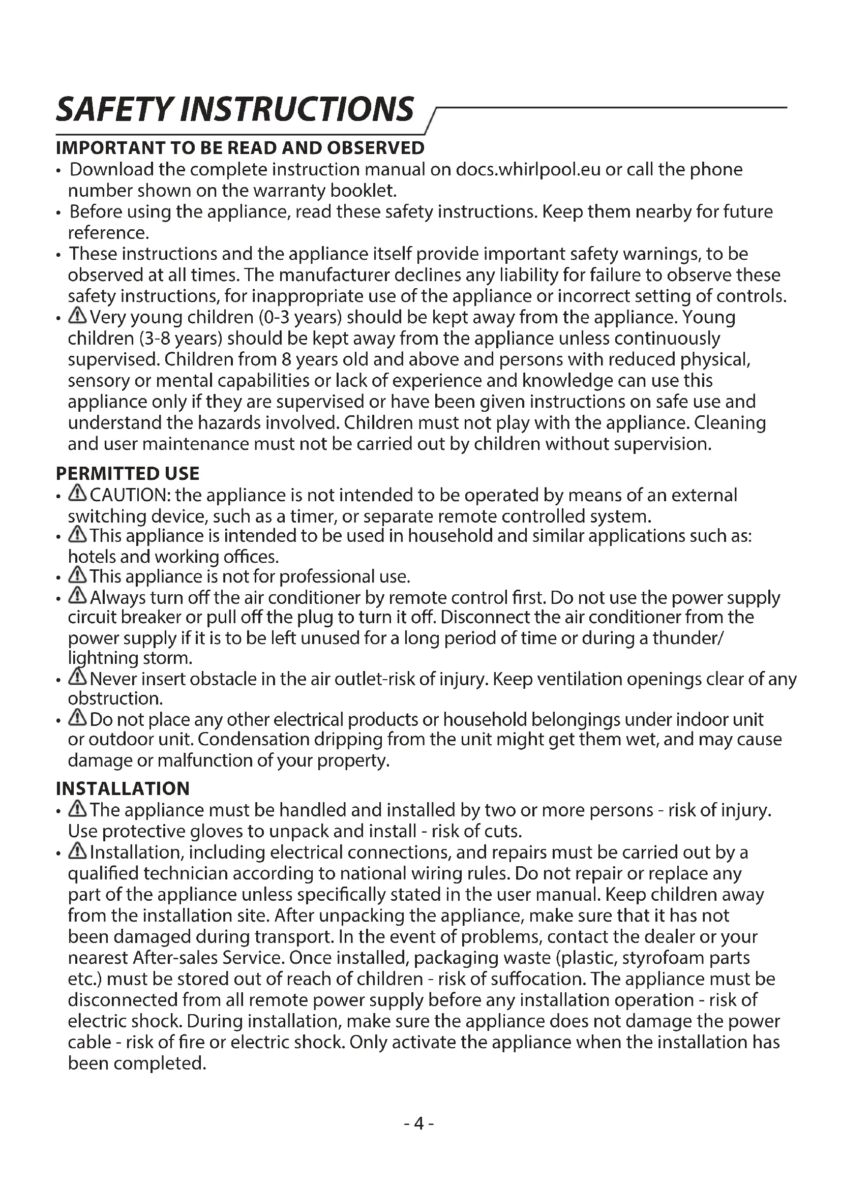
Product description
Indoor unit
The figures in this manual are based on the external view of a standard model. Consequently, the shape may differ from that of the air conditioner you have selected.
Explanation of symbols displayed on the indoor unit or outdoor unit.
| WARNING | This symbol shows that this appliance uses a flammable refrigerant is leaked and exposer to an external ignition source, there is a risk of fire. | |
| CAUTION | Ythis symbol shows that the operation manual should be read carefully. | |
| CAUTION | This symbol shows that a service personnel should be handling this equipment with reference to the installation manual. | |
| CAUTION | This symbol shows that information is available such as the operating manual or installation manual. |
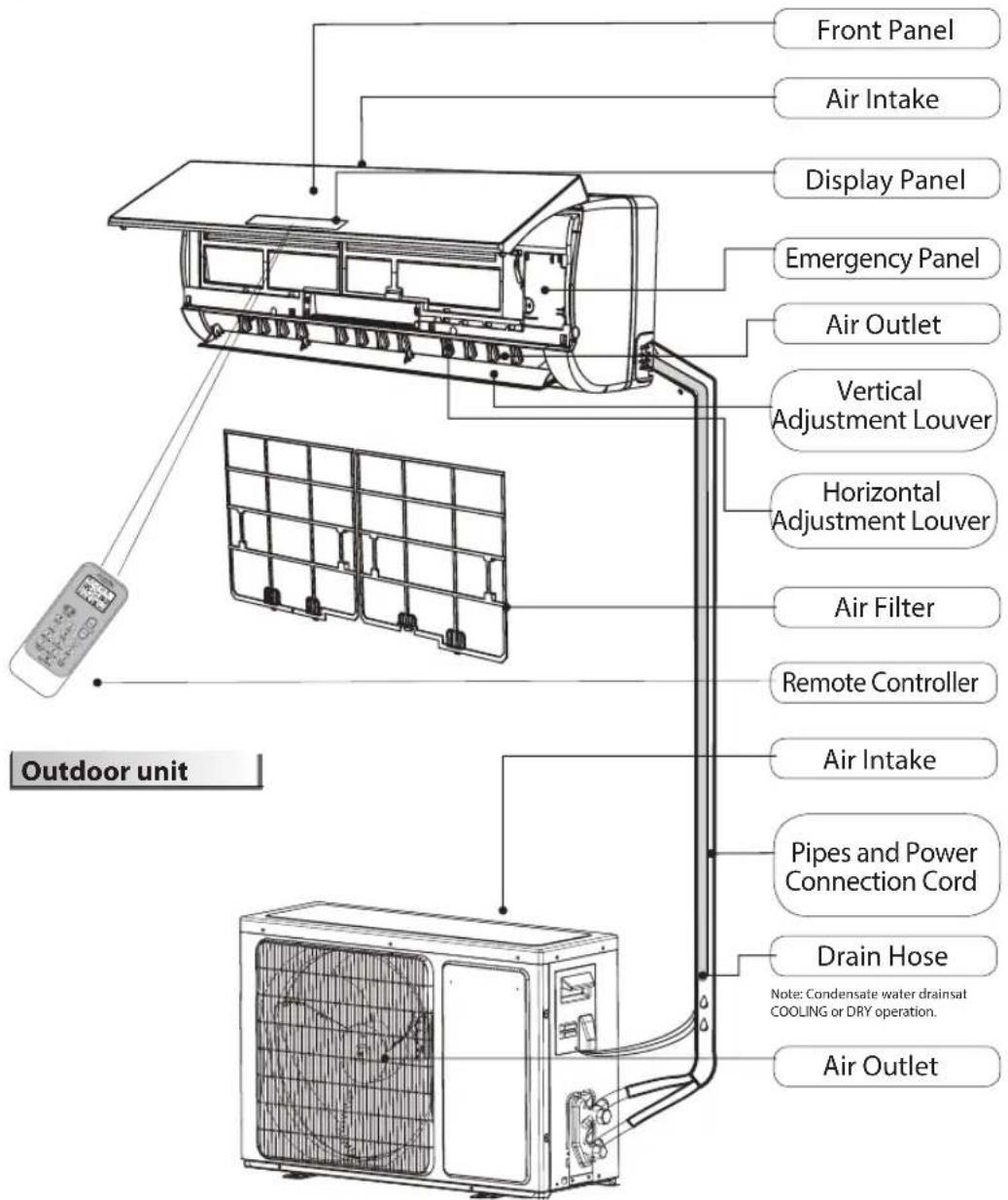
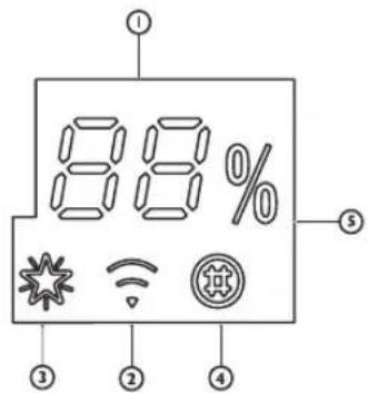
Temperature indicator (1)
Displays set temperature. It shows "FC" as a reminder to clean the filter.
Wi-Fi indicator (2)
It blinks fast (3 Hz) when it's connecting to router or lose connection to router. It blinks slowly (1.5 Hz) when it's connected to router but not connected to cloud. It turns to be solid when the Wi-Fi is fully connected. It goes off when the Wi-Fi is deprovisioned or turn off.
6th Sence indicator (3)
It lights up when 6th sense is on. It goes off when 6th sense ends.
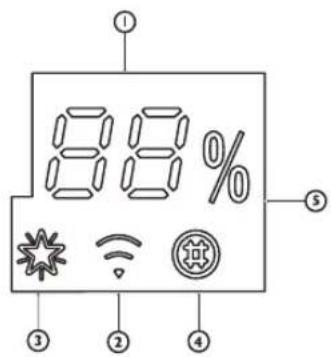
Filter monitor indicator (4)
Iit flashes when the filter needs to be cleaned. Filter monitor indicator flashes after 720 hours of usage as reminder to clean the filter. After filter cleaning, press the filter reset button located on the indoor unit behind the front panel in order to interrupt the flashing of the filter monitor indicator.
Humidity indicator (5)
It lights up when showing the humidity level. It goes off when showing the temperature.
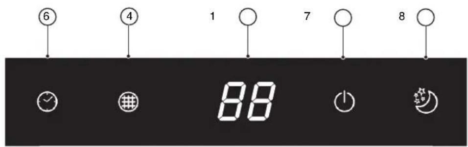
Timer indicator (6)
It lights up during the set time. It goes off when timer operation ends.
Running indicator (6)
It lights up during operation. It flashes during outside unit defrosting.
Sleep indicator (8)
It lights up once sleep mode is set, "Running" indicator will flash for 10 times then the whole display will light off.
For air conditioners without Wi-Fi control, we recommend the Wpro SmartClim: a smart device to control via Wi-Fi the main settings of your appliance from your smartphone.
This accessory is not included inside the product packaging. Please contact our After-Sales Service for more details and purchase.
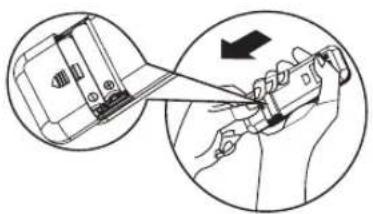
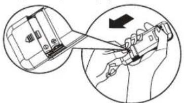
Insert the batteries into RC
- Insert a pin and gently press down on the battery cover and push in the direction of the arrow to remove, as shown.
- Insert 2 AAA batteries (1.5V) into the compartment. Ensure that "+" and -" polarity is correctly positioned.
- Close the battery cover on the remote control.
- Remote Control presetting
Each time the batteries are replaced in the remote controller, the remote controller pre-set at Heat Pump mode. The heat pump AC remote controller can be used to control the cool only AC models.
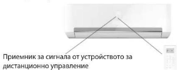
Use RC to control the appliance
- To operate the appliance by remote control, point the remote control at the receiving device on the indoor unit, to ensure receiving sensibility.
- To send a message from remote control, the symbol will flash for 1 second. On receipt of the message, the appliance will emit a beep.
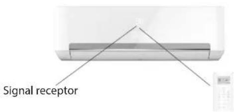
The remote control will operate the air conditioner at a distance of up to 7m.
Each time the batteries are replaced in the remote control, the remote control is pre-set at Heat Pump mode.
Note: please follow the instruction which matches to the remote controller you receive for Air Conditioner operation
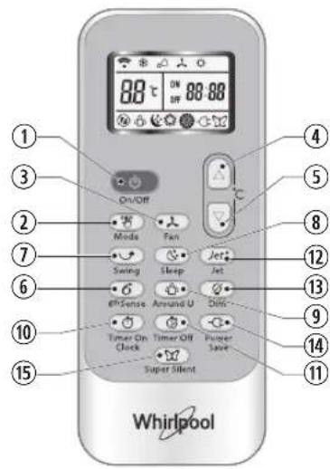
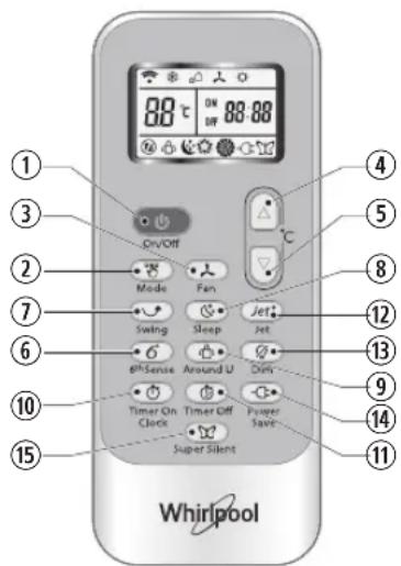
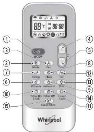
Function description of buttons (P1-03)
1. ON/OFF BUTTON
Starts or Stops the appliance by pressing this button.
3.FAN BUTTON
Used to select fan speed in sequence auto, high, medium or low.
4-5. TEMPERATURE BUTTON
Used to select the room temperature.
Used to set the time in timer mode.
6.6th SENSE BUTTON
Sets or cancels 6th sense operation.
7. SWING BUTTON
Stops or starts horizontal adjustment louver swinging and sets the desired up/down airflow direction.
10-11. HUMIDITY BUTTON
Used to set desired humidity level, they are only available under 6th SENSE mode.
16. SUPER SILENT BUTTON
Used to start or stop the super silent operation to have a low noise environment.
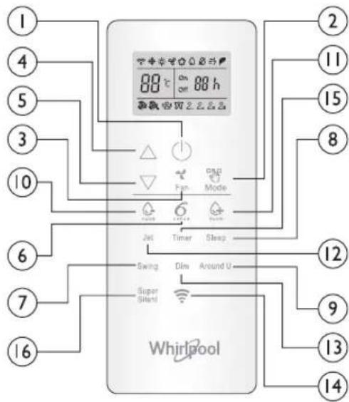
2. MODE BUTTON
Used to select the operation mode. In sequence Cooling, hearing or fan..
8.SLEEP BUTTON
Used to select the sleep mode in sequence of sleep 1, sleep 2, sleep 3, sleep 4 and sleep off.
9.AROUNDUBBUTTON
Used to set or cancel Around U function.
12.JET BUTTON
Used to start or stop the fast cooling or heating.
13.DIM BUTTON
Used to turn on or turn off display light on indoor unit.
14.WI-FIBUTTON
Used to trun on or turn off the Wi-Fi.
15TIMER BUTTON
Used to set the time for turn on or turn off the appliance.
Symbols on RC display Active RC by pressing UNLOCK button
Cooling indicator Auto fan speed Sleep indicator 1 2
Humidity plus indicator High fan speed Sleep indicator
Humidity minus indicator Medium fan speed Sleep indicator 3
Fan only indicator Low fan speed Sleep indicator 4
Heating indicator Super silent indicator
Around U indicator 6
Jet indicator Power save indicator

BB Display set temperature
品 88h Display set timer
Signal transmission
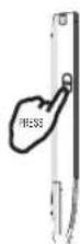
Press the button, the backlight will lighted up and function buttons will be activated for use. Press again to lock remote controller. If no operation on remote controller for 10s, the remote controller will be locked automatically.
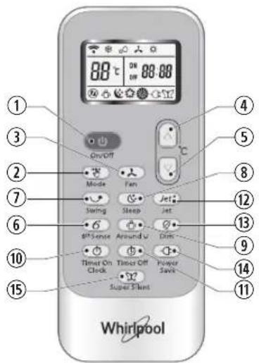
Function description of buttons (J1-3A)
1. ON/OFF BUTTON
Starts or Stops the appliance by pressing this button.
2. MODE BUTTON
Used to select the operation mode in sequence of Cooling, dry, fan only or heating.
3. FAN BUTTON
Used to select fan speed in sequence auto, high, medium or low.
Used to select the room temperature. Used to set time in timer mode and real time clock.
6.6 ^TH SENSE BUTTON
Sets or cancels 6^th sense operation.
7.SWING BUTTON
Stops or starts horizontal adjustment louver swinging and sets the desired up/down airflow direction.
8.SLEEP BUTTON
Sets or cancels Sleep Mode operation in sequence of
9. AROUND U BUTTON
Used to set or cancel Around U function.
10. TIMER ON/CLOCK BUTTON
Used to set the current time.
Used to set or cancel the timer on operation.
11 TIMER OFF BUTTON
Used to set or cancel the timer off operation.
12.JET BUTTON
Used to start or stop the fast cooling or heating mode.
13. DIM BUTTON
Used to turn on or turn off display light on indoor unit. 14. POWER SAVE BUTTON
Used to start or stop the power save operation.
15. SUPER SILENT BUTTON
Used to start or stop the super silent operation to have a low noise environment.
Symbols on RC display
Cooling indicator Sleep 1 indicator Auto fan speed
Dry indicator Sleep 2 indicator High fan speed
Fan only indicator Sleep 3 indicator Medium fan speed
Heating indicator Sleep 4 indicator Low fan speed
6 ^th Sense indicator Around indicator Super silent indicator
② Jet indicator
Signal transmission
Display set timer
Display current time
88 Display set temperature
Power save indicator
PROTECTION
Operating condition
The protective device maybe trip and stop the appliance in the cases listed below.
| Heating Outdoor | air temperature is over 24°C |
| Outdoor air temperature is below -7°C | |
| Room temperature is over 27°C | |
| Cooling Outdoor | air temperature is over 43°C |
| Room temperature is below 21°C | |
| Dehumidifying | Room temperature is below 18°C |
If the air conditioner runs in COOLING or DRY mode with door or window opened for a long time when relative humidity is above 80% , dew may drip down from the outlet.
Features of protection device
Wait at least 3 minutes before restarting the unit after operation stops or changing mode during operation. After connecting to power supply and turning on the appliance immediately, a delay of 20 seconds may occur before it starts to operate. If all operation has stopped, press ON/OFF button again to restart. Timer should be set again if it has been cancelled.
Features of COOLING mode Anti-freezing
When the temperature of the indoor
heat exchanger drops to 0^ or below, compressor will stop working to protect the appliance.
Features of HEATING mode Preheating
In order to prevent cool air blowing, 2-5 minutes are necessary to preheat the indoor unit at HEATING operation start. The indoor fan will not work during preheating.
Defrosting
In HEATING operation the appliance will defrost (de-ice) automatically to raise efficiency. This procedure usually lasts 6-10 minutes. During defrosting, fan stops running and running indicator flashes.
After defrosting is completed, it returns to HEATING mode automatically.
Clean front panel of Indoor Unit
- Disconnect from the power supply
Turn off the appliance first before disconnecting from power supply.
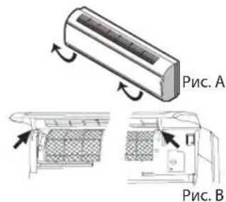
- Remove the front panel
Open the front panel as shown by the arrow (Fig. A).
Pull the slots at the side of the front panel with force to take out the front panel (Fig. B).
- Clean the front panel
Wipe it with a soft and dry cloth. Use lukewarm water (below 40^ ) to clean if the appliance is very dirty. After cleaning let it dry.
- Refit and close the front panel
Refit and close the front panel by pushing it downward.
Note:
- Do not use substances such as gasoline or polishing powder to clean the appliance.
- Do not sprinkle water onto the indoor unit Dangerous! Electric shock!
Clean Air filter
It is necessary to clean the air filter after using it for about 200 hours. Clean the air filter every two weeks if the air conditioner operates in an extremely dusty environment.
- Disconnect from the power supply
Turn off the appliance first before disconnecting from power supply.
-
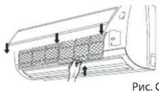
Take out air filter (Fig. C).
-
Open the front panel. 2. Press the handle of the filter gently. 3. Slide out the filter.
-
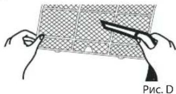
Cleaning the air filter (Fig. D)
If the filter is very dirty, clean it with a solution of lukewarm water and neutral detergent.
After cleaning let it dry.
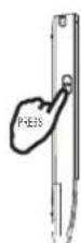
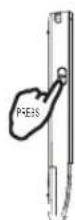
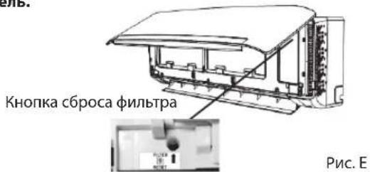
- Refit the filter, press the filter reset button (Fig.E) at right side by using a cylinder pin and close the front panel.
Note:
- To avoid injury, do not touch the fins of indoor unit with your fingers after removing the filter.
- Do not attempt to clean the inside of the air conditioner by yourself.
- Do not clean the filter in washing machine.
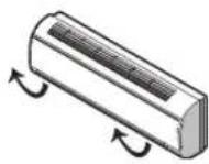
Fig.A
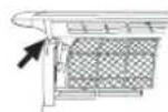
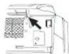
Fig.B
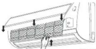
Fig.C
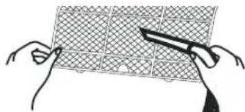
Fig.D
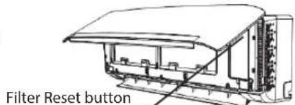
Fig.E
EMERGENCY OPERATION
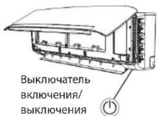
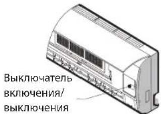
Under emergency situation or when remote control is missing, you can control the unit by pressing the on/off swith located on the indoor unit.
- Turn on the appliance: when the unit is off, press this button, it will start up and operate in 6th SENSE mode.
- Turn off the appliance: when the unit is on, press this button, the unit will stop working.
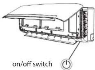
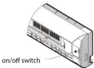
Note: Do not press this button for a long time as it will cause malfunction.
Auto-Restart Function
If you want to set auto_restart, switch on the power supply, press the ON/OFF button on the indoor unit and hold for over 5 seconds, auto_restart is set with buzz sound.
If the auto_restart has been set, press the ON/OFF button on the indoor unit and hold for over 5 seconds, auto_restart function will be cancelled with a buzz sound and air conditioner is on standby mode.
Disposal of the batteries
To protect natural resources and to promote material reuse, please separate batteries from other types of waste and recycle them through your local, free battery return system.
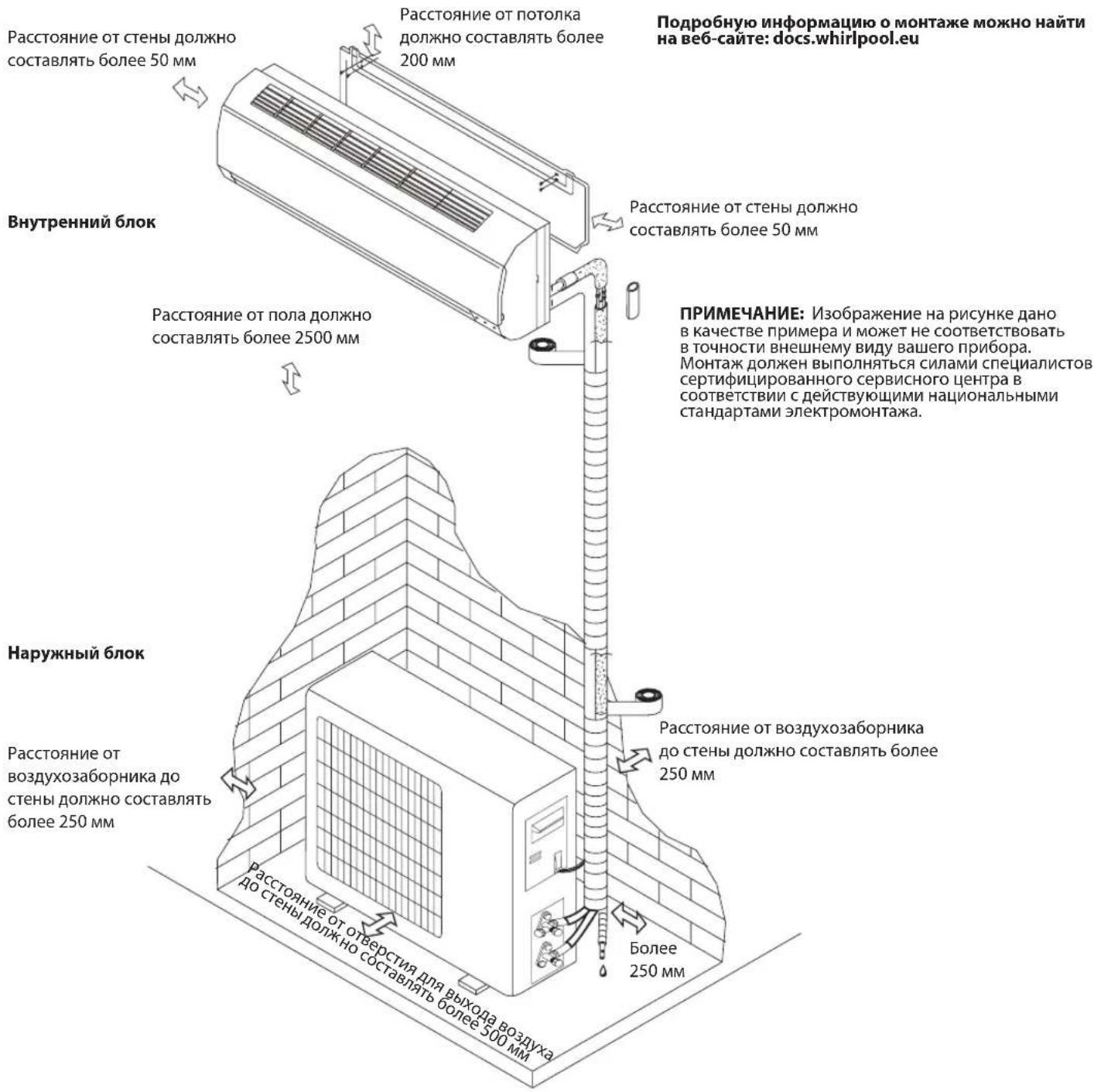
Installation instruction
Installation diagram
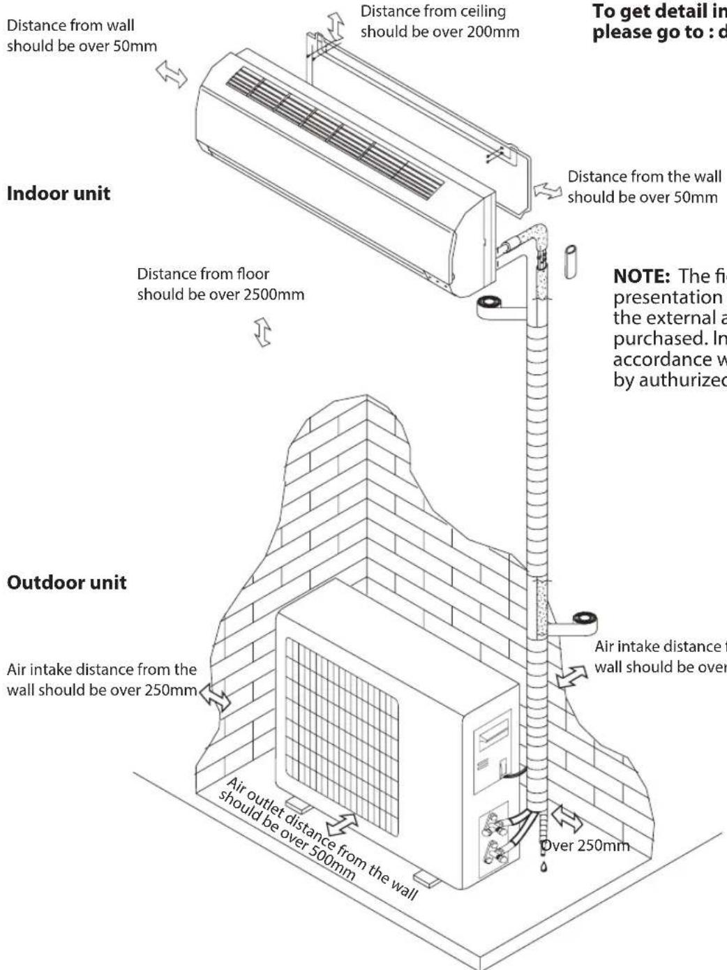
To get detail installation information, please go to : docs.whirlpool.eu
NOTE: The figure is only a simple presentation of the unit, it may not mutch the external appearance of the product you purchased. Installation must be performed in accordance with th national wiring standard by authorized service people only.
When install interconnection cord, make sure that the color of wires and the terminal No. of outdoor unit shall be same as those in indoor unit.
Cable Specifications
| Capacity (Btu/h) | Power cord Power connecting cord | |||
| Type | Normal cross - sectional area | Type | Normal cross - sectional area | |
| 7K, 9K, 12K H07 | RN-F 1.0mm | 2X3 H07 | RN-F 1.0mm | 2X5 |
| 18K H07RN | F 1.5mm | 2X3 H07 | RN-F 1.5mm | 2X5 |
| 24 K H07RN | F 2.5mm | 2X3 H07 | RN-F 2.5mm | 2X5 |
Operation problems are often due to minor causes, please check and refer to the following chart before contacting the service. This may save time and unnecessary expenses.
| Trouble Analysis | |
| Does not run | ·Is the protection device or fuse blown? ·Please wait for 3 minutes and start again, protection device may be preventing unit to work. ·Are the remote control batteries low? ·Is the plug not properly plugged? |
| No cooling or heating air | ·Is the air filter dirty? ·Are the intakes and outlets of the air conditioner blocked? ·Is the temperature set properly? ·Are doors or windows open? |
| Ineffective control | ·Has there been a strong interference (from excessive static electricity discharge, power supply voltage abnormality)? Note that operation will be abnormal, in this case unplug from the power supply and re Plug after 2-3 seconds. |
| Does not operate immediately | ·3 minute delay will occur when changing mode during operation. |
| Peculiar smell | ·This smell may come from another source such as furniture, cigarette etc, which is sucked in the unit and blown out with the air. |
| A sound of running water | ·Normal behaviour caused by the flow of refrigerant in the air conditioner. ·Defrosting sound in heating mode. |
| Cracking sound | ·The sound may be generated by the expansion or contraction of the front panel due to temperature changes. |
| Mist sprays from the outlet | ·Mist is present in the room with low temperature? Normal behaviour due to cool air discharged from indoor unit during COOLING or DRY operation mode. |
| Running indicator flashes but indoor fan stops. | ·The unit is shifting from heating mode to defrost. The indicator will light off and return to heating mode. |
Note: If the problems still have, turn off the appliance and disconnect from power supply, then contact the nearest Whirlpool Authorized Service Center. Do not attempt to move, repair, disassemble, or modify the appliance by yourself.
AFTER SALES SERVICE
Before contacting the Customer Care Centre:
- Try to solve the problem yourself based on the descriptions given in the "Troubleshooting".
- Turn the appliance off and restart it to see if the fault persists.
If after carrying out the above checks, the fault persists, contact the Customer Care Centre.
Please give:
- a short description of the fault;
- the exact model of the air conditioner;
- the service number (this is the number found below the word Service on service sticker which is located on the side or on the bottom of the indoor unit).
- The service number can also be found in the warranty booklet;
- your full address;
- your telephone number.
If repair work has to be carried out, contact the Customer Care Centre (Use of original spare parts and a proper repair is guaranteed).
You will need to present the original invoice. Failure to comply with these instructions could compromise the safety and quality of your product.
SERVICE
0000 000 0000

Note: if you want the full manual for your appliance, please help to download it from website through below link: docs.whirlpool.eu using QR code.

DIESE MÜSSEN DURCHGELESEN UND BEAuchtET WERDEN
Voyant 6th Sense (3)
FONCTIONNEMENT D'URGENCE
6. "6th SENSE"TOETS (TOETS ZESDE ZINTUIG)
7."SWING"-TOETS (ZWENKTOETS)
- "6TH SENSE"-TOETS (TOETS ZESDE ZINTUIG)
7."SWING"-TOETS (ZWENKTOETS)
- "AROUND U"-TOETS (OMGEVINGSTOETS)
3. BOTAO FAN (DE VENTOINHA)
3. BOTAO FAN (DE VENTOINHA)
2. TASTO MODE (MODALITA)
2. TASTO MODE (MODALITA)
6. KNAPPEN 6th SENSE
RENHOLD OG VEDLIKEHOLD
6th Sence indicator (3)
Den tennes nár 6th sense er pa.
Den slukker nár 6th sense slutter.

8.SLEEP (HVILE) KNAPP
8.SLEEP (HVILE) KNAPP
6th SENSE indicator (3)
6. KNAPPEN 6th SENSE
Wskaznik 6th sense (3)
6. PRZYCISK 6th SENSE
4-5. TLACITKO TEMPERATURE (TEPLOTA)
Toto tlacitko slouziknastaveni teploty v mistnosti. Pouziva se k nastaveni casu v rezimu casovace.
6. TLACITKO 6th SENSE
4-5.TLACITKO TEMPERATURE (TEPLOTA)
Indikator fungcie 6th Sense (3)
4-5. TLACIDLO TEPLOTY
Používa sa na volbu teploty v miestnosti.
4-5. TLACIDLO TEPOLOGY
8.SLEEP (ALVAS) GOMB
6-6 OTCYCTBNE NCTOCHNKOB BO3ROPaHNA
B npouecce BbINONHeHn pa6oT, CB3aHHbIX C OTKpbIBaHNem CNCTEmbl Tpy6OpiBOIOB, B KOTOPoI COepeKHTcCeuac IIN COepeXaJcpaHee JERKO BOCpIaMeHJUOniXnaIaIaREHT, CLeIyET N36eRaTb IIO6OTo IcNoJIb3OBaHn INCTOCHNKOB BO3rOpAHn, KOtOpoe MOKeT BbI3BaTb PnCK BO3rOpAHn IIN B3PbIBa. BCE BO3MOxHbIe INCTOCHNK BO3rOpAHn, BKIIoua 3aXkKeHHbIe CnIapeTbI, DOnKHbI HaxOJITbcra Ha IOCTaTOUHOM PaCCTOAHNOT MeCTa MOHTaXa, peMOHTa, DeMOHTaKa I yTuIN3aCUn, TaK KaK B pnoceCe BbINOJIHeHn 3TNx pa6oT BO3MOxHn BbIXoN XlaJaTeHtA B OKpyKaIoUyIO aTMocfepy. Ipeed NaJAmo Pa6oT Heo6xoJIMo OCMOTpeTb pa6oUyIO 3OHY BOKpyr O6OpyIOBaHn I yBeJITbcR B OTCytCBNI NCTOCHNKOB IN PnCKOB BO3rOpAHn. TaKke Heo6xoJIMo pa3MeCTNTb B pa6oueN 3OHe Ta6InuKn "He Kypntb".
6-7HaJIuUeBeHTnJIaun
Ipeen Hauanom pa6oT Ha 06OpydoBaHn, B OcO6eHHocTn pa6oT, CBra3aHHbIX C BBICOKIMN Tempeatypamn, y6eNTecb, YTO pa6o7a 30Ha haoDTca Ha yInue nIN Xopoio
npoBETpNBaeTc.Bo BpeM BbINOpHeHna pa60 CneIyET NOIDepKINBaTb HAnJIeKaUO CTeENb BeHTnJIaCmN. BeHTnJIaCmN DOJXHa OBeCneuNBaTb 6e3OnacHoe paccenBaHne napOB XlaJaTeHtA N, B INDeaJe, OTBeIeHne INX B aTMocΦepy.
| I P E D U N P E X K D E H I E | 3TOT C N M B O L N P O K a 3 b i B a e T, Y T O d a H H b y I P n i b o p I n c n o l b 3 y e T I e r k O B O C N P L A M E H J Y O U S I C R X I N A D A R E H T I, B C L Y U A E Y T E U K I N K O T H A T A X I N A D A R E H T A C B H E U H I M I N C T O U H N K O B O Z R O P A H I N, M O J E T C T A T B I P r i u n H O I N O X J A P A. |
| OCTOPOXH O! | 3TOT C N M B O L Y K a 3 b i B a e T H A H e O 6 x O D I M O C T B B H I M A T E N H O R O I n p o u t e H I N P U K O B O D C T B A I N O E K C P I N Y A T A C I N. |
| OCTOPOXH O! | 3TOT C N M B O L Y K a 3 b i B a e T H A H e O 6 x O D I M O C T B O B P A S I E H I N C O B O P U D O B A H I E M B I P O U C E C E C E P B V I C H O R O O B C L Y U K I N B A H I N B C T P O R O M C O O T B E T C B W I N C P U K O B O D C T B O M I N O M O T H A X Y. |
| OCTOPOXH O! | 3TOT C N M B O L Y K a 3 b i B a e T H A H a I N I Y I N E I N C T O U H N K O B I N H F O P M A C I N, T a K I X K A K P U K O B O D C T B O N O E K C P I N Y A T A C I N I N I P U K O B O D C T B O I N O M O T H A X Y. |
Полбзовамелбckuuhmepfeuc
88
HnDnKaTOp TEMnepaTpyb1(1)
Poka3bIBaet3aHaHHyTo Tempepatyp.
Toka3bBaetFCB KaueCTBe HAnOMHaHnO Heo6XoDMOCn OounCTKn FInbTpa.

HdkaTop Wi-Fi (2)
Bbictpo Muraet (cactoTo3T) npn coeHHeHm cMappyTu3aTopom HIN notepe coeHHeHm C mappyTu3aTopom.
MeiHMO mraet (c aactoTo1,5 T) npn Hauuyn CoeHHeHm C MappTy3aTOpOM nOTcyTCTBn CoeHHeHm c 6bIakom.
TopHT HenpepbIBHO npu yCTaHOBHeHHOM Wi-Fi-coeHNHeHNI.
He ropnt,ecnH cyHKqWi-Fi He HnHnuaHn3npoBaHa nn BbIKIOueHa.

HdkaTop 6th Sence3
TopHT HenpepbIBHO npB BKNIOeHHOM pexKmE 6th sense
He ropnt npn BbIKIOeHHOM pexHme «6th sense>.

HdNKaTOp KOHTpOJa OuNbTpA (4)
Miraet,ecnHne6xOaMoOuHCTNtBnJIbTp.
HnKAtop KOHTpOHa HauHaeT MraTb Yepe3 720 YacOB NcNoIb3ObaHnB KaYeCTBe HaONMaHnO Heo6xOIMOCtN OYCTKN FJIbTpA.
Pocne ouHCTKn HnIbTpna HaxKMITE KONKy c6pOca HnIbTppa, paCNOJoxeHHyHO Ha BHTpeHHem 6nOke 3a nepeHHe nHaHbIO, dI npepbHaHm MraHn INHnKaTopa KOHTpOJIa HnIbTppa.

HdMkaTOp BnaXHoCTn (5)
Topnt npn OTo6paXeHn yPoBHa BnaXHOCTn.
He ropnt npn oTo6paXeHn TempePaTpybl.

HdkaTop TaMepa (6)
TopHT HenpepbIBHO BO BpemHaCTponKn.
BbIKIOaETcnoOKOHuaHIN BpeMeHN paObToI TaMepa.

HdkaTop pa6oerye pexma (6)
TOpHT HenpepbBHO BO BpEm 3KcnIyatauIN.
Miraet BO Bpemy BbIOJIHeHMy OTTaBaNMy HApyXHom 6nKe.

HdukatoppeKMa"HouHou"(8)
BkIouaetcn npn Hactpoe HocHoro pexima. INHdkatop pa6oero pexima mraet 10 pa3, nocne yero Becb dncn BbIKIOucaetc.
Hndkatoppekma"OxnaJeHne
HnDnKaTOp yBEnuHcHnBnAaXHoCTN
HdNkAtOpymeHbWeHnBlaXHOCTN
HndkaToppeKIMa "ToIbKOBeHTNJIaTOp
HdNKaTOppeKMa"OTOnJIeHne"
HnKaTOp yHKun "UnpKnyaUN BO3dyxa
INHdkaTOpfhyKuun"Typ6o"

ABTomatnueckn BbIbOp CKOPoCTN BeHTnTTopa

BbICOKaCkOPOCTBeHTMnTOpTa

CpeHnA cKoPoCTb BEHTNIaTOpA

Hn3kay cKOpocb BeHTnlaTopa

Индikatop ржима"Суретхи"

HnDkaToppeKmMa"HouHou 2"

HndkaToppexmHa"Houho3"

Hndkatop pekmama"Houho4"

INHnKaTOp 3aHaHNoI TempepaTypbI

HndkaTop HacrpoKu TaMepa

IpeepaCnHanoB
HaKMITE KHONKY, BKNHOHTC NOCDBETKa NΦYHKNUOHAJIbHbIe KHONK 6yDyT
aKNTBIVPOBAHbI JnA nCIOJIb3OBAHN.Ⅱn6KnOPOBKNyntBa
HnTACHaUMHO
ynpabHeHHaKmTe
KHOny eue p3.Ecn
B TeeyHe 10 cekHyc
nybTa DnCTAHNOHHO
ynpABHeH He 6ydt
BblONHeHa Hn ODA
onepaun, nyt
6ydt aBtOMaTHueckn
3aOLOKPOBaH.
BeHTnIaTOp"nn "OtOnJIeHHe"
3. KHONKA FAN (BEHTUNIATOPA)
IcnoB3yeTcA DnBb6opaCKopoCTu BEHTnJTAToPA B3aDaHHo
nocneobatebHOCTn:"ABTO,"BbICOKa,"CpeHna"nn"H3Ka"
4-5. KHONKA TEMPERATURE (TEMNEPATyPbI)
IcnoJb3yeTcraBb6opaTeMnepaTypbB NOMeHnn. IcnoJb3yeTcra
HACTPOKIN BpeMeHN B peXIMe TaMepa Ha yacax peaJIbHorO
BpeMeHN.
6. KHOJIKA «6TH SENSE»
YctaHabnBaet nJN OTMeHReT peKm «6th sense»
7.KHONKA SWING (PERYJINPOBKNXAJIIO3N)
IcnoJIb3yeTcA nB BKIOUeHn nn BbIKIOUeHn cyHKuIN
perynilpoBKNIIOJKeHnKaJIOp3N N BbIbopa Tpe6yemoro
HaPpaBHeHnI NOToKa BO3dyxa (BBepx/BHN3).
8. KHONKA SLEEP (PEXKIMA "HOHOU")
NcnoIb3yeTcraBkIIOueHnINnBbIKIOueHnpeXmA《HoHON》B
NOCJIeIOBAteIbHOCTU
9.KHONKA AROUND U (ФУHKUIM "LIPKUYAUR BO3dYXA")
IcnoJb3yeTcA DnB BKIOueHn Nn BbIKIOueHn FyHKuN
Unpkylaun BO3dyxa.
10.KHONKA TIMER ON/CLOCK (BKJIIOUeHn/BBIKJIIOUeHn
TANMEPA)
IcnoJb3yeTc4 nA HaCTpoiKn TeKyUero BpeMeH.
Icnoj3yeTcA nAaKtBaUu Nn DeaKTBaUu BKJIOueHna TaMepa.
11. KHOJIKA TIMER OFF (BbIKJIOUOEHN TAIIMEPA)
IcnoJb3yeTcIy aKTnBaUu IIN DeaAKTnBaUu BbIKIOueHn TaMepa.
- KHONKA JET (ФУнкци "Турбо")
NcnoB3yeTcA nBA BKIOUeHn IIN BbIKIOueHn OyHKUN 6bictporo
OTONJIENI OXNAKDeHnA.
13. KHONKA DIM (PEYUNPOBKN RPKOCTN)
IcnoB3yetyra BkLIOyeHn Nn BbIKIOyeHn NOCBETK DUCNNEA
BHYTpHHeRo 6JIOKa
14. KHONKA POWER SAVE (ФУHKUМ NHEPROCEPEXEHN)
IcnoJb3yeTcA DnB BKIOueHnN NIN BbIKIOueHnOyHKUIM
3Hepeoc6epexehn
15. KHONKA SUPER SILENT (PEXKMA "CYNEPTUXN")
NcnoB3yetyra BkIOUeHn nn BbIKIOUeHn cyneptnxoro peKIma
ДЯ MaKcUmaJIbHO Hn3KOrO ypoBHa Wyma.
CmBONbHa dncnnee nylbTa dntaHOnHOy npabneHn
HnkaToppeKIma"OxnaKeHne
HnDnKaTOppeKIma"OcyuHeHne"
HnDkaTOppeKMa "ToNbkoBENTnIaTOp
IINdkaToppezimMa"OTOnneHne
INHdNkaTop 区 ^ 6 山 SENSE
HnDnKaTOppeKIma"HouHo1"
MnDkaTOp pexkma "Houhoi 2"
HnDnKaTOp pexKmA "HoHoi 3"
HdkaToppeKIMa"HouHo4"
HnKaTOp FyHKuN "UnpkynaB03dyxa
AROMATUNeCKnBbOpe KcOPOCTNBeHTINrTOpa
BbICOKaCKOPOCTb BEHTINJITOPa
CpeHnAckopoCTbBEHTINrToppa
Hn3ka cokopctb BeHTnIaTopa
BnaXHOCTN BbIe 80% B TeueHne DOnrO
BpemeHn, n3 BbInyckHOrO OTBepCTnMoXeT
Haatab Kaatab KOHDeHCAT
Oco6eHHoCTn CNCTembl 3aunNTbl
IpnOCTaHOBKe FyHKUHnPOBaHn
NIN CMeHe peKIma B IpOceCee
fYHKUOHOPOBAHNA BbIXnTe He MeHee
3 MnHyT, npexKe cheM 3aanyCTnb npnbop
NOBTOPOHO. Pn BKNIOUeHn npN6Opa
HeNOCpeDCTBeHHo Nocne NOKJIoueHnK
NCTOuHnky nHTaHnB03MoXHa 3aepkKa
npm.20 ckyH, npexde yem npnbop hauhet
OuNTKa BO3dyHoro fMbTpa
OuNTKa BO3yHOro 0nIbTa DOLJHa npOn3BOUInbCra pnpMeHPO uepe KaKDbie 200 acobkCnnyaTaun. Ecn KOHNIOHep 3KcNpyATpyETcB CUNbHO 3aBnEHHo Cpe, peKOMeHdyTc ONUsAub Bo3DyHbI KINbTp KaKDbie DBe HeJeTI.
1. OToCoeHHeHne OT NCTOCHNka NHTaHn
PepoTcoeHHeHnnpu6paOTNCTouHnKaNTaHnBbIKIOHTeero.
2. ChATne BO3dyuHoro funbtpa (pnc.C).
- OtkpoTe nepeHIO naHeIb. 2. MrgKO HaxMITE Ha pyUky fNtbpa. 3. N3BneKIne Te nIbTp.
3. OuNTKa BO3aYUHOrO fMbTpa (pnc.D)
PnCINbHOM 3arpa3HeHm HnIbTpOaOnCTteero C NMOouTo TELHO pactBopa nn HeITpAIBHO OcTaeero CpeCTBa.
JaTe BbIOxHyTb.
- YctaHOBtpe HnIbTp Ha MeCTo, HaxMIte KhoNkTy c6pOca HnIbTpTa (PNC.E) C npaBoi CTopoHbIC NOMOsbTOHKORO UINHHpueckoro PpeMeTa, a 3aTe M 3aKpOnTe NepeHIO naHeNb.
Приимechли:
- Pocne CHTINB 03dyuHoro fNbTpA He dOtpaunBaNTecb pykAm Do nactnH KaHOn BHTpeHrero 6noka BO u36eKaHne nOyuHn TpaBM.
He nbTaTecb ouHuaTb BHTpeHHIO NOIOCTb KOHNIOHepa camOCToTeNbHO.
He MoTe BO3dUHbI ΦnIbTp B NocydomoeHOn MaunHe.
YNPABJIHEHNE B ABAPINHOI CNTYALINI
B cnyae BO3HKnHOBeHn ABapuHcN CuTyauun nn OTCyTCTBn nybTa nCTaHcHOnHO r ynpabHeHr MOxHO ynpabTb KOHNIOHePOM C NOMOsbU BbIKJUaTeIe BKJIQUeHr/ BbIKIQUeHn, paCNOLOKeHHOrHa BHyTpehem 6Noke.
Bknquhenepn6opae:Ecn npnbop BbIKKoyeh,To npn Haxatm 3ToH KhoNk OH BKnOaetcnaKTINBpye peKIM 6th SENSE.
BbIKNoueHne np6opa: Ecn np6op BKnOueH,To npn Haxattn 30T KhoNk OH nepectaet pa6oTaB.
PnmuemaeHHe HaxmMaTe Ha KhoNky cnnKoM dOnIro Bo n36eKaHne HapyuHnH yHKuOHOpOBaHn.
Функца abTomatnueckoro nepezanycka
Pn Heo6xOaMocTn AKTNBaCmN FyHKmN ABOMaTneCKOro nepe3anyCa BKnOHTe NOaHy NITaHnHa HAKMTe KHOKny BKJI/BblKI Ha BNYtpEHHeM 6IIOke n UyeepKInTe ee B TeueHne 60onee 5 cekynd - FyHKmN ABOMaTneCKOro nepe3anyCa AKTNBnpyETc, B noTBePckJeHne Yero BbIaTeCg KOpOTkn 3ByKOBo CnHaj.
IydeakTbauu yHKun aBtOMaTuueckoro nepe3anycka hAnMnte KhoNkY BKN/BblKn H BAHyTpHem 6JIOke u ydepKnBaTe ee B TeueHne 6oJe 5cekynd - fynKun aBtOMaTuueckoro nepe3anycka deakTbpyetc c KopoTkn 3ByKObIM CnHaJOM, N KOHNIOHep nepexOHT B peXm OxndaHn.
Ytun3aun6atapeek
B cenx coxpanen npnpoDnBx pecypcOB n codeyCTBn BtopnuHoi nepepa6OTke MaepnaIob Co6npaTe Otpa6OtaHHbIe 6atapeKn OTdEbnHOrO O Tpyoro Mycopa N 6ecpNaTHo CdaBaTe IN X B MeCTHbe NyHKtI npnema 6atapeek.
Yka3aHua no Mohmaxy
Cxema MoHTaKa
PnMOHTaKe CoeHNHeBHO Ra6eNaO6paTne Oco6oe BHMaHne Ha COBnaEHe NBeTOB XJI IN KOJIueCTBa KOHTaKToB y HApYxHOro n BHyTppeHrero 6noka.
TexHnueckHe xapaKTePncTnK Ka6eNei
| Емковст (БТЕ/ч) | ШнYP петашия | Соедиителовский kaбель | ||
| Тип | Овьчhoe сеvelпe | Тип | Овьчhoe сеvelпe | |
| 7K, 9K, 12K H07RN | -1,0 MM | 2X3 H07RN | -1,0 MM | 2X5 |
| 18K H07RN-F | 1,5 MM | 2X3 H07RN | -1,5 MM | 2X5 |
| 24 K H07RN-F | 2,5 MM | 2X3 H07RN | -2,5 MM | 2X5 |
Pouck u ycmpaHeue HeucnpaBHocmeu
Pp6nmbi,Bo3nkaoune B npocce 3Kcnnyataun, qacto 6b1BaHOT Bb3BaHbHe3HaHTeBhbIMnpuHNAMPiO3Tomy, npexdyeem obaaatcb C cepBcHcyo cnjx6y, npOBepBe Bo3MOXHy npuHHy no cdeyuoue TaBnue. Ta K bIcmoxKe TcKOHOMtB Bpema n 136kaxtb HeHyxkbix paXoDB.
| ПюбLEMа | Аналз prinчны |
| Пробор не павотает | СравOTANO 3auntHoe uctpoCTBO Или поерopel празoxpaHTeNB? ПолождпгЕЗМБИ ПОпрOBуte BkIbOuHTe PrINbOP cHObA. 3aunTHe Oe uctpoCTBO MOrILO 3a6IokUPOBaTb prinbOp. СelenбатаркВ релытсдТанцIOHORO uPpabLeHINr? Вилka shHypa пNTaHЯ He pOcdoHIneHa nAldKazAm mOBpa3OM? |
| Осустве Notoka ВОЗДУХа в ржIMе oxJaЖденя Или OTONJIENIA | ЗаграЗнен ВОЗДУSHь 的ФИльТ? Засcopeны OTBepCTNДдг 3a6Opa N BvIXOda BOZdYx? ЗадаHA HeHaIEXaAZaJyam TempepaTpya? OTKpbITb DBepri INIgOKha? |
| №эфseKTIVHoe упавлениe | Имел MeTO CERbe3Hoe HApUSeHneФУHKQUHIOHUPOBAHЯ (ИЗ-ЗА СПИКOM CПЛБHORO pa3PRAДA CTATUeCKORO ЗLEKTPUeCCTBa, aHOMaJIbHOrO HAnpRЯЖЕHЯ PITaHЯ)? OTMeTbTe ФakT HApUSeHЯ ФУHKQUHIOHUPOBAHЯ, B ATOM СCitye OTCoEiHNITE BUNKU ShHypa PINTaHЯ OT NCTOCHNka PINTaHЯ I Nepe3 2 - 3 ceKHyDbl NOdCoEiHNITE ChOBa. |
| ЗадерЖа ВыПОЛнEHЯ KMaHД | При ИЗMeHи ржIMa B InpoceSce EKcnPlyaTaZIMMOKeT Bo3HnKaTb 3-MINHyTHa 3aIepjKca. |
| Сtrpanь的一个 | ЭТOT 3aPax MOjtET IcXODIbT b OT dpyrOTo IcTOnHnka, NaPpIMeR, Me6eIi, DbIMa, BCaCbIBaEMoR To PrINbOp IN ВыПуSCaEMLoRTO B OkpUkaIouZIM BOZdYx. |
| ЗвуК ТочЕнЯ BODы | HopMaJIbHoeЯВлЕнe, CBZaHHOe C DVBIXeHmE XlaIaReHtA B KOHDIzIOHepe. ЗвуК OTaINBaHЯ B ржIMe OTONJIENIA. |
| ТrecK | ЭТOT 3ByK MoGTet bItb BvI3BaH paCSWIPeHnE mI IN cKaTnE mpeDeHЯ NaHeli B pe3yIbTaTe KOLe6aHni TempepaTpybl. |
| ВODЯнай Пыль ИЗ BvIXOДHOrO OTBepCTNIA | ВODЯнай Пыль РОВЛЯТСЯ рNi H3Koi TEmpepaType BOZdYx BnomeSEHnI? HopMaJIbHoeЯВlENe, CBZaHHOe C BvIXODOM XOLOHOrO BOZdYx IN3 BvHTpeHnero 6L0ka B pexIMe OXaJxKdeHЯ INI OCUSeHЯ. |
| Индikatop rabochero ржIMa mrigaet, OДнako Bentilaytor BvHTpeHnro 6L0ka He pabotaet. | Прибор пеклUCaETcR ИЗ ржIMa OTOnJIeHЯ Na OTaINBaHЯ. Индikatop ДОЛKEH BvIKIQUHITbCS R IN BepHyTbCS B ржIM OTONJIENIA. |
PnmeH: Ecn np6bmy coxpaHOTcB, BkIOuHTe np6Op, oTOoeHNHe erO tNCTouHka NITaHm H o6paTtEcB 6nnKaun CepTuΦuNPoBAHn cepBnchn ceHPr WhirlpO. He nTaTaeB nepeMeuaTb, pa3bnpaTb, peMOHTuPoBaT uMmoNΦuNPoBA Tb np6Op camoToaRtEnbHO.
ПОСЛЕПОНДАЖНОБСЛУЖИBAHAнE
IpeTeK KaK CBA3aTbCc LcHtPom 06cnykBaHnKJIHeHTOB:
- Nonpo6yIte peuNTb np6JIeMy camocToTebHo, pyKOBoCTByrcb yka3aHnMn B pa3dJe "POnCK n UcTpAnHe HncnPabHOcte".
- BbKIOUHTe N CHOBA BkIOUHTe N3dEJIe, YTO6bl npOBepNTb, He NCue3HeT JIN HeNCpapBHOCTb.
Ecnn nocne npoBeHn yka3aHHbIX Bblwe npoBepok HncnpaBnOCT coxaHreTc, CBxKtEc b CHTpOM 6cbnykBaHn KInHeTbO.
PpeoocTaBbTe cIeNyUOuNe CBeDeHnA:
KpATKOE OINCAHNE HENCPABHOBCTT; TOUHARMOJEnb KOHNIMIOHEpa;
- cepBnCHbH NHomep (Homep, cIeDyUoM nOcNe CNoBa SERVICE Ha Ta6Ntue DaHbIX, paCNOJIOKeHHoH Ha 60KOoB mHnxHei CTOpOnE np6Opa).
CepBnchbHOMep TaKKe yKa3aH B rapaHTnHOM 6yKNeTe;
BaW NOHbI aDpeC;
BaHOMepTeNoHa.
Pn Heo6xOJIMOCTN BblIOJIHeHn peMOHTa 6paauTecb B LcHtp
0cbNyKJBAHN KIneHToB (3To rapaHTnpyET NcNOIb3OBaHHe
OpINHaNbHbIX 3aPuaTeN HaJIeXaUee BblIOJIHeHnpeMOHTa).
Pn ATOM Heo6xOJIMo PpeCTaBtB OpINHaNbHbY Chet.
Hec6NIOJeHne DaHHbIX yKa3AHm MoKeT pINBecTN K
BO3HNKHOBeHn PnCKA HecuactHOro Cnyua N NOBpeXdHn
O6OpyDobAHn.
SERVICE
0000 000 0000

PpmeaHHe: EcnBam HyxHa nonHae Bepcna pykoBocCTBa no 3KcNpyaTauu np6opa, Bb moKeTe 3arpy3ntb ee c Be6-caTa no cnedyuoue cbbInke: docs.whirlpool.eu c nomoob QR-Koda.

ИHCTPYKlIM 3A БE3OПАСHOCT
EДА ГИ ПОЧETЕ И ДА ГИ СПАЗВATE
- I3terIeTe yIIOTo pbKOBoCTBO OT docs.whirlpool.eu nII ne o6aIeTe Ha TeNefoHa, NocOueH B rapaHcNoHHaTa KHNKKa.
- Праздддддддддддддддддддддддддддддддддддддддддддддддддддддддддддддддддддддддддддддддддддддддддддддддддддд徴п
6e3oNaChOCT. Дрьжтгн Ha ydo6Ho macto 3a 6bdeu n cnpaBkn.
B Te3n INHCTpyKcunn Ha Camna ypeI ca npeIcTaBeHN BaxKn npeynpexKeHn 3a 6e3OnacHOCTT, KOInTO Tp8Ba Da ce npOeTaN da ce Cb6IOdaBt BNHaRn. POn3BOdnteJrT OTKa3Ba BCaKaBA OTROBOPHOCT pN HeCnA3BaHe Ha Te3n YKa3aHn 3a 6e3OnacHOCTT, BB BpB3Ka C HeNoDxOJaUa yNoTpe6a Ha ypeDa nn HnPaBnHa NaCTPOkKa Ha OprAHnte 3a ynpabLeHne.
M Horo MaKn Dea (0-3 ro.) Tp6Ba Da cTOrT daneu ot ypeHa. MaKnte dea (3-8 roJ. Tp6Ba Da cToT daJeU OT ypeHa, OCBen Ako He ca NOD NOCTOHNHO H6JIIODeHne. To3N ypeM MoKe Da ce 3NOJ3Ba OT Deua Ha 8 rOnHH N NO-ROJeMN, KaKTO N OT IInca C ORpaHnueHn FIn3NuCeKN, CeINBHN INN YMCtBeHN Bb3MOXHOCTN INN C HeIOCTaTBueH ONIT INO3HaHnra Camo aKO Ca NOD HAD3Op INN Ca NIM DAnEHN IHCTpyKcUN 3a yNoTpe6aTa Ha ypeDa No 6e3OnaceH NaUnn H pa3bnpat Bb3MOxHnTe ONaCHOCtN. DeCaTa He Tp6Ba Da cN iIgparT C ypeDa. NocHTBaHeTo n POndPbXkKaTa OT Notpe6nteJr He Tp6Ba Da ce 13BbpWbAOT Deua 6e3 HAD3Op.
N03BOJEA YNOTPEBA
BHIMAHNE:UpeTHe e npedHa3NaueH da ce n3noJ3Ba C BbHweH taMep nnC OTdJIHa CNCTema C INCTaHcNIOHNOynpaBJeHne.
To3n ypeE npedHa3HaueH 3a ynoTe6a B Domauny ycNoBn I noo6n npinoKeHna, kaTO: XOTeINu Ofncn.
To3n ypei He e npedHa3HaueH 3a npofoecnoHaJHa ynoTpe6a.
BnHa n3KIOUBAIte KINMaTka NbPBO C yCTPOICTBOTO 3a DnCTaHcNOHHO npabHe. He ro n3KIOUBAIte Ha npaboC ppeKbCBaçaHa eNeKTPnuCeKaTa MpeKa nn Upe3 n3BaXdaHe Ha uenCeJa OT KOHTaKa. N3KIOUBAIte KINMaTka OT eNeKTPnuCeKaTaMpeKa, KOrato npoDbJIIXeJIHo HЯMa Da rO n3NoJ3BaTe NnNo BpeMe Ha rpbMOTeBnUHa6ypra.
He BkapBaIte npeMTe B OTBOpNTe 3a N3dyXbaHnB b3dyx - mA ONaCHOCT OT HapaHbAHe. PdIbPkaIte BeHTnlaCIOHHnte OTBOpN Ha ypeDa He3aKpTn.
He noctabrai Te eIekTpoypeu INn IpyrN DOMaKINCKN IpeMeTN NOB BbTpewHOTOn INN BbHNOHO TAn. Kanepa OT TAnOTo KOHNepaB Oda MoKe da rN HAMOKPN IN NobpeDN.
MOHTAK
TobapeheTo,pa3TOBapBaHeTo N MOHTnpaHeTo Ha ypeDa Tp86Ba Da Ce N3BbPWBAT OT DBe INI NOBeue Iuca -IMa ONaCHOCT OT HapaHbAHn. IN3No13BaTe PpeDna3HN pKaBnU 3a pa3ONaKOBaHeTo N MOHTaJa Ha ypeDa -IMa ONaCHOCT OT NOpra3BaHn.
MoHTnpaHTo, BKNIOUHTeJIHO eNEKTPnueCKOTo CBbp3BaHe, INpeMOHTHInTe DeINHOCTN Tp6Ba Da Ce N3BbPbBaT OT KBAIIINΦIuPAH TexHnK CbflaCHO HaUNoHaJIHnTE N3NUCKBaHnK bM eNEKTPnueCKn IHCTaIaIuN. He nonpaBraIte n He 3AmEHNrTe qACTn OT ypeDa, aKO TOBa He e I3PNuHO IOcoUeHO B pBkoBOdCTBOTo HA NOTpe6HTeJ. Pa3eTe DeaTa DaJeu OT MAcTO, KbDeTo Ce N3BbPbBa MOHTaXbT. CneJ KaTo pa3ONAKOBaTe ypeDa, npOBepTe daJIu He e NOBpeDen IO BpeMe Ha TpaHCnOpTnpaHeto. Ppi np6Iemc Ce o6bpHeTe KbM TbProBeca IIIN KbM Hau-6bn3Knra cepBn3 3a CneInpOdaJx6eHo OBCJyXbaHe. CneJ KAto ypeBt 6bJe MOHTnpan, OTnaDbunTe OT ONAKOBkata (PiactMaCa, CTnpOnop n dp.) Tp6Ba Da CToRr DAJeu OT OCerA Ha Deua -IMa ONaCHOCT OT 3aDyShaBaHe. Ppei MoTaxKa ypeBt Tp6Ba Da ce N3KNUOniOT BCNUKn I3TOUHNu Ha 3axpaHBaHe - IMa ONaCHOCT OT eNEKTPnueCKn Udap. PO BpeMe Ha MOHTaxKa BHNmAbai Te ypeBt Da He NOBpeNi 3axpaHbaIg Nk6eI - IMa ONaCHOCT OT eNEKTPnueCKn Udap. AKTNbPaaiTe ypeDa eDBA CneJ 3aBbPbBaHe Ha MOHTaxKa.
ИHCTPYKlIM 3A БE3OПАСHOCT
- ПпrinpemeCTBaHe ИлmoNTupaHe Ha KInMaTnKa Ha Дpyro MЯCTO ce KOHCyItnpaIte C OINTHn CepBn3Hn TexHnCn OTHOCHO DeMOHTaJa I NOBTOpHn MOHTaK Ha ypeDa.
- UpejBt He Tp6Ba Da ce HnCTaInpa B nepaJHo NOMEuHne.
IPEyPExKdEHHBbB Bp3KA C EJEKTPO3AXPAHBAHETO
- UpeBbT Tp6Ba Da ce 3axpaHbC HOMHaHHTO Cn HaPpeKeHne OT camocToTeHeKNOH Ha INCTaIauNraTa.
CeeHneTo Ha 3axpaHbaunia Ka6e Tp86Ba da OTROBapra Ha n3nCKBaHnraTa. - Α Пи посторно CBьрзВань Вьв Берига ТгбВа Да се моHTира MHorОпОЛIOсЕнпpeКьСВач, a урдьт TrяБВа Да се 3a3eMn CnopeДИЗИСКВанЯТа НацИОнAHHITe CTahДapTN 3a eNEKТpo6e3OпаCHOCT.
- Πprn noctoHNO CBbp3BaHe BbB BepnraTa Tp6Ba Da ce MOHTnpa npeKbcBaay 3a BCNUKN pnoBOdHnC mMHmAlHo pa3CToHne MeJy KOHTaKTtTe 3 mm.
He n3no3BaIte ydbJxHnTeJI, pa3KIOHnTeJI C HAKOJIKO rHe3Ja IJIa aIaIaTepNI. CneI MOHTnpaHeTo eJeKTPnueCKnTe KOMNoHEHTn He Tp8Ba Da 6bDaT DOCTbHN 3a Notpe6nTeJI. He n3no3BaIte ypeJa, Korato cTe c MOKpn IJIu 6ocn KpaKa. He n3no3BaIte To3N ypeI, aKO 3axpaHbAunrMy Ka6eI IJIu 7e nceI e NobpeDeH, aKO He pa6OTn npabINHO IJIa aKO e 6NJ NOBpeH IJIu e naIaI.
Ako 3axpaHbauT Ka6e nOBpeDeH, ToT Tp6Ba Da ce CMeHn OT npOn3BODnteJ, HerOB cepBn3eH aReHT nn Lnue C aHaONuHa KBaIINKauN, 3a Da ce n36erHe OnaCha cTuaun, Hapnpem eNeKTpuueckn ydap. - Πпи посторно CBbp3BaHe BbB Берига ТрябВа Да ce MOHTupa yctpoiCTBO 3a ДиференьлнотOKOBа 3aunta C TOK Na CPA6OTbaHe, He NO-rolam OT 30 mA, Kato ce CnA3BaT HaцINOHANHTE HOPMaTINBH N3NCKBaHn.
Tempepatpata Ha xnaiHaTa Bepra MoKe da e BnCOKa; He donyckaTe do npaHe Ha CBbp3Baun Ka6eI DO MeHNHTe Tpb6n.
OcnrypeTe 3aunTHo 3aemBaHe ype3 3aemTeJen HPOBOnHK, CBbp3aH KbM npoecnoHaNo n3nBHeHaTa 3aemTeJHa NHCTanaucna Ha crpaData. YpeBbT Tp86Ba Da ce MOHTnpa C yCTpoIcTBo 3a DeΦeKTHOTOKOBa 3aUHTa, KOMNKeKTOBaHO C N3KJIIOuBaTeJ C NOxODaTOK Ha npEbkIouBaHe. N3KlIOuBaTeJr Tp86Ba CbIo TaKa Da nMa MaHHTHa IN TOPINHHa 3aUHTa, 3a Da npEJa3Ba ypeDa npi KbCo CbeDInHeHne nn IpTeTOBapBaHe.
He cBeTu, KOrato MoDyblT IunCBA nnE n3KJIOueH.

HdkaTop 6th Sense (Wecto yBCTBO) (3)
CBeTn, KOraTo peXmbl 6th Sense e BkIIOueH.
Yracba, Korato 6th Sense npuknou.

HndkaTop 3a cbctOarHeTo Ha hntbpa (4)
Mura, KoraTo fntbpbT Tp6Ba da ce noHCTn.
HINIKAToPb3a CbCToHnEto Ha 0ntbpa 3anoYba da mra cne7 720 pa6OTn Yaca, 3a da HAnOMHN, ye e Heo6xOJMo FInTbpT da ce. NocHTy.
Korato nouCTnte fHNTbpa, HATNCHEte pa3noJoxeHna Ha BbtpseHOTo TAn 6yToH 3a Hnuaan3npaHe Ha HndkaTopa, 3a da N3KnOHTe Muraun CnHaJ.

INdikKaTOp 3a BnaxHoCT (5)
CBeTn, KOraTo DNcNneT NOKa3Ba CToHOCCTTa Ha BJaXHOCTTa.
He cBETn, Korato dncnnert noka3Ba TemnepaTypaTa.

HdkaTop Ha TaMepa (6)
CBeTn npe3 3aadeneHnepno
YracBa npn n3TuHa He npnoHa Ha TaMepa.

Hdukatop 3a BknoeHo cboTnne (6)
CBETN, KORATO ypeBbT pa60TN.
Mura no Bpeme Ha npoueypaTa 3a o6e3ckpeXaBaHe Ha BbHnHOTo TJIIO.

HnkaTop Ha pexkma 3acbH (8)
CBETBA npn BkIIOUBaHe Ha pexKIma 3a CbH. INHdkATOpbT 3a BKIOUeHO CbCTOARHe npmMIRBa Decet NtN, CneI KOEtO cENrT DnCnIeYraCBA.
YcmpoUcM8O 3a duCmaHcuOHNo ynpabJeHue
NoctabrayeHa6aTePmNBycTpoiCTBOTO3a
dntaHnOHNoynpaBneHne
- BkapaTe TneB O TbOpa, Neko HauChHe TaHbTpke KaNaKtA Ha OTdeneHnTo 3a 6aTePIne Iu N36yTaTne NO nOcOKa Ha CTpeNkata (Bk.ΦnYDpa), 3a Ja N3BaJNTe.
- IocTabe 2 6pO 6aTeepn fOpMaT AAA (1,5V) B OTenEnHneTo. BHIMabaTe 3a Cna3BaHe Ha O3HaueHATA NOJPHoCT ^+ "N
- 3aTbOpTe KaNaKhKaTa Ha OTdeneHneTo 3a 6aTePnnte Ha yCTpOINCTBOTO 3a INCTaHcUOnHO ynpabNeHne.
Hauanho cboemnue Ha ycmpoucmbomo 3a ducmahuonho ynpaehenue
PnBcKa CMHa H6atepnte NIN PpeKbCBAHe N B3ctaHOBBaHE Ha 3axpaHbAteHO Ha yCTpoiCTBOTo 3a DuctaHNOy npabIeHne To ce yCTaHOBaHBe pexkIma 3oTOnJIHne; AOKa3kyNEHrT KIMMaTNI MOKeJa pa6OTn Camo B peXmHa OxJAAJaHe, TO3N pEXM He pa6OTn HO MoKeJa ca eNIOJ3Ba CbIoTO yCTPOICTBO 3a DnCTAHIOHOYnpaBNeHme.
I3noJ3BaHe Ha yCTpoJCTBOTO 3a
DnCTaHUNHO ynpabHeHa KInMaTnKa
3a KOHTpOJIuPaHe Ha KINMaTHKa Upe3 yCTPOIcTBOTo 3a DnCTaHnIOHNOYnpAIBeHne TpABBa Da HAcOHTe YCTPOIcTBOTO KbM npEmMHNkA BbB BbTpeHOTo TAn, 3a Da OcIrpyPte npEmHa He CNrHnA.
- Pn IN3npaHe Ha CnHAn OT yCtpoIcTBOTo CNBONbT Mmra B npOdbJnxKeHne Ha 1 cekyHa. Pn nOnyuaBaHe Ha CnHana YpeDbT n3daba 3ByKO BnHAn.
- UcTpoIcTBOTMOXe Da ynpaBnBa KInMaTnKa OT pa3CTOHaHne Do 7 MeTpa.
- PnBcKa CmHa Ha 6aTePnIe yCTpOINCTBOTo 3a INCTaHcNOHNOynpaBHeHne ce yCTaHOBBBa B pexM 3a OTONJIeHne.
3a6eJkKa:OT npBedeHnTe No-dony yka3aHnCna3BaIte Te3N, KOInTo ca npedHa3HaueHn 3a MoEJa Ha yCTpOiCTBOTO, C KoETo e DOCTaBeH 3aKynHeHnT OT BAC KInMaTHK.
fHyKnMOHaHn OINCAHn He 6yTOHnTE (P1-03)
1. BYTOH 3A ON/OFF (BKJIIOUBAHE IN N3KJIIOUBAHE)
Upe3 HaTtCKaHe Ha 6yToHa ypeBt Ce BkIIOuBaN M3KIOUBA.
3.5yTOH 3A FAN (BEHTINATOPA)
M3nON3Ba ce 3a npomHa Ha ckopoCTHa HBeHTInaTOpA B CJIeDNHn peD: ABTOMaTHNHO, BWCOKA, CPEDHa, HMCKA.
4-5. BYTOH N3 TEMPERATURE (3A TEMINEPATYPATA)
H3non3BaTe 3a 3aabaHe Ha TemnepaTypaT B CTaTa.
B pexim C taImepe Ce n3nON3BaT 3a 3aDaBAHe Ha BPEMTO
6. BYTOH 6th SENSE
BkIIOyBaN N3KIOyBapeXIM 6th Sense.
- BYTOH 3A SWING (ДВИХЕНUE HA CTPYRTA)
CnnpaNINBKNIOVA BbPTeHETo Ha xOpHOTAHJIHNTe HAcOHaBuaKJAny3n 3aDaBA NOcOKaTAt Ha Bb3DyUHNIH NTOK (Harope-HaONy).
10-11. BYTOHN3A HUMIDITY (BIAXHOCTTA)
I3noJ3BaT Ce 3a3daBaHe Ha BnaJxHOCTTa.
Pa60rT cmoB pexim 6th Sense.
Cekynd He Hatriche EHTOYVCTPOCTO
- BACTHUMOHNG
SdAeTaeHnONVNDABNEHNE C

HnKAtop 3a pexkM 3a OTonneHne

Hnka ckopocHa BeHTnNaTopa

HnKaTOp 3a peKIM 3a cbH 4
yipubncc
SAHACHOTE BTOHA

UHdkaTop Around U HdkaTop 6

B. senescence

INHdkaTOp 3a3aJaEHaTa TempePaTypa
EKDaHbT CBeTBa
NΦVHKUNOHAHHTE
BvToHn 11e 6

HInkaTOp 3a jeKmHa 3a 6b3oOxJaKaHe NJI 3aT0panJa

INHINKATOp 3a INKOHMOUeH peKIM

HdkaTOp 3a n3MbBaHe Ha CnHan
AKTNBHN 3a
M30138aHe
Ycmpoicm80 3a ducmaHcuOHn ynpabJeHue
Функионанно описнане на 6утонITE(J1-3A)
1. BYTOH 3A ON/OFF (BKJIIOYBAHE N U3KJIIOYBAHE)
Upe3HaTnCKaHe Ha 6yToHa ypeBt Ce BKNIOuBa Nn3KNIQUBa.
2.6YTOH 3A MODE (PEKIMHA PA6OTA)
U3non3BaCe 3a 3aDaBaHe Ha pexkmaHa paobota B cneHnpei OxnaJaHe, HamaJbAHe Ha BnaxHoCTTa, BeHTnlau, OToNnEHe.
- BYTOH 3A FAN (BEHTNIATOPA)
H3nON3Ba ce 3a npOMHa Na CKOpOCTHa BA BeHTIaTopa B CneIDn peD; ABOTMaTHUHO, BWCOKA, CpeDA, HNCKa.
4-5. BYTOHN 3A TEMPERATURE (TEMNEPATYPATA)
H3no3BaT ce 3a 3daBaHe Ha TempePaTaB cTaTa. B pexM C TaMep Ce H3no3BaT 3a 3daBaHe Ha BpemeTo. H3no3BaT ce n npC CBepBaHa He yacOBnHa.
- BYTOH 6th SENSE
BkIIOUyBa Nn3KIOUoyBa peXm 6th Sense.
- BYTOH 3A SWING (ДВИЖЕНЕ HA CTPYRTA)
CnnpaNNBkIOUBa BbPteHETo HaXOpN3OHTaHHTe HAcOyBaUNKany3N 3aDaBa NocOKaTa Ha Bb3dyuHnIPOTOK (Harope-HaOny).
- BYTOH 3A SLEEP (PEXNMA 3A CbH)
IpeBknOuBa Mekdy peKmUTe 3a CbH NII IN3KnIOyBa TO3n peKIm. 9.BYTOH AROUND U
I3non3Ba ce 3a BKNIOUBAHe I N3KIOUBAHe Ha fYHKUNrTa Around U. 10.BYTOH 3A TIMER ON/CLOCK (YACA HA BKIOUBAHE INJIM 3A CBEPRABE HA YACOBHKA)
N3nON3Ba Ce 3a CBepeBaHe Ha YacOBHnKa.
H3n03Ba ce 3a 3aabaBe nIe OTMaHa Na cHa a BKNIOUBAHe Ha ypeA. 11. BYTOH 3ATIMER OFF (YACA HA N3KJIIOUBAHE)
H3nON3Ba Ce 3a 3aDaBaHe IJN OTMaHa Na YacHa N3KJIIOUBaHa Hyaypeda.
- BYTOH 3A JET (БьрзО OXЛАЖДАНЕ ИЛN 3ATОПЯНЕ)
V3non3BaCe 3a BkIIOUBaHe N3KIIIOUBaHe Ha φyHKUraTa 3a 6bp30 OxJAAHe UIN 3aTOnJIHe.
13. ByTOH 3A DIM (BKJIIOUBAHE N N3KJIIOUBAHE HA DNCNIE)
H3nOJ3Ba Ce 3a BkIIOUBaHe nN3KIOUBaHE Ha DnCPIeHa BbTpEwHOT TAno.
14. BYTOH 3A POWER SAVE (IKOOHOMUHEH PEXKUM)
I3nOJI3Ba Ce 3a BkIIOUBaHe I N3KJIIOUBaHE Ha IKOHOMUHINRApeJIMHa daB07a.
15. BYTOH 3A SUPER SILENT (CBPbXTNX PEXKIM)
N3NON3Ba Ce 3a BKIOUBAHe N3KIOUBAHe Ha CBpBxTnxnpeXIM CMHORO HNCKO HNOHa Wyma.
CnmbonHaekpHaHa yctpoCTBOTO 3a dntaHouHOynpAbeHne

HINIKATOP3apeKIMHaOxNkDaHe

INHnKATOP3apeKIM3a CbH1

ABTOMaTHO perynlpahe H cKOPOrHbA heBHTINatopota

INHnkaTOp 3a peKmHa 3a 6b3o oxnaXaHeA NIe 3atOnPJIae

INHINKASTOP 3paEzhmka 3a HAmJAABaHE NaBxAKHOCTA

INHnKatop3apeKIM3acbh2

BvCoka ckopost Ha BEHTUNATOPA

HINKATOP3aN3bVbHeHaCNrHan

HINDKaTOp 3a pejkm Ha BENTMaZuHa

HnDnKAtOp 3a peXmM 3acbH 3

CpeHaCKOPOCTHaBEHTWATOPa

HdNkaTOp Ha YacOBHnKa

VHdNkAtop 3apeKIM 3aOToTnIeHHe

HnKaTOp 3apeXMM 3a CbH4

Hncka ckopocHa BeHTnataTopa

HdkaTOp 3a NkOHmUeH peKIM

HdNkaTop 6th Sense

UHdkaTop Around U

INHdkatop3aCBpbxtnxpexnn

HdkaTop3aNKoHOMuH peKIM
3ALUNTA
YcnoBnaHa pa6oTa
3aunTHOTO yCTPOCTBO MOKe Da cpa60TN N da Cnpe paoTata Ha ypea B NocoueHNTe No-dony cnuyan.
Indicator 6th Sense (3)
Se aprinde cand este activata functia 6th Sense. Se stinge cand estedezactivata functia 6th Sense.

6. BUTONUL FUNCTIEI 6th SENSE
2. BUTONUL MODE (DE MOD)
Se utilizeazea pentru a selecta modul de fonctionare.Modurile de fonctionaresunt, in ordine, Racire, Incalzire sau Ventilare.
8. BUTONUL SLEEP (MODULUI DE VEGHE)
Seutilizeaza pentru a selecta modul de veghe in ordinea Mod de veghe 1, Mod de veghe 2, Mod de veghe 3, Mod de veghe 4 si Mod de veghe oprit.
9. BUTONUL FUNCTHEI AROUND U
2. BUTONUL MODE (DE MOD)
Seutilizeaza pentru a selecta modul de functiOnare in ordinea Racire, Uscare, Numai ventilare sau Incalzire.
3. BUTONUL FAN (VENTILATORULUI)
6. BUTONUL FUNCTIEI 6th SENSE
Seutilizeaza pourtau setarea sau anulareafunctiei 6th Sense.
7. BUTONUL SWING (DE OSCILARE)
Opreşse sau莅cepe oscilarea fantei de reqlare pe orontalà.si
seteazà directia dorita a fluxului de aer, in sus sau in jos.
8. BUTONUL SLEEP (MODULUI DE VEGHE)
Seateaza sau anuleaza modul de veghe in ordinea indicata.
9. BUTONUL FUNCTEI AROUND U
Seutilizeaza的特点a seta saua anula functia Around U.
10. BUTONUL TIMER ON/CLOCK (DE PORNIRE A
TEMPORIZATORULUI/CEASULUI)
-ПepeKoHaITeCb,ио DeTeKTop He ε NOTeHciHm IxpeJom 3aMHaHHi nIXOuNTbДЯ BnKOpNCTOByBaHOrO XOJIoDoaReHTy.
-
06naHaHHaIy BnAByHHeHHaBTOKIB cIiHaCTpoIOBaTu y BiDCOTkax BiL FFL xOonoareHTy i KaJIbpyBaTn Iy BnKOpNCTOBaYBaHO XoNoOaReHTa, a TAKOX NiITBepDxKyBaTu BiNObiHni BiDCOTOK ra3y (MaKcIMMym 25%).
-
PidHn DnBnBHeHH BnTOKiB npuaTHI nBnKOpncTaHH 3 6iNbwiCtIO XoNoOaReHTiB, OHaK CnId yHnKaTn BnKOpncTaHH MIOUChX 3acO6iB, IIO MiCTaTB XLOp, OCKInbKN XLOp MoKe B3aEMODiTn 3 XoNoOaReHTOM i BnKInKaTn KOp03IO Tpy6OpnpOBOn 3MiDi.
-
Y pa3i nio3pn Ha Bntikannr Ra3y Heo6xidno npn6paTn/3aracntn BiDkPnte noJyM'
-
Y pa3i BnBnEnHn Micu BnTOky XoJIOaReHTa,Ke NOTpe6yE naHHn, BeCb XoJIOaReHT CnId BnIyUnTI 3 CNCTeMn a60 i3OJIbAtn (3a DOnOMoroIO 3anO6IXKnaPaHIB) B uactNI Hi CNCTeMn, B kIK He BiD6yBaCTbcra BNTiKaHHN.
-
Пара ТКOM I B npocci BnKoHaHЯ NaKn Heo6xIDHO npokaTu a3OT 6e3 DomiHKN KncHIO (OFN) uepe3 cnCTemy.
12.BuJaIeHHI BnOpOxHeHH
- Pnpo3pmbaHHI KOHTpy XOJIOaReHtA DnI npOBedeHHpeMOHTHX p06IT a6O dIg 3 Bydb-RAKOIO IHsOIO MeTOIO CnID 3aCTOCOByBaTn 3BnuAai Hi npOeDypn. Ondak BaxKnBO BIKOPNCOTOByBaTn Cyuachi eΦeKTHBHi MeToDN, OCKINk 3aBxDn € aKTyalbHOIO BOrHeHe6e3neKa.
DotpmyTecbHaCTynHOI npOceDypn:
-Binnyutb xolonoarent;
- PódyuTe KOHTyp iHeptHnM rA3OM;
-BunopoxhHiTb KOHtyp;
- 3HOBy npOdyuTe KOHTyp IHePTHM rA3OM;
- P03ipBtB KOHTyp shnXom pi3aHHa6o naHHa.
3a npabKa xolonoareHa Mae 6ytu 3diIcHepa y BiIDnoBidiHi BiIDHOBIbAblHi 6aIohn. CnCTemy Heo6xIDHO «npouHCTHTU» 3 BVKOpNCtAHm OFN, 0o6 3a6e3neuHTn 6e3neue H BVKOpNCtAHn npicTpOIO. MoKlNbO ue npocec nOtpi6Ho 6ytu BVKOHAtn KInbKa pa3iB. IJra BVKOHHH
IHCTPYKLII 3 TEXHIKU BE3NEKN
ciie npoeedyn He cnd BnKOpNCTOByBaTn CTncHe NOBITpy KInCeHb. IpOunueHHa CId BnKohyBaTN 7JxOM P03PnBaHH KOHTpy dny Ioro 3aIOBHeHH, NOKn He 6yde DoCgrHytn Poobouh Tnck, NotIM BnPyCKaHH B aTMocepy i, HapeuTi, BNTryBaHH DO DoCgrHeHH BaKyUMy. LcE npoec cnd nOBTOBAtn, NOKN B CNCTemI He 3aIIuHTbcg XoIoDoareHTy. Ppi 3diNCHEHHi KInCeBOrO 3aNPabJIeHH CnCTEmY Cnd BnNOPoxHNr Dny DoCgrHeHH 3HaueHb aTMocepHOrO TnCKy, Uo6 3a6e3neuHTn FyHKQIOHyBaHH KOHTpy. Lz Onpaizr E 6e3ymOBHO Heo6XiHDHO y pa3i BnKoHaHH Onpaui NaHnnr Tpy6onpoBODy. PepeKoHaITeCb, 10 BnPyCKHm OTBip BaKyUMHO HaCOca He 3NaXoDnTbcr NObNI3y 6yd-RAkHex JKepe9 3aImaHH i B cnCTeml OFN 3a6e3neueHm BaKyU m i 6e3nepePBHa BeHTnlaizir.
INdkaTop TemnepaTpyn (1)
Biodobpaxka BcTaHOBNeHy TempepaTypy.
KoHn notpioHO ouHCTHTn fIbTp, Ha HbOMy 3'RbIeTbcra IHNkaiaf
IIndkaTop MepeksiWi-Fi (2)
BIn 6nMa e (3 T) nic nikKIOeHHo MappyTu3aTopa a60 KOIN BTPaay 3B'3OK 3MappyTu3aTopom.
BIn nobinbHo 6nMa€ (1,5 T), KOni niknloueHm do MapwpyTu3aTopa, ane He niknloueHm do xMapn.
IHdkaTOp NoCTiHOCBITnTBcR, KOJI NiWi-Fi NOBHicTIO NIDKIOUeHO.
BIN BUMKaeTbcR, KOJI Ni Wi-Fi He HanaTObaHO a6o BIMKHeHO.
INdkaTop 6th Sence (3)
BMkaetbca, kuo 6th sense yBIMKHeHO.
BmMkaeTbca, kkuo 6th sense BmKHeHO.
IIndkaTop KOHTponIO fInbTpa (4)
Bnmae, KOH NOTpi6HO OuNCTTN fInbtp.
IHNKaTOp KOHTpOIO fIbTa 6JImae nicra 720 roDn H BkOpncTahHЯ KHarayBaHHN pno Heo6xIDHcTB oUneHHa IInbTpA.
Iicra ouiueHHa Htba KONky cKaHnaHH iJbtpa, po3aowobHy h BHTpiHbomy 6noci 3a nepeHbOIO naHennIO, o6 npnnHHTn 6nMaHH iHdkaTopa KOHTpOIO foJbtpa.
IIndkaTop Bolorocti (5)
BIn cBITbcra, KOIN BIO6paKaetbca pIbeH Bonorocti.
BIn 3rae, KOIN BINO6paKaεTbcr TemnepaTypa.
INdkaTop TaMepa (6)
BIn Cbitntbcn Ha npotra BCTaHOHeHOrO yacy.
Bin 3raacé, konn di TaHmepa 3akHcyETbcra.
IHdkaTop yHKuiohyBaHHa (6)
Bin cbiitbcra niacp06oT npuna.
BIn 6nmae npn po3mOpoxyBaHHi 3OBHsiHbOro 6NoKy.
IHHkaTop pexmy oukyBaHHa (8)
Bih CbITbCn BCTaHOBHeHH pexmmy OuykBaHH, HdkaTOp yHKioHyBaHH 6nMHe 10 pa3, nCn yoro Becnne 3rache.
BcTaHOBHeHHa6o cKacyBaHHpO60Tu 6th sense.
BUKOPINCTOBYETcIyIYBIMKHeHHa 60BIMKHeHHN1iNCbIyUBaHHN DnCnJIe HaBHTpiHbOMy 6NoI.
14. KHONKA WI-FL
BukopncObyeTbcn yBIMKHeHHa N BmKHeHHa Wi-Fi.
15. KHONKA «TIMER» (TAUMEP)
BnKOpNCTOByeTbCnI BCTaHOBHeHHaCy yBIMKHeHHa 60 BmKHeHH npJaNy.
CnmbonHa dncnnieynbty ducntaHIOKepyBaHH

HINKATOPOXIOJXeHHA

ABTomaTHHnpeKIMBCTAHOBHeHH HwNkOCTI BEHTnTATopa

IHdkaTOp pekmU oyikybaHHr 1

IIndkaTop 36inbweHnBONorocti
Bucoka wbndkictb BHTnIaTopa

IhdkaToppeKmyOikyBaHH2

IINKATOP3MeHWeHHBONOROCT
CepdHbWbNkictBBeHTnIaTopa

IIndikaTop pekmmy oukybaHna 3

IHINKATOPYBIMKHEHHIINBEHTNIATopa

Hn3bka WbNdkicTb BENTINrAToPa

Indikatop pexn My OiyBaHn4

Hdikatop HarpibaHH

IHdkatop6e3wymHOi p6oTn

BIO6paXeHHB BCTaHOBneHoi TEMpePaTyPi

IHnKaTOp fHyKuii Around U H

6 SENSE

DcnnneBCTaHOBNEHOrTo TaIMepe

IHdkatopfynKuJi

BctaHOBHeHH a6o ckacyBaHH po60tn 6th sense.
BukopncTOBycTbCnBCTAHOBNEHnNTOOHTHOcAcy. BukopncTOBycTbCnBCTAHOBNEHnAboCKacyBaHHOnepaJIYBMKHNHe TaIMePA.
11 KHONKA TIMER OFF (BUMKHEHHA TAIIMEPA)
BukopncToBycTcIy BCTaHOBHeHH a6o cKacyBaHH onepaii BUMKHeHH TaMepa.
- KHONKA PEXKUMY «JET»
BukopncOByeTbcraI3anycky a6o npnHHeHHpeKIMy WbnKoro OxonoJKeHHa6o HarpibaHH.
- KHONKA «DIM»
BukopncTObyEbCnIy yBIMKHeHHa6o BUMKHeHHn iDcBiYBaHHn DnCnner Ha BHTpiHbOMy 6noqi.
- KHONKA «POWERSAVE» (EHEPTO3BPEXEHH)
BukopncToByeTbcaIra3ayncky a6o 3ynHKnpeKmyehepro36epkeHHn.
- KHONKA PEXKMY «SUPER SILENT» (BE3WUMHA POBOTA)
BnKOpNCTOBycTbCnIaNcycky a6o 3ynHKnpeKmMy 6e3WymHoi pO60Tu 3 Hn3bKmPIBHem WymiB.
CnmbonHa dncnnei nynbty ductaHIOKepyBaHHA

Hdkatop oxoJxehn

IДиКаTOp pexmmy ouikyBaHHa 1

ABTOMaTHHmpeKHM BCTaHOBHeHHbWbDKoCTI BEHTNATOPa

IHdkaTOp fynkui «Jet

IzhinkatopФункшьсучывань

IINKATOP pekmmy oukyBaHHN 2

BnCoka wBnDkiCtB BeHTnIaTopa

Ipeepa cunHany

IHINKATOp yBIMKHeHHNJIuWe BHTNITOPa

IДикатop pexmy ouikybaHHa 3

CepenHbWbNkictb BHTnTota

A. 100% of the time

HdNkaTop HarpibaHHa

IДИКATOP pexmmy ouikyBaHnA 4

Hn3bKa WbUdkiCtB BeHTnIaTota

Biodobpaekenna notouhoroacy

IIndikatop 6h Sense

IInkataOp yHKuII «Around U

INdkaTop6e3wymHoIpo6oTn

Biodo6paJHNNBACTaHOBnHOI Tempepatpy

IIndukatop ehepro36epexhenn
3AXNCT
yMOBn3aCTocyBaHHr
3axnCHn npnCTpi moKe 6yTN 3ynHnTI BmKNHTn pnnla y BNpaKkax,HaBeJeHN HnKHe.
Texhivhe 06cny2oBybHaHn
OuueHHnpeepHb0i naHeni BHyTpuiHb0r6Ioky
1. BiD'eHaHHB BiD dKepepea KnBneHHA
CnoaTky BmKHTb npuia, a notim Biiknouitb Bi dJkepea KnuBneHra.
2.3Himannnnepehboi nahei
BikpnTe nepeHIO nHaHb, kN oKa3aHO cTpinKIO (MaI. A).
I3 ycnlln m notarHt b 3 na3 60kIB nepenhboi nanei, o6B BntrHytn nepedno naneb (Ma1. B).
3. Ouichienna nepedhboi nahei
Ipopttb II Hacyo M'aKOIO raHupKOIO. RaIO npuiaD yJx 3a6pydHeHn, BIKOPcTObyTe dIra OunueHHa TeybOy (3 TempepaTPOIO HnxJc 40°C). Picra OUnueHH cIa npocuyttn NaHeB.
4. YctaHOBHeHHI 3aKpNBaHnnepeHbOi naHeJI
BctaHOIBtHaMicIe 3aKpNItepeDnIO NaHeb,HaTcKaOuN II DOHNy.
PpMItKa:
He BnKOpuctOByTe dIra OunuHn npuaTyaki peoBuHn, k6eH3nA 60 wIiOyBaIbHn nopouok.
- He po36pns3kyTe Body Ha BnyTp1uHn 6nok. Lc He6e3neuHO! Lc MoKe npu3BecTu Do ypaKeHHa enektpnuHm cTpyMOM!
OuueHHH noBITpHoro foIbtpy
NobipraHHn fihbtp notpi6HO nCTHTN nicna Noro BHKOpuctaHn npTcrom np6n3Ho 200 roHN. RaKoHnuciohe npauoe B Hnd3Bnuayho 3aannneHomy cepedOBu, ouuuyte nobipraHHn fihbtp kOxHi Dba TnxHi.
1. BiD'cHaHHB iD dKepeJa KnBneHHA
Cnoaatky BmKHTb npuaad, a notIM BiKIOuHb Bi dJkepeNa JnBHeHH.
2. BuTaryBaHHNoBITpHOro fInbTp(a man.C).
- Bɪdʌpɪnɪte nepeɪdɪŋ næhɪb. 2. OɒbɛpɛɡHo Ḥaɪnchɪtɪb Ha φɪkcaTOp φɪnbTpa. 3. BɪcʊhʌTe φɪnbTp.
3. OuHHeHH NoBipraHoro fInbTp a (MaI.D)
Akyo fIbTp nyke 6pydHn, ouHCTiB yoro po3yHOM HeuTpaHOro MNoOoro 3acOby B TeNlI BOJI. Picra ouHsEHHa cnid npocuyHTn naHeB.
4.ДЯВCTAHOBHeHHHФINbTpHaTnCHITbHa KONkyIЯ NOBtOHO BCTaHOJIeHHHФINbTp(aM.N.E)3 npaboi cTOpOH 3a DonomorHO cnInHpUHOro WTHΦaI 3akpnTe nepdHIO naHb.
Pnmuitka:
- ⅢO6 yHnKHyTn TpaBm, nicra BuaIeHHa fInbtpy He TopkaiTeCn nactn HByTpuihboro 6nOKy naIbqMn.
Hehamaratae camocitno OuyuBn BHytpiHIO acTHNY KOHNIOhepa.
He ouuynTe fInbTp B npalbni MaunHi.
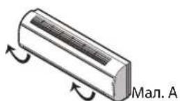
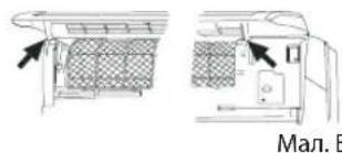
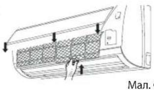
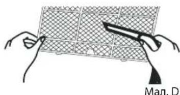
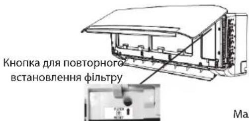
ABAPIHIM PEXKIM
y Bnnaiky aBapiniHoi cntyaui 60 y pa3i BiicytHOCTI nyltTy nictaHIO HO KepyBaHHa MOxHa KepyBaTN npNCTPOEM, HATNCKAOHN nepemKau yBIMKHeHH/BNMKeHHa, PO3TaioBAHn Ha BHTpiHbOMy 6noi.
- YbIMKHeHHn npnilaNy: kkuo npncptpi BmKHeHn,HaTCHiB zu KhoNky, npncptpi 3anyctntbcra i 6yde npauBoTaB n peXmI «6th SENSE».
BumKHeHH npnay: kIoo npncptpi ybIMKHeHn,HaTNCHTb 10 KhoNky, npncptpi npnnnHtbp6Oty.
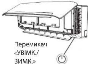

- PERMITTED USE
- INSTALLATION
- SAFETYINSTRUCTIONS
- ELECTRICALWARNINGS
- CLEANING AND MAINTENANCE
- DISPOSAL OF PACKAGING MATERIALS
- DISPOSAL OF HOUSEHOLD APPLIANCES
- DECLARATIONS OF CONFORMITY
- SAFETY INSTRUCTIONS FOR SERVICING APPLIANCE WITH SPESIFIC REFRIGERANT
- Charging procedures
- 14.Decommissioning
- 15.Labelling
- 16.Recovery
- Product description
- Temperature indicator (1)
- Wi-Fi indicator (2)
- 6th Sence indicator (3)
- Filter monitor indicator (4)
- Humidity indicator (5)
- Timer indicator (6)
- Running indicator (6)
- Sleep indicator (8)
- Insert the batteries into RC
- - Remote Control presetting
- Use RC to control the appliance
- Function description of buttons (P1-03)
- ON/OFF BUTTON
- 3.FAN BUTTON
- 4-5. TEMPERATURE BUTTON
- 6.6th SENSE BUTTON
- SWING BUTTON
- 10-11. HUMIDITY BUTTON
- SUPER SILENT BUTTON
- MODE BUTTON
- 8.SLEEP BUTTON
- 9.AROUNDUBBUTTON
- 12.JET BUTTON
- 13.DIM BUTTON
- 14.WI-FIBUTTON
- 15TIMER BUTTON
- Symbols on RC display Active RC by pressing UNLOCK button
- Function description of buttons (J1-3A)
- FAN BUTTON
- TH SENSE BUTTON
- 7.SWING BUTTON
- AROUND U BUTTON
- TIMER ON/CLOCK BUTTON
- TIMER OFF BUTTON
- DIM BUTTON
- SUPER SILENT BUTTON
- Symbols on RC display
- PROTECTION
- Operating condition
- Features of protection device
- Features of COOLING mode Anti-freezing
- Features of HEATING mode Preheating
- Defrosting
- Clean front panel of Indoor Unit
- Note:
- Clean Air filter
- EMERGENCY OPERATION
- Note: Do not press this button for a long time as it will cause malfunction.
- Auto-Restart Function
- Disposal of the batteries
- Installation instruction
- Installation diagram
- AFTER SALES SERVICE
- Before contacting the Customer Care Centre:
- If after carrying out the above checks, the fault persists, contact the Customer Care Centre.
- DIESE MÜSSEN DURCHGELESEN UND BEAuchtET WERDEN
- Voyant 6th Sense (3)
- FONCTIONNEMENT D'URGENCE
- "6th SENSE"TOETS (TOETS ZESDE ZINTUIG)
- 7."SWING"-TOETS (ZWENKTOETS)
- BOTAO FAN (DE VENTOINHA)
- TASTO MODE (MODALITA)
- KNAPPEN 6th SENSE
- RENHOLD OG VEDLIKEHOLD
- 8.SLEEP (HVILE) KNAPP
- 6th SENSE indicator (3)
- Wskaznik 6th sense (3)
- PRZYCISK 6th SENSE
- 4-5. TLACITKO TEMPERATURE (TEPLOTA)
- TLACITKO 6th SENSE
- 4-5.TLACITKO TEMPERATURE (TEPLOTA)
- Indikator fungcie 6th Sense (3)
- 4-5. TLACIDLO TEPOLOGY
- 8.SLEEP (ALVAS) GOMB
- Полбзовамелбckuuhmepfeuc
- KHONKA FAN (BEHTUNIATOPA)
- 4-5. KHONKA TEMPERATURE (TEMNEPATyPbI)
- KHOJIKA «6TH SENSE»
- 7.KHONKA SWING (PERYJINPOBKNXAJIIO3N)
- KHONKA SLEEP (PEXKIMA "HOHOU")
- 9.KHONKA AROUND U (ФУHKUIM "LIPKUYAUR BO3dYXA")
- 10.KHONKA TIMER ON/CLOCK (BKJIIOUeHn/BBIKJIIOUeHn
- TANMEPA)
- KHOJIKA TIMER OFF (BbIKJIOUOEHN TAIIMEPA)
- KHONKA DIM (PEYUNPOBKN RPKOCTN)
- KHONKA POWER SAVE (ФУHKUМ NHEPROCEPEXEHN)
- KHONKA SUPER SILENT (PEXKMA "CYNEPTUXN")
- CmBONbHa dncnnee nylbTa dntaHOnHOy npabneHn
- Oco6eHHoCTn CNCTembl 3aunNTbl
- OuNTKa BO3dyHoro fMbTpa
- OToCoeHHeHne OT NCTOCHNka NHTaHn
- ChATne BO3dyuHoro funbtpa (pnc.C).
- OuNTKa BO3aYUHOrO fMbTpa (pnc.D)
- Приимechли:
- YNPABJIHEHNE B ABAPINHOI CNTYALINI
- Функца abTomatnueckoro nepezanycka
- Ytun3aun6atapeek
- Yka3aHua no Mohmaxy
- Pouck u ycmpaHeue HeucnpaBHocmeu
- ПОСЛЕПОНДАЖНОБСЛУЖИBAHAнE
- Ecnn nocne npoBeHn yka3aHHbIX Bblwe npoBepok HncnpaBnOCT coxaHreTc, CBxKtEc b CHTpOM 6cbnykBaHn KInHeTbO.
- ИHCTPYKlIM 3A БE3OПАСHOCT
- EДА ГИ ПОЧETЕ И ДА ГИ СПАЗВATE
- N03BOJEA YNOTPEBA
- MOHTAK
- IPEyPExKdEHHBbB Bp3KA C EJEKTPO3AXPAHBAHETO
- YcmpoUcM8O 3a duCmaHcuOHNo ynpabJeHue
- NoctabrayeHa6aTePmNBycTpoiCTBOTO3a
- dntaHnOHNoynpaBneHne
- I3noJ3BaHe Ha yCTpoJCTBOTO 3a
- DnCTaHUNHO ynpabHeHa KInMaTnKa
- BYTOH 3A ON/OFF (BKJIIOUBAHE IN N3KJIIOUBAHE)
- 4-5. BYTOH N3 TEMPERATURE (3A TEMINEPATYPATA)
- BYTOH 6th SENSE
- Ycmpoicm80 3a ducmaHcuOHn ynpabJeHue
- BYTOH 3A ON/OFF (BKJIIOYBAHE N U3KJIIOYBAHE)
- ByTOH 3A DIM (BKJIIOUBAHE N N3KJIIOUBAHE HA DNCNIE)
- BYTOH 3A POWER SAVE (IKOOHOMUHEH PEXKUM)
- BYTOH 3A SUPER SILENT (CBPbXTNX PEXKIM)
- CnmbonHaekpHaHa yctpoCTBOTO 3a dntaHouHOynpAbeHne
- 3ALUNTA
- YcnoBnaHa pa6oTa
- Indicator 6th Sense (3)
- BUTONUL FUNCTIEI 6th SENSE
- BUTONUL MODE (DE MOD)
- BUTONUL SLEEP (MODULUI DE VEGHE)
- BUTONUL FUNCTHEI AROUND U
- BUTONUL FAN (VENTILATORULUI)
- BUTONUL SWING (DE OSCILARE)
- BUTONUL FUNCTEI AROUND U
- BUTONUL TIMER ON/CLOCK (DE PORNIRE A
- TEMPORIZATORULUI/CEASULUI)
- IHCTPYKLII 3 TEXHIKU BE3NEKN
- KHONKA WI-FL
- KHONKA «TIMER» (TAUMEP)
- CnmbonHa dncnnieynbty ducntaHIOKepyBaHH
- CnmbonHa dncnnei nynbty ductaHIOKepyBaHHA
- 3AXNCT
- yMOBn3aCTocyBaHHr
- Texhivhe 06cny2oBybHaHn
- OuueHHnpeepHb0i naHeni BHyTpuiHb0r6Ioky
- BiD'eHaHHB BiD dKepepea KnBneHHA
- 2.3Himannnnepehboi nahei
- Ouichienna nepedhboi nahei
- YctaHOBHeHHI 3aKpNBaHnnepeHbOi naHeJI
- PpMItKa:
- OuueHHH noBITpHoro foIbtpy
- BiD'cHaHHB iD dKepeJa KnBneHHA
- BuTaryBaHHNoBITpHOro fInbTp(a man.C).
- OuHHeHH NoBipraHoro fInbTp a (MaI.D)
- Pnmuitka:
- ABAPIHIM PEXKIM
Brand : WHIRLPOOL
Model : SPIW309A3WF.1
Category : Air-conditioner