
EY76A1 - Drill PANASONIC - Free user manual and instructions
Find the device manual for free EY76A1 PANASONIC in PDF.
| Product Type | Cordless Impact Drill |
| Brand | Panasonic |
| Model | EY76A1 |
| Motor Voltage | 14.4 V DC or 18 V DC (depending on battery) |
| No-Load Speed (Hard Mode) | 0 - 2800 rpm |
| No-Load Speed (Medium Mode) | 0 - 1450 rpm |
| No-Load Speed (Soft Mode) | 0 - 950 rpm |
| Maximum Torque | 160 N·m (14.4 V) / 170 N·m (18 V) |
| Impacts per Minute (Hard Mode) | 0 - 3100 ipm |
| Number of Modes | 5 (Hard, Medium, Soft, Self-Drilling Screw, Rapid) |
| Total Length | 127 mm |
| Weight (with battery) | 1.35 kg to 1.70 kg depending on battery |
| Battery Type | Panasonic compatible Lithium-ion (EY9L4x series) |
| Charger | Dedicated mains charger (0-40°C) |
| Chuck | Quick-connect chuck for 6.35 mm hex bits |
| Lighting | Built-in LED lamp (activated by trigger or button) |
| Battery Level Indicator | 3 LED indicators (sufficient charge, ~60%, low, empty) |
| Overheat Protection | LED warning and automatic shutdown (cool-down ≥30 min) |
| Reverse Rotation | Forward/backward lever with center lock |
| Belt Hook | Removable and reversible (left/right) |
| Screwdriving Capacity | Wood screws Φ3.5 - 9.5 mm; self-drilling screws Φ3.5 - 6 mm |
| Bolt Tightening Capacity | Standard bolts M6 - M16; high-tensile bolts M6 - M12 |
| Recommended Charging Temperature | 0°C to 40°C |
| Maintenance | Clean with dry cloth; avoid water, solvents, volatile products |
Frequently Asked Questions - EY76A1 PANASONIC
User questions about EY76A1 PANASONIC
0 question about this device. Answer the ones you know or ask your own.
Ask a new question about this device
Download the instructions for your Drill in PDF format for free! Find your manual EY76A1 - PANASONIC and take your electronic device back in hand. On this page are published all the documents necessary for the use of your device. EY76A1 by PANASONIC.
USER MANUAL EY76A1 PANASONIC
Cordless Impact Driver
Before operating this unit, please read these instructions completely and save this manual for future use.
NOTE: Not all battery packs display the alignment mark (Q).
Label (red or yellow)
Label (rood of geel)
Etiqueta (roja o amarilla)
Battery pack release button
Original instructions: English Translation of the original instructions: Other languages
Read "the Safety Instructions" booklet and the following before using.
I. ADDITIONAL SAFETY RULES
1) If the bit becomes jammed, immediately turn the trigger switch off to prevent an overload, which can damage the battery pack or motor. Use reverse motion to loosen jammed bits.
2) Do NOT operate the Forward/Reverse lever when the trigger switch is on. The battery will discharge rapidly and damage to the unit may occur.
3) During charging, the charger may become slightly warm. This is normal. Do NOT charge the battery for a long period.
4) Do not strain the tool by holding the speed control trigger halfway (speed control mode) so that the motor stops.
5) To prevent injury during use, hold the tool steady at all times and avoid waving it around.
6) Make certain that there are no hidden gas or water pipes, or electrical wires in the area where you will be working. Coming into contact with hidden pipes or wires could result in electric shock, or water or gas leaks.
7) Make sure to hold the object you are working on steady.
8) Check for damaged parts.
- Check thoroughly for damage to the protective cover and other parts before operating.
- Check to make sure the tool and all of its functions are working properly.
- Check the adjustment of all movable parts, and check all fixed parts to make sure they are fitted properly and free of damage. Check all parts of the tool for abnormal function.
9) When attempting to repair the protective cover or other parts, please follow the instructions in the user manual. In cases where there are no instructions in the manual, please take it back to the store to have it repaired.
10) If the tool gets exceptionally hot during use, please take it in for service and repair.
11) To avoid potential injury, keep face and hands away from the drill bit and any shavings.
12) Do not wear gloves when operating the tool, as they may get caught by the drill, leading to injury.
13) Battery terminals, screw shavings, and tool accessories such as drill bits will be very hot immediately after operation. Do not touch them as there is a risk of burning yourself.
| Symbol Meaning | |
| V | Volts |
| --- | Direct current |
| n0 | No load speed |
| ... min-1 | Revolutions or reciprocations per minutes |
| Ah | Electrical capacity of battery pack |
| Read the operating instructions before use. | |
| For indoor use only. | |
WARNING
- Do not use other than the Panasonic battery packs that are designed for use with this rechargeable tool.
- Panasonic is not responsible for any damage or accident caused by the use of recycled or counterfeit battery pack.
- Do not dispose of the battery pack in a fire, or expose it to excessive heat.
- Do not allow metal objects to touch the battery pack terminals.
- Do not carry or store the battery pack in the same container as nails or similar metal objects.
WARNING
- Do not charge the battery pack in a high-temperature location, such as next to a fire or in direct sunlight. Otherwise, the battery may overheat, catch fire, or explode.
- After removing the battery pack from the tool or the charger, always reattach the pack cover. Otherwise, the battery contacts could be shorted, leading to a risk of fire.
- When the Battery Pack Has Deteriorated, Replace It with a New One. Continued use of a damaged battery pack may result in heat generation, ignition or battery rupture.
-
To prevent leakage, overheating, smoke generation, fire, and rupturing from occurring, follow these instructions when handling our rechargeable power tools (tool main body/battery pack/charger).
-
Do not allow material cuttings or dust to fall onto the battery pack.
- When storing, remove any material cuttings and dust from the battery pack, and place the battery pack separately from metal objects (screws, nails, etc.) when storing in the tool case.
- Do not handle the rechargeable power tools in the following way. (There is a hazard of smoke generation, fire, and rupturing)
- Use or leave in places exposed to rain or moisture
- Use submerging in water
II. ASSEMBLY
NOTE:
Disconnect battery pack from tool or place the switch in the center position (switch lock).
Attaching or Removing Bit
- Hold the collar of quick connect chuck and pull it out from the driver.
- Insert the bit into the chuck. Release the collar.
-
The collar will return to its original position when it is released.
-
Pull the bit to make sure it does not come out.
- To remove the bit, pull out the collar in the same way.
Use 6.35 mm hexagonal bits. To ensure proper securement of the bit, use only hexagonal bits with 9.5 mm detent. [Fig.1]
Attaching or Removing Battery Pack
- To attach the battery pack: [Fig.2] Align the highlighted marker points and attach battery pack. Slide the battery pack until it locks into position.
- To remove the battery pack: [Fig.2] Push the button and slide the battery pack forward.
III. OPERATION
WARNING!
- Do not inhale any smoke emitted from the tool or battery pack as it may be harmful.
[Main Body]
CAUTION
- When storing or carrying the tool, set the Forward/Reverse lever to the center position (switch lock).
NOTE: Exercise caution to ensure no objects come into contact with the tool's trigger switch.
Switch and Forward/Reverse Lever Operation [Fig.3]
Push the lever for forward or reverse rotation. Check the direction of the lever before using.
CAUTION:
When operating the tool by pulling the trigger, there may be a momentary lag before rotation starts. This does not signal a malfunction.
Changing the Belt Hook Location Side [Fig.4]
The belt hook can be attached to either side of the unit.
![PANASONIC EY76A1 - Changing the Belt Hook Location Side [Fig.4] - 1](/content/2026/03/461741/images/d834709eabab832bdc4ff67f122367e50d09ddf2cec690d4f6e154c7d8e265f9.jpg)
WARNING!
- Be sure to attach the belt hook securely to the main unit with the screw firmly fastened.
Periodically check screw for tightness. If found to be loose, tighten firmly. - When the main unit is held by the belt hook, avoid jumping or running with it.
- When the unit is hooked onto the waist belt by the belt hook, do not attach driver bits to the unit. A sharp edge object, such as a drill bit, may cause injury or an accident.
How to use spare bit storage
- Store spare bits.
1 Remove the battery pack.
2 Push it all the way into the spare bit storage as shown in [Fig.5].
- Remove spare bit from storage. [Fig.6]
1 Remove the battery pack.
2 Pull out the bit tip on the rear side of the spare bit and take out the bit.
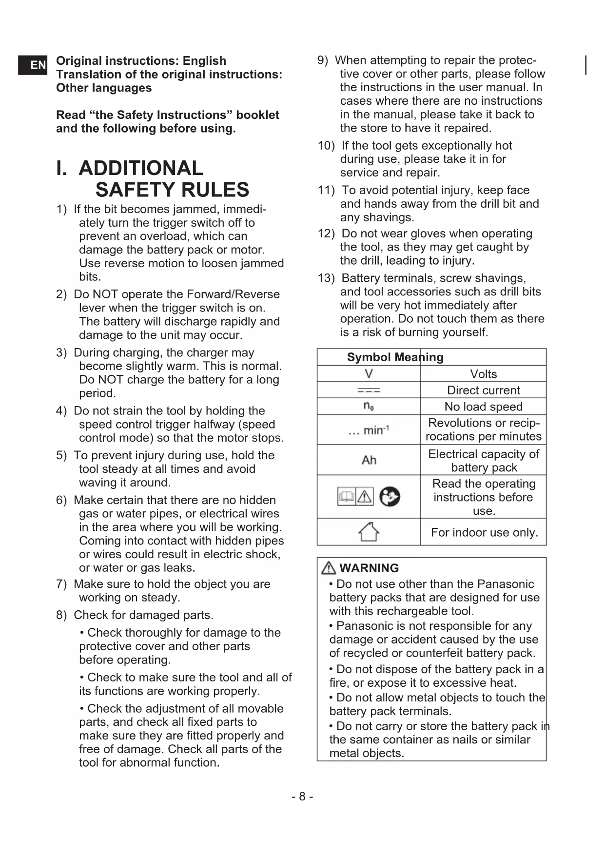
Impact Power Mode Select
The driver is preset to "Hard" impact mode setting when shipped from the manufacturer.
- Selecting the impact power among 5 modes (Hard, Self-drilling screw, Soft, Medium, Dash).
Press the impact power mode button to set it. The mode changes to Hard, Self-drilling screw, Soft, Medium or Dash each time the button is pressed.
* i.p.m. = Impact per minute.
Hard

0-2800 rpm and
0-3100 i.p.m.
- Jobs requiring high torque.
Medium

0-1450 rpm and
0-2500 i.p.m.
- Jobs requiring decent torque.
Soft
0-950 rpm and
0-1800 i.p.m.
- Jobs requiring limited torque.
- Jobs requiring minimal damage of finished exterior surface.
Self-drilling screw
0 - 2500 rpm and
0-2800 i.p.m.
Jobs requiring flush finish of self-drilling screw.
4mm× (15mm or smaller)
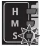
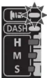
Dash
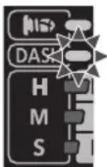
2800 rpm and
3100 i.p.m.
- If you want to always work at full speed and full power regardless of the trigger switch pull-in amount.
Avoid repeatedly depressing the switch when the bolts and screws are securely fastened.
Not doing so may cause a delay in rotation starting, or the Impact Power mode display to flash and prevent rotation from starting for circuit protection.
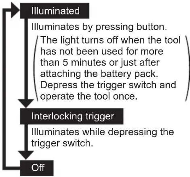
LED Light
Press the light button and set illumination condition.
CAUTION:
Do not use it as a substitute for a regular flashlight, since it does not have enough brightness.
CAUTION:DO NOT STARE INTO BEAM.
Use of controls or adjustments or performance of procedures other than those specified herein may result in hazardous radiation exposure.
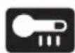
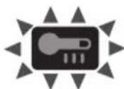
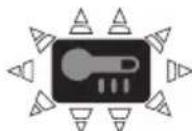
Overheat warning

Indicates operation has been halted due to motor or battery overheating.
- If the overheating protection feature activates, allow the tool to cool thoroughly (at least 30 minutes). The tool is ready for use when the overheat warning lamp goes out.
- Avoid using the tool in a way that causes the overheating protection feature to activate repeatedly.
The performance of the EY9L42 deteriorates significantly at and below 10^ due to work conditions and other factors.
Battery Level Indicator
Press the battery level button. It shifts to Impact power mode when release the button.
NOTE:
The indicator will not show the battery level even the button is pressed in the following cases.
The main unit is powered off.
- Just after attaching the battery pack
- The main unit or battery level button is not operated for approx. five minutes. Press the battery level button again after depressing the trigger switch.
| Indicator Battery status | ||
| 3 lamps illuminated | Charged enough | |
| 2 lamps illuminated | Approx. 60% remaining | |
| One lamp illuminated | Battery level is low. | |
| 3 lamps flashing | Empty | |
[Battery Pack]
For Appropriate Use of Battery Pack [Fig.7]
- For optimum battery life, store the Li-ion battery pack following use without charging it.
- When operating the battery pack, make sure the work place is well ventilated.
For safe use
- If the battery pack is not connected firmly when the switch is switched on, the overheat warning lamp and the battery low warning lamp will flash to indicate that safe operation is not possible, and the main unit will not rotate normally. Connect the battery pack into the unit of the tool until the red or yellow label disappears.
- Only use rechargeable battery packs for Panasonic rechargeable tools. Do not use modified battery packs (including battery packs which have been disassembled and parts replaced).
- Do not use deteriorated battery packs. There is a risk of the generation of heat, ignition and explosion.
- If a battery pack leaks fluid, cease use, keep away from open flames, and return it to the store immediately.
- Attach the battery pack by sliding until the yellow and red labels are no longer visible, and check that it does not fall out of place.
- Failure to do so may result in scalding.
- The usage temperature range for lithium ion battery packs is 0 to 40 degrees.
- Use of battery packs cooled to below zero, such as in colder northern areas, may result in abnormal operation of the device. In such cases, leave the battery pack in a location of 10 degrees or more for one hour or more before use, and only use the device after the battery pack has warmed up.
[Battery Charger]
Charging CAUTION:
1) If the temperature of the battery pack falls approximately below -10^ (14^) , charging will automatically stop to prevent degradation of the battery.
2) The ambient temperature range is between 0^ (32^) and 40^ (104^) . If the battery pack is used when the battery temperature is below 0^ (32^) , the tool may fail to function properly.
3) Use the charger at temperatures between 0^ and 40^ , and charge the battery at a temperature similar to that of the battery itself. (There should be no more than a 15^ difference between the temperatures of the battery and the charging location.)
4) When charging a cool battery pack (below 0^ (32^) ) in a warm place, leave the battery pack at the place and wait for more than one hour to warm up the battery to the level of the ambient temperature.
5) Cool down the charger when charging more than two battery packs consecutively.
6) Do not insert your fingers into contact hole, when holding charger or any other occasions.
7) To prevent the risk of fire or damage to the battery charger.
- Do not cover vent holes on the charger and the battery pack.
- Unplug the charger when not in use.
8) Store the charger between 0 and 40 degrees, and charge the battery pack at a temperature close to the storage temperature.
- If the battery pack is charged while at a temperature below 0 degrees, a full charge will give only around 50% of a normal charge. Commence charging after 1 hour or more at the prescribed temperature.
9) Do not charge in a poorly ventilated place.
NOTE:
Your battery pack is not fully charged at the time of purchase. Be sure to charge the battery before use.
How to charge
- Plug the charger into the AC outlet.
NOTE:
Sparks may be produced when the plug is inserted into the AC power supply, but this is not a problem in terms of safety.
- Connect the battery pack firmly into the charger.
1 Line up the alignment marks and place the battery onto the dock on the charger.
NOTE:
Not all battery packs display the alignment mark (Q) (on page 2).
2 Slide forward in the direction of the arrow. [Fig.8]
-
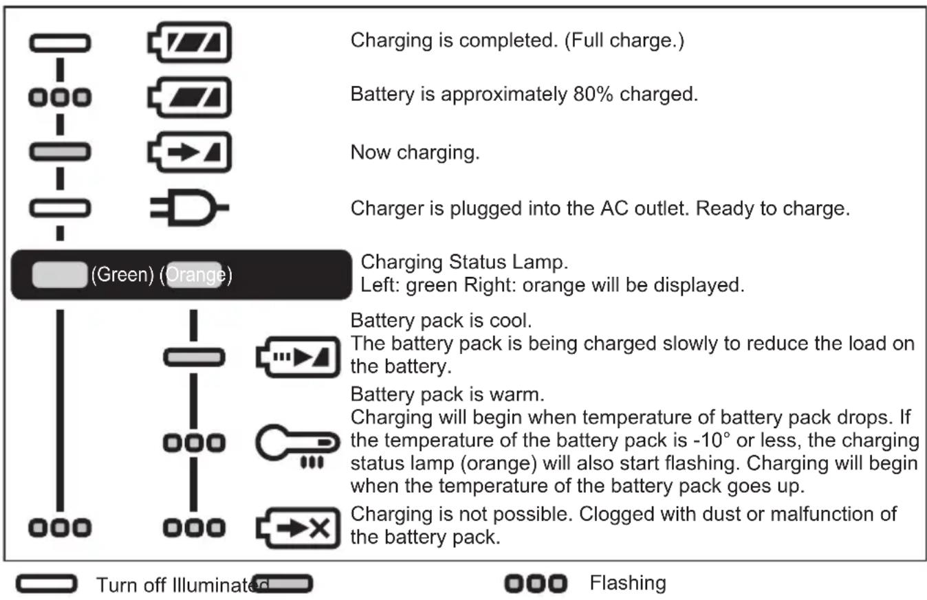
During charging, the charging lamp will be lit. When charging is completed, an internal electronic switch will automatically be triggered to prevent overcharging.
-
Charging will not start if the battery pack is hot (for example, immediately after heavy-duty operation).
The orange standby lamp will be flashing until the battery cools down.
Charging will then begin automatically.
- The charge lamp (green) will flash slowly once the battery is approximately 80% charged.
- When charging is completed, the charging lamp in green color will turn off.
- If the temperature of the battery pack is 0^ or less, charging takes longer to fully charge the battery pack than the standard charging time.
Even when the battery is fully charged, it will have approximately 50% of the power of a fully charged battery at normal operating temperature.
- Consult an authorized dealer if the charging lamp (green) does not turn off.
- If a fully charged battery pack is inserted into the charger again, the charging lamp lights up. After several minutes, the charging lamp in green color will turn off.
- Remove the battery pack while the battery pack release button is held up. [Fig.8]
LAMP INDICATIONS
ATTENTION:
For environmental protection and recycling of materials, be sure that it is disposed of at an officially assigned location, if there is one in your country.
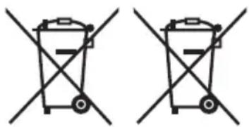
These symbols indicate separate collection of waste electrical and electronic equipment or waste batteries.
More detailed information is contained in the full version Operating Instructions.
https://www.panasonic-powertools.eu/en/construction/documents.htm
IV. MAINTENANCE
- Use only a dry, soft cloth for wiping the unit.
Do not use a damp cloth, thinner, benzine, or other volatile solvents for cleaning. - In the event that the inside of the tool or battery pack is exposed to water, drain and allow to dry as soon as possible. Carefully remove any dust or iron filings that collect inside the tool. If you experience any problems operating the tool, consult with a repair shop.
V. OPTIONAL ACCESSORIES
- Use only suitable size of bit.
VI. APPENDIX
MAXIMUM RECOMMENDED CAPACITIES
| Model No. EY76A1 | ||
| Screw driving | Wood screw Φ 3.5 | mm - Φ 9.5 mm |
| Self-drilling screw Φ 3.5 mm - Φ 6 mm | ||
| Bolt fastening | Standard bolt M6 - | M16 |
| High tensile bolt M6 - M12 | ||
WARRANTY SUPPLEMENT
The breakdown and damage caused by usage consistent for a long time (e.g.: factory work on the assembly line, etc.) is out of warranty.
VII. SPECIFICATIONS
NOTE: Weight indication
Greater than or equal to 1kg : indicated by 0.05kg
Less than 1 kg: indicated by 0.01kg
EN
MAIN UNIT
| Model No. EY76A1 | |||
| Motor voltage 14.4 V DC 18 V DC | |||
| No load speed [min-1 (rpm)] | Soft mode | 0 - 950 | |
| Medium mode | 0 - 1450 | ||
| Hard mode | 0 - 2800 | ||
| Self-drilling screw mode | 0 - 2800 | ||
| Dash mode | 2800 | ||
| Maximum torque | 160 N·m 170 N·m | ||
| Impact per minute [min-1 (i.p.m.)] | Soft mode | 0 - 1800 | |
| Medium mode | 0 - 2500 | ||
| Hard mode | 0 - 3100 | ||
| Self-drilling screw mode | 0 - 1800 | ||
| Dash mode | 3100 | ||
| Overall length 127 mm | |||
| Weight With battery pack: | EY9L45 | 1.55 kg— | |
| EY9L47 | 1.35 kg— | ||
| EY9L50 | — 1.65 kg | ||
| EY9L51 | — 1.70 kg | ||
| EY9L52 | — 1.45 kg | ||
| EY9L53 | — 1.45 kg | ||
| EY9L54 | — 1.70 kg | ||
| Noise, Vibration See the included sheet | |||
VIII. CAUTION FOR AC MAINS LEAD
FOR YOUR SAFETY PLEASE READ THE FOLLOWING TEXT CAREFULLY
This appliance is supplied with a moulded three pin mains plug for your safety and convenience. A 5 amp fuse is fitted in this plug.
Should the fuse need to be replaced please ensure that the replacement fuse has a rating of 5 amp and that it is approved by ASTA or BSI to BS1362.
Check for the ASTA mark or the BSI mark on the body of the fuse.
If the plug contains a removable fuse cover you must ensure that it is refitted when the fuse is replaced.
If you lose the fuse cover the plug must not be used until a replacement cover is obtained.
A replacement fuse cover can be purchased from your local Panasonic Dealer.
CAUTION:
IF THE FITTED MOULDED PLUG IS UNSUITABLE FOR THE SOCKET OUTLET IN YOUR HOME THEN THE FUSE SHOULD BE REMOVED AND THE PLUG CUT OFF AND DISPOSED OF SAFELY. THERE IS A DANGER OF SEVERE ELECTRICAL SHOCK IF THE CUT OFF PLUG IS INSERTED INTO ANY 13 AMP SOCKET.
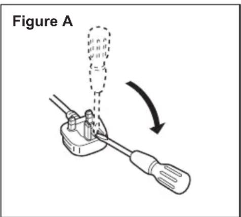
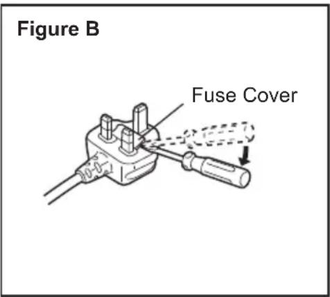
How to replace the fuse
The location of the fuse differs according to the type of AC mains plug (figures A and B).
Confirm the AC mains plug fitted and follow the instructions below. Illustrations may differ from actual AC mains plug. Open the fuse cover with a screwdriver and replace the fuse and close or attach the fuse cover.
Clignotant: Surchauffe (battery)
V. ACCESSORIES OPTIONNELS
https://www.panasonic-powertools.eu/en/construction/documents.htm
IV. MANUTENZIONE
- Bewaar reserve-bits.
V. OPTIONE ACCESSOIRES
https://www.panasonic-powertools.eu/en/construction/documents.htm
IV. VEDLIGEHOLDELS
Varning for overhetting

Slackt (normal drift)
Lyser: Overhettning (motor)
Blinkande: Overhett- ning (battery)
https://www.panasonic-powertools.eu/en/construction/documents.htm
IV. VEDLIKEHOLD
Importer for Turkey:
Panasonic Life Solutions Elektrik Sanayi ve Ticaret Anonim Şirketi
Abdurrahmangazi Mah. Ebubekir Cad. No: 44
34887 Sancaktepe Istanbul/Turkiye
For full version Operating Instructions, please refer to the web site. https://www.panasonic-powertools.eu/en/construction/documents.htm
Panasonic Testing Centre
Panasonic Marketing Europe GmbH
Winsberging 15, 22525 Hamburg, Germany
Panasonic Corporation 1006,Kadoma,Osaka 571-8501,Japan http://www.panasonic.com

- Original instructions: English Translation of the original instructions: Other languages
- ADDITIONAL SAFETY RULES
- WARNING
- ASSEMBLY
- NOTE:
- Attaching or Removing Bit
- Attaching or Removing Battery Pack
- OPERATION
- WARNING!
- [Main Body]
- CAUTION
- Switch and Forward/Reverse Lever Operation [Fig.3]
- CAUTION:
- Changing the Belt Hook Location Side [Fig.4]
- How to use spare bit storage
- Impact Power Mode Select
- Hard
- Medium
- Soft
- Self-drilling screw
- Dash
- LED Light
- CAUTION:DO NOT STARE INTO BEAM.
- Overheat warning
- Battery Level Indicator
- [Battery Pack]
- For Appropriate Use of Battery Pack [Fig.7]
- For safe use
- [Battery Charger]
- Charging CAUTION:
- How to charge
- LAMP INDICATIONS
- ATTENTION:
- MAINTENANCE
- OPTIONAL ACCESSORIES
- APPENDIX
- WARRANTY SUPPLEMENT
- SPECIFICATIONS
- CAUTION FOR AC MAINS LEAD
- FOR YOUR SAFETY PLEASE READ THE FOLLOWING TEXT CAREFULLY
- How to replace the fuse
- ACCESSORIES OPTIONNELS
- MANUTENZIONE
- OPTIONE ACCESSOIRES
- VEDLIGEHOLDELS
- Varning for overhetting
- VEDLIKEHOLD
Brand : PANASONIC
Model : EY76A1
Category : Drill