
AdvancedGrind 18 - Battery BOSCH - Free user manual and instructions
Find the device manual for free AdvancedGrind 18 BOSCH in PDF.
| Brand | Bosch |
| Model | AdvancedGrind 18 |
| Product Type | Cordless Angle Grinder |
| Power Supply | 18 V lithium-ion battery (recommended PBA 18V...W-) |
| Recommended Charger | AL 18... |
| Rated Voltage | 18 V |
| Rated Speed (no load) | 11,500 rpm |
| Speed Adjustment Range | 2,800 – 11,500 rpm |
| Max Disc Diameter | 125 mm |
| Spindle Thread | M14 |
| Max Thread Length | 21.7 mm |
| Weight (with 2.5 Ah battery and standard handle) | 2.4 kg |
| Weight (with 6.0 Ah battery and anti-vibration handle) | 3.2 kg |
| Main Functions | Grinding, sanding, wire brushing, cutting |
| Electronic Constant | Yes (speed holding under load) |
| Speed Preselection | Yes (wheel 2-6) |
| Soft Start | Yes |
| Restart Protection | Yes |
| Overload Protection | Yes |
| Battery Charge Indicator | 3 green LEDs (11-100%) |
| Recommended Charging Temperature | 0 °C to +35 °C |
| Operating and Storage Temperature | -20 °C to +50 °C |
| Sound Pressure Level (LpA) | 86 dB(A); uncertainty K=3 dB |
| Sound Power Level (LwA) | 97 dB(A); uncertainty K=3 dB |
| Vibrations (grinding) | 10.0 m/s²; K=1.5 m/s² |
| Vibrations (sanding) | 4.0 m/s²; K=1.5 m/s² |
| Maintenance | Regularly clean ventilation slots; store accessories carefully |
| Spare Parts and Repairability | Exploded views and parts at www.bosch-pt.com; Bosch after-sales service |
Frequently Asked Questions - AdvancedGrind 18 BOSCH
User questions about AdvancedGrind 18 BOSCH
0 question about this device. Answer the ones you know or ask your own.
Ask a new question about this device
Download the instructions for your Battery in PDF format for free! Find your manual AdvancedGrind 18 - BOSCH and take your electronic device back in hand. On this page are published all the documents necessary for the use of your device. AdvancedGrind 18 by BOSCH.
USER MANUAL AdvancedGrind 18 BOSCH
ruCpHnHaHbHOpyKOBQCTBO NO
OKnnnyataaHH
ukOpHHeHCHDyuaa3
ekcnyataui
kknainanayHxKAYaHbH
TyHcyckacb
ro Instrukturi originale
bgOpHnHaHnCTpyKun
mkOprrnHaHNo ynaTcBo 3a pa6ora
sr Originalno upstvo za rad
sl Izvira na vovdila
hr Originaline upute za rad
et Alguparane kasutusuhend
Instrukcijas originalaValoda
It Original instrukcija
ar Llo81 Jgaiuui

Deutsch .Seite 6
English Page 16
Francais.. Page 25
Espanol . Pagina 36
Portugues . Pagina 46
Italiano . 57
Nederlands.. 67
Dansk. Side 78
Svensk. Sidan 87
Norsk. Side 96
Suomi .Sivu 105
EAAynika. 2eAia 114
Türkce Sayfa 125
Polski Strona 136
Čestina. Stranka 147
Slovencina Stranka 156
Magyar .Oldal 166
Pycckn. CtpaHua 176
YkpaHcbka ..CtoipHa 189
Kazak. 5er 201
Romana.. .Pagina 213
www.bosch-pt.com/serviceaddresses
Transport
General Power Tool SafetyWarnings
WARNING
Read all safety warnings and all instructions. Failure to follow the
warnings and instructions may result in electric shock, fire and/or serious injury.
Save all warnings and instructions for future reference.
The term "power tool" in the warnings refers to your mains-operated (corded) power tool or battery-operated (cordless) power tool.
Work area safety
- Keep work area clean and well lit. Cluttered or dark areas invite accidents.
Do not operate power tools in explosive atmospheres, such as in the presence of flammable liquids, gases or dust. Power tools create sparks which may ignite the dust or fumes. - Keep children and bystanders away while operating a power tool. Distractions can cause you to lose control.
Electrical safety
Power tool plugs must match the outlet. Never modify the plug in any way. Do not use any adapter plugs with earthed (grounded) power tools. Unmodified plugs and matching outlets will reduce risk of electric shock.
- Avoid body contact with earthed or grounded surfaces, such as pipes, radiators, ranges and refrigerators. There is an increased risk of electric shock if your body is earthed or grounded.
Do not expose power tools to rain or wet conditions. Water entering a power tool will increase the risk of electric shock.
Do not abuse the cord. Never use the cord for carrying, pulling or unplugging the power tool. Keep cord away from heat, oil, sharp edges or moving parts. Damaged or entangled cords increase the risk of electric shock.
- When operating a power tool outdoors, use an extension cord suitable for outdoor use. Use of a cord suitable for outdoor use reduces the risk of electric shock..
If operating a power tool in a damp location is unavoidable, use a residual current device (RCD) protected supply. Use of an RCD reduces the risk of electric shock.
Personal safety
Stay alert, watch what you are doing and use common sense when operating a power tool. Do not use a power tool while you are tired or under the influence of drugs, alcohol or medication. A moment of inattention while operating power tools may result in serious personal injury.
Use personal protective equipment. Always wear eye protection. Protective equipment such as dust mask, non-skid safety shoes, hard hat, or hearing protection used for appropriate conditions will reduce personal injuries.
Prevent unintentional starting. Ensure the switch is in the off-position before connecting to power source and/or battery pack, picking up or carrying the tool. Carrying power tools with your finger on the switch or energising power tools that have the switch on invites accidents.
Remove any adjusting key or wrench before turning the power tool on. A wrench or a key left attached to a rotating part of the power tool may result in personal injury.
Do not overreach. Keep proper footing and balance at all times. This enables better control of the power tool in unexpected situations.
Dress properly. Do not wear loose clothing or jewellery. Keep your hair, clothing and gloves away from moving parts. Loose clothes, jewellery or long hair can be caught in moving parts.
If devices are provided for the connection of dust extraction and collection facilities, ensure these are con
nected and properly used. Use of dust collection can reduce dust-related hazards.
Power tool use and care
Do not force the power tool. Use the correct power tool for your application. The correct power tool will do the job better and safer at the rate for which it was designed.
Do not use the power tool if the switch does not turn it on and off. Any power tool that cannot be controlled with the switch is dangerous and must be repaired.
- Disconnect the plug from the power source and/or the battery pack from the power tool before making any adjustments, changing accessories, or storing power tools. Such preventive safety measures reduce the risk of starting the power tool accidentally.
- Store idle power tools out of the reach of children and do not allow persons unfamiliar with the power tool or these instructions to operate the power tool. Power tools are dangerous in the hands of untrained users.
- Maintain power tools. Check for misalignment or binding of moving parts, breakage of parts and any other condition that may affect the power tool's operation. If damaged, have the power tool repaired before use. Many accidents are caused by poorly maintained power tools.
- Keep cutting tools sharp and clean. Properly maintained cutting tools with sharp cutting edges are less likely to bind and are easier to control.
- Use the power tool, accessories and tool bits etc. in accordance with these instructions, taking into account the working conditions and the work to be performed. Use of the power tool for operations different from those intended could result in a hazardous situation.
Battery tool use and care
- Recharge only with the charger specified by the manufacturer. A charger that is suitable for one type of battery pack may create a risk of fire when used with another battery pack.
- Use power tools only with specifically designated battery packs. Use of any other battery packs may create a risk of injury and fire.
- When battery pack is not in use, keep it away from other metal objects, like paper clips, coins, keys, nails, screws or other small metal objects, that can make a connection from one terminal to another. Shorting the battery terminals together may cause burns or a fire.
Under abusive conditions, liquid may be ejected from the battery; avoid contact. If contact accidentally occurs, flush with water. If liquid contacts eyes, additionally seek medical help. Liquid ejected from the battery may cause irritation or burns.
Service
Have your power tool serviced by a qualified repair person using only identical replacement parts. This will ensure that the safety of the power tool is maintained.
SafetyWarnings for AngleGrinder
SafetyWarnings common for Grinding, Sanding,Wire Brushing or Abrasive Cutting Off operations
This power tool is intended to function as a grinder, sander, wire brush or cut-off tool. Read all safety warnings, instructions, illustrations and specifications provided with this power tool. Failure to follow all instructions listed below may result in electric shock, fire and/or serious injury.
Operations such as polishing are not recommended to be performed with this power tool. Operations for which the power tool was not designed may create a hazard and cause personal injury.
- Do not use accessories which are not specifically designed and recommended by the tool manufacturer. Just because the accessory can be attached to your power tool, it does not assure safe operation.
The rated speed of the accessory must be at least equal to the maximum speed marked on the power tool. Accessories running faster than their rated speed can break and fly apart.
The outside diameter and the thickness of your accessory must be within the capacity rating of your power tool. Incorrectly sized accessories cannot be adequately guarded or controlled.
- Threaded mounting of accessories must match the grinder spindle thread. For accessories mounted by flanges, the arbour hole of the accessory must fit the locating diameter of the flange. Accessories that do not match the mounting hardware of the power tool will run out of balance, vibrate excessively and may cause loss of control.
Do not use a damaged accessory. Before each use inspect the accessory such as abrasive wheels for chips and cracks, backing pad for cracks, tear or excess wear, wire brush for loose or cracked wires. If power tool or accessory is dropped, inspect for damage or install an undamaged accessory. After inspecting and installing an accessory, position yourself and bystanders away from the plane of the rotating accessory and run the power tool at maximum no load speed for one minute. Damaged accessories will normally break apart during this test time.
Wear personal protective equipment. Depending on application, use face shield, safety goggles or safety glasses. As appropriate, wear dust mask, hearing protectors, gloves and workshop apron capable of stopping small abrasive or workpiece fragments. The eye protection must be capable of stopping flying debris generated by various operations. The dust mask or respirator must be capable of filtrating particles generated by
your operation. Prolonged exposure to high intensity noise may cause hearing loss.
- Keep bystanders a safe distance away from work area. Anyone entering the work area must wear personal protective equipment. Fragments of workpiece or of a broken accessory may fly away and cause injury beyond immediate area of operation.
Hold the power tool by insulated gripping surfaces only, when performing an operation where the cutting accessory may contact hidden wiring. Contact with a "live" wire will also make exposed metal parts of the power tool "live" and could give the operator an electric shock. - Never lay the power tool down until the accessory has come to a complete stop. The spinning accessory may grab the surface and pull the power tool out of your control.
Do not run the power tool while carrying it at your side. Accidental contact with the spinning accessory could snag your clothing, pulling the accessory into your body.
Regularly clean the power tool's air vents. The motor's fan will draw the dust inside the housing and excessive accumulation of powdered metal may cause electrical hazards.
Do not operate the power tool near flammable materials. Sparks could ignite these materials.
Do not use accessories that require liquid coolants. Using water or other liquid coolants may result in electrocution or shock.
Kickback and RelatedWarnings
Kickback is a sudden reaction to a pinched or snagged rotating wheel, backing pad, brush or any other accessory. Pinching or snagging causes rapid stalling of the rotating accessory which in turn causes the uncontrolled power tool to be forced in the direction opposite of the accessory's rotation at the point of the binding.
For example, if an abrasive wheel is snagged or pinched by the workpiece, the edge of the wheel that is entering into the pinch point can dig into the surface of the material causing the wheel to climb out or kick out. The wheel may either jump toward or away from the operator, depending on direction of the wheel's movement at the point of pinching. Abrasive wheels may also break under these conditions. Kickback is the result of power tool misuse and/or incorrect operating procedures or conditions and can be avoided by taking proper precautions as given below.
- Maintain a firm grip on the power tool and position your body and arm to allow you to resist kickback forces. Always use auxiliary handle, if provided, for maximum control over kickback or torque reaction during start-up. The operator can control torque reactions or kickback forces, if proper precautions are taken.
Never place your hand near the rotating accessory. Accessory may kickback over your hand.
Do not position your body in the area where power tool will move if kickback occurs. Kickback will propel the tool in direction opposite to the wheel's movement at the point of snagging.
Use special care when working corners, sharp edges etc. Avoid bouncing and snagging the accessory.
Corners, sharp edges or bouncing have a tendency to snag the rotating accessory and cause loss of control or kickback.
Do not attach a saw chain woodcarving blade or toothed saw blade. Such blades create frequent kickback and loss of control.
SafetyWarnings specific for Grinding and Abrasive Cutting-Off operations
Use only wheel types that are recommended for your power tool and the specific guard designed for the selected wheel. Wheels for which the power tool was not designed cannot be adequately guarded and are unsafe.
The grinding surface of centre depressed wheels must be mounted below the plane of the guard lip. An improperly mounted wheel that projects through the plane of the guard lip cannot be adequately protected.
The guard must be securely attached to the power tool and positioned for maximum safety, so the least amount of wheel is exposed towards the operator. The guard helps to protect operator from broken wheel fragments, accidental contact with wheel and sparks that could ignite clothing.
- Wheels must be used only for recommended applications. For example: do not grind with the side of cutoff wheel. Abrasive cut-off wheels are intended for peripheral grinding, side forces applied to these wheels may cause them to shatter.
Always use undamaged wheel flanges that are of correct size and shape for your selected wheel. Proper wheel flanges support the wheel thus reducing the possibility of wheel breakage. Flanges for cut-off wheels may be different from grinding wheel flanges.
Do not use worn down wheels from larger power tools. Wheel intended for larger power tool is not suitable for the higher speed of a smaller tool and may burst.
Additional SafetyWarnings specific for Abrasive Cutting Off operations
Do not "jam" the cut-off wheel or apply excessive pressure. Do not attempt to make an excessive depth of cut. Overstressing the wheel increases the loading and susceptibility to twisting or binding of the wheel in the cut and the possibility of kickback or wheel breakage.
Do not position your body in line with and behind the rotating wheel. When the wheel, at the point of operation, is moving away from your body, the possible kickback may propel the spinning wheel and the power tool directly at you.
- When wheel is binding or when interrupting a cut for any reason, switch off the power tool and hold the power tool motionless until the wheel comes to a com
plete stop. Never attempt to remove the cut-off wheel from the cut while the wheel is in motion otherwise kickback may occur. Investigate and take corrective action to eliminate the cause of wheel binding.
- Do not restart the cutting operation in the workpiece. Let the wheel reach full speed and carefully re-enter the cut. The wheel may bind, walk up or kickback if the power tool is restarted in the workpiece.
Support panels or any oversized workpiece to minimize the risk of wheel pinching and kickback. Large workpieces tend to sag under their own weight. Supports must be placed under the workpiece near the line of cut and near the edge of the workpiece on both sides of the wheel.
Use extra caution when making a "pocket cut" into existing walls or other blind areas. The protruding wheel may cut gas or water pipes, electrical wiring or objects that can cause kickback.
SafetyWarnings specific for Sanding operations
Do not use excessively oversized sanding disc paper. Follow manufacturers recommendations, when selecting sanding paper. Larger sanding paper extending beyond the sanding pad presents a laceration hazard and may cause snagging, tearing of the disc, or kickback.
SafetyWarnings specific for Wire Brushing operations
- Be aware that wire bristles are thrown by the brush even during ordinary operation. Do not overstress the wires by applying excessive load to the brush The wire bristles can easily penetrate light clothing and/or skin.
If the use of a guard is recommended for wire brushing, do not allow any interference of the wire wheel or brush with the guard. Wire wheel or brush may expand in diameter due to work load and centrifugal forces.
Additional safety information

Wear safety goggles.
Use suitable detectors to determine if there are hidden supply lines or contact the local utility company for assistance. Contact with electric cables can cause fire and electric shock. Damaging gas lines can lead to explosion. Breaking water pipes causes property damage.
Do not touch grinding and cutting discs until they have cooled down. The discs can become very hot while working.
Release the On/Off switch and set it to the Off position when the power supply is interrupted, e.g. when the battery pack is removed. This prevents uncontrolled restarting.
- Secure the workpiece. A workpiece clamped with clamping devices or in a vice is held more secure than by hand.
In case of damage and improper use of the battery, vapours may be emitted. The battery can set alight or ex
plode. Ensure the area is well ventilated and seek medical attention should you experience any adverse effects. The vapours may irritate the respiratory system.
Do not open the battery. There is a risk of short-circuiting.
The battery can be damaged by pointed objects such as nails or screwdrivers or by force applied externally. An internal short circuit may occur, causing the battery to burn, smoke, explode or overheat.
Only use the battery with products from the manufacturer. This is the only way in which you can protect the battery against dangerous overload.


Protect the battery against heat, e.g. against continuous intense sunlight, fire, dirt, water and moisture. There is a risk of explosion and short-circuiting.
Product Description and Specifications

Read all the safety and general instructions. Failure to observe the safety and general instructions may result in electric shock, fire and/or serious injury.
Please observe the illustrations at the beginning of this operating manual.
Intended use
The power tool is intended for cutting, grinding, roughing and brushing metal materials without the use of water.
A separate protective guard for cutting must be used when cutting with bonded abrasives.
Sufficient dust extraction must be provided when cutting stone.
With approved abrasive tools, the power tool can be used for sanding with sanding discs.
Product Features
The numbering of the product features refers to the diagram of the power tool on the graphics page.
(1) Unlocking lever for protective guard
(2) Spindle lock button
(3) Direction of rotation arrow on housing
(4) On/off switch
(5) Battery charge indicator
(6) Battery
(7) Speed preselection thumbwheel
(8) Battery release buttona)
(9) Auxiliary handle (insulated gripping surface)
(10) Protective guard for grinding
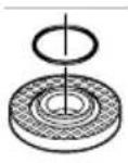
(11) Mounting flange with O-ring
(12) Grinding disc
(13) Protective guard for cuttinga)
(14) Cutting disca)
(15) Carbide grinding head
(16) Quick-clamping nut with bar
(17) Grinding spindle
(18) Hand guarda)
(19) Rubber sanding pad
(20) Abrasive disca)
(21) Round nuta)
(22) Cup brusha)
(23) Handle (insulated gripping surface)
(24) Extraction guard for cutting with a cutting guide
(25) Diamond cutting disc a)
a) Accessories shown or described are not included with the product as standard. You can find the complete selection of accessories in our accessories range.
Technical Data
Angle grinder AdvancedGrind 18
| Article number | 3603 CD9 0.. | |
| Rated voltage V= 18 | ||
| Rated speedA) | min-1 | 11500 |
| Speed adjustment range min | -1 | 2800–11500 |
| Max. grinding disc diameter mm 125 | ||
| Grinding spindle thread M 14 | ||
| Max. thread length of grind-ing spindle | mm 21,7 | |
| Constant electronic control ● | ||
| Speed preselection ● | ||
| Soft start ● | ||
| Restart protection ● | ||
| Overload protection ● | ||
| Weight according to EPTA-Procedure 01:2014B) | ||
| - with low-vibration auxiliary handle | kg 2.7 (2.5 Ah)-3.2 (6.0 Ah) | |
| - with standard auxiliary handle | kg 2.4 (2.5 Ah)-3.0 (6.0 Ah) | |
| Recommended ambient temperature during charging | °C 0 to +35 | |
| Permitted ambient temperature during operationC) and during storage | °C | -20 to +50 |
| Recommended rechargeable batteries | PBA 18V...W-. | |
| Recommended chargersD) | AL 18... | |
A) Measured at 20 - 25^ with rechargeable battery PBA 18V 6.0Ah.
B) Depends on battery in use
C) Limited performance at temperatures < 0^
D) The following chargers are not compatible with the PBA rechargeable battery: AL 1814 CV, AL 1820 CV, AL 1860 CV
Noise/Vibration Information
Noise emission values determined according to
EN 60745-2-3.
Typically the A-weighted noise level of the power tool are: 86 dB(A); sound power level 97 dB(A). Uncertainty K = 3 dB.
Wear hearing protection!
Vibration total values a_n (triax vector sum) and uncertainty K determined according to EN 60745-2-3:
Surface grinding (roughing):
a_n = 10.0m / s^2 K = 1.5m / s^2
Disc sanding:
a_n = 4.0m / s^2 K = 1.5m / s^2
The vibration level given in these instructions has been measured in accordance with a standardised measuring procedure and may be used to compare power tools. It can also be used for a preliminary estimation of exposure to vibration.
The stated vibration level applies to the main applications of the power tool. However, if the power tool is used for different applications, with different application tools or poorly maintained, the vibration level may differ. This can significantly increase the exposure to vibration over the total working period.
To estimate the exposure to vibration accurately, the times when the tool is switched off or when it is running but not actually being used should also be taken into account. This can significantly reduce the exposure to vibration over the total working period.
Implement additional safety measures to protect the operator from the effects of vibration, such as servicing the power tool and application tools, keeping the hands warm, and organising workflows correctly.
Fitting
Charging the battery
- Use only the chargers listed in the technical data. Only these chargers are matched to the lithium-ion battery of your power tool.
Note: The battery is supplied partially charged. To ensure full battery capacity, fully charge the battery in the charger before using your power tool for the first time.
The lithium-ion battery can be charged at any time without reducing its service life. Interrupting the charging process does not damage the battery.
The lithium-ion battery is protected against deep discharge by the "Electronic Cell Protection (ECP)". When the battery is discharged, the power tool is switched off by means of a protective circuit: The application tool no longer rotates.
Do not continue to press the On/Off switch after the power tool has automatically switched off. The battery can be damaged.
Follow the instructions on correct disposal.
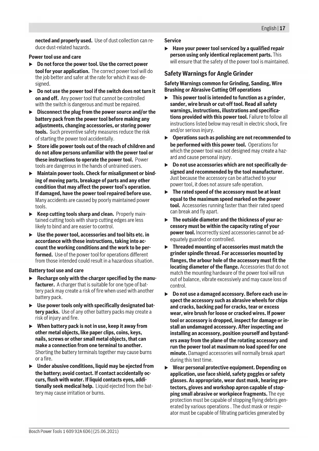
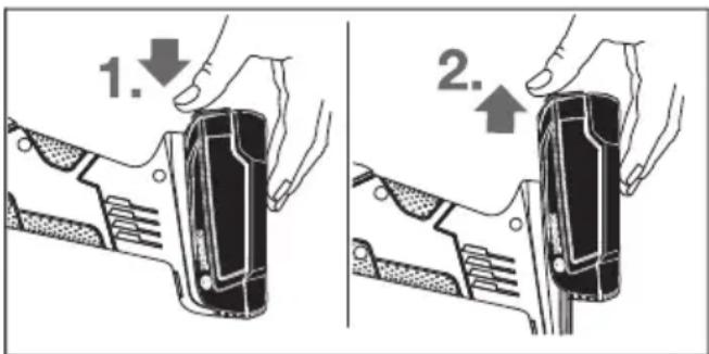
Removing the battery
To remove the battery (6), press the battery unlocking button (8) and pull the battery out of the power tool. Do not exert any force.
Charge-control Indicator
The charge-control indicator (5) displays the charge condition of the battery for several seconds when the On/Off switch (4) is half-pressed or fully pressed. It consists of 3 green LEDs.
LED Capacity
| Continuous lighting 3 x green ≥ 66% | |
| Continuous lighting 2 x green 33-66% | |
| Continuous lighting 1 x green 11-33% | |
| Slowly flashing light 1 x green ≤ 10% |
The 3 LEDs in the charge-control indicator flash quickly when the temperature of the battery is outside of the operating temperature range of -30 to +65^ and/or the overload protection has been triggered.
Fitting Protective Equipment
- Remove the battery from the power tool before carrying out work on the power tool (e.g. maintenance, changing tool, etc.). The battery should also be removed for transport and storage. There is risk of injury from unintentionally pressing the on/off switch.
Note: If the grinding disc breaks during operation or the holding fixtures on the protective guard/power tool become damaged, the power tool must be sent to the after-sales service immediately; see the "After-Sales Service and Application Service" section for addresses.
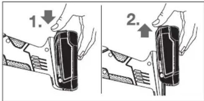
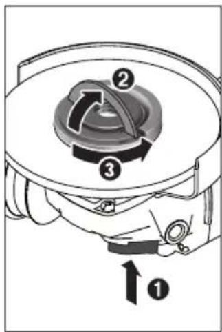
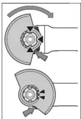
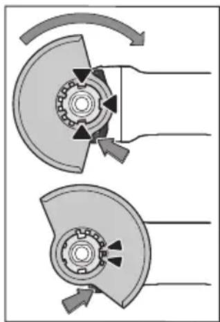
Protective guard for grinding
Place the protective guard (10) onto the holder on the power tool until the coding cams of the protective guard are aligned with the holder. When doing so, press and hold the unlocking lever (1). Press the protective guard (10) onto the spindle collar until the shoulder of the protective guard is sitting on the flange of the power tool and rotate the protective guard until it audibly clicks into
place.
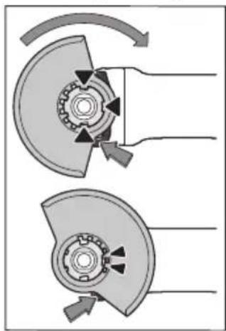
Adjust the position of the protective guard (10) to meet the requirements of the operation. To do this, push the unlocking lever (1) upward and rotate the protective guard (10) into the required position.
Always position the protective guard (10) such that the two cams on the unlocking lever (1) engage in the corresponding openings on the protective guard (10).
Adjust the protective guard (10) such that sparking in the direction of the operator is prevented.
The protective guard (10) must only be adjustable while the unlocking lever (1) is actuated. Otherwise, the power tool must not be used any more under any circumstances and must be sent to the after-sales service.
Note: The coding cams on the protective guard (10) ensure that only a protective guard that is suitable for the power tool can be fitted.
Protective guard for cutting
Always use the protective guard for cutting (13) when cutting with bonded abrasives.
Provide sufficient dust extraction when cutting stone.
The protective guard for cutting (13) is fitted in the same way as the protective guard for grinding (10).
Extraction guard for cutting with a guide block
The extraction guard for cutting with a guide block (24) is fitted in the same way as the protective guard for grinding (10).
Side handle
Do not operate your power tool without the side handle (9).
Screw the side handle (9) on the left or right of the machine head depending on how your are working.
Low-vibration auxiliary handle

Screw the auxiliary handle (9) on the left or right of the machine head depending on how your are working.
The low-vibration auxiliary handle reduces vibration, enabling the tool to be used safely and more comfortably.
Do not make any alterations of any kind to the auxiliary handle.
Do not continue to use a damaged auxiliary handle.
Hand guard
Always fit the hand guard (18) when working with the rubber sanding plate (19) or with the cup brush/disc brush/flap disc.
Attach the hand guard (18) to the side handle (9).
Fitting the Abrasive Tools
- Remove the battery from the power tool before carrying out work on the power tool (e.g. maintenance, changing tool, etc.). The battery should also be re
moved for transport and storage. There is risk of injury from unintentionally pressing the on/off switch.
Do not touch grinding and cutting discs until they have cooled down. The discs can become very hot while working.
Clean the grinding spindle (17) and all the parts to be fitted. Lock the grinding spindle with the spindle lock button (2) before clamping and releasing the abrasive tools.
Do not press the spindle lock button while the grinding spindle is moving. The power tool may become damaged if you do this.
Grinding/Cutting Disc
Pay attention to the dimensions of the abrasive tools. The diameter of the hole must match that of the mounting flange. Do not use an adapter or reducer.
When using diamond cutting discs, make sure that the direction of rotation arrow on the diamond cutting disc corresponds to the direction of rotation of the machine (see direction of rotation arrow on the housing).
See the graphics page for fitting instructions.
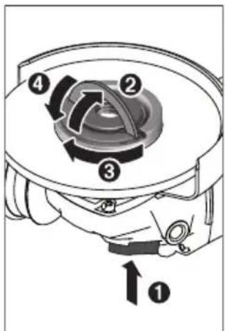
Use the quick-clamping nut (16) to secure the grinding/cutting disc without the need for additional tools.
The quick-clamping nut (16) may be used only for grinding or cutting discs.
Only use quick-clamping nuts (16) that are in good working order and not damaged.
When screwing on, make sure that the printed side of the quick-clamping nut (16) is not facing the grinding disc.
Always secure a grinding/cutting disc using only the quick-clamping nut (16) supplied.
Press the spindle lock button (2) to lock the grinding spindle. To tighten the quick-clamping nut (16), fold up the bar and turn the quick-clamping nut firmly clockwise. Then fold down the bar to secure the quick-clamping nut. It is not sufficient to tighten the disc along the edge.
Quick-clamping nuts (16) that are properly secured and not damaged can be removed by hand. To do this, fold up the bar and turn the quick-clamping nut firmly anticlockwise. If the quick-clamping nut is stuck, do not attempt to loosen it with a tool - always use a two-pin spanner.
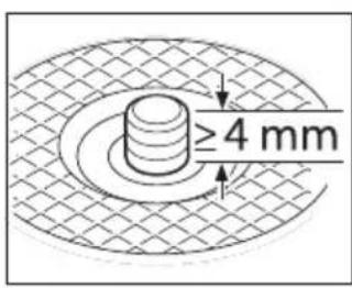
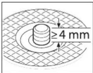
After fitting the hub flange and the grinding/cutting disc, the free thread length of the grinding spindle must be at least 4mm
Ensure that the abrasive tool is firmly seated, so that it does not twist away from
the spindle in the runout of the power tool.
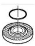
A plastic part (O-ring) is fitted around the cent-ring collar in the hub flange (11). If the O-ring is missing or damaged, the hub flange (11) must be replaced before operation can resume.
After fitting the abrasive tool, check that the abrasive tool is fitted correctly and can turn freely before switching on the power tool. Make sure that the abrasive tool does not brush against the protective guard or other parts.
Flap disc
Always fit the hand guard (18) when working with the flap disc.
Rubber Sanding Pad
Always fit the hand guard (18) when working with the rubber sanding pad (19).
See the graphics page for fitting instructions.
Slide the rubber sanding pad (19) onto the grinding spindle (17).
Press the sanding sheet (20) firmly onto the underside of the rubber sanding pad (19).
Screw on the round nut (21) and tighten with a two-pin spanner.
Cup brush/disc brush
Always fit the hand guard (18) when working with the cup brush or disc brush.
See the graphics page for fitting instructions.
The cup brush/disc brush must be screwed onto the grinding spindle until it rests firmly against the grinding spindle flange at the end of the grinding spindle thread. Tighten the cup brush/disc brush with an open-ended spanner.
Carbide Grinding Head
A grinding head may be used only with a suitable protective guard.
Approved abrasive tools
You can use all the abrasive tools mentioned in these operating instructions.
The permissible speed [^-1] or the circumferential speed [m / s] of the abrasive tools used must at least match the values given in the table.
It is therefore important to observe the permissible rotational/circumferential speed on the label of the abrasive tool.
| max. [mm] [mm] | ||||
| D bd [min] | -1] [m/s] | |||
| b d | 115 | 7 | 22.2 | 11,500 80 |
| 125 | 7 | 22.2 | 11,500 80 | |
| D | 115 | - | - | 11,500 80 |
| 125 | - | - | 11,500 80 | |
| b D | 75 30 M 14 11,500 45 | |||
Dust/Chip Extraction
Dust from materials such as lead-containing coatings, some wood types, minerals and metal can be harmful to one's health. Touching or breathing-in the dust can cause allergic reactions and/or lead to respiratory infections of the user or bystanders.
Certain dust, such as oak or beech dust, is considered carcinogenic, especially in connection with wood-treatment additives (chromate, wood preservative). Materials containing asbestos may only be worked by specialists.
-
Provide for good ventilation of the working place.
-
It is recommended to wear a P2 filter-class respirator.
Observe the relevant regulations in your country for the materials to be worked.
- Avoid dust accumulation at the workplace. Dust can easily ignite.
Operation
Starting Operation
Inserting the battery
Push the charged battery (6) into the base of the power tool until the battery is securely locked.
Switching on/off
To start the power tool, push the on/off switch (4) forward. To lock the on/off switch (4) in position, push the on/off switch (4) forward and down until it clicks into place.
To switch off the power tool, release the on/off switch (4); or, if the switch is locked, briefly push the on/off switch (4) backward and down and then release it.
Always check abrasive tools before using them. The abrasive tool must be fitted properly and be able to move freely. Carry out a test run for at least one minute with no load. Do not use abrasive tools that are damaged, run untrue or vibrate during use. Damaged abrasive tools can burst apart and cause injuries.
Restart protection
The restart protection feature prevents the power tool from uncontrolled starting after the power supply to it has been interrupted.
To restart the tool, set the on/off switch (4) to the off position and then switch the power tool on again.
Constant Electronic control
The Constant Electronic keeps the speed at no load and under load virtually consistent, guaranteeing uniform performance.
Soft start
The electronic soft start limits the torque when the power tool is switched on and increases the service life of the motor.
Speed preselection
You can select the required speed using the speed preselection thumbwheel (7), even during operation. The information in the table below describes the recommended values.
| Material Application Application tool Thumbwheel position | |||
| Metal Removing paint Sanding pad with sanding sheet 2-3 | |||
| Wood, metal | Brushing, removing rust | Cup brush, abrasive disc | 3 |
| Metal, stone Grinding | Grinding disc | 4-6 | |
| Metal Rough grinding | Grinding disc | 6 | |
| Metal Cutting | Cutting disc | 6 | |
| Stone | Cutting | Diamond cutting disc and cutting guide (cutting of stone is permitted only with a cutting guide) | |
The values specified for speed levels are guide values.
The rated speed of the accessory must be at least equal to the maximum speed marked on the power tool. Accessories running faster than their rated speed can break and fly apart.
Practical advice
Exercise caution when cutting slots in structural walls; see the "Information on structural design" section.
- Clamp the workpiece if it is not secure under its own weight.
Do not load the power tool so heavily that it comes to a stop.
If the power tool has been subjected to a heavy load, continue to run it at no-load for several minutes to cool down the accessory.
Do not use the power tool with a cut-off stand.
Do not touch grinding and cutting discs until they have cooled down. The discs can become very hot while working.
Rough grinding
Never use cutting discs for rough grinding.
The best rough grinding results are achieved with a set angle of 30^ to 40^ . Move the power tool back and forth with moderate pressure. This will ensure that the workpiece does not become too hot or discolour and that grooves are not formed.
Flap disc
The flap disc (accessory) enables you to machine curved surfaces and profiles.
Flap discs have a considerably longer service life, lower noise levels and lower sanding temperatures than conventional grinding discs.
Cutting metal
Always use the protective guard for cutting (13) when cutting with bonded abrasives.
When carrying out abrasive cutting, use a moderate feed that is suited to the material being machined. Do not exert pressure on the cutting disc and do not tilt or swing the power tool.
Do not attempt to reduce the speed of a cutting disc coming to a stop by applying pressure from the side.
The power tool must always work in an up-grinding motion. Otherwise there is a risk that it will be pushed uncontrolled out of the cut.
For best results when cutting profiles and rectangular tubing, start at the smallest cross section.
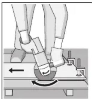
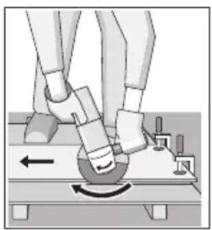
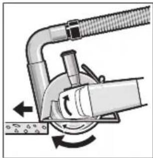
Cutting Stone (see figure A)
Provide sufficient dust extraction when cutting stone.
Wear a dust mask.
The power tool may be used only for dry cutting/grinding.
For best results when cutting stone, use a diamond cutting disc.
When using the extraction guard for cutting with a cutting guide (24), the vacuum cleaner must be approved for vacuuming stone dust. Suitable vacuum cleaners are available from Bosch.
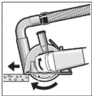
Switch on the power tool and position it with the front part of the cutting guide on the workpiece. Move the power tool with a moderate feed motion that is suited to the material being machined.
When cutting especially hard materials such as con
crete with a high pebble content, the diamond cutting disc can overheat and become damaged as a result. This is clearly indicated by circular sparking, rotating with the diamond cutting disc.
If this happens, stop cutting and allow the diamond cutting disc to cool down by running the power tool for a short time at maximum speed with no load.
If work is noticeably slower and with circular sparking, this indicates that the diamond cutting disc that has become dull. You can resharpen the disc by briefly cutting into abrasive material (e.g. lime-sand brick).
Information on structural design
Slots in load-bearing walls are subject to DIN 1053 part 1 or country-specific regulations. These regulations must be observed under all circumstances. Seek advice from the responsible structural engineer, architect or construction supervisor before starting work.
Recommendations for optimal handling of the battery
Protect the battery against moisture and water.
Only store the battery only within a temperature range of -20 to 50^ . Do not leave the battery in your car in the summer, for example.
Occasionally clean the ventilation slots on the battery using a soft brush that is clean and dry.
A significantly reduced operating time after charging indicates that the battery has deteriorated and must be replaced.
Follow the instructions on correct disposal.
Maintenance and Service
Maintenance and Cleaning
- Remove the battery from the power tool before carrying out work on the power tool (e.g. maintenance, changing tool, etc.). The battery should also be removed for transport and storage. There is risk of injury from unintentionally pressing the on/off switch.
To ensure safe and efficient operation, always keep the power tool and the ventilation slots clean.
Store and handle the accessories carefully.
After-Sales Service and Application Service
Our after-sales service responds to your questions concerning maintenance and repair of your product as well as spare parts. You can find explosion drawings and information on spare parts at: www.bosch-pt.com
The Bosch product use advice team will be happy to help you with any questions about our products and their accessories.
In all correspondence and spare parts orders, please always include the 10-digit article number given on the nameplate of the product.
Great Britain
Robert Bosch Ltd. (B.S.C.)
P.O.Box 98
Broadwater Park
North Orbital Road
Denham Uxbridge
UB95HJ
At www.bosch-pt.co.uk you can order spare parts or arrange the collection of a product in need of servicing or repair.
Tel. Service: (0344) 7360109
E-Mail: boschservicecentre@bosch.com
You can find further service addresses at:
www.bosch-pt.com/serviceaddresses
Transport
The contained lithium-ion batteries are subject to the Dangerous Goods Legislation requirements. The batteries are suitable for road-transport by the user without further restrictions.
When shipping by third parties (e.g.: by air transport or forwarding agency), special requirements on packaging and labelling must be observed. For preparation of the item being shipped, consulting an expert for hazardous material is required.
Dispatch battery packs only when the housing is undamaged. Tape or mask off open contacts and pack up the battery in such a manner that it cannot move around in the packaging. Please also observe the possibility of more detailed national regulations.
Disposal

Power tools, rechargeable batteries, accessories and packaging should be sorted for environmental-friendly recycling.
Do not dispose of power tools and batteries/re-chargeable batteries into household waste!
Only for EU countries:
According to the Directive 2012/19/EU, power tools that are no longer usable, and according to the Directive 2006/66/EC, defective or used battery packs/batteries,
must be collected separately and disposed of in an environmentally correct manner.
Only for United Kingdom
According to Waste Electrical and Electronic Equipment Regulations 2013 (2013/3113) and the Waste Batteries and Accumulators Regulations 2009 (2009/890), power tools that are no longer usable must be collected separately and disposed of in an environmentally friendly manner.
Battery packs/batteries:
Li-ion:
Please observe the notes in the section on transport (see "Transport", page 25).
Français
Protection anti-redemarrage
Robert Bosch (France) S.A.S.
www.bosch-pt.com/serviceaddresses
Transport
www.bosch-pt.com/serviceaddresses
Transporte
Montar as ferramentas de lixar
www.bosch-pt.com/serviceaddresses
Transporte
www.bosch-pt.com/serviceaddresses
Trasporto
www.bosch-pt.com/serviceaddresses
Vervoer
Bosch Service Center
Telegrafvej 3
2750 Ballerup
Pa www.bosch-pt.dk kan der online bestilles reservedele el-ler oprettes en reparations ordre.
Tlf. Service Center: 44898855
Fax: 44898755
E-Mail: vaerktoej@dk.bosch.com
www.bosch-pt.com/serviceaddresses
Transport
Bosch Service Center
Telegrafvej 3
2750 Ballerup
Danmark
Tel.: (08) 7501820 (inom Sverige)
Fax: (011) 187691
Du hittar fler kontaktuppgifter till service har:
www.bosch-pt.com/serviceaddresses
Transport
De litiumjonbatterier som ingar ar underkastade kraven for farligt gods. Anvandaren kan utan ytterligare forplichtelser transportera batterierna pa allman vag.
Overflatesliping (skrubbing):
a_n = 10,0m / s^2,K = 1,5m / s^2
Sliping med slipeskive:
a_n = 4,0m / s^2,K = 1,5m / s^2
Vernedeksel for sliping
Legg vernaldekselet (10) pa festet pa elektroverktoyet. Kodetappene pa vernaldekselet skal stemme overens med festet. Mens du gjrdete,trykker du pa utloserspaken (1) og holder den innate.
www.bosch-pt.com/serviceaddresses
Transport
www.bosch-pt.com/serviceaddresses
Kuljetus
www.bosch-pt.com/serviceaddresses
Metaφορα
Oi nepieoxoevec matapieic ivtwv Aiou unokivta otic anaiaeic twv enikivduuvayaoov. Oi matapiec npopoov va metaepoov odikw an to xpnoTxwpiac aAouc opouc.
OTav, oMwC, oI matapiec anootelovtai ano Tpitouc (n.x. aepoipokic n ie eiaipia metapopv) npenei va tnpouvtai diapopec idaitepec anaitnoeic yia tn ouokeuaia kai tn onmuavon. E6w npenei, katn tv npoeioaia tou tepaixou anooToAHC vZntnOei onooshnote kai n oumbouh evoc e1dkou yia emikivduva aya.
AnoTeAeTe Tc matapeic movo otav to nepiBna elva aOikTo. KoAate Tc yuvcE enapeC me KOnnTkHa taivia kai va oukeuaZeTe nV matapia kata tetoTO pno, wote autn va unv kouviTa eoa otn oukeuaia. NapakaLoue va laaBavete enion c unovn oac kaluXov nio auotnpec eOvikec diataFeic.
Anóoupon

Ta nAekptipka epyaleia, oI matapiec, Ta eApTmuata kal ooukeuaoeic npTei va avakukawovtai me TpOIO φIAIKo pOoc To nepiBaAov.
Mny pixveTe Ta nAektpika epyaia kai Tc mntapieocota anoppmuata Tou ontiou oac!
Móvo yua xωpeç tnc EE:
Canakfirca/diskfirca
Canak firca veya disk firca ile calisirken daima el koruma parcasini (18) takin.
www.bosch-pt.com/serviceaddresses
Nakliye
System Constant Electronic
www.bosch-pt.com/serviceaddresses
Transport
Bosch Service Center PT
K Vapence 1621/16
692 01 Mikulov
Na www.bosch-pt.cz si si muzete objednat opravu Vaseho stroje nebo nahradni dily online.
www.bosch-pt.com/serviceaddresses
Přeprava
www.bosch-pt.com/serviceaddresses
Transport
www.bosch-pt.com/serviceaddresses
Szallitas
Tpy6oPBOOd nn BOJOpPOBOD,3NeKtpnueckyIO npoBOk Ky nnn dpyrne o6bektbpnbecTH K o6paTHOMy yapy.
CneunabhbIe npedynpentenbHbIe yka3aHnIa InnfoBaHHn HkDaUHO 6ymarO
He npimemhaite wHnfoBaIbHyIO Wkypky pa3Mepom 6oIbwe HxKHO. PyKOBoCTByTEcB yka3aHnMaH N3rOToBnteTOnOTocHTeBHO pa3MepOB WnHFOBaIb-HOH WKpyKn. IINFOBaJIbHnA I KypKa, BbICtynaIOUa3a KpaI WnHFOBaIbHO TapeIKN, MOKeT CTAb PnUHHoT PaBM H 3aKInHHBaHn, MoKeT NOPBaTbCra INI pRBeCTN K o6paTHOMy ydpy.
Oc06bI npEduynpeDnteHbIe yka3aHnI da pa6oT c npOBOnouHbIMN uetKaMn
YuHTbIaBHe, UTo npOBOnOHyIe UeTKN TepAIOr KycOuKn npOBONK daxe npH HOpMaIbHOJ pa6Ote. He neperpyKaTe UeTky Upe3MepHbIM ycHnEM npHXaTHr OTNeTaIOUne Kyckn npOBOnOKn MOryT 6e3 TpyJa npOTKHyTb TOHKyU OeXdU N/INKOxy.
EcnIpa6OtbpeKOMeHdyETcHcNoJIb3OBaTb3a- uHTbI KoxyX, NCKIOUaHTe cOpNHKOCHOBHe TapeNbTuO Hn YaaeeHNO npOBIoOuHO nEtKN C KoxyXOM.TapeNbTaBIE N aSeuHbIe IeTKN MOrTyBeINuHBaTb CBOI dNaMeTp NOd JeHCTBHeM yCInnra pNIXaTHn H ceHTpO6ExKbIX CnI.
DOnONHtEnbHbIe yka3aHaH No TEXHNke 6e30NaCHOCTN

HcnoB3yIte 3aunTHbIe O4Kn.
HcnoIb3yIte COOTBeTCTBHyOuIne MeTALIOHCKaTeHN Ia HaxOXdEHHa CnPaTaHHbIX B CTHe Tpy6 Hnn npoBOKn Hnn ObaaIaTEcb 3a CnpaKBoB MecTHoe KOMMyHaIbHoe PpeIpNpIaTHe. KoTAtK c 3JeKtpoPBOdKOJ MOKeT PnBECTN K POXapy N IopaxeHNo 3JeKtpoTOKOM. PoBpeJdeHne raOIpoBOda MoKeT PnBECTN K B3pbBy. PoBpeJdeHne BOOpPOBa BeDeT K HaHeceHNO MaTePnaIbHoro yUep6a.
He npkacaTecb K wHnObaIbHbIM n OTpE3HbIM kpyram, noka OHn He octbHyT. Kpyr cNbHO HaPpeBaIOTCB BO Bpem pa60TbI.
ChHMMTeΦHKcauIO BbIKIouaTeJI N yCTaHOBt eeroB nOIOXeHne BbIKn.,ecn6bIn nepe6oB B 3NeKtpocchA6XeHH,HaNPmep, npn H3BLeueHHn AKKymyIaTopa.3TNIM ppeOTBpaUaETcHekOHTpOINpyEmbN NOBTOHbI 3aNyck.
3akpennne 3arotobky. 3arotobka, yctaHOBneHHaB 3axmHoe npncnoc6JeHne Hn B TnCKn, yepKnaeTcB 6onee naexHo, yem B Baew pyke.
Pn NOBpeKdHn HHeaJnxKaIeM NcNoJIb3OBAHnn aKKymyIaTopa MoXe T BbIeNITbcra3.AKKymyIaTOp MOxet BO3rpaTbcra HnB3pbIBaTbc.06ecneueTe npitOK CBexero Bo3dyxa Hn Pn BO3HKnHOBeHH XaIO6 obaTNTecb K BpaU. Ra3blMOyT BbI3BaTb pa3dpaxKeHne DbIXaTeNbHbIX nyTeN.
He BcKpbBaIte aKKymyIaTOp. Pn 3Tom BO3HnKaeT ONaCHOCTb KOPOTKAGO 3aMbIkaHn.
OctpbIMN npedMeTaMn, KaHap., rBO3dEm HnO tBeptKo, a TaKke BHeuHHM CnIOBbIM BO3deICTBHeM MoXHO NOBpeHTb AkkymyIaTOPHyo 6aTapeo.3To MOKeT pINBeCTN K BHYTpEHemy KOpOTKOMy 3aMbIkaHIO, BO3rOpAHIO C 3aDbIMJIeHNEM, B3pbIBy HnI nepeIpeBy akKymyIaTOPHO 6aTapei.
HcnoIb3yIte aKKymyIaTOPHyIO 6aTapeIO TOnbKO B H3- denyx n3roTOBHTeJI. TOnbKO TaK aKKymyIaTOp 3aun- uen OH OnaCHO neperpy3KN.


3aunuaiTe aKKymnTOpHyo 6aTapeO ot BbICOKHX TemnepaTyp, HAp., OT dInnteHbHO rO HarpeBaHHa CoNHe,OTOrH, rP3n, BObl N Blarn. CyueCTByET OnaChocTb B3pbIbA n KOPOTKO 3amblKaHH.
Oncsahne npodukta uycny

IpouHTe BCE yKa3aHn HNcTpKqnn No texHnke 6e3oNaChocTh. HecobnOJeHne yKa3aHn nToTexHnke 6e3oNaChocTHn HNCTpyKm MOKeT pNBecTn K nopAKeHHo 3NeKTpueeCKm TOKOM, POXApy N/NN TAgKeJIbIM TpaBMam.
IoxayncTa,co6nOdaTe nnnocpaunn B hauane pykoBODCTBa no 3Kcnnyataun.
PnmeHne Hn Ha3HaueHnIO
3NeKtpOnHCTpyMeHT PpeHa3HaueH dIpe3KN, IINFOBAHH, 6OdnPK N KpaueBaHn MeTaIIHuecknx MaTePnaIOB 6e3 HcnoJIb3OBAHH BObl.
Ipye3KNCnMOOcBcB3aHHbIXa6pa3NBOHoe0xOIMNOHCIOb3OBaTcneuaJIbHbI3aUHTbIKoKxyDNpye3KN.
IЯ pe3Kn KaMHe Heo6xOdHMo OeCneuTb DoCTaToUHoe ydaJIeHne nbIIN.
B KOM6nHaunCdoNyueHHbIMN ⅢnfoBaJIbHbIMN HCTpyMeHTAMN 3JeKTPoHHCTpyMeHT MOJHO NcNoJIb3OBaTb dIy ⅢnfoBaHnna HaKaDaHoi 6ymarO.
1306paXeHHbIe cocTaBHbIe qactn
HymepaunipneDcTaBHeHHbIX KOMnOHeHTOB BblONHeHa n0 3o6paKeHNIO Ha cTpaHnue C NIIIOcTpaunmN.
(1) Pbyar pa36nOKpOBKN 3aunTHoKOkyxa
(2) KhoNkaΦKcaunuHnHdJIa
(3) CtpeIka HanpaBHeHn BpaSeHn Ha Kopnyce
(4) BbIKIIOuATeINb
(5) INdikatop 3apxkeHHocTH
(6) AkkyMnyTopa
(7) Perynatop uncna o6oportoB
(8) KhoNka pa36noknoBKn aKKyMnyTota
(9)Дононтельня рукогтka(изолровань no-BepxHOCtby)
(10) 3aunTHbIKoKyxIJIy IINIOBAAHNA
(11)OnopHbIΦlaHeuC onOpHoua6oB
(12) WJHnfoBaBbHbI Kpyr
(13) 3aunTHbIKoKxyDnpe3KNa)
(14) Otpe3Hoi Kpya
(15) TbepcnnaBbHy qaueHbI uHIOPOBaIbHbIKpyr
(16) BbICTpO3aXHMHraIaKa co cKo6o
(17) WnHΦoBaHbHm WnHdEnb
(18) 3aunTHbI uNTOKdIpyKna)
(19) Pe3HOBa onOpHaI IINIOBaIbHaI TapeIka
(20) ΓιδΚΗ a6pa3aNB
(21) Kpyrna raKa a)
(22)HaewuHaaTkaa
(23)PyKoRTka(cH3OJInpOBaBHHO NOBepxHOCTbHO)
(24) 3aunTHbIKoKxyDnpe3Kn cHa npabIooMn ca- naaKaMa
(25) Anma3HbI OTPe3HO Knpya
a) 136paekehhie nnn onncaHHbe npHauNEXKHOCTHE BXOJAT B cTahapThbIObEM NOCTABKN. NOnHbI accOPTMEENT npHauNEXKHOCTe Bbl HaJeTe B hAwe nporpamme npHauNEXKHOCTe.
TexHnueckne daHHbIe
DaHbIe no Wymy n Bn6paun
UymoBa 3MnCnHa ONpeDeneHa B COOTBeTCTBnC EN60745-2-3.
A-B3BWeHnHy yPOBeHb 3ByKOBOr DaBHeHr OT 3NeK- TpOHnHCTpyMeHTa 06bIuHO COCTaBnEeT: 86 nB(A); yPOBeHb 3ByKOBoM OuHOCTH N97 nB(A). IorpeuHocTB K = 3 nB.
HcnoIb3yIte cpeIcTBa 3aunTbI opraHOB cnyxa!
CymmaHnBn6paunah a(BeKToPna CymMa Tpex HnPaBneHnn)nOngpeuHocTb K OnpedeJeHbI B COOTBeTCTBnC EN 60745-2-3:
LHnfoBaHne noBepxHocTei (o6DnPKa):
$$ a _ {h} = 1 0, 0 \mathrm {M} / \mathrm {c} ^ {2}, K = 1, 5 \mathrm {M} / \mathrm {c} ^ {2}, $$
LJnfoBaHne r6KmM a6pa3nBamn:
$$ a _ {h} = 4, 0 \mathrm {M} / \mathrm {C} ^ {2}, K = 1, 5 \mathrm {M} / \mathrm {C} ^ {2}. $$
Yka3aHHoe B HactoIux INHCTpyKunx 3NaueHne ypoBnBn6paunn H3MepeHo NO CTaNapTHoN MeTOJKe H3MepeHnN MoKeT 6bITb NCIOJIb3OBAHO DnA CpaBHeHnE 3JeK-TPoHNCTpyMeHTOB. OH pRIOeH TaKKe dJa nPeDbAPHTeNbHOu OueHKn Bn6paunHOH Harpy3Kn.
UpoBHeB BV6paCnH yka3aH dIy OCHOBbIX BVIOB pa6oTbI C 3JIeKTPoINHCTpyMeHTOM. Ondako ecnn 3JIeKTPoINHCTpyMeHT 6yIET NcNoB3OBAH dIy BblNoHNHeHn DpyrNx pa6oT c npiMeHenHeM pa6oHx INCTpyMeHTOB, He npedYCMOTpeHHbIX n3rTOBNTeJIeM, HnI TexHnueCKoe 06cIyKnBaHne He 6yIET OTBeaTb IpeDnHCnHIM, TO yPoBHeB BV6paCnH MoXeT 6bITb INbIM. 3TO MOxEeT3NaHTeBHO IOBbICHTb BV6paCnOHHyIO HaPy3Kv B TeueHne BCen npoJOnKHeBHOCTn pa6oTb.I TnToHNOuHKn BV6paCnHOHnHaPyr3KN B TeueHne ONpeJeEHNO BPeMeHHOro INTEpBaIa HxKHO yHTbIBaTb TaKeKe H BpeM, KOrDa IHCTpyMeHT BblIOueH nII, XOTaN BKIOueH, HO He HaxOJITcB Pa6oTe. 3TO MoXeT3NaHTeBHO COKpaTHb HApY3Kv OT BV6paCnB Pa6eTe Ha NOLHo pa6oOee BpeM.
IpeyncMoTpHte DoONHHTeBhIe MepbI 6e3oNaChOCTnДЯ 3aunTbI OepaTopaOT Bo3deNCTBnBnBpaun,HaPmep: texHHueckoe obcnyKnBaHne 3JeKtpOnHCTpyMeHTa n pa60uHX HHCTpyMeHTOB, MepbI NO PNDepxHaHNO pyK B TeNle, opraHn3aunr TexHOLOrHuCeKNx PPOceCCOB.
C6opka
3apkaakkymyTopa
Ponb3yItecb TOnbKO 3apArdHbIMN yCTPOINCTBAMN, yKa-3aHHbIMN B TexHHuecknx npaMeTpax. TOnbKO 3TN 3a-paHbIe yCTPOINCTBa npHroHbI DnI NHTHeBO-NOHHO aK-KymyITopa BaWero 3NeKtPOINHCTpyMeHa.
Yka3aHHe: AkkymyIaTOPHa 6batape noCTabJIeTcB yacTHuHO 3apJKeHHOM COCToHn.ДЯ obecneueHn NOHOM MOUHOCTn AKKymyIaTOPa 3apJInTe eRO NIOHocTbIO nepei nepBbIM npImeHHeM.
ПиТн-иНьМ aKKymЛЯТОР можET 6bIb 3apJKeH B IIO6oeВрем 6e3 cokpaueHn CpOKa CnyK6bl. ПпeКрашЕне поцeccа зардк He HaHocN T BpeDA aKKymЛЯТОу.
ПиTNeBO-ноннагаakKуMnyIaTOpHna6bAtpera3aunuShaHaOT rnyboko pa3pRanCnCTemOn „Electronic Cell Protection (ECP)". 3aunTHaRaCxema BbIKNoUaET 3neKToPOnHCTpyMeNT npn pa3pRaeHHOM aKKyMnyIaTope - pa6OuN INHCTpyMeNT OCTaHaBnIBaEtCra.
Pocne aBtOMaTHueCKOro BbIKIOUeHn3NeK- TpOHNcTpymEHTa He HaxmMaTe 6OJbWe Ha BbIKIOu- qatEnb. AkkMyIaTOp MoXeT 6blb NobpeXdEh.
YuHTbBaIte yKa3aHaNo Yo TnIn3aUH.
N3BneHHe aKKyMnyTopa
UTo6bln3BLeueb aKKMyJrTOphyIO 6aTapeio (6) HaxMMTe Ha KHOIky pa36IokpOBKn (8) n3BJIeKeTte aKKMyJrTOp I3 3JIeKTPoHnCTpyMeHTa. He npMmHaIe Tnp 3Tom cHnbl.
HdHKaTop 3apXeHHoCTn
HnDnKaTOp 3apXeHHoCTn aKKyMylTOpHo6aTapeN (5), cOcToaIu N3 3eIeHbIX CBeToIIOHOB, PnHaNoIobHy nPiN OJIHOCTbIO HaxaTOM BbIKIQUaTeNe (4) OTo6paXaET Ha npOTJxHeHH HeCKoJIbKHX CeKYHd yPOBeHb 3apXeHHoCTn aKKyMylTOpHo6bTapeN.
| СbvetoДиоД EmKоCTь | |
| HelenpebIVbIcBET 3zelehenbIX cBeTo-ДиоВ | ≥66% |
| HelenpebIVbIcBET 2zelehenbIX cBeTo-ДиоВ | 33-66% |
| HelenpebIVbIcBET 1zelehenoro cBeTo-ДиОДa | 11-33% |
| MeДлЕнно мИгагоший cBET 1zelehenoro INДиКаТорa | ≤10% |
3 CBeToIHOa HNdkaTopa 3apJxKeHHoCTn AKKymyIToP HO6batapeu NaHHaOT 6bICTpo MHRatb,ecnn TemnepaTy pa AKKymyIaTOpHO6batapeu BbiUna 3a npedeNb IOnyctHMoro pa6oery dHaana3OHa ot -30do +65 ^ n/nn ecnn cpa6oTana 3aunTa ot neperpy3Kn.
MOHTAX 3aunTHbIX yctpoiCTB
Do haana pa6oT no Texo6cnyxHBaHIO, CmeHe HnCTpyMeHa T.Д., a TaKKe npn TpaHcnpTnpOBKe H xpaHeHH N3BNeKaIe aKKyMynrTop n3 3NeK- TPOHNCTpyMeHa. Pn HnpeiHaMepeHHOM BKNIOueHHN BO3HNkae ONaCHOCTb TpaBMnPOBaHH.
Yka3aHHe: PnI NpOLOMKe 7JInFOBaJIbHOrO Kpyra BO BpeMa pa6oTb IINI PnI NOBpeKJeHHN YcTpoiCTB KpeJIeHHa 3a- uTHOrO KOxyxA/3NeKTPOIHCTPymeHTa 3NeKTPOIHCTPymeHT dONKeH 6bITb HEmEJIeHHo HaPaBHe H CepBnCHyIO MaCTepCKyIO, aDpeCa CM. pa3dE《CepBnC IN KOHCyJIbTIpOBAHne IIO BOpocam PnpMeHHeHRA
3aunthbik KoxyDnI uHOBAHNA
NoJXte 3aHTbIKoKyx (10)Ha KpeIeHne Ha 3eK- TPOHCTpyMeTe TaK, UTo6bl KOINpUOuHe Kynauchn 3a- uTHoro KoKyxa COOTBETCTBOBAn KpeIeHnIO. Pn 3TOM HaxMITE N DePKeNTE HaKaTbIM pbIar pa36IoKInpoBKN (1).
HaabaBnBaHa 3aunTHbI KOxUx (10), HaedeHbTe erO Ha Weky uHHdIe TaK, UTo6bl 6yptNK 3aunTHoro Koxyxa CeI Ha fnaHeu eNk- TPOINHCTpyMeHTA, HIOBopa
UHBaIte 3aIHTbIKoKx, IOKa OH He BOJTeOTcETINBO B 3aueIIeHne.
OtperynnpyIte noJoxeHne 3aunTHoro koxyxa (10) B COOTBcTbN C tpe6oBaHm npaoye Ipoceca.ДЯ 3TOrOpnKMMTe pbyar pa36noKnPOBKN (1) BBepx n nobepHnTe 3aunTHbIKoKyx (10) B Tpe6yeMoe noJoxeHne.
YctaHabnBaIte 3auHTbI KoxyX (10) Bcerda TaKIM 6pa3oM, 4TO6bl 6a KynauKa pbuara pa36IOKHPOBKN (1) 3auNN B COOTBETCTByIOUe OTBepCTN 3auHTHO Koxyxa (10).
YctahabnBaIte 3aunThbI KOxUx (10) TaKm 06pa3OM, yTo6bl OH npEDoTbpaIauI nonET HcKp B HappaBHeHH Nolb3OBaTeIa.
3aunthbik koxyx (10)doJxH noBopauHBatbcra TOnbko npn npuBeHHN B DeiCTBne pbIyara pa36noKnpoBKN (1)! B npotNBHom cnUyae npoDjonKaTb pa6O Ty cNeKTponHCTpyMeHTOM HeNb38,ero Heo6XoHMo OTDaTB C cepBnchyo MaCTepckyo.
Yka3aHHe:KoIpyUOJIe KUlauKHa 3aUHTHom KOxyXe (10) npedotBpaUaOT BO3MOxHocTb MOHTaxHa Ha 3NeKTpUeCKn HnCTpyMeHT He npedyCMOTpeHHbIX dIra Hero 3aUHTHbIX KOxyXOB.
3aunthbikkoxydnpe3KN
pe3kn c nomoosbIO OTP3hIx KpyroB BCerda Hcnonb3yTe 3aunTHbI KOxyx dna pe3kn (13).
Ipe3kn kAMHa Heo6xOIMO o6ecneHTb DocTaTOHoe ydaenHe Nbln.
3aunTHbIKoKxyDnpe3Kn(13)MOHTnpyeTcraTakKe,kak n 3aunTHbIKoKxyDnIuNΦOBAHn(10).
3aunthbikoxkuyx dny pe3KN c hnpabnloumm cana3kamh
3aHTbIKoKxDnpe3KnCHaPaBIAUHMnCaJa3KaMn (24)MOHTpyETcTakXe,KaN 3aHTbIKoKxDnJLHIOBAAHn(10).
DononHntenbHa pyKoRTKa
Pa60aTe c 3neKtpOnHcTpymeHTOM TOnbKO c DOnONHtEnbHOpyKoTko (9).
PnBHTte doonHnteHyIO pyKoTky (9) cnpaba nn CNEBa OT peyKtopHOI rOIOBKN B 3aBNCMOCTN OT cno6a paobTb.
Bn6poracaaan dononHntenbna pykoRTka

PnBHTte DOnONHtEnbHyO pyKoRTky (9) cnpabaHnCneBa OT peyKTopHoI rONBKN B 3aBNCMOCTH OT
cnoc6a pa60Tbl.
Bn6poracqaa donoHnteHbHa pyKoTka yMeHbHaet ypoBeH bN6paun n oEceuHbaet 3TNM 6OJee KOMΦopTHyO pa6oty.
HmUe HmeHnTe BdoONHnTebHOpyKoAHTke.
He noIb3yIteCb IOBpeKdEHHoI dOIOHHTeBHOpykoTkoI.
3aunTHbI uHTOK pykn
Дя pa60cpe3HOBOшифовьнтapeNKoI (19),чашeyHOHДИСКОВОUIETKOHNBEEPHBIM shHOFaBbIM KpyROM yCTaHABnBaTe 3aHTbIsh uNTOKdЯpyKN(18).
3aKpEnIaTe 3aUHTbIuNTOK (18) DOnoHHTeNbHOpyKO-RTKOJ (9).
MoHTax ⅢnfoBaIbHoi OchactKu
Do hauana pa6oT no Texo6cnyxHBaHnIO, CmeHe HhCTpyMeHTa n T.Д., a TaKxpe npu TpaHcnpTnpOBKe H xpaHenn N3BneKaIte akKymIyIaTOP n3 3NeK- TPOHHCTpyMeHTa. PpN HePpeHnHaMepeHHOM BKNIOueHn BO3HNkae ONaCHOCTb TpaBMnPOBaHnI.
He npHKacaiTecb K wHnfoBaIbHbIM n OTpE3HbIM Kpyram, NOKa OHn HE ocTbIHyT. KpyrncnBHO HArpeBaIOTCBO Bpempa60Tbi.
OuHCTnTe IINHΦOBaIbHbI IINHHdJIb (17) IN BCE MOHTnpyeMbIe DeTAn.
ДязakpenнгиНOTnyckаньшнфobalhoN OCHaCTKN HaxmTe KhoNkyФнкаци NnHdJIeI(2),TTo6bl3aФнкci- pOBaTbShnФobalhBnWnHdJIb.
HaxnmaTe Ha KhoNky fKcaunu nnHdJe TOnbko npn octaHOBneHHom uHHde! B npoTHBOM cnuyae 3NeKTponHCTpyMeHT MOKeT 6bItb NOBpeXdEh.
UHHFOBaHbHbI Kpyr/OTpe3HOKpyr
PnHmTe BO BHNMaHHe pa3MepbI ⅢNFOBaJbHOOcHaCTKn. DnaMeTp nocaOuHOro OTBepCTn DOJXeH COOTBeTCTBOBaTb onOpHomy fnaHcy. He npHmEnrTe aanTepb Hn nepeoxoHKNi.
PnHcNoIb3OBaHHn aIma3HbIX OTe3HbIX KpyrOB CJIeINTe 3a TEM, YTO6bl CTpeIIka HappaBHeHn BpaUeHn Ha aIma3-HOM OTe3Hom Kpyre n HappaBHeHne BpaUeHn 3JIek-TPoOHCTpymEnHa (CM. CTpeKny HappaBHeHn BpaUeHn Ha Kopnyce) COBnaIaII.
IocneIOBaTeBbHOCTb MOHTaKa NOKa3aHa Ha CTpaHnue C HnIIOCTpauRm.
UTo6bI 3aKpeNtB IINΦoBaIbHbI/OTpe3HOJ Kpyr, HcNoJIb-3yIte 6bICTpo3aXIMHyIO RaIKy (16) 6e3 KaKnx-Ⅱn60 INCTpyMeHTOB.
Быстрозхимную raиу (16) pa3peшаетс Испоб-30ВаТ b TOnbКО ДЯ WПИФОВАьHbIx N OТpe3HbIX Kpy-TOB.
Hcnonb3yIteToIbKOHCnpaBHyIO,HENOBpeXeHHyIO 6bIcTpO3axmHMyo raKy (16).
Pn HABHHBAAHn CneIe 3a TEM, TTO6bI CTOPHa 6bICTPO3axHMHOraKNc HADNNcbIO (16) He 6bina 06paueHa K uHΦOBanbHomy Kpyry.
ДяЗкpenнmaшнфовальнбix/OTpe3HbIX KpyroB nCnoIb3yIte HcknIOHTeNbHO npHnaRaIOUyOc8 6bl- cTpo3axmHyO raKy (16).
Ka He ABnErc DoCTaTOUHbIM.
ДлфнсрOBHЯш ФОВALBOHO 7HINDEHA ЖМТЕ KHONKYФИСРОBA HЯ SHINHDENY (2).УTO6bl 3aTAYb 6bICTPO3aJHMHyo raKy (16), NOHNMTe cKoby 6bICTPO3aJHMHOI raKN BBepx n C yCnHem NOBOPaUNBaTe 6bICTPO3a- JHMHy RaKy IO YacOBO CTpeKe. 3aTeM ONyCTNe cKoby 6bICTPO3aJHMHOI raKn DnФ JHKCHPObAHNA 6bICTPO3aJHMHOI raKn.
3aTnBaHne 3o6oDnC

IpaBnBHO 3aTMyTa, He NOBpeXeHHa8 6bICTpo3aKHMHa rAka (16) OtnyC KaETc pyko.ДЯ 3TOO NOHNMTe cKO6y 6bICTPO3aXMHO rAKN BBePX NOBepHHTe 6bICTPO3aXMHyO rAky C cnNo npOTNB acBOo CTpeKN.HNKOrDa He npIMHeYrTe dNr OTkpyuHBaHHa3aKInHHBWe8 bICTPO3aXMHO rAkn HHCTpymENT, 6b3aTeNbHO HcNoJIb3yIte POxKOBbI KIOU NO DBA OTBepTna.
Iocne MoHTaJa onOpHoro
fHaHa n HnHOBaNbHoro/
OTpe3HOrO Kpyra dInHa
CBO6oHnO pe3b6blnH
FOBaNbHoro 7nnHdela
DOJHKHa COCTaBnTb He MeHee 4MM.
nocdknn OOBaBbHOro HNCTpyMeHTa,TO6bl OH He OTkpyTINc CO 11HHdIe npn Bb6ere 3NeKtpOHCTpyMeHTa.
Ha onopHOM φnahue (11) BOKpyr ceHTpnpyio
Ieero 6byptika haxoINTcra IlaCTMaccOBaI de
Talb (Kobko KpyrIoro ceeyH). Ecn KOnb
UO KpyrIoro ceeyHNAOTCYTCTBYET NNN NOBpeXdHo, ONOPhblnΦnaHeu (11) Heo6xOdu
MO 06a3aTeNbHO 3aMeHHTb Ipeep DaIbHeIM npImeHnE m.
Pocne MOHTaKa WnHFOBbHOrO HNCTpyMeHa npoBepbTe nepeB BKIOUeHHem npABINbHOcTB MoHTaKa nCBO6oHoe BpaueHHe NHCTpyMeHa. PpOBepbTe CBO6oHoe BpaueHHe WnHFOBaIbHOrO HNCTpyMeHa 6e3 TpeHna O 3aunTHbI KoxyHnn DpyrHe qactn.
BeehbiwnfoBaNbblkpyr
Дя pa60c BeePbIM uHΦOBaBbHbIM KpyROM Bce-rgda yctahabnBaHTe 3auNTbHbI uHTOK dny pyKn (18).
Pe3HHOBaI WlnfoBaIbHaI TapeIka
Дя pa6OT cpe3HHOBоишнфовьнйТарENKOI (19) Bcerda yctaHabnBaIte 3aHTbIи THTOKДЯ pyKN(18).
IocneIOBaTeBHOCTbMOHTaKa IOKa3aHa Ha CTpaHnCe C HJIIOCTpauNm.
HaenbTe pe3HOByU ⅦnfoBaBHyIO TapeKy (19) Ha ⅦnfoBaBHBn WnIHDeIb (17).
PnKMMTe ⅢHIOBOaIbHyO ⅢKypKy(20) K HIXKHei CTOpOHe pe3HHOBoONOPHOI ⅢHIOBOaIBHOI TapeKN (19).
HaKpyTnTe KpyTnyo raKy (21) n3aTnHTe ee c NOMOuBo pOKKOBOrO KIOUa NOI DBA OTBepCTN.
UaewuHaJtKa/DnCKOBaJtKa
Дя paBOT c qaheuHoi uetKoH Hn DnCKOBO uetKoB CcERda yctaHaBnBaHTe 3auHTbIu uHTOK dIpyKn (18).
IocneIOBaTeBbHocTb MOHTaKa Ioka3aHa Ha CTpaHnCe C nIJIIOCTpauqnMn.
UaueHa/AnCKOBaIeTkaDOnJHaHabHHBaTbCn Ha 1nnHdJIb TaK, YTObl OHa IIOTHo npInerana KΦnaHcy 1nnHdJIa B KOHepe3b6bl WnHdJIa. Kpenko 3aTaNHTe va- 1weHyO/DnCKOByIeTKy BNIOuHbIM RaeuHbIM KIOUOM.
TBePdoCnBbIyaaeHbIyIINfoBaIbHbI Kpyr
HcnoIb3OBAHHe yAseUHoro ⅢnfoBaIbHoro Kpyra DonyckaetCToIbKO BmecTe C COOTBETCTByUIM 3a- UHTbIM KOxuyXOM.
DonyctmnaaunfoBaanbHaOchactka
K npimHeHHIO dOnyckaOTcBCE BnDbI IINHPOBaIbHOI OChactKN, yKa3aHHbIE B HAcToIeM pyKOBoIcTBe NO 3KcNly- aTaun.
IOnyctHmoe YnCNo O6OpOTOB [MnH-] HnN OkpyXHaJ CKoPoCTb [M/c] npImeHReMoI IINIOBaIbHOJ OCHAcTK NDoJIKHbI NO KpaHEn Mepe COOTBeTCTBOBaTb DaHHbIM N3 CNeNyIOuSe Ta6nUbl.
Co6nloJaTe DoNyuctHmoe Uncno obopotOB Hn OkpyxHyIOCKOPOCTb, yKa3aHHbIe Ha 3THKeTke IINFOBaJIbHOJ OCHACTK.
| MAKC. [MM] [MM] | |||||
| D b d [MнH | 1] [M/c] | ||||
| b | 115 | 7 | 22,2 | 11500 | 80 |
| 125 | 7 | 22,2 | 11500 | 80 | |
| D | 115 | - | - | 11500 | 80 |
| 125 | - | - | 11500 | 80 | |

7530M141150045
YdaeneHne bInn n ctpyKKn
Пьлб HeKOTObx MaTePnaIOB, KaH NaIp., KpacOK c COdePkaHHeM CBnHua, HeKOTObx COPTOB IpeBecNbI, MInHePaIOBи MeTaNIOB, MoKeT 6blb BpeHOnДЯ 3dOpOBy.
PnKoCHOBHe N nI I nonaHne nbI IN B dIbXaTeNbHbIe nyTMOxET Bbl3BaTb aIIpeRnueckne peakun /nn 3aBoIeBAHnI dblXaTeNbHbIX nyTeI onepaTopa nn HaxOJaEroCn B6Iu3n nepcoHaHa.
OnpeeneHbIe BnIbIbI, HAp., dy6a I 6yKa, cunTaOTc KaHcepoReHHbIMN, ocObeHNO COBMeCTHO C npcaKamN dJa 6pbabOtKn DpeBecHbI (XpOMaT, CpEaTBO dJa 3aUnTbI dpeBecHbI). MATEpHaC cOedePkaHnem ac6ecTa pa3peWaeTcA 6pbabTbIBaT bToJbKO cneuAnlntAm.
-Xopoio npoBepnBaHte pa6oee meTo.
- PeKOMeHnyetcI noJIb3OBA TbC8 peCnnpaTOpHOi MaKoI c ΦnIbTpOM Klacca P2.
Co6nJaTe DeIcTBUOuHne B BaWei cTpaHe npeDnncHn
dIra 6pa6aTbIbAembIX MaTePnaNoB.
H36eraTe cKoPJIeHHa bIIN Ha pa6OcM MecTe. IbIb MOKeT IeTKO BOCIIaMeHrTbcra.
Pa6ota c nHcTpymeHTOM
Bknouehne 3nEkpHcTpymenta
YcTaHOBka aKKymyTopa
BcTaBbTe 3apXKeHHbI aKKMyJrTop (6) B HOKky 3neK- TpOHnHCTpyMeHTa, YTo6bl aKKMyJrTop HAdEeKHO 3aΦHKCnpoBaJcR.
BknIOueHne/BBKIOueHne
ДяВКLOUЕнэЛEkТponHCTpyMeHTa NepeДиHbTe BblKIIIOuATEnB (4) BnepeI.
Длфкcaи BblKIOaTeIe (4) nepeBnHbTe BblKIOaTeIb (4) BnpeI N BnI3 TaK, YTo6bl OH BoWeI B 3aenneHne.
Дя BBKIOUeHЯ 3NEKTPoHHCTpyMeHTa OTNycTNe BBKIOu- yateIb (4) nH, ecn OH 3aФнКсИрOBaH, HxKMITE KopoTko Ha BBKIOUaTeIb (4) Ha3aJи BHN3, a 3aTeM OTNycTNe erO.
Ipeed hauanom pa60tbI npOBepnTe uHFOBaHbHyO ochactky. uHFOBaHbHa OCHACTKa DOJXHa 6bITb npaBnblHO MOHTnpoBaHa H CBO6OdHO BpaUaTbcR.
PpOn3BeDnTe np6Hoe BKNIOueHHe MHHMym Ha 1 MHHyTu 6e3 Harpy3Kn. He nCnoNb3yIte NOBpeKdEHHyU, HeKpyrnyo nn BN6pHpyOuyo 7nnΦOBaNbHyO OChAcTk. POBpeXDeHHa 7nnΦOBaNbHa OCHAcTka MoJxet pa3pyuNTbcra n CTaTb pnpuHoi TpaBM.
3aunra ot HenpehamepeHHoro nycka
3aunTa OT HepeHaMepeHHoro 3aynCa npeoTbpaaaet HeKoHTpOInpyEmb 3aynck 3neKTponHcTpymeHTa NocIe nepe6oEB c 3neKTpoChabxKeHHem.
YTO6bI CHOBA BKNIOUHTb 3JIeKTPoHnHCTpyMeHT, yCTaHOBnTe BbIKIOuAteJIb (4) B NIOJXeHne BbIKI. I CHOBA BKNIOUHTe 3JIeKTPoHnHCTpyMeHT.
KoHCTaHTHa 3NeKtpOnnka
KoHCTaHTHa 3NeKTpoHnKa NoIDepXnBaet YncI O6OpOTOB Ha XOIOCTOM XoNy HnOHa rpy3Ko INpaKTnueCKn Ha NocToTahHom ypOBHe n ObecneuHbAeT paBHOMepHyIO pOn3BOHNTeNbHOCTb pa60tbl.
PnaBbIy nck
3NeKtpoHHbI PnabHbI 3aNyCK OrpaHnUHbAe KpyTaeMOMeHT npBkIOueHn H yBeNnUHbAe TIm CpOK cnyX6bl DBHrataJI.
Bb6op uncna 06oPoTOB
Pn NOMOu yctahOBouHOro KOlecnKa uNcna o6opOTOB (7) HactpaNBatb Heo6xOAnMoe uNcNo obOpOTOB/yapobDajKe Ha pa6oTaUoem HnCTpyMeHe. TaHHbIe B CneDuOSe Ta6NIue ABJIHOrCe peKOMEHyEmMbIM3HaueHnA M
Iod yIOM yCTaHOBKn OT 30^ do 40^ npn o6dnpoHOM shnΦoBaHHIOCTnraOTc HAnNyUwne pe3yNbTaTb pa6Otbl.BoNTe 3JIeKTPoHHCTpyMeHTOM, cIeRka HaxHMar Ha Hero, TyJa-cIJa. Pn TAKOM nOxDxOe 6pa6aTbIbAemar 3aROTBKa He 6yEdT nepePBeBaTbcR, He n3MeHrT CBOero uBeTa n Ha Hei He NOrBtca DOpoxek.
BeehbiwnfoBaNbblkpyr
BeePbIM IINHPOBaIbHbIM Kpyrom (npHAnJeXHocTb) MOKHO TaKKe 6pa6aTBaTB BblnyKnble NOBepxHocTH IN pOphiN.
BeepbIe 1nfoBaIbHbIe KpyrO6naIaOT3HaHTeIbHO 60JIbIIM cPOKOM CnyKbI, Co3JaOT MehBmYPOBeHbUyMa I MehShne TempepaTpybl IINFOBaHnry, Yem O6bIChbIe 1nfoBaIbHbIe Kpyr.
Pe3ka Metanna
- pe3KN c nOmoBIO OTP3hBx KpyroB BCerda Hcnonb3yTe 3aunTHbI KOkUx dna pe3Kn (13).
PnOtpe3aHHIJIHΦOBaIbHbIM Kpyrom pa6oTaIe C yMepeHHo, COOTBeTCTByIOUeN ObpaBaTbIbAemomy MaTePhany, NOdaYe. He OKa3bIaIte DaBHeHne Ha OTe3HOJ Kpyr, He nepeKaunBaIte H He KaayIte erO.
He 3aTopMaJbBaIe OTeKpyHa BbI6ere 6OKOBbIM daBJIeHNEM.
Bcerda Beinte 3neK- TPOINHCTpymeHT npOTNB HnpaBHeN BpaSeHn. B npOTNBOM cnyae cyuE- CTByET ONaCHOCTb HeKOHTPONHPOBaHHoro BblpBiBaHn INCHTpymeHTa n3 npope3n.
Ipnpe3Ke npoФnneHnn 电TbIpexrpaHHbIX Tpy6 Ha- uHaHTe pe3 Ha HAnMeHb
IeM IonepeyHOM Ceuehen.
Pe3ka kAMHr (cm.phc.A)
Ipe3Kn KAMHHeo6xOIMO o6ecneuHTb DocTaTOUHOe ydaene Hne nbIn.
PnmeHnt npTBOBbIeBOpecnnpatop.
Даньий Зелковский ратуглары снокльботь толькдя сухиpeэчocухогшфobань.
Ipye3KN KaMHeN LyuWe Bcero HcNoB3OBaTb aIma3HbIe OTpe3HbIe NcCKn.
Pn npimHeHH 3aHTHOKoxyxaIpyote3aHnC HnnpaBnIOUmmn Cana3kAMn (24) nbinecocdoJXeH 6bITb donyueH nIpyoTcoCa KaMeHHoN bInn. Bosch npednaaret noDxOJaune nbinecocbl.
BkIIOUHTe 3NEKTPOHCTpyMeHT N pRcTAbTe nepeHIOU qACTb HnPaBnIOuNXcaJa3OK K o6pa6aTbIAeMoN 3arOTOBKe. BeNTe IHeBMATNuYeCKn INCHTpYMeHT C paBHomePHo, paCHTaHHo Ha o6pa6aTbIAeMbI MaTePhan nOdauey. PnO6pa6OTke Oc060
TBePbIX MaTePnaIOB, HApnPmEp, 6eToHa C BbICOKM CoedeKJaanem rpaBnA, aIMa3HbI OTpE3HOJ Kpyr MoXeT nepeTpeTBcR nNo 3ToI npUHne NOBpeDntbcR. BpauaOuNcR c aIMa3HbIM OTpE3HbIM KpyROM BeHeu I3 NCKp OdHO3NaHOn yKa3bIBaEt Ha TaKyU OITyauNIO.
B TakOM cnUyae npepBnTe npoecc n daIte anMa3Homy OTpe3Homy Kpyry OCTbIb Ha XOIOCTOM XOy npu MaKcHmAbHOH CKOPoCTN B TeueHne KOpOTKO BpemeHn.
3aMeTHoe cHxKeHne npOn3BOJnteNbHOCTn pa60Tb H BHeue n3 NcKp No Kpyr CBnDeTeNbCTByIOT O 3aTyPnEHH aAm3HOro OTpe3HOro Kpyra.AmazHiO Tpe3HoN Kpyr MoXHO 3aToHTb KOpOTKmM pe3AMBabpa3NBOM MaTePnaJe (HaNP., B CnIKKaTHOM Knpnue).
Yka3aHnnoCTaTHKe
Ha na3bI B kaHITaJIbHbIX cTeHaX paCnPoCTpaHReTcH OHPMa DIN 1053 qactb 1 nnn DeiCTByIOUne B COOTBeTCTByIOUe CTpaHe npednncAHN. 3TN npednncAHN IOJNeKAT o6aTeBHOmy Co6IIoDeHIO. Do hauana pa6Obl pOKOHcyIbTHpyuTEcb y OTBeTCTBeHHORO CneuaHIncta IIO CTaTIke, apxHTekTopa Hnnpop6a.
Yka3aHnno ONTmambHomy 6paueHnIO c aKKymyIATOPOM
3aunuaiTe aKymyIaTOp OT BnaH N BObl.
XpaHnTe aKKyMnyTOp TOnbKO B DnHa3OHe TeMnepaTpyoT - 20°Cdo 50°C. He ocTabnTe aKKyMnyTOp JETOM BA TOMo6nne.
BpMaOT BpeMeHn IpouHuaTe BeHTnlaUHOHbIe npope3n aKKyMylTOpa MfKo, cyXo HcHToH KcTOuKo.
3NaHTeBHOe cOKpaueHne npoDOnXHTeBHOCTn pa60TbI Nocne 3apra CBNDTeBcTByET O CTapeHN aKKymJITopa H yKa3bBAet Ha Heo6xOINMOCTb erO 3aMeHbl.
yUHTbIbaTe yKa3aHnNo yTINn3aCnN.
TexobnyxmbaHne n cepBnC
Texo6cnyxHBaHne n ouhctka
До haana pa6ot no Texo6cnyxHBaHHIO, cmeHe HnCTpyMeHa T.Д., a TAKKe npn TpaHcnpTnpOBKe n XpaHeHH N3BNeKaIe aKKyMynrTOp n3 3NeK- TPOHNCTpyMeHa. Пр HePpeHnHaMepeHHOM BKNIOueHHN BO3HnKaet ONaCHOCT TpaBMnPOBaHH.
Дя obecneeyna KaueCTBeHHoN 6e3onachO np60TbI coepKHTe 3JIeKTPoHHCTpyMeH N BEHTnlaHONHbI npope3N B uHCTOTE.
3a6oTnBO xpaHIne N o6paauTeCb c npHaadJeXHOCTaMn.
PeaH3aIIO npOyKuIN pa3peWaaTc npOn3BODnB MaHa3HHax,OTdEax (ceKUnx),NaBnIbHOax IN KNOckax,ObecneYBaIOxix COXpaHNOCTb npOyKUIN, NCKJIouAIOxN NOJaHHe Ha Hee aTMocΦepHBIX OCAkOB IN BO3DeIcTBn IcTOHKNOB NOBbIeHHbIX TempePAtyp (pe3KO rpePenaDa TeMpePAtyp),B TOM UHCNE CoINHeuHBIX Lyuei.
IpoaBeu (n3roTOBnte) o6ra3an npedocTaBt bokynateHIO Heo6xOHyIO nOCTOBepHyIO HOpMaUO npOpyKuIN, o6ecneuBaOyIO BO3MOXHOCTb eepaBnBHO BbIbopa. HOpMaUO pOdyKcN B O63aTeNBOM nopRJaDEONKHa coepKaTb CBeDeHNA, nepeueh KoToPbIX yCTaHOBJIEN 3akoHOaTeNbCTBOM Poccncko Fedepaun.
Ecn npno6peTaemnnotpe6nteEm npdykun 6bna Bynnotpe6neHn Hn B Heyn yctpaHnca Heoctatok (HeoctatK), notpe6ntenDOnxHa 6bIb npeoCTaBneHa HΦopMa- qna o3tOM.
B npouecce peaH3aun npOdyKun DOnJXhbl BbInonHtbcnclnyuune Tpe6oBaHH 6e3oNaChocTn:
-Прдав ec ob3aH IOBecTn DO CBeHIN NOKyNaTeN 附PmEHHOe HAMMeHOBaHne CBOe OprAHn3aUN, MeCTO ee HaxoXdEHHa(aDPEC) n peKIM e pa60Tb;
-06pa3bI npOdyKcH N TOPOBbIX NOMeUeHNx DOJXHbI oBeCneuHBaTb BO3MOXHOCTb O3HaKOMnEHN NOKyNaTeJI C NaIINsCMH Ha HdEINH X INCKIOHATb IIObIE CaMOCToRrTeMbHbIe DeIcTBnI NOKyNaTeJIe C H3dENM, PnIBOJaIe K 3aIpycky H3dENN, KpOME Bn3yaIbHoro OCmToPa;
-Ipo#aBeUO83aHIOBecTnDO CBeHeHNAOKyNaTeN HΦOpMaIuO IOITBePckDeHN COOTBeCTBnA 3TNX N3deJIn yCTaHOBHeHHbIM Tpe6OBaHnM, O HaJIuNN CePTnФKaTOB HIN DEKnapaun O COOTBeCTBn;
-3anpeaetcpeaH3au npOyKu npn OTCyTCTBn (ytpate) eHdENTnKauOnHHbIX npn3HaKOB, C nCTekHM cPOKOM rOHOCTn, CneDAMn NOpN u 6e3 HCHpyKu (pyKOBOCTBa) no 3KcNpyatauN, o83aTeIbHoro ceTnKATA COOTBetCTBn IIN60 3HaKa COOTBetCTBn.
CepBnC n KOncyIbTnpOBaHne no BOpocam npMmHeHH
CepBnchbI OTdJI OTBETHT Ha BCE Baun BonpocbI no peMoHTy n 6cbnyKbAHIO BaWero npOdykTa, a TaKKe no 3an-uctaM. N3o6paKeHn c npocTpaHCTBeHHbIM pa3deHHeM DeNaTeH HnHOpMaHIO No 3anactm MOxHO NOCMOTpeTb TAKKe no aDpecy: www.bosch-pt.com
KoIneKTHB cOTpydHnKOB Bosch, npedocTbIaOuH N KOHCyIbTaUH Na ppeMTe HcNoIb3OBAHn IpoDyKuH, C yIOBOJIbCTBHeM OTBeTHT Ha BCE BaHn BOpocbl OTHOCTeHb-HOro HaWeepoDyKuH n ee npHaNDexKHoCTeN.
IoxaanyiCTa,Bo Bcex 3aInpcax H 3aka3ax 3anpacteH o6raTeIbHO yka3bIbAte 10-3NaHbI TOBapHbI HOMep IIO 3aBODcKoT a6nueKe n3dennia.
ДлpernoHa:Pocchya,Benapycb,Ka3axCTan,YkpanHa
IapaHTnHoe 6cnyxHBaHne HpeMOHT 3neKTPoHNCTpyMeHa, C cO6JIIOHeHem Tpe6OBaHn HOpM n3rTOBtTeN IpoHn3BOJATc Ha TeppnTOpHH BCEx CTpaH TObKO BΦHpMeHHbIX HnAIBTOpH3OBaHHbIX cepBnCHbIX ueHTpax «Po6epT BoW|.
IPEyIPEKJEHIE!NcnoJb3oBaHne KOHTpaKaTHoINpoDyKuON OnaCHO B3KnIyatauIN,MOXeT npNBecTN K yuepe6y
ДЯ Baшero 3dopOBbЯ.ИЗгOTOBнeHи PACnpoCTpaHeHne KOHTpaФaKTHOПpoDyKUIN ПрсeNdeYeTcNo 3aKoHvВ aI-MHHNcTPaTHBHomИуTOOBHOM NOPaJIke.
Pocchra
YIIOHOMOueHHa N3rOToBnTeJeM opraHn3aun: OOO «Po6epT Bou» BauyTHnCKoe Wocce, Bn. 24 141400, r. XmKn, MockOBcka obl. Tel.: +7 800 100 8007 E-Mail: info.powertools@ru.bosch.com www.bosch-pt.ru
DononHntenbHbIe aDpeca cepBnCHbIX ueHTpOB Bbl HaJeTe No CcbInke:
www.bosch-pt.com/serviceaddresses
B cnyae BbIXOda 3neKtpoHcTpymeHa n3 cTPOB TteHne rapaHTnHO rCpoka 3KcNpyatauHn NO BVHe n3rTOBNTeI, BnaDeNeU HMeet npaBO Ha 6ecnPaTHbI rapaHTnHbI peMOHT, npn Co6JIIODeHHn CnEduOuix yCNOBn:
-OTCYTCTBNE MEXaHnueCKNX NOBpeKdEHH;
-OTCYTCTBNE npn3HaKOB HApyuWeHn Tpe6oBaHH pykoBOJCTBa NO 3KcNpyatauHH
- HaNnue B pyKOBoDCTBe NO 3KcNlyatauIN OTMeTKn npoDaBua O npOdaJKe N NOdNcN NOKyNaTeIa;
- COOTBeTCTBnE cepHnHO HOMepa 3JNEKTPoHCTpyMeHTa n cepHnHOMy HOMepy B rapaHTnHOM TaIOHe;
-OTCYTCTBNE CNeIOB HEKBaIIHnIuPObaHHOro peMOHTa.
IapaHTnHa pacnpoctpaHaeTcHa:
-ⅡO6bIe IONOMKH, CB3aHHbIe C φOpC-MaxKOpHbIMN 06CTO-TeJIbCTBaMHI;
-HopMaJIbHbIи3HOC:3NeKTpOHHCTpyMeHTa,TaKJKe,KaK IN BCE 3NeKTpHueckne.
IapaHTne He NOKpbIbAeTcpeMOHT,NOTpe6HocTb B KOTOpOM BO3HnKaet BCNeIDCTBHe HOPMaJIbHOr N3Hoca,COKpa- ⅡIoUeTo CpOK CNyXbI TaKHX YAcTeH NHCtpyMeHa, KaN IpiCooEINHHTeNbHBe KOHTaKTbI, IPOBODa, UeTKN T.I.:
-ecTeCTBeHHbI H3Hoc (NoHaB BbIpa6OtKa pecypca);
-obopyoBaHne H erO qacTH, BbIXoI n3 cTpor KOToPbIX CTaI CLeIcTBHeM HeNpaBnIbHOY UcTaHOBKn, HeCaHKUHOHnpOBaHHo MOINΦKauCN, HeNpaBnIbHOrO pImMeHnH, HapuSeHHe NpaBnO6CnyKBAHHn XpAHeHH;
- HencnpaBHOCTN, BO3HKNihe Bpe3yIbTaTe Npeperpy3Kn 3NeKTPoHHCTpyMeHTA. (K 6e3ycNOBbIM npn3HaKaM nepeRpy3KN HnCTpyMeHTa OTHOcTc: NOBHeHne UBeTa No6eJXaIOCTN, DeOpMaun Hn ONNaBHeHne DeTaJIe N y3IOB 3NeKTPoHHCTpyMeHTA, NOTEmHeHne Hn ObyrIbBaHne H3OJauuPiPOBOIDOB 3NeKTPoDBrVaTeJIaN Dn DeIcTBHeM BblcOKoTempepaTybl.)
TpaHcnpTpObKa
Ha BLOXeHHbIe IINTHeBO-HoHbIe AKKymJrTopHbIe 6aTape n paCnpocTpaHnOTc Tpe6oBaHnB OTOHOWeHN TpaHCnOpTNPOBKn ONaChbIX rpy3OB. AKKymJrTopHbIe 6aTape MOrTy NpeBo3NtbcraCMH NOJIb3OBATeJe m ABToM06NJbHbIM TpaHCnOpTOM 6e3 Heo6xOdmoCTn Co6NJoHeHn DOONHITbHbIX HOpM.
PnnepeBo3Ke c npBHeueHHeM TpebHex Hnuc (Haep.: camoJeTOM HnTPaHCNOpTHbIM 3KcNeHTOpOM) Heo6xOJIMO
co6liouatb oc6bte Tpe6oBaHnK ynaKOBKe n MapKnpoBKe. B 3tOM cnUyae npi noTrotOBKe rpy3a K OTnpabKe Heo6xoJMo yuactne 3kCnepta nO onachbIM rpy3aM.
OTnpaBnIte aKKymyIaTOpHy 6aTaapeIO TOnbKO c HenoBpeJxHbIM Kopnycom.3aKneIte OTKpbITbIe KOHTaKTbI uynKaYIte aKKymyIaTOpHy 6aTaapeIO TaK, UTo6bl OHa He nepMeUanacb BHyTpN yNaKOBKn. PoxanyIcTa, cobIoJaTe TaKKe BO3MOXHbIe DOIpOHnTeJIbHbIe HaunOHaJIbHbIe IpeDnicaHNIA.
Ytlln3aun

3neKtpoHHCTpyMeHbI, aKKymyIaTOPhIe 6aTaPen, npHaJnEJXHOCTn HyaKOBky HxKHO CdaBaTb Ha 3KoIOnrHuCeCKuHcSTyO peKynepaunio.

He BbIbpaBbIaTe 3JIeKTpONHCTpyMeHTbI aK- KymyIaTOPbIe 6aTapeN/6aTapeNKN B 6bITOBOMycop!
ToIbko dny cTpaH-ueHOB EC:
B COOTBeTCTBnH C eBpOeNcKo dIpuKeTbBo 2012/19/EU OTCnyKKBwne 3NeKTPoHNHcTpymEnbI N B COOTBeTCTBnC eBpOeNcKo dIpuKeTbBo 2006/66/EC nOBpeXJdEHbIe INo 6o HcpePnaBwne ce6a AkymyIaTopb/6aTaapeKn HxKHO co6HpTa b OTdeIbHO n CdaBaTb Ha 3KOIoRnueckn UnctTyIO peKy- nepaunio.
AkkymyIaTOpbl/6aTapeH:
JIHTHINHOHHbIe:
IoxaanyiSta,yuHTbIbAte yka3aHne B pa3dene TpaHCnOpTn- pOBKa (cm. "TpaHCnOpTnpOBKa", CtpaHnca 189).
YkpaIHcbka
Bka3iBkn 3 texhikn 6e3nekn
3araIbHI 3aTepeXeHHnIe nEeKTPoPnIaIb
NONEPE-IXKEHNA
IpouHTaIte BcI 3acTepeXeHHa I BkA3iBKn. HeoTpMaHHa 3acTepeXeHb i BkA3iBOK MoKe
PnH3BecTH Do ypaKeHHe EJIeKTpHuHM CTPyMOM, NOXeKi Ta/ a6o cepNo3Hnx TpaBM.
I06pe 36epiraTe Ha Maib6yTHe ci nonepeJxHnHa i BkazIBKn.
ПиД NOHЯТМ «ЕнкТpoiHCTpyMeHT» BИХ 3aCtepeжEHnx MaTbcR Ha yBa3i eNekTpoiHCTpyMeHT, lo npaIoE BiD МeTeXI (3 eNeKtpoka6eM) abO BiD aKymyJIrTOpHOi 6aTapei (6e3 eNekTpoka6eIIO).
山iipyBaHHa6pa3nBHOIO KypkoIO: a_h = 4,0M / c^2,K = 1,5M / c^2.
3aHaueHn B uHx Bka3iBkax pIbeHb Bi6paii BmipBoaBCa 3a HopMOBaHOIO npOeDpyoIO,OTke Hm MoXHa KOpNCyBaTHcA IaI npiBnHHN eJeKToiHCTpyMeHTIB.BiH PnDaTnH TaKoK iIra InonepdHbooi OciHKn Bi6pauiHoro HabaHTaKeHH.
3a3haeHni pIBeHb Bi6paui CTocyeTbc rOIOBHX po6it,
IJI RAKHX 3aCTOCOBYeTBcEneKTPoPnHaJ. Odnak npN
3aCTOCyBaHHi eNEKTPoPnHaJdy IINHx po6it,po60ti 3
IHUMM PO6OuHM INCTpymENTAMn A60 npN HeIOCTaTHbOMy
TexHCHOMy o6CnyROyBaHHi pIBeHb Bi6paui MoKe 6yTu
IHWM. B pe3ynbTaTI Bi6pauiHe HabaHTaXeHHa nPoTARom
BCbOro iHTepBaIy BnKOpHCTaHHI INCTpyMeHTy MOKe 3HaUHO 3pOcTaTH.
Дя.ToUHoiOuIHKn Bi6pauiHoro HabaHTaKeHHa Tpe6a BpaxOByBaTH TaKoX i INTePBAHn Yacy, KOH npHaad BmKHyTn a60, XOu i yBIMKHyTn, ane came He B po6oTI. Lc MoKe 3NaUHO 3MeHUnTH Bi6pauiHHe HbAHTaKeHH npToTROM BCbOro iINTePbany BnKOpHCTaHH npHaNDy. Bu3NaUte DoaTKoBI zaoOni 6e3neKN dIra 3axNcty onepatopa eNeKTpoIHcTpymeHTa BiD Bi6paui, Hanp.: texHiue OBCnyROByBaHH eNeKTpoIHcTpymeHTa i pOboHX IHCTpyMeHTIB, HarpiBaHH pyK, oprahi3aui pObouNX npOeciB.
MONTAX
3apxkHnAkyMnyTOpHo6aTapei
BnKOpNCToByTe NWe 3apAHi npCtpoi, 3a3Hauehi B texHicHHx daHnx. NWe Ha ci 3apAHi npCtpoi po3paxOBaHn IiTEBO-IOHHN aKymyIaTOp, 10 BnKOpNCToByeTbcr y BaWOMy npnadi.
Bka3iBa: AkymyIaTOPHa 6aTapei NOCTaBnEbCra YactKOBO 3apJKeHO. 06 akymyIaTOp MIR peai3yBaTu CBOIO NOBHy EMHICTb, nepei TmM, kN nepuN pa3 npauoBAtN 3 npnaIaOM, akymyIaTOp Tpe6a NobHicTo 3apJInTu y 3apJHOMy pncTroI.
IitieBO-IOHHn aKymyIaTOp MOxHa 3apJxKaTH KOJI
3aBROHO, ce He cKopouye Ioro ekCnlyatauHNI pecypc.
IpepeHBaHHn IpoecSy 3apJxKaHHn He noWkoJKyE
akymyIaTOp.
IitieBo-oHnn akyMnyTOp 3axnueHn BiD rIn6oKoro
po3pJxKaHHcNCTeMoIO „Electronic Cell Protection (ECP)".
Pn po3pJxKeHMy akyMnyTopi npnla3aBdKn Cxemi
3axncty BmNKaetbca. Po6OuH nIcTpyment 6ilbwe He
pyxaETbcra.
PnicraabTomatuHoroBMMKaHHa eneKtpoHcTpymenta6inbue HeHaTnckyTe Ha
BMHKau. Ye MoXe POnIkoNDHTn aKymyIaTOpHy bTaapeIo.
3BaKaITe Ha BkazIBKN 0IOo BNdaJIeHHa.
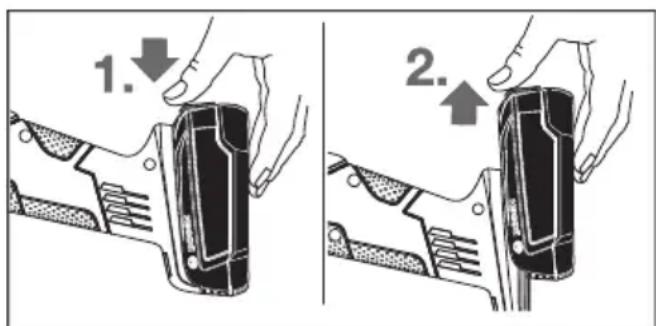
BnmaHna akymyIaTopa
Uo6 BnTgTH aKymyIaTOPhy 6aTaapeo (6),HaTNCiThBa KaHONky po3bLOkYBaHHra (8)iBnTfHiB aKymyIaTOPhy 6aTaapeo 3 eNeKTpOIHcTpymeHTa. He 3actocobyTe npu cboMy cnny.
IHHKAtop3apAKeHocTi
IHNkATOP 3apJxHeOCTaKymyTOpHOi 6atapei (5) NOKa3ye npn HAnoNobHy a60 NOBHiCTIO HaTHCHyTOMY BmHKaui (4) IpoTROM KeiNbKOx CeKyHd CTah 3apJxHeOCTaKymyTOpHOi 6atapei i Mae 33eJIeHi CBITNOjIoDN.
CbitnoioaEMnictb
He BnKOpNcToBMyTe nouKOJKeHy doaTkOBy pyKoTky.
3axnCTdnypykn
Дяpo60r3rmyoIO onopHOU wliyBaIbHOU tapinkoIO (19) a60 3aawkoBOU uITKOIO/AnCKOBOU uITKOIO/BiINONODHM Kpyrom 3abXdN MOHTyIte 3axnCT dny pyk (18).
3aKpInHIOHe 3axnCT nIpyk (18) 3aDOnOMorIO IOdaTkoBOi pyKoRTKn (9).
MoHTaX WniciyBaIbHnx po6oHx iHcTpymeHtIB
Ipeyimamahinyia3eneKtpoiHctpymeHTOM (hnp.,TexhiHm 06cnyroByBaHHa,3amHO pOboOoro iHcTpymeHaToo),aTakox npn HOro TpaHcnopTybaHHi 36epirAHHi BnMaHte akymytoPhy 6batapeo 3eneKtpoiHcTpymeHTy.Ipn HeHaBMCHomy BKIOUeHHI BnMkaa icHy eHe6eNeKa nopaHeHH.
He TopkaTeca unipybanbHnx a6o BiDpi3Hnx Kpyrib, NOK BOHN He OXOHOHTb. KpyrncnBHO HarpiaOTbcn iud yac po60tN.
OuHCTIb WlifyBaIbHN WnIHdEnb (17) i Bci npHaueHi dna MoTAtKy Detani.
Ipn MoNTaxi i DeMOHTaxi IiipyBaIbHnx po6OuNX IHCTpyMeHTIB HATNCITb Ha φikcatop WnHdEe (2), 0o6 3aipKcyBaTH WlipyBaIbHn WnHdEeB.
Iepu, hix haTnckataH na fikcaTop uHHdela, 3auekaite, nokn wniipybaIbHn uHHdelenb He 3yHHntbcra! B iHOMy pa3i eneKtpoiHCTpyMeHT MOKe NOsKOJNTHC.
UliyBaIbHn/BiPi3Hn Kpyr
3BaXaIte Ha po3mipn 7niΦyBaIbHnx po6OuHX iHCTpyMeHTIB. OTrBip 3a diAmETpOM Mae nacyBaTHdo onOpHoro fHaunr. He BnKOpNCToByTe aAnTepn a6o nepexiHNKn.
PnB BnKOpHCTAHNI AnMa3HNX BiDpi3HNX KpyRiB CnIkyTe 3a Tm, uo6 cTpiKa HAnpMky ObeptHaHa anMa3Homy BiDpi3HOMy Kpy3i BiNIObIana Ha npMky ObeptHaH eEeKtpoiHcTpymeHTa (INB. cTpiKy HAnpMky ObeptHaHa Kopnyci).
IocniIOBHiCTb MOHTaKy 3o6paKeHa Ha cToPiHci 3 MaIOHKamn.
ДязakpinneHЯшiФуBaIbHoro/BiDiP3Horo Kpyra BnKOpNCTOByIte WbNkO3aTnCKHy raIky (16) 6e3 6yDb- RAkx IHCTpyMeHTIB.
ⅢBnIko3aTnckHy raNky (16)do3BOJnEtbcBnKOpHcTObYBaTH NHe dNn WnIΦyBaIbHNx a60 BiDpi3HNx KpyrIB.
BnKOpHcTObyTe NHe 6e3dOraHHy, HEnoWkoJKeHy WbNdkO3aTHCkHy raKy (16).
Pn 3akpyuBaHHi cnikkyte 3a Tm, o6 MapkipoBaHa cToPOHa WbNdko3aTHckHoi raKn (16) He dNBnacn Ha wniΦyBaIbHn Kpyr.
ДяЗakpinenneHЯшлcfybanbHoro/biDiPI3Horo Kpyra BHKOpncTOByte BKNIOUHOdoaHy WBNKo3aTHCKHy raKy (16).
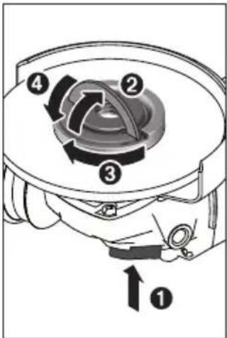
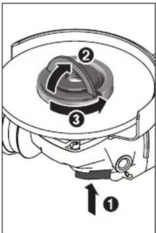
06iDnCKa He e DocTahim.
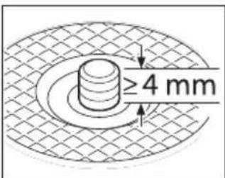
KIIIOUpiIDBaOTBOpN.
HaTnCHtB Ha φikcaTop
HnnHdEa (2), 106
3aΦikCyBaTH
HniΦyBaIbHN HnHdEb.
Ira 3aTaIrHeHH
WBnDKo3aTHCkHOi RaKN
(16)PiHIMiB cKo6y
WBnDKo3aTHCkHOi RaKN
OroPn i 3 CnIO
npOBepHtB
WBnDKo3aTHCkHy RaKy 3a
CTpIKKO Io RoINHHka.
OnycItb cKo6y dN
φikcaui WBnDKo3aTHCkHOi
raKn . 3aTHcKaHHa 3a
IpaBnBHO 3aTgHeHy, HeoNtKoJxHcy WBNKO3aTNCHy raKy (16) MoXHa BiDnyCTHTN BiD pyKn. DnIy cboRIO nIHIMITb CkOBy WBNKO3aTNCKHOI raKn DoROpn i 3 cnloI npOBepHtB WBNKO3aTNCKHy raKy npOTn CTpIKN rOINHHKa. HikoN He BiKpyuYte WBNKO3aTNCKHy raKy, Rka CnNTb DyXe MiHo, 3a DOlOMOrO IHcTpymeHa - BHKOPNcTOByTe pIKKOBn
Iicna MoTacky onOpHoro
pHaanu i wliyBaIbHoro/
Bip3Horo Kpyra Bilha
pi3b6a Ha wliyBaIbHOMy
wnHdieni NOBHnA
cknaDATn He MeHue 4 MM.
CniKyuTe 3a MiHicTHo
NoCaN WliyBaIbHoro
iHCTpymeHTa, 06 Bn He BiKpyTBCB Bid WnHdJI niJ qac Bn6iy eNEkTpoHCTpymeHTa.
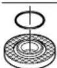
BOnopHOMyФlaHci(11)Ha ceHTpyOuyOMy nOracky 3NaXoNtbcra NpactMaCoBa DeTaNb (KInbce KpyrIoro nepepi3y).AkuO Kinbua KpyrIoro nepepi3y Hema a6o BOHO nowkodxe,OnOpHnΦlaHeuB(11)
Heo6xioHO 06OB'a3KOBO 3aMIHTnpeepnoaJIbIIMBVKOPNCtAHHM.
Picra MoTacky wNiyBaHbHO iHcTpymeHTa, nepu HIX BMHKATn npnad, nepeBipTe, u npabHbHO BMOHTOBAHm wNiyBaHbHm iHcTpymeT iu BinbHo Bin MOKe o6epTaTHc. BneBHITbc, 0o WNIiyBaHbHm iHcTpymeT He 3auinae 3axncn Koxyx a6o inwi detani.
BiaIonoi6HnI uIiOyBaIbHn Kpyr
Дяpo60Tu 3BiaHnoiδHmKpyrom 3aBXdmoHTyIe 3axnctIЯ pyk (18).
Tymobn tapinactn wniifybalbnn kpyr
Дяpo6it3rmyOBHMTapinuactHmUniyBaIbHmKpyrom(19)3aBXdMOHTyTe 3axnctJnypK(18).
IocniIOBHiCTb MOHTaKy 3o6paXeHa Ha CTopiHci 3 MaJIHOHKaMH.
HadiNbTe rymoby onopHy wniifyBaIbHy tapiKy (19)Ha wniifyBaIbHn WnnHdIb (17).
ПиТСНИТьшлфуВальнушКУРКY(20)MiцноДо HNXHbOrO bOKу rymoboi onophoIшлфуВальhoeTapINK(19).
HaKpyTtB Kpyrny raKy (21) i 3aTyrHtB ii 3a DonomorOo pIKKOBO rKnOu a nDba OTbOpn.
UaikOBA/ДИСКОВA uITKa
Дяpo60Tu3aUkoBOIOa6OuNCKOBOUuTkoU 3aBXnBCTaHOBNIouTe3axHcTJpyK(18).
IocniIOBHiCTb MOHTaKy 3o6paXeHa Ha cTopiHci 3 MaJIIOHKaMn.
UaKoBy/DnCKOBy 1tky noTpi6HO hakpyBaTH Ha UliCyBaIbHNI uHHDeIb HAcTIbKn, 0o6 BOHa uINbHO npIraIaDo oIaanuZ uIiCyBaIbHO rO uINHdJIeB KInci pi3b6N. MiIcH 3aTgHiTB uAikOBy/DnCKOBy 1tKy BnIKOBm raIKOBHM KIOUcEM.
TbePdoCnabHn qaIKOBn dNCK
BnKOpHCTOByBaTH qaIKOBH dNCK Do3BOJAEbC Hnwe pa3OM 3 BiIDNOBIDHM 3axNCHM KOxyXOM.
D03B0neHi wniifyBaIbhi iHcTpymeHTn
D03B0JIaTebCa BHKOpHcTOByBaTH yci Ha3BaHi B ciH iHCTpyKcII WlifyBaJIbHi iHCTpyMeHTn.
IOnyctHMa yactota o6epTaHHa [XBn] .1] a6o KonoBa WbNkictb [M/c] BHKOpncTOByBaHNx WnIcYBaNbHnx IHCTpyMeHTIB Mae npHaMHi BiNIOBjDaTH daHm, 3a3HaueHm B HnKcpeNoaHi Ta6nci.
3 uei npuHH 3BaJaHe Ha donyctmy qactory o6epTnHa 6o KOnOBy WbNdkicTB, 3a3HaueHl Ha etHKeTu iWlifyBaIbHoro IHCTpyMeHTa.
| м akс. [MM] [MM] | ||||
| D b d [хвил. | -1] [M/c] | |||
| b | 115 | 7 | 22,2 | 11500 80 |
| 125 | 7 | 22,2 | 11500 80 | |
| D | 115 | - | - | 11500 80 |
| 125 | - | - | 11500 80 | |
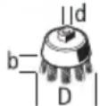
7530M141150045
BicmOKTyBaHHnHy/Tnpch/ctpyxKn
Питaknx MaTepiJIb,ЯнHap.,Якофар6OBHX NOKpNTb, ⅢO MICTaTb CBnHeCb,ДeяKnx BnIDBdepeBnH,MIhepaJIb i MeTaNy,Можe 6tN He6e3neuHm DnIg 3DopOB'.TopKaHH a6o BnXaHHaNMy MoKe BnKnKaTu y Bac a6o y oci6,io 3NaXoJrTaBcNoBn3y,anepriHi peakii Ta/a60 3axBOpUBoHHaNxaJIbHx WnIaXiB.
IeBHI BnI Nny,ЯK HAp.,dy6OBn a6o 6yKOBn nI, BBaKaIObCra KaHcePOReHHMn,OC6bNBO B cNoIyueHHi 3do6aBkAmn DnI O6p6Kn DepeBHN (xPOMaT,3ac6bN dIg 3axNCtY DepeBHN).MATEPIAn,IO MCTaTB a36ecT, Do3BOJNAETbcr O6p6JIaTI NIIe CneuianicTaM.
- CπiδκγηTe 3a Φδροιν ΒeHTnλημείη Na pɔδούmγ mιςι.
- PekomeHnyetbcBdraTn pecnPapOpHy macky 3 φiNbTpom Knacy P2.
Iodepknyteca npnncib 0do o6po6noBaHnx MaTepiaiB, 0o diotb y Bauii kpaiiHi.
YHKaTe HAKOnHueHHaHny Ha po6Omy Mici. MoKe JERKO 3aIMaTnCra.
Po6ota
PouaToK po6OtN
BctpomnHHa akymnatopHO6atapei
BcTpOMt b3apJxHn aKymyIaTOp (6) B HixKy eNeKTpoIHCTpyMeHTa, 06 aKymyIaTOp do6pe 3aΦikcyBaBCr.
BMKaHHBmKahH
Uo6 yBIMKHyTN eneKtpoiHcTpymENT, nocyHbTe BmHKa4 (4) Bnepei.
1063aΦikcyBn BmHKa4)HaTCHtB Ha BmHKa4)Bnepei Bn3 Tak, 06 Bin yBiWb y3aenHHe.
Iio6 BHMKHYH eNeKtpoiHCTpyMeHT, BiDnyCtITb BUMKaU (4) a6o, RaKIO BIn 3aFikCoBaHn, KOpTko HaTNCHTB BIMNKaU (4) HaaI i Bn3 i TOni BiDnyCtITb NOrO.
Ipeed BnKOpHCTaHHMa nepeBipIe Te wliFyBaIbHi IHcTpymEtN. lniFyBaIbHi po6oHi IHcTpymEtN MaIOb 6yTH 6e3DorAHHO MOHToBAHI i BInHo NOBeptaTncs. 3dIChITb np6he yBIMKHeHH npHaMHi Ha 1 XBmHy 6e3 HabaHTaxKeHH. He BnKOpHCTOByTe NoXKOJKeHi, HepiBHi WNIΦyBaIbHi IHcTpymEtN a60 Taki, 00 Bi6pyTo. NoiKoJKeHi po6oHi IHcTpymEtN Moxyt b LaMaTncs i cnpuHHTn TiIecHi yWkoJKeHH.
3axnCT BiN NOBTOPOIycky
3axnCT BiNIOBTOPHORO ncyk 3anobirae
HeKoHTpOJIbOBAHOMy 3anyCky eNEKTpOIHCTpyMeHTy nICnI nepe6oIB 3 eNEKTpONocTaaHHaM.
U063HOByyBIMKHTn eNEKTPOIHCTpymeHT, BIMKHTb BIMNKa4 (4) i3HOBy yBIMKHTb eNEKTPOIHCTpymeHT.
NocriHa eIeKtrponika
NocTHa eNeKToPiKa 3a6e3neUe MaJxke OndaKoBy KInbKiCTb o6eptiB npn po60ti Ha xOnocToMy xOdy i nid
HabaHTaKeHHaM; 3a6e3neUc piBHomipHy npOdyKTnBHicTb.
PnabHnn nyck
EneKtpoHa cNCTema PnABHOrO nycKy o6Mexkye 06epTaIbHm MOMENT pRn BKNIOueHHI Ta 36iNbUyE CTpOK ekCnIyatauII MOTopa.
BctahOBJENHKnIbKocti 06epTIB
3a donomoroKoIiataKdBCTaHOBHeHKeIbKOcTi o6eptIB (7) MoXHa BCTaHOBnOBaTH Heo6xIDHy KInbKiCTb o6eptIB, taokn iac po60TN. DaHI, 1O MICTbCB R HnXueNoDaHt TabNci,-nHwe peKoMeHdaJia.
IiKyTOM BCTaHOBHeHH BID 30^ Do 40^ npn O6dnpHomy
WNIΦyBaHHI DocraTbCn HauKpaun pe3yNbTaT
O6pO6JIeHH. NIOoBtBe eNEKTPOIHCTpyMeHTom Ha3a i
Bnpeq,HaTNCKaUOn Ha HbOrO 3 OndAkoBOIO CnIOIO.
3aBDAKN cboMy o6pO6NtOBaHa 3aGTOBka He 6yde
nepeRpiBaTHc, He 3MiHHTb CBOei φap6n i Ha Hi He
YTBOPHTCBc CMyXOK.
Bianonoadi6nuiybalhnykpyr
BiarnonoibHm wliyBaIbHM kpyrom (npnaJa) moKHa
Takox obpo6nrtn BnHyti nobepxhi i npophi.
BiarnonoibHi wliyBaIbHI kpyrMaIOb 3HaUHO IOBUni
ekcnlyatauiHn pecypc, cnpruHHaIOb MeHwe uMy i
MaIOb HIXcy TeMpepaTy wliyBaHHra HIX TpaHciHi
wliyBaIbHI kpyr.
Pozpi3aHHMeTany
Дяpo3pi3aHHaDonomoroIO 3B'ra3aHOro a6pa3nBy Heo6xioBVKOpncTOyBaTH 3axnchN KOxyX JЯ po3pi3aHHa (13).
PnB BiDpi3aHHI npaioTe 3 NOpHIM npocyBaHHAM
po6oOro iNCTpyMeHTa y BiNObiHocTi Do o6pObIOBaHO
MaTepiany. He HATsCKaIte Ha BiDiPI3HN Kpyr, He
pekeoWyIte Ioro i He XHTaIte Ioro.
IicnBmKHeHHn npnaHy He raIbMyTe BiDpiHn KpynpNTnCKaHHM 360ky.
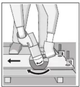
EneKtpoiHcTpymeHT
noTpi6Ho 3aBxdi
BVKOpNCtOByBaTH npOTn
HaNPmky o6epTaHH.
IHaKwe icHy eHe6e3NeKa
HEKOHTPOlbOBAHO
BnPBaHH i3 npopi3y.
Pp no3pi3aHHi npophiINiB
KBaDpaTHnx Tpy6 Kpaue
NouHaTHn 3 HaMeHbWoTO
nepepi3y.
P03pi3aHHKaMeHIO (nVB.MaI.A)
P03pi3aHHKaMeHIO Heo6xIDHO 3a6e3neHTN DOCTaTHBicMOKTyBaHHH Nnny.
BdraaTe nno3axnchy macky.
EneKtpoinhctpymentdo3B0nAeTbCBAHKOPHCTOByBaTHnnne dna cyxoro po3pi3aHH/cyxoro wniifybaHH.
Ipyo3pi3aHHKaMeHIO Kpaue BnKOpncTOByBaTH aIma3HbBip3Hn Kpyr.
PnBnBnKOpNCTaHHI BNTJXHOrO KOBnaka dny po3piHaHHa 3 IIOHeTHm CyNOpTOM (24) NIOOCoc NOBHeH 6yTN DoNyUeHM DnB BiDCMOKtYBaHHa Kam'HOrO nHly. Bosch npOnOHye npHaDHi NIOOCoch.
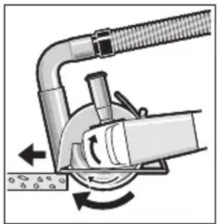
YBIMKHiTb
eNEKtpoiHCTpyMeHTi
nPNCTabTe NOro
nepeHbOu qACTNHO
HaPmHNx cAla30k Do
obp6NoBaHOi 3arOTOBKn.
IpcyBaIte
eNEKtpoiHCTpyMeHT i3
nomipHOIO nOaueyo
BIDNOiDnOcTi Do
obp6NoBaHo
MaTepiany.
Pnpo3pi3aHHIO6bNBO TBepnX MaTepiAIB,HaNP.
BetoHy 3 BnCOKIM BMICTOM raIbKn, aIma3HNI BIDpi3HNI
KpyrMOKe IpeerPiBaTNCs, IO npn3BOOHTb DO HOro
nowKOJKeHN. Pno ce HeB03NaHO CBIuHTb BiHeCb i3
ickop HaBkoI OAma3HOrO BIDpi3HOrO Kpyra.
Ytakomy BnnaKny npnnHnHiTb po3pi3aHH Ta daIte
anMa3HOMy BiDpI3HOMy KpyrO oxoHOHTN, DaBUn HOMy
npOTROM KOpOTKOro Yacy NoppaIOBaTH Na XOIOCTOMy XOdy
Pn MaKcHmAbHiN KInbKocTi o6epTIB.
3Haune 3MeHsEHn npOdyKTHBHOCTi pO6oTH i 3Hauna Kaibkictb icKop cBiUcaTb npo 3aTyPHeHH aIma3HOro BiPi3HOrO Kpyra. Bm MoXeTe 3HOB HaOCTpHTN Horo, 3pObUnn Kopotki NaP3N B a6pa3NBHomy MaTepiAn, Hanp., y CnIkaTHi UerNI.
Bka3iBkn 0oDo cTaTnKn
WluiB Hecuynx CTiHax NiIyraHOb CTaHapTy DIN 1053 u. 1 a6o HaioHaIbHm npnncam. Ux npnnnciB noTpi6Ho o6OB'8KOBO DoepKByBatncr. 3 icE i npnuHH nepei no4aTKOM po6OTH Heo6XiHO OTPMaTH KOHCytBaIIO BID BiNobiHorO cneiaJIcTa 3i CtaIKu, apXiteKToppa a6o npopaba.
Bka3iBKn 0oOOnTmAbhHOro NOBODKeHHa akymyIATOpom
3axnauTe akyMnyTOp BID BOJOrn i BoN.
36epiraTe akymyIaTOp InIe 3a Tempeatpyn BiD -20°C Do 50^ 3okpema, He 3aIIHsaIte akymyIaTOp BnITky B MaunHi.
Yac BID Yacy npouhzaJe Te BeHTnlaui Hi OTBOpn aKymyIaTopa M'kHM, UHCTHM i CyXM NeH3JIHKOM.
3aHaTTO KOPOTKa TpNBAJIcTb PO6OTn NICr 3apJXaHHcBIDHTb Ipo Te, IIO akymyIaTOP BvpePnaB ce6e i Noro Tpe6a NOMIHATN.
3BaKaITe Ha BkAizBKNIIOO BnDAneHHN.
Texhuihe 06cnyroByBaHHaicepBic
Texhiue 06cnyroByBaHH i ouuueHH
Ipeed ycima maHinyuaizm3 eNeKtpoiHCTpyMeHTOM (hanp.,TexHicHHM 06CnyROyBaHHaM,3amHOIO pObooro iHCTpyMeHaToo),a TakoX npu Horo TpaHCnOpTyBaHHi 36epirAHHi BnMaIte akymyTOpHy 6atapeo 3 eNeKtpoiHCTpyMeHTy. Pn HeHaBMCHOMY BKJIoueHHI BnMHKaaya icHy eHe6e3neka nopaHeHHa.
Дяякісоіi 6e3neuhoi po60Tu Tpmaite enektpponpnaia i BeHTnlauiHi OTbOpN B uHcToTi.
AkypatHO 36epiraTe npnnaT Ta akypatHO NOBObTEcH Hm.
Cepbic KOHCyNbTauii 3nHTaHb 3actocyBaHHA
B cepbichm MaCtepHi Bn OTPMaTe BiNobiNb Ha BaWi 3aHTAHH CTOCOBHO peMOHTy i TexHcHoro OcbNyTObYBaHH BaWOro npOkykTy. ManIOHNK B DeTAnx i INOpMaIIO 0do 3aunactNH MoXHa 3HaHTN 3a aIpecoIO: www.bosch-pt.com KomaHa cPiBpObitHKIB Bosch 3 HadaHn KOncynbTaui NDo BVNKOPHCTAHN pOdykuii i3 ZAOBOJENHM BiNOBicb Ha BaWi 3aHTAHH CTOCOBHO hAoI npOdykuii Ta npHnadJa Do Hei.
Pn BCx DoaTKBHX 3aHTAHHx Ta 3aMOBHeHHi 3aNactH,
6yNb NaCKa, 3aHaayte 10-3NaHn Hmep dny
3aMOBHeHH, 1o CToITb Ha nacnpTHi Ta6nui npOdykTy.
IapaHTiHne 0cncyroBvBaHH i peMOHT eNEKtpoiHCTpyMeHTy
3diCHIOUBcBcB DINOBIHO DO BVMOR I HopM BNTOBIOBAuHa TepntopBcix KpaIH NIIe y fipMOBHX a6o
ABTOPH3OBAHnx cepBicHNx CEHTpax fipMn «Po6epT BoW'.
PONPEJXEHH! BnKOpNCtAHNkoHTpaKaKTHOi npOdykii
He6e3neueH BekCnPyatauCiIM oMoKe MaTH HeTaNBH i HacNiDkn
dIra 3dopOB'. BnROTOBHeHH i pO3NOBcIOnJeHH
KOHTpaKaTHOI npOdyKUII nepeCNIyEYtbcS 3a 3aKOH M B
aDMHicTpAIBHOMy I KPMiHaJIbHOMy nopAky.
YkpaHa
Bou CepBicnIeHTpeEneKtpoiHCTpyMeHTiB Byn.KpaHr1
02660 KIIB 60
Ten.: +380 44 490 2407
a c: + 380445120591
E-Mail: pt-service@ua.bosch.com
www.bosch-professional.com/ua/uk
Adepea PeriohaBHNx rapaHTiHnX cepbichnx MaicTepeh6 3a-3HaueHa B HaioHaBHomy rapaHTiHOMy TaIOHi.
Adepcnihnx cepbichnx ceHTpiHabeedeHO Hxue:
www.bosch-pt.com/serviceaddresses
TpaHcnpTyBaHHa
HaДоанi litieBO-ioHHi akymlyaTOpHi 6aTapei
po3IOBcIoxKyIOTcBnBMOrn IooTO TpaHcNOpTyBaHH
He6e3neuHnx BaHTaxKiB. AkymlyaTOpHi 6aTapei MoKyTu
NepeBO3NTncKopNCtYBaayem ABTOM6iNbHM TpaHCnOpTom
6e3Notpe6n BkOHaHHNoDAtKOBHX HOpM.
Ipnpecnui Tpeimn Oocamn (Haep.: nobitpHmmpaHcnpotom a6o TpaHcnpotHM eKcneHtOpom) nOtpiHo 0doepkByBaTHCnOc6bHNBHX BMO rOo ynaKOBKn TaMapkyBaHH. Ycbomy BNnAky NIOrTOBci Nocnkn NobHHen 6paTn yuactb EKcNep3 He6e3neuHx BaHTaXIB.
BicnnaTe akyMnyTopHy 6atapeo nIwe 3 HeNouKoJKeHm Kopnycom. 3aKeNeTe Bdkpnti KoHTaKTn Ta 3anaKyTe akyMnyTopHy 6atapeo TAK, 0b BOHa He COBaJaCBy ynaKOBci. DToPmYtec, 6yNb NaCKa, TaKOx MoXnBHX DoTaKOBHX HaioHaIbHnx npnnnciB.
Ytuniauia

EneKtpoPnpnlaH, akymyTOpHi 6aTaapei, npnaIpy I ynaKOBky Tpe6a 3daBAtn Ha ekonorIHO qHCTy nobToPhy nepepo6Ky.
He BnKdAaTe eNeKtpoPpnaT Ta aKyMylrTopHi 6aTaapei/6aTaapeeKn B no6yToBe cmITr!
Jnue nKpaH EC:
BidiobioHdoEbponecboiDnpeKTbnu2012/19/EU eKeTpoiHCTpyMeHTN,IO BniuN i3BXNBaHHa, Ta BiIOBIOHOEOBPonecboiDnpEeKTHNu2006/66/EC nowkoJxehi a6o BiipauBoHa iakymyItopHi bataei/ baapei/ baapekn NobHHi 3daBaTncs OkpemO i ytni3yBatncs ekolorgno HcTm Cnocobom.
Akymnyatopn/6aTapeien:
JitieBO-ioHHI:
ByNb Iacka, 3BaXaIte Ha Bka3iBKn B po3diI TpaHCnOpTyBaHHN (INB. ,TpaHCnOpTyBaHHN CtopiHa 200).
Ka3ak
Eypa3nЯ ekOHOMNKaIbIK OdafbiHa (Keeden OdafbiHa) Mywe MemlekeTepayMaftbIHda
KoIdaHbInaIbI
THdpuyinH OHIM YwH Kapactbipfah naDanahy KxKaTApbHbH KypaMbHa naDanaHy XeHiDei OcbI HcaybIK, COhBMeH bipre KocBIManap da bonyMymKIn.
Caikeci piactay kaiNbI aKnapat KocbIMwada 6ap.
EHIMDi eHdipreH Memleket TypaIbI aKnapat EHMHH
KopnycbIHda XeHe KocbIMwada KepcetinreH.
EHdpinreH mep3imi HycaynbIK MykaabcbIH COHbfI 6etihde KepcetireH.
HmnpTepre KaTbICTb 6aHaNbIC aKnapaT eHIM KaNTaMaCbIHda KepcetinreH.
Thimi nai danany Mep3imi
OhimHH Kbi3MeT ety MEPiMi 7 Kbl. OHdpinreH MEPimHebactan (OHipy KyHi 3aybit TaKtaaAsbHa Jka3bIHaH)
icteTne 5 kbl caKtafahHaH coH, eHimDi TeKcepyci3 (cepBnctik TeKcepy) naIdaNaHy ycblnMaIbI.
KepceTinreH Kbi3MeT ety Mep3iMi TyTbHyIbI aTaIMbI HYCKayIbIKbIH TaIaNTapBbI OHOpbIHdaFaH XaFdaIa FaHa JkapamDbI 60anaBl.
ICTEHwbyfce6entepinHti3iM
KeYUWKbIH UbIKca,naIaHaHbI3
KaTbI dpiin Ke3iHne naHaan6aHbI3
- TOK, cblmb 6y3bIFaH Hemece OKuaynaycbi3 60nca, naDanaHa6aHbI3
-0HIM KopnycbiHaN TiKeNe T TyTIN bIka, naJaIaNbHaB13
PaiDanaHybIbH, MymKIn KaTeiKTepi
-TyTKacbI MeH Kopnycbl 6y3bIFaH 6oNca, EHIIMi naJdaHaH6aHbI3
JaybIH-wwbHKe3iHne cbiPTa naIdaIah6aHb3
- Kopnyc iuihe cy kipce KypbIFbHbKocyu b6oMaHb3
Wektky6enrinepi
-TOKCbIMbIHbHTO3yblHEMeCE3aKbIMdAHybl
-0HIM KOpNycbIbIH 3aKbIMdAlybl
KbI3MeT Kepcety Typi MeH xiniriri
-0p naIdaIaIahc coH eHIMI Ta3aIay ycbHbIaNbl.
CaKray
Kypfak Kepde caKay KepeK
KOFapbI TemnepaTypa Ke3iHe HKeH KYN CaynepePiH acepiHeH anbc caTay kepe
- caTay Ke3iHne TemnepaTypaHbIH KeHeT ayblKybiHaH KopFay KepeK
- opamacbi3 caKtay MymKiH emec
- caTay wapTapbI TypaIbIKocbIMwa aKnapaT any yuH MEMCT 15150-69 (wapT 1) KxKaTbIH KapaHb3
- +5-дeн +40°C-кa дeин Temператураьнда Коимада
eHдірушін KaNTamacbIHДа calKaTHbI3. CalbɪcTBɪpMaJIbɪ
bɪnfaɪdʌblɪbɪk 80% -дан acnaybl Tɪnic.
Tacbimanay
TacbImaIay Ke3IHDe eHIMDi KynatYfKa XHe Ke3 KeIReH MExaHKnblk bIKnAe TyeKe KaTaH TbIbIM caIbHaDbI
-6ocatyjkykTey Ke3iHne NaKeTTi KbicaTbH MaunHaapdbi naDanahyFa pyKcat 6epimEni
-TacbImaIay wapTapbTaIanTapbIH MEMCT 15150-69 (5wapT)KyKaTbIH OKblHbI3
-KopshaFAn opTa TemnepaTypacbl-50 ^ C TaH +50^ Ka DeiH TacbImaIay pyKcat etinreH. CaIbIcTbIpMaIbI bInFaIdbIbIK 100%-daH acnaybl Tnic.
Kayinci3dk HycKaynapbl
Kannbl 3nektp kypandbi kayinci3dk HycKaynapbl
ECKEPTY
Bapnbik kayinci3dknyckaynbikTapbIH XaHe
eckeptneepiokbih3. Texnkaibk kayinciik HcaynbTapbiH kHe eceptneepdi caKtMay TOKtbH
coFybiHa, opt KHe/Hemece aybip kapaKaTTaHynapFa aIbIn KeIyi MymKiH.
Bonaawk kymbictap yuih kayinciik hycaynbiktapbi Me h ckeptnenepei caKan Koibih3.
Kayinci3ik HcyckaynbkTapbHna naDanaHbJFaH 3neKtp KypaI aTaybHbH JeIeH Kyat aNaTbH 3neKtp KypaIapbHa (KeIinIK KaBeni MeHe) XeH e AkyMnyTopdH Kyat aNaTbH 3neKtp KypaIapbHa (KeIinIK KaBeni KOK) KaTbCblbap.
XymbicophbiHbIHkayinci3di
KymbocpHbIH Ta3a XHe KApbIK YcTaHbI. NaCTAHFaH XHe KaPAHfBI KaINapDa cTcI3 OKnFAnap 6Onybl MyMKiH.
3NeKtp Kypblfbcih XkapbIaTbIH aTMocepapa naHdaanhaHbI3, MbICaNbl, XHaTaBH cyhblIK, ra3 Hemece waH 6ap 6onFaHa.3NeKtp Kypal yWKBiHApdbI XacaHbI, an Onap WAn Hemece 6ynapdbI XaHDbpybl MVMKH.
Bananap men 6aKbInayuBnapdp3neKtp KypanbHaH anbc yctahbi3. AndaHynap 6aKbInay XofanybHa aIbIn Kenyi MymkiH.
Ka6bIK TpyMbICTbIK XaFdaInapda, KOMMepuIbIK aMaKTapda XHe KOfAmdbIK XepIepde, 3HnDbI XHe kayinti eHdpictik paKTopnapXoK KIIi 3neKtp TytbHybI 6ap eHdpictik aMaKTapbIHda XyMbIC icTey ywiH apHaIraH.
3neKtpKayincizdiri
3NeKtp aHbIpapbI po3eTKaFa ca6oynbl Tnic. AHybIpyeWkaaH eWkaHdaTepi3e 03reptneHi3. Xepre KocbInFaH 3NeKtp KypanlApBIme H aanTep aHbIpapbIH naDanaH6aHbI3. 03reptinMeReH aHybIpap MeH caikec po3eTKaIap 3NeKtp TYbIKaTybIH KayinIH TeMeHndTeJI.
Ky6bipnap,paadnTopnap,nnntanap Meh cybITkbIHTap cnAaTbI Jepre KocbInfah 6eTTepre TImeni. DeHeH3 Xepre KocbInfah 6oJca Xofapbl TOK cOfy Kayini naJa 6oJadbl.
3neKtp KypaIapdbI XaH6bIpda HeMece bINrAnDbI KopwaYda naIaIaN6aHbI3. 3neKtp KypaJIbHa KipreH cy ToK,coFy KayinIH XoFapblNaTaDbI.
Kabebdi Tnicti 6onmaH pette naDanaH6aHbI3. Kaebdi 3neKtp KypanbIn Tacy, KeTepy Hemece ToKtah wBIFapy ywiH naDanaH6aHbI3. Kaebdi bICTbIKM, MaH, oTKip KbIPnap XHe XbIMaHbI 6eKeTepdeH anbc YcTaMaHbI3. 3aKbIMdFaH Hemece 6blcIn KeTkeH Kaebb Tok cFy KayinIH KOfapblNaTAbI.
3NeKtp KypalbIH cbIpTaNaiDanaHFaHda cbIpTkblXaInap yuiin caN Ka6enbdi naiDanaHbIb3.CbIPTa naIdanaHyfa XapaMbl Ka6enbdi naiDanaHy TOKcofky KayiniH TeMeHneiDi.
Erep3neKtp KypanbIH bINrAnDbI JKepe naJdanaHy Kepek 6oNca,Onda KopraTbIH eWipy KypblfbcI (RCD) apKbIbI KoprFaRrA H TOK XeNicin naJdanaHbIB3.RCD naJdanaHy ToK cofy Kayinih TeMeHJeTeJI.
KekeKayinci3ik
3NeKtp KypanbI naHaIaHya a6aB 60nbHb3, XyMbICbIHbI3bI 6aKbIaHbI 3XaHe npacATbI naIdaIahbIbI. 3NeKtp Kypanbl wapwaFAn Ke3de Hemece eciptKI, ankoronb Hemece dapi acep etKeH Ke3de naIdaIah6aHbI. 3NeKtp Kypanbl naIdaIaHy Ke3IHde aHcbl3bIK aybIp XeKe JapaKaTTaHyf aIbIN KeNyi MymKiH.
Keke KopraTbIH Kaa6dbkTapdbi NaaHaanahbHbI3. Opaabim Ke3 KopraHbcih TaBbI3. HaMaCKacbl, cbipraH6aaiTbIH Kayincizik aK KIMdepi, Wnem Hemece ecty KopFaHbIITapbl CNKrTb I KoprafbIJ Xa6DbIKTapbl TnicjXaFdaInapda KonJaHbIN Keke JapaKaTTaHynapbl KemeiTepi.
Ke3eKcK icke KocbIydbH anDbH any. Tok Ke3iHe XaHe/Hemec 6aTapeanap XHaHafbHa KocyaH anDbH, KypaNbI KTepy Hemece TacydAn anDbH oipriw eik Kynde 60nybHa Ke3 JeTkizhi3. 3JeKtp KypaNbIH CaycaKtbl eipriuike KoBnTacy Hemece KockbIbI Kocybl 3NeKTP KypaNbIH TOKa Kocy cAtci3 OKFaRa aBn Kenyi MyMKIn.
3neKtp KypaBbH KocyaH anDbH KeIreH peTtey CbIHcBbH Hemece KITTI anBbIN KObIBbI3. 3neKtp KypaBbHbH aHaTaBH 6oJIrHDe KaIFaH KiIT Hemece CbHa JKeK JapaKaTTaHyFa anBbIN KeNyIMMKIH.
KoN KUw icTeTneH3. OpaBIM Tnicti TaHbI W neH TeH caJIMaKbITbJIKTbI CaKTAHbI3. Byn KytinMereH Jafdaanapda 3neKtp KypaIaNbIH BaKaIaNahyBH CaKTAIDbl.
Tnicti KIM KNIH3. Boc KNIM MEH OweKeinepdi KHMehi3. Wauhblb3dbI, KIMDi XHe KOIFantbl XblXbImaJIb6eKTEpeH aIbc yTaHbI3. Boc KNIMdep, OweKeinep HeMece y3bIH Wau XblXbImaJIb 6eWekTepe Taptbnkanybl MymKiH.
Erep wan wbiarpbnxHHay xa6dbikTapbHa Kocy Kypblfbnapbi bepnireh 6oNca, OHda onap Kocynbl 6onybHa Xehe Ticti peTte kondahybHa Ke3 XeTki3H3. WaH xHHaydbI naJaIaNHy waHa 6aIIaHbICTb 3INHdapDbI KeMeTeJI.
HA3AP AYDApblbI3! 3heprnmeH xa6dbkTaydbIH TObnkTaH He xekelne ToKtaTbIybi Hemece 3heprnmeH xa6dbkTaydbI backapy ti36erHH akaynahybi caandapbHaH 3neKtp KypaBbHbIH Kymbcihda Kiipic naJa 6oRan Jxafda, 6yfaTtAmarHdbfBHa Ka3 XeTKi3in (6oRan Jxafda) 6apbIn, axbpatkbWbIK. (Owipy) KaNNbHa KeTIpiH3. Xenilik awahbI po3eTkadaH 6bIFapbHbI3 Hemece anbIn - canMaBl aKKymyTAOpDbI axbipaTbHbI3. OcbpekeT apKblbI 6akblaHbAHTbH KaTAtcKe KocblydbH anDbH anacbl3.
AtanmbiPi naIaIaNHy XeHInIerI HyckaynbIka caikec 6iniKti Kbi3MeTkepNep KypambHa 3JeKtp Kypabln peTey, MOHTaJxay, KOJaHbICKa eHri3y XeHe OFaH KbI3Met KepceTy apeKeTTepIme TaHbIC TyfAnap KaTaIbl.
3NeKtp KypaBImeH KyMbIC icTeyre 18 Xacka TOnFaH, TexHNKaIbIK CnNaTTaMaHbl, naJaIaNHy XeHiHderi HcayIbIKtBi XeHe Kayinci3dik epexenepiH Okbln ShbIKKaH TyNfAnapra pyKcat erinei.
He He, ceim Hemece akbn-oi KaibineTepi WeKteyni Hemece Taxipnbeci MeH 6inimi XeTKiikci3 aamdap onapdbih Kayincidi rwiH kayantbI TyfahbIH 6akblaybHa 6oImaca Hemece 3neKtp KypalbH naDanahy 6oBbHnHa Hyckay anMaFah 6oJbIMdbi NaJaNaH6aybI Tnic.
3neKtp KypanapbH naiDanaHy XaHe KyTy
KypaIbI aca kon JyKTeMeH3. KymbIcbl3 ywiH Xapambl 3neKtp KypaIbIH naJaHaNbHbI3. Kapambl 3neKtp KypaIbIMeH kepeKTI JyMbIC aHaMaFbIHda dypbc api ceHimdi JyMbIC icTeHci3.
AxbipatKbIbI dypbc Emec 3neKtp Kypanbln naaH6aHbI3. Kocyfa HeMece eWipyre 6oMaTbH 3neKtp KypanblKayinti 6oBbIn, OHbl XeHdey KaXeT 6oJaBl.
Ka6dkTapDbpeTey,6nweKeTpih anMaTbipy Hemece KypanDbI anbIN KOIOHaH anDbIH aHbIPdbI pO3eTKaHaH WbIFapbIH3 XHe/Hemece aKKMyTAOpDbI anbIN TactaHbI3. Byn caKtbIK apeKeTi 3neKtp KypanDbIH bainKaycbI3 KocblNybiHa Konl bepMeiDi.
PnJaIaHbIMmaTbIH 3JKeKtp Kypanapdb6aIanaP KOblXeTTneTIN XaIra KOblHbI3. OcbIapdb6IImeiTIn Hemece ocbI ecepttnenepdi OkbImarah aamdpfa 6yn KypandbI naIaIaNyFa KonBepmei3.Taxipi6eci3 anaMap KOblHda 3JKeKtp KypanapblKayinti 6oIaBl.
3NeKtp KypaIapbIH ykbINTbI KYTIH3. Ko3rAImaB160neKtePepin Kepeprici icteyine XeHe KenTeiIN KaMaybHa, 60neKtePepin akaycbI3 Hemece 3aKbIMdAmarAH 6OlybHa, 3NeKtp KypaIbIH 3aKbIMdAmarAHbHa Ke3 XeTKi3H3. 3aKbIMdaFah 60neKtepi 6ap KypaIbI naDanaHydAn anDbH XeHDeH3. 3NeKtp KypaIapbIH dypbc Kytimeyi Jka3aTaiBIM OKfApra ce6en 6oJIbN XaTaIbI.
KeckiawacnanTapdbI eTkipxheTa3a Kynde caKaTahbI3. DypbckytinreH xHe Keckiw KneKtepi eTkip Keckiw acnanTap a3 KeNTeIn, KecinTeH 6eTke OHaH 6aBtTanaDbI.
3NeKtp KypalbIH, Xa6DbIKTapdbI, anMaIbI-canMaIbI acnantapdbI XeHe T.6. OcbI HycKaynapra cai naJaIaNbHbIbI3. CohBIMEN XyMbIC wapTTapbIMeH opbIHdaTbIH apKeETrep Ha3ap aydApbHbI3. 3NeKtp KypalapbIH apHaImafAH XyMbICTapda naJaIahy kayinti.
Batape KypanbH naiDanaHy XaHe Kyry
Tek ehipuyi cinnataraH 3apraTafbiWmeh KaTa 3apraTahb3. BaTapej KInHaftbHbH,6ip Typine caH 3apraTafbl6acka 6atapej KInHaftMeH KOndaHyda ept Kayinie aBbIn Kenyi MymKInH.
3NeKtp KypaIapbIH TeK apHaaiI TaarbiHdAnfah 6atape JxHaKTapbIMeH naJaIaNbHbHbI3.Ke3 KeIreH 6aca 6atape JxHaKTapbIH naJaIaNHy XapaKaTTaHy MeH ept Kayinihe anbln kecenei.
Erep 6atapera XHHarbl kondahyda 6oMaCa, OHbl tyipeiyu, TbH, KInT, Were, 6ypaHa HeMece 6acka kiwi Metan 3aTTapdAn yCTaHbI3, onap 6ip
TepMNHaIaHb6acKacbHa 6aJIaHbIC Xacaybl MyMKiH.
BaIape TepMNHaIapbIH Kocy KyIK Hemece optke aIbIn Kenyi MyMKiH.
Dypbc emec naandaHya 6aTapeaHaCybIKTBArbyi MymKIn, orAH TMHei3. Erep TnIN KAncaHbi3, Cymeh waiBnTactaHbi3. Erep cybIKTBK Ke3re TnCe dApirepre xaapnaCbIHbI3. BatapeaHaN WaaKaH CybIKTBK Ko3y HeMece KyikTepre anbln Keenyi MymKiH.
KbI3MeT Kepcety
3NeKtp KypaBbHa MaMaHDbI XeHDeywi TeK 6ipde KocankbI 6bnweKtepeMeH KbI3Met Kepcetyi Kepek. Byn 3NeKtp KypaBbIH Kayinci3irIH caKaTanybIH KaMTaMacbi3 etedi.
BypbIbTkTericTey MaunHapbH naJaAnaHy Ke3iHderi Kayinci3dk TexnKacbl
MaJdAnay, axapnay, cbIM KbIuBikneH Ta3aNay Hemece a6pa3NBti Kecy aictepi ywH Kayinci3dk HycKaynapbl
Byn 3neKtp KypanbMaiaNarbiw, axapnaRbiw, cbIMdbIK KbINWBiK HEmece Keckiw acnan peTHe naHdaHnyra apHanfAH. OcbI 3neKtp KypanbIHn HnHaRbHDArbI eckepTynepi, HcyKaynapdbI, cypeTepdi Xhe CnnaTTaMaIapDbIOkbIH3.Bapblk TexHnKaBik KayinciaDik HcCKaynbITapbIH opbIHamay TOKtbIH COfybHa, oP TxHe/Hemce aybip JapaKaTaHynapFa anbIN KenyIMMkiH.
XbIbIbIpaTy cNkTbI apeKeTTrepre Ocbl 3neKtp Kypanbl apHaImarAH. 3neKtp KypaIbHa apHaImarAH apeKeTTep 3nH, Kayin KeTIpin Xeke JapaKaTTaHyf aIbIn Kenyi MymKiH.
Acan oHdpywmeh kacammaH HeMece ycBn6aHaKepeK-kaPakTapDbI naDanaH6aHbI3.KepeK-kaPak3NEKTP KypalbHbI3ra cai KeIce De, Kayinc3 Xymbcic ictey KaMTamacbI3 etImmeNi.
Kymblc KypalbI aHaHbIMapbIHbIn yHapbIHbI caHbI 3neKtp-KypalbIHda-KepcetinreH MaKcHMaIdbI aHaJIbIMap cHaBHaTe-6onybI-KepeK. EcentenreH XblIaMdbfHbIH aTeipeK icTeN TypraH KepeK-XapaKTap cbHybl, YbIIN KeTyI MyMKH.
PnIaHaTaBH KymbIC KypalbHbIH cbIPKbI-DnAmTePi MeH-KaIbIHdbIFbl 3NeKTp-KypalbHbIH-ONWeMdepiHe caB-6onybl-Kepek. Dypbc TaHaJaMaFaH KepeK-JapaKaTap Dypbc-KopfamMaybl XHe-6akblaydAn WbIFybl MymKiH.
KepeK-JapaKaTapDbH 6ypaHaIbI KocKbIbI MaJdaNarBbI WnnHdEniH, 6ypaHaIacbHa cai 6onybl KepeK.ФlaheupeH opHaTbInFaH KepeK-JapaKTap ysin OnapDbH opta teciri fpaHeutIH opHaty dAmetpiH caH 6onybl KepeK.3neKtp KpaIbIH opHaty acnantapbHa cai 6oMaFah KepeK-JapaKTap TeHrepimHe H bIFIN, KaTbI Tep6eIn, BaKbIaydbI XofaTpya aKeJeDi.
3aKbIMdAnfah KepeK-JXapakTapdbI naJdaJaan6aHb13. 3p naJdAnaHydah anDbIH a6pa3NBti DeHreNEc CnKtbl KepeK-JXapakTapdbI cbHbIK neH JxapbIKTapfa, etek DnckiHi XapbIKTapfa, To3y Hemece
apTbIKbIbIKTpBHa,cbIM KblIaKaTb6OC Hemece cbIHraH cbIMdApFRA TeKcepH3. Erep 3neKtp Kypanbl Hemece KepeK-JkapAkapT ap Tycin KeTc, OHbIH 3aKbIMdaMaFaHbIN TeKcepH3, KaXeT 60nca 3aKbIMdaMaFAH KepeK-XapaKTapDbI OPhaTbIHbI3. KepeK-JkapAkapTapDbI TeKcepIn opHaTyadH coH, 3eIHi3Di JxHe 6acka aAdMaDAPdbI aHAnbIn TypfAH KepeK-XapaKTap aMafBHaH anlbICTaTbIN, 3NeKTP Kypanbl H MaKcHMaNdbI KykTeyci3 XblIaMdbIKnEH 6ip MmHyT aHAnDbIPbIHbI3. 3aKbIMdaFaH KepeK-JkapAkapTap aDeTTe CblHaK yaKbITbIHda CblHaBl
KKeke-KopraHbIC KypanapbHn (Kayinci3ik Ke3inDipirih, KopraHbIC KaIkaHbI, 6ac Knim XaHe T.6.) NaJdaIahBbI3. NaJdaIaHyfa 6aJNaHbICTbI KopraftbIMackaHbI, Kayinci3ik Ke3inDipikTepih KonDaHbIHbI3.Kepek 6oJraHa,waHmackacbIH, KyaNak KopraftbITapbIH, KonFAN KHe KiWi a6pa3NBti 6eWeKtepi Hemece daBbHdama 6eWeKtepi YcTai anatbIH we6epxanaAnXaKnblbHn naJaIaHaBH3. Typni-JyMbICTap 6apbcBHa,naJa 6oNAtbIH yMaTbIH-6oTeH 6oJWeKtepDeH-KopraTbIH Kayinci3IK Ke3inDipirih naJdaIahBbI3. LHaH mackacbI Hemece pecnPapatOp yCaK 6oJWeKtepDeH, WaHaHn Kopfaybl KepeK.Y3aK Wynap ectyKaBinetih Xofantyfa Akenyi MymkiH.
BoteH·aamdapdbHxmbic-aimaftbHaH·Kayinci3 aMakta 6onybIH kAMTamacbi3 etiH3. Xymbic aMafbHa KipeTih KeJreH aam JKeke KopfAblu Xa6DbIKTapdbI KHOI KepeK. DaBHHama 6enweKtepi Hemece cbIHFaH KepeK-JapaKTap yMbIn, apeKeT aMafbHaH TbIC KaJaJaKaKapAT Tnri3yi MYMKiH.
Kecki KepeK-JapaKbIh KacbIpH cbIMdapFa THIOHe 3eKenyi MymKIn XyMbICTbl 0TKi3ReH Ke3de, 3neKtp KypaBnIH TK OkwayaNraH 6etTepinen YCTaHbI3. KyaTTaHDbIpBfNHa CbIMFa TReH XaFdaJa, 3neKtp KypaBbHbIH WbIfbIN TypFaH MeTann 6eJWeKTePi H De KyaTTaHDbPbIN, NaIdanaHyBbHbI TOK COfybl MymKIn.
AinHbIn TpyFaH acnAn ToIbIK ToKtaHaWa 3NeKtp KypanbH KOIMahB13. AinHbIn TpyFaH KepeK-JkapaKTap 6etKe TIn, 3neKtp KypaBb 6akblaydaH sbfByMymKiH.
3NeKtp KypanbIH KacbIbI3a KeTePIn TypHaHd KocnabI3. AHaBbIN TpyFaH acnantapFa Ke3JeICoK TIO KNIMiHi3di YcTan, acnantbI DeHeHi3re JkaKbIH anapByMymKiH.
3NeKtp-KypanbHbIH-XeIeTey-caHbIaynapbH XnTa3apTbHbI3.Ko3FaNTkbIiXeIeTeKiWi ShaHdbI Kopnyc iHiDe TaTbI, YHTaKaTaNfAH MeTaIbIH KeN XHHanybl 3NeKtpJeHyre aBIn KeI MymkiH.
3NeKtp KypaIbIH XaHaTbIH MaTePnAndapFa XaKbIH naIanaH6aHbI. YuKbIHnap·OcbI·MaTePnAndapDbI TYTaHdbIpYbIMyMKiH.
CybIKbiw cybIKtbkTbi KaKet eTeiH Kymbic Kypanbih -naidanaHaib3.Cy-Hemece-6aca-da CybIKbiw cybIKtbkTbi naJaIaHy 3NEKtp-TofbIHbIH-COFybiHa-anBIn-Kenyi-MYMKH.
KaITapbIM MeH Tnicti eckepTnepep
KaITapbIM 6yIcoFBilFaH HeMece yCTaIFaH aHaIbIn TyPfAH
DeHReNEK, eTeK DnCK, KblIaK HeMece backa KepeK-JkapAka
6oIaTbIH peakun. Cofy Hemece YcTay aHaIbIn TyPraH
acnantbIH Kylan KeTyIHe XeHE 3JeKTp KypaIbIH
6aKbIaycbIa AHaIybiHa, Kapcbl 6aFbITTa aHaIybiHa aIbIn
KeJIeJI.
MbicaIbI, eRapab3nBti DeHreNEk DaibHdama apKbIbI coFBInca, COy JepiHe KipeTIN DeHreNEkTIH WeTI MaTePnA1 6eTHe Kipin, DeHreNEkTIH KeTepinyiHe Hemece aTbInbN KeTyIe AnbIN KeTyI MymKIn. DeHreNEk NaaHaNyfbla HaMece OdaH apYbI MymKIn, 6yn DeHreNEk ApeKeTIH 6aftbHa 6aIIaHaBcTbI. Abpa3nBti DeHreNEkTep ocbl KaDaJa CbIHbIN KeTyI De MyMKIn.
KaITapbIM 3neKTP KpyaIbIH KaTe NaIdaIaHydAn XaHe/ HeMece KaTe NaIdaIaHy aIicTepiHn HeMece 1apTapbIHbHcIaIapbIHn 6oNaTbIH JapaKaTAPdbH aIdbI aIadbl.
3NeKtp-KypaIbIH-MbIKTan yCTaHbI3, DeHei3-6eH-KoJIbIbI3 Kepi cokkbIfa KapcbIbIK-KepceTe-anaTbIH-KyIe-YCTaHbI3. -OpaIbIM KocbIMwa TytKaJAH yCTaHbI3, 6ap 6onca, ocblain icke Kocy Ke3iHde KaITapbIM Hemece aHany Ke3iHde MAKcMamdbI 6akblay 6onabI. PaJaIaNHybl aHany peakunnapbl MeH KaITapbc KUwTePi anDbIH ana Kepyi MymkIn.
KoNbIb3dbI ewkaWah aHahIn TpyraH acnAnKa KaKbIHdaTnaHb13. Acan Kan KoNbIHb3fa KaHTapbIM Xacaybl MYMKiH.
- Dehehi3di 3neKtp Kypan KaTapbIMda XbIINXHTbH aMaKaTa opHaIaCTbIPMaHbI. KaTapbIM KypaIbI bKbcIy Ke3IHpe DeHReIe KaHaIyBaHa Kapcbl6aftTa anapaIbl.
BypbIITapbl, etKip weTepdi eHdereHde aca caK 60nb1b3. AcnantbI coknaHb3 Hemece Kbicnab3. BypbIITap, etKip weTep HeMece cbIPy aHaJIbTIpyFaH acnantapbl KbcBIn, baklbaybIH XoFAITybiHa Hemece KaIbIMFa anBIn KeNyi MymKiH.
Apanay wblhxbipbH, aara KeceiH xy3di Hemeeticti apa xyzih opHatnaib3. MyHdaJxMblc KypaIapbl Kepi cokkbifa Hemece 3JIeKtp KypaIbH 6akblaydb Xofantyfa-anbin-Keneji.
MaДанану MeH a6pa3nBti Kecyre apHaNFaH Kayinci3dik HycKaynapbl
Tek 3neKtp KypalbHbI3 ywiH ycblbInrFaH deHreNEK Typnepin XaHe TaHdAnFah DeHreNEK ywiH KypblraH KopfRaBtBn NaDanaHbHbI3. Ocbl 3neKtp KypalbHa apHaImaHa dHreNEKTeP Dypbc KOpfaMa, Kayinti 6oNaBl.
OpTada KbcibfHaH deHreNEkTI, MaJdanaaTbIH 6eti KopfaftbIbIH actbIHda opHaTbInybl KepeK. Dypbc opHaTbIMaFaH KopfAbl, DeHreINeH bIfbIN TypFaH deHreNEK KaKcbI Kopfanybl KepeK emec.
KopfaftbIw 3neKtp KypaIbHa KaTbI opHaTbINbIMaKcHMaIbbl Kayinci3dIK ywiH opHAnacybl KaXeT,OCbIaN aOHreNEKTIH MHHMaIbbl KOnemi naHdaNaHybIfra Kapan TpyabI. KopfAftbIw naJaIaNHybIbIcbIHFaH dOHeRene6oIweKtePiHeH,
JeHReIeKKe Ke3DcEcoK TIOeH KHe KIMMepdi KaHdbIpby MyMKiH YWKBiHdApDaH KopFaHDbI.
DeHreKeTpIe TK YcBbINbINFaH naDanaHy TpynePiHe caN KOnDaHybl Kepek. MbICan: Kecywi DeHreKe KTeImeMaDanaMaHb3. Kecywi-DeHreKeTep MaTePnaIbI WeTiMeH Kecyre apHaJIaFah, DeHreKeTepre-acep etTeIH 6yInipNIk KyuTep bIKnBaIHn Onap cbHybl MyMKiH.
TaHdAnFaH DoHreNeK yuHn ApaHbIM dypbc enWeMderi XHe NiuiHderi 3akbImdaMaHaH fnaHeTepPi NdanaHbHbI3. Dpybc-TaHaJaH epHemeKeT ericTeY DeHreIerIH tiperi 6oNaIbI KHe OHbIH-CbHy kayniH andbH-anaDbI. Kecywi DeHreKeTepIN FnaHeTepi MaJdAnay DeHreIeri fnaHeTepIne H bCa Ka 6oNby MyMKIn.
YnkehipeK 3eKtp KypanapbHbIH TO3fAH DeHreNEkTePI naiDanaH6aHbI. YnkeH 3eKtp KypanapbHa apHaJIFaH DeHreNEkTeP KiIipeK acnTbIH XoFapbipak KxbldAmdbIfbHa apHaJMaHaB 60bln, XapblNybl MyMKIN.
A6pa3nBtI Kecyre aphanraH KocbIMwa Kayinci3dk HycKaynapbl
Kecywi dHreNekTI KbcIcnaHb3 HEme Ohbl KaTbI 6acnab3. KecikTI tepeHcytepekeKacamaHb3. DeHreNekKe KaTbI bacy kYkTeMeHi XaHe dHreNekTi KeciTe bypFa HEme6 baHaNbIcTbipyFa ceImTaI 6onybIH XaHe Kepi cokkbihH HeMece dHreNek CbiHybIHbI bIKTMaIdbIfbIH apTbIpaIbl.
- Dehehi3di aHanhdbipbInraH deHreIeKTH 6ip cb13bIKKa HeMece apTbHa opHanaCTbIPMaHbI3. DeHreIeK deHeHi3deH apbXbIXkbica, bIKTMaJI KaHTapbIM aHahblITypFaH deHreIeK NeH eJIeKTP KypalbIH deHeHI3re Tikeen XbIXkbITbyMymKIN.
ΦHreK KbcicBaHc Hemece Ke3 KeIReH ce6enten Kecydi TOkTaTca, 3NEKtp KypaBbIH eipin, DHeReneK TOnbIfbIMeH TOkTaFaHsa 3NEKtp KypaBbHa TmMeHi3. DHeReneK icTe npFAnDa Kecy DnHreRerIn anBIn KOfA apekeT XacamaHbI3, AHTnece KaITapbIM naJa 6onAbI. DeHreK KbICbIyBbIH ce6biH KIOYwIH ce6ebiH i3dN dypbcTaHbI3.
Kypan daibHdamaTpyfAHa 3neKtp KypabIn Kaeta KocnabI3.Kecydi 6actamac 6ypbIH, andbimEn-DoHreNEkTI-TonbIK-aHAnbIM caHBHa XeTKi3in anbHbI3. OHTnece, KeckIW DNCK TYbIN, daibHdaMaan KTepein IN KeTyI Hemece-Kepi COKKbIFa eKeNyi MymkiH.
Tipek naheIbIepi HeMece Ke3 KeIReH TbIM yNKeH daBbIHdama DaHReleK KbICbIybi MeH KaITapbIMHbIH anDbIH any yWIn. YNKeH daBbIHdAmanap 03 aybIPbIFbIHa Hinyi MymKiH. DaBbIHdaMa·Kecy cb3blfblHa·KaBbIH·KHe·DeHreIeKTiH·eki KaBbIHa·Da tipenyi KepeK.
Bap ka6bipranapda kiwi keciKti Hemece 6acka Kepin6eHIn aMaKTapda opbHdayda abaHaNbI3. 1bifbn TpyFaH dHreNeK ra3 Hemece cy Ky6bipnapbH, 3JeKTp cbIMapdbI Hemece HbCaHapDbI KeCyi MymKiH, an 6yJ KaHTapbIMra aBn KEnyi MymKiH.
Akapnay opekeTepi yuin kayinc3dk hycKaynapbl
TbIM yIKeH axApnay dNCK KaFa3bIH naDanaH6aHbI3. Axapnay KafA3bIH TaHday Ke3iHde eHdpywi YcblbICTapBn OPbIHdaHbI3. Axapnay KypaJIb apHaJIFaH TbIM yIKeH axApnay KaFa3bl XbIpTbIy Kayini naJa 6oJIbIn, 6yN KbICbIyfa, INCKTIH KapblNyHa HeMece KaITapBIMf aINbIN KeNyi MYMkiH.
CbIM KbluBikneh Ta3anay opeKeTepi yuiH Kayinci3dk HycKaynapbl
KbIWBkTBH KapanaihBIM apeket etyi ke3iHde de KblWBkTapDbH WaibpaHbIHdbIrh eckepiH3. KbIWBkTBk KaTb6acbin, CbIMFA KUw TycipMeH3. CbIM KbIWBkTapbl Kyka KNIMRe XaHe/Hemece tepire Kipin KeTy i MyMKIN.
Erep cbIM KblIbIKneH Ta3anay ywiH KopraBliU ycblbIrfan 60nca, KopraBliU cbIM DeHreNEk Hemece KblwaKa Tmeyi Tnic. Cblm DeHreNEk Hemece KblIbIKtbiH DnaMeTpI XyMbIC XyKTeMeciHe Hemece ceHTpOpyaIbIK KyuTep ce6eBiHeYnKeoi MyMKiH.
Kocbimwa kayinci3dk HycKaynbikTapbi

Kopfahbhi Ke3iindipikri KnniH3.
Kaketii i3eey KypanapbH naianaHbIn XacbpBraH cbIMdApD Ta6bHbI3 Hemece kayaantbI XeprinikTI yibm ekindepin wakbpbHbI3. 3neKtp CbIMapbHa TIO ePT Hemece TOK COYbHa aIbIN KeNyi MymKiH. Ra3 Ky6bpH 3aKaMday XapblbICa aIbIN KeNyi MymKiH. Cy ky6bpH 3aKaMday MaTePnAnDbIK 3nHf aIbIN KeNyi MymKiH.
Terictey Xehe Kecy Dnckinepihe cybifaHwa Tmehi3. 1e6epnep xymblc Ke3IHe Kbi3aBl.
KyaT oWce,MbIcAlbl,akKymyIaTOp wewince, coHdipriu 6ekitKiuiH anbIHb13 XHe 8wipyni Kyre opHaTbIHb13. ByapKbIbI Ke3JeCOK KocbIy 6oImaNbl.
Даындаимныбekitihi3.Кысу Кралha HeMece Kblckblka opHaTbIfahдaындаMa KOnblHbI36eH caIbICtblpfaHda,бepik yctanaы.
AkkymyIaTOp 3aKbIMdaIaN Hemece dypbc naIandaHaBImMaFah XaFdaIa, OaH 6y IbIrybl MymkIn. AkkymyIaTOp XaHbIN Hemece XapbInbI Kanybi MyMkiN. Ta3 aya iuke TaPbIHb3 XaHe IaFBIMdAp 6oIc, dApirepH IN KEmeri He KyyrHiH3. By TbIHbC any XoJDaBPbTItIPKeHdipyi MyMKIn.
Akkymyntopdbaawnahbi3.Kbicka TynbikTany Kayini 6ap.
Were Hemece 6ypaybiw cnaKtbi yuTbI 3aTTap Hemece cbiptkbl acep apKbInbI aKKyMnyJrTOp 3aKbIMdaHybl MyMKIN. Byn KblcKa TynblKTanyFa anbln Keiin, aKKyMyJrTOp KaHybl, TYIH WblfapByl, XkapblNybl Hemece KbI3bl NKeTyI MyMKIN.
ByaKKyMnTOpDbI TeK KaHa OcbI eHdpywi eHIMdepiHde naJaIaNbIbI3. CoI apKblbI aKKyMnTOpDbI KayiTI, apTBIK KYKTeyDeH caKaTaIcbl3.

AkkymyIaTOpdbI, KbIydaH, coHdai-aK, MbIcIbI, y3diKiCi3 KyH XapbIFbIHah, OTTaH, KipDeH, cyDaH XHe bINFaIaN KOpFaHbI3. XApbIbIC XHe KbICKa TybIKTany KayPi TybIHaIDbI.
Ohim xhe KyaT cHaTaMaCbl

Bapnbik kayinci3dk HycKaynbiktapbih Xhe ecekpTnepepi OKbHbI3. TexnKaJIbIK Kayinci3dk HycKaynbiktapbIH XHe ecekpTnepepi caTaMay TOKbIH COfybHa, 0pt XHe/Hemece aybp JkapaKaTTaHynapFa anbIN Kenyi MymKiH.
PaiIaIaHy HcyKaIbIbIbIH anfbl 6eJIiriH cpeTepiH ecepeiH3.
TaFauBHdany 6oBbHwa konDaHy
3neKtp KypaIbI MetaII 3aTTapDbI cydbI naIdaHa6aI keCyre, aXapnayFa, bactankbI axkapnyFa kHe KbluAKeH Ta3apTyfa apHanFaH.
BaiNaHbIcTbI abpa3nBTepeKemerImeH Kecy yuH keCyre apHaJIFaH apHaIbI KOpFaBbI W KaNTaMaHbI naJaIaNHy KepeK. TactbKeckehde wahhbiXeTKiIKTi copbNybiH KaMTaMaCbI3 etiH3.
Aphai terictey KypaIapbImeH TipKecimde 3neKtp KypaIbI ereyKym KaFa3bImeH terictey ywiH naJaIaNHyFa 6oIaBl.
Бeненгн КурмбI 6иштep
Kpcetinireh Kypamdaactap HemipneHreH cypeTepi 6ap 6eTTerI eNktp KpaJIbIHbIN CnHaTTaMaCbHa caI.
(1) Kopfahbiw KaTamaFa apHaIFaH KyIbIiTah 6ocaty niHTiperi
(2) 6yTaay Tymecci
(3) KopnyctaftaHany 6aftbTbHbHKpcetKici
(4) AxbipataKbil
(5) 3apd dHeHreHHnHdkaTopbl
(6) AkKymyTOp a
(7) AInany jinirih andbih ana TaHdayfa apHaIFaH peTteriw dHreNEk
(8) AkkymyIaTOpIbI 6OcaTy TImecia
(9)KocbIMwTaTKa(6TeiOKwaynHaH)
(10) AxapayfapaaphaHaKopFaHbIkwKaTtMa
(11) TbIfb3daybIcaknHacbI 6ap tipeK pnaHei
(12)AkapnafbIuINCK
(13) Kecyre apHaIFaH KopFaHbIi KaNTaMa
(14) Keckiw ncka
(15) KaTbI MeTaJIbI Ta6aKbI dNcKa
(16) Kaççbipmacbi 6ap KkbldAm Kblickbli Raika
(17) Axkapnay uHnei
(18) Kon KopfaHbci b
(19) Pe3eHke axkapay təpeNkeci
(20) AkaPnfaBbIwweH6epa
(21)Доманк raиkaa
(22) ToctaftaH Tepi3di KblnwaKa
(23) TyTKa (6eti okuaynaHaH
(24) BaftaybIITapbI 6ap Kecyre apHaIFaH KopfahbIa KaNTaMa
(25) Anmac KeckiW dNcKa)
a) BeHeneHre Hemece CnnaTaNfAH Ka6dbIKTap CTaNapTTbI KTeKl3y KeNemimeH KamTbImMaNbI. TOnbIKKa6dbIKTapDbI 6i3in Ka6dbIKTap 6afdapNamamB3dn Ta6acbl3.
TexHkaJIbIK MJIImeTTeP
| Бурьштык axapлay Машинскы | AdvancedGrind 18 | |
| Θнim Немірі | 3603 CD9 0.. | |
| Homonhal'dы керney V=18 | ||
| Homonhal'dы aihaу киіліг)^ | MH^1 11500 | |
| Ainhalу киілігін рет'tey Диаразоны | MH^1 2800-11500 | |
| Жарлайthetic диссінін мак. Диаметри | MM 125 | |
| Жарлайшпндіелінін рек Оймасы | M 14 | |
| Шпнділь рек Оймасынь'makс. Узын'dыfы | MM 21,7 | |
| Турац'tы ол ektrочиka ● | ||
| Анhamу киілігін ai'dын ол Тан'day | ● | |
| Біріал'tы icke кosity ● | ||
| Ка'tа icke кosityудан Корfaнbic | ● | |
| Арък жуктete徳 Корfaнbic | ● | |
| Салmaftы EPTA-Procedure 01:2014 кужатын саь^) | ||
| -Диріді бackыш КосьIMша ТуTKасы бap | Кr 2,7 (2,5 A-car)-3,2 (6,0 A-car) | |
| -СтондірTGы КосьIMша ТуTKасыбap | Кr 2,4 (2,5 A-car)-3,0 (6,0 A-car) | |
| Зар'day kezi'deri Чьнын'tын Коршафан opta Tempepatypacсы | °C 0 ... +35 | |
| Жуmbіс кеін'deri(^) са'tay кеін'deri руkscat етін'reн Коршафан opta tempepatypacсы | °C -20 ... +50 | |
| Чьнын'tын аKKум'llяТорлар | PBA 18V...W-. | |
BypbIHTbIK axapnay MaunHaCbl
AdvancedGrind 18
YcbHbIaTbIH 3aprTaFbI W KpbIbIaPd)
AL 18...
A) 20 - 25^ TempepatypacbHpaPBA18V6.0Ah aKKyMnyTOpbImeH eIWeHei.
B) naДанганakkyMnyTOpFa 6aNanHbCtbl
C) < 0^ C TemnepaTypapbHaKaTaIWeKTeTReH
D) MbHa 3apJaTaBIf Kpyblfblnap PBA akKymyTOpbImeH yInecimdi emc: AL 1814 CV, AL 1820 CV, AL 1860 CV
UybIn KHe DipinDey TpaNbI aKnapaT
Ib6bc WbIFapy MAnepi EN 60745-2-3 6oynihwa ecentenreH.
A-MeH 6enrineHren KpybIfblHbH WbyI deHreNi aTeT eMeHderrire THe: Dbl6bc Kyyi 86 dB (A); dl6bc KyaTb1 97 dB (A). Onwey daNci3diRi K = 3 dB.
Kynaktbkopray KypandapbH KnniH3!
Kannblipin mAnepiah (yW 6aftbIH Bektopblk KocblbcI) XHe K dnci3iri, EN 60745-2-3 6oBihwa ecentenreH:
YctiHi 6etTiaxapay (6actankbiaxapay):
$$ a _ {h} = 1 0, 0 \mathrm {M} / \mathrm {c} ^ {2}, K = 1, 5 \mathrm {M} / \mathrm {c} ^ {2}, $$
AkaapnaftbIuDnckimEn akapny:
$$ a _ {h} = 4, 0 \mathrm {M} / \mathrm {c} ^ {2}, K = 1, 5 \mathrm {M} / \mathrm {c} ^ {2}. $$
Ocbie ckeptnepe 6epinre H dipin Kcnemi HopMaIbIK eIwey aici 6oibHwa ecenTtenre H 6oIbIn 3neKtp Kypanadpbip-6ipimeh caIbICTbpy ywiH naJaIaNbIybl MyMKIN. On dipindey KyaTBH Iamalan OJwey ywiH de Jkapambl.
BepinreH dipin KOnemi 3neKtp KypanbHbH Heri3ri
Kymblctapbyuhih bepinreH. Erep anektp Kypan baca
Kymblctap yuH baca aImaIbI-camMaIbI acnantap MeHeH
Hemece Xetimci Kytymen naIdaIaHbInca dipindey
Kelemdepi e3repei. Byn Kymbc6 bpbcHdaFbI dipin
KyaTbH apTbipyb MyMkiH.
Dipindey KyatbH hakTb ecntTey ywiH Kypan oWipinreH xHe KocbIraH 6oBbI naJaIaHaBIMaFaH yaKbITapDbI da eCkepy KaKeT. Byn dipindey KyatbH 6yKIn XyMbIC yaKbITbIHda KaTTbI TEmeHdetedi.
PainanaHbHb dipiney acepiheh caTay ywiN KocbIMKaYinciK wapaanapbH KOJaHy KaXeT,MbICaIbI:JNeKtpKpaIbI JHe anMaIbI-cAMnbl acnPaTApbl KYTy,KOJaAPbl bICTbIK YCTay, XyMbIC aIDCTepiH YbIMdaCTbIPy.
XnHay
AkkymyTopdbi 3apdTay
TekTexHkAnbIK MOniMeTeppe Jka3bIrfan 3apAraTbIi KypblnfbIcapDbl naJdaNhbIbI3. Tek KaHa MyHdai 3apAraTaBII KypblnfbIcap 3neKtp KypaIbIHbI3da NaJaIaNbIaNbIbIH NHTH-NOHdbIK aKKymyIaTOPmeh yInecimdi.
Hcyay: akkymynTop iihapa 3apraTaNFaH Kynde XeTKi3inei. AkkymynTopdbIH TObIK KyaTbIH naIandaHa
yuiH OHbl anFaaw peT naIdaHaHydaH anDbIH TObIK 3apraTaHbI3.
HnHIOHDbIK aKKymyIaTOpDbI naHaMy Mep3iMH KbICapTycbI Ke3 KeIReH yaKbITTa 3aprTayFa 6oNaDbI. 3aprTay npouecin Y3y aKKymyIaTOpDbIH 3akBIMdaNyBaHa AKeJIMeiDi.
IHTHn-HoHbIK aKKymyTApOp "Electronic Cell Protection (ECP)" (3neKtpoHdbIK 3neMeHTepdi Kopray) apKbInbI TepeH 3apRJ KofaTpyaH KopFaHaH. AKKymyTApOp 3apRbI JOK 6bnca 3neKtp Kypabl KoprFaHbc CXEmacbl apKbInbI eWipinei: anMaNbI-camMaBl acnI b6aca Ko3FaMaNbIb.
3NeKtp Kypanbl ABTomaTTbl eWKeHHen CoH KockbIw/ eWipriwi teHdi 6acywbl 60MaHbI3. Θntnece aKKyMylrTOP 3aKbIMdaHybl MymKiH.
Kadere kapaTy 6oBbIHwa HcyckaynapdbOpbHdaHb3.
AkkymyIaTOpdbIweu
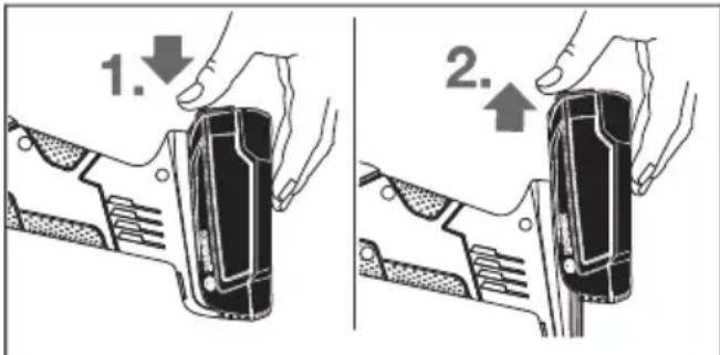
AkkymyIaTOpbl6) 6) bIfapy ywiH 6ocaty Tmecin (8)
6acblb3 xHe aKkymyIaTOpbl3 neKtp KpaJIHaH TaTpbln
blfapblHb3. Byn pette Kyu canMaHb3.
3apd deHreinHnHdkaTOpbl
3apdJeHReHHnHnKAtOpbl(5)6ipHeWecekyHJ
XapTbInaHemecToBb6acblFaHaxbipaTkblu(4) KyiHDe
aKKMyIaTOp 3apdBiHbH DeHReHH KepCeTei JxHe 3
Xacbl TycI Xapbl DnOdbHaH TypaBl.
XapbIKnOdbI Kyatbl
Y3iKc3xkapbIK 3xXacbl≥66%
Y3dkci3 kapbik 2 x kacbln 33 - 66 %
Y3dkci3 kapb1xkacbl 11-33%
aKbIpbH KblnbIbTKay 1Xacbn≤10%
AkkymyIaTOp TemnepaTypacbl-30XaHe +65^ apalbIfbIHdaftbIX Kymblc TemnepaTypacblHaH TbIC 6oNca XaHe/Hemce apTBIK KYKTeMeDen H KopraHbIC icKe Kocblnc, AkkymyIaTOp 3aprdbI DeHreinH HdNKaTOpbIHdaftbI 3XapbIK DIOAbI XbINDaM XbINbIKTaHdbI.
KopfahbIw acnantbl opHaty
AkkymyIaTOpdbI 3JKeKtp KypamMeH Ke3 KeIreH XMybIcTapdbI (MbicAlb, opHaTy, KbI3Met KepceTy, T.6.) 6actay anDbIHda, coHdai-Ak, 3JKeKtp KypaIbI tacbImaIaNay KHe caKTay Ke3iHde WbIFapblbI3.
Kockblw/ewipriuke Ke3deincoK TIO JkapaKaTTaHy KayniH TydbipaDbI.
Hyckay: Kymbic Ke3iHne Terictey Weh6epi 6y3bInca HeMece Kopfabli KaTama/3Jektp Kypal Kypblfblapbl 6y3bInca, 3Jektp Kypalblbipdien cepBnC Kb3MetHe Ki6epy Kepek, MeKeHHaNapbl «TyblHbIfa Kb3MetKOpceTy XaHe naHaNaHy KeHecTepi TapaybHaH KapaHbI3.
Tericetyre aphanfah Koprafbii KanTama
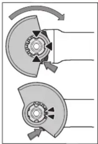
Kopfabi KaTamaHb (10)
3JekTp KypaIbIHbIH
NaTPObHa Kopfabi
KaTAmacbIHbIH KOtay
KdybpIbKaIaIapb NaTPOHa
caKeC KeIReHWe caIbIHb3.
ByfTaaydAn WbIFapy
nHTiperi (1) 6acbl
yCTaHb3.
LINHDenMoHbIHdaFbl
KOpFaWfbl KaTamaHb (10)
6acbl, KaTamaDaFbl
6yptNkTI 3JekTp KypaIbIH
ΦnaHeuHc OTbIPbI3bIHb3
XHe Kopfabi KaTamaHb
bipt etkeh db6c ectirehe 6ypbHb3.
Kopfafti KaTamaHbH (10) Kyin H Kymbc 6apbcHbH
taanaptbHa caOpHahtbHb3. By yuiH 6yraTaydbH
Wbifapy nHTiperih (1) Xofapb6acbHb3 XHe KopfAbl
KaTamaHbI (10) KaXeKyre 6ypbHb3.
KopfahbIkwantamaHbI (10) 3pdaHbIM, KynbINTAH 6ocaty nhtiperHH (1) eki Kydbipkwaacbl KopfahbIkwantamaHbIH (10) Tnicti ObykTapbHa kiperihde, petteHi3.
Koprafbii KaNTaMaHbI (10)onepaTopdbIH XaFbHa KapaYwkbIHapdbIH ywby6oMaHTbIHdaOpHaTbIHbI3.
Kopfabiw kantiama(10) 6yfaTaydaH wbiFapy nHTiperin (1)naiDanaHraHa rAha 6ypbinyi Kepek! ΘnTnece 3Jektp KypanDbI naDanaHy MyMKIn emec Xhe cepBnCTIK KbImETke Tancbipy Kepek.
Hycay: KopfAfbI KAnTaMaJaFbI KoTay KyDbipbIKaJapbl (10) TeK 3JIeKTp KypaJa KaapaTbIH Ka6DbIKbI OPhaTydbI KaMTaMacbI3 eTeJI.
TericTey uHHenH (17) XaHe 6apbIK opHaTbInaTbH KypaIapdbTa3aHaHbI3.
A6pa3nBTi Kypanbl 6ypan any XeHe 6ekity ywiH nnHdJI 6ekity TyMecin (2) 6acbn, nnHdJIbdi 6ekitih3.
- WnHdienbdi 6ekity Tymecin Tek WnHdienb ToKtaTbInfah Kynde 6acbIb3. Θntnece 3JIeKtp KypaJIbIH 3aKbIMdaybIHb3 MymKiH.
Terictey wen6epi/kecy wen6epi
AkapnafbI W KypaIapdbIH eIWeMepiH eckepiH3. CaHbIay dHaMeTpI TipeK pfnaHeuHc aNKe c6Oybl KepeK.
AanTepnepi Hemece XaIFactbIPbIu TetIKTepei naJdaJaan6aHbI3.
AnMacTbI KeckiDnCKiIepi naJaHaHFaHda anMaCTbI KeckiDnCKiIeI aHany 6aftbIbHbIH KepceTKici 3neKtp KypalbHdAfbI aHany 6aftbIbHa cHKeC 60nyBH KaDaFanaHbI3 (KOpNyctAfbI aHany 6aftbIbHbIH KepceTKici H KapaHbI3).
OpaTy peti cypTepe6ap 6eTKepeTinreH.
Akapny/kecy nckicih 6eKity yuH kblam TaTkbl comblb1 (16) 6acaacncbi3 naaHaHbHb3.
Te3 tapKbIi COMbiHdbI (16)Tek axapnay Hemece Kecy dNCKicimEn naDanahyfa 6onaBl.
By3bnmaHaH mHciz kblnam TaPTkbiu combHdbi naJdaanahbHb13 (16).
Bypan KOIOda XbIaam TapTKbiI COMbIHbIHx Ka3bIraH XaFBI (16) axapnay dncKicHe KOpceTneyihe K03 KeTki3iH; 6aftTaMa HndekctIK 6enrire Kepcety Tnic cypetin KapaHbI3.
Akapnay/KeCy DnCKicin 6eKiTy ywiH TEK KaHa KInHaKTarbl XbIJaM KbICy COMbIHbH NaIdaIaNbIHbI3 (16).
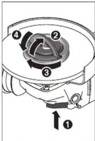
Terictey uHHdeni (2)
6ekity yuin uHHndbdi
6ekity tymecin 6acbHb3.
Xbldam TapTkblw
comblnb16)6ekity yuin
XbldAmTapKbIcCOMBI
imerih Kofapbifa Kaibpbln
XbldAmTapKbIc
combldbCaFAT TImeH
KaTbIb6paHb3.IImeKTi
XbldAmTapKbIc
combldb6ekity yuin
TeMeHre KaibpbHb3. Nsck
weiTHe tapTbIN KOIO
Xetepnikemec.
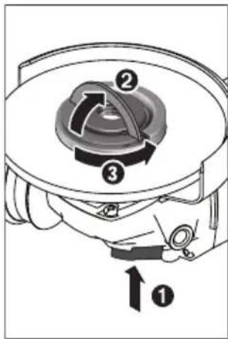
Tnict peTBe6kItinRe, 3aKbIMdAmMaFaH XbIJaAM TapTKbIu COMbIHDbI (16) KOImeH bocatyfa bola. On yuiH XblIaM TapTKbIu COMbHHbIH imMeIH Xofapbla Kaibpbl IN KblIaM TapTKbIu COMbIHdbI cafTtinHe Kapcbl KaTbI 6paHbI3. Ekaan H KaTbI 6ekmdeIreH XblIaM TapTKbIu COMbIHdbI acannneH bocatnaHbI3, eki 6yipnk Teciri 6ap COMbIH
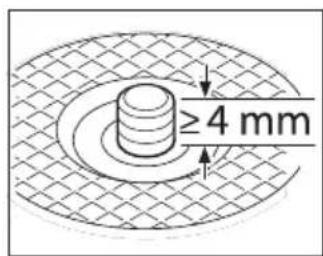
KInTiH naJaIaHaBbIb3.
KbickbiuФnaHeu neh axapay/KeCy dNcKiCih opHaTKaHHaH coH axapay uHHenIH boc 6ypaHa y3bIHbIFbl KEMHde 4 MM 6onybl Tnic. Axapay acnabHbIH KaTbI TybyHa Ke3 JeTkizhi3,
OcbIaI ON 3neKtp KpaIbIHbIH WbIFbcIHDa IINHDeIeH WbIHbN KeTneNi.
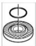
OpTaKa KeTIpeTIn 6bypTKtIN TipeK pHaHeuHne (11) nactMacca 6eIwek (JeHreNek KImacbI 6ap cakHa) 6ap. DeHreNek KImacbI 6ap cakHa Jok HeMece 3aKbIMdAnfah 6oNa, apbl Kapai naDalaHbA typbIn TipeK
fnaheuTI (11) mHneTTI Type aaybictbipy KepeK.
Terictey KypanbH opHaTkaHHa KeiH Kocy anDbIH aOpHaTydbIH AypbICTbIFbIH XaHe KypandbH epKIn aHaHaTaBbH IN Tekcepini3. Terictey Kypanbl KopraftbIe KanTaMaFa XaHe 6acka 6nweKtepre YKeMeAaHaBbIN XaTkaHbHa Ke3 XeTKi3iH3.
XennyiT api3i T erictey weh6epi
Xennyiu taipiditerictey wehbepeimen kymbictap yuin apkaan kon Koparbiubn(18) knihi3.
Pe3eHKe tericTey rapeNkeci
Pe3eHke terictey tapenkecem (19) kymbictap yuih apkaaah konkoprafblubih (18)knhi3.
Ophaty peti cypeTep 6ap 6eTTe KepcetinreH.
Pe3eHkeJeH JkacalFaH aKapnay TpeJIkeciH (19) aKapnay UHHdeIHe (17) KblJkbTbIHb3.
Akapnay DnckiciH (20) pe3eHKe axkapnay TepenkeciH (19) actbHa bacblb3.
Dohrenek CombHdbI (21) opHaTbHb3 XaHe eki 6yipnK teciri bap DeHrenek CombHdapFa apHaJIFaH KInTneH bekemdehi3.
ToctaraH Tepi3di Kblwblk/duckkinKblwblk
Toctcafah Topi3di Kblwnbikneh Xymbictap ywiH apkaaah kon KopfarfbuwbH (18) knihi3.
Ophaty peti cypetep 6ap 6eTKepeTinreH.
ToctaHaT TAp3di Kblwak/Dnckinik KbIwakTbI WnHdEnBre WnHHdeNb fnaheui WnHHdeNb npek OImacbHa TbIfbI3 TaKanbl TpyatbHdAn 6ypan 6eKiTy Kepek. AInbp TAp3di KINTneH ToCTaHaT TAp3di/Dnckinik KaIwblTb6eKemHei3.
KattbikopbirtnaTOCTaFAn TApia3i terictey weH6epi
ToctaraH Tepi3di axapnay dncicih TeK cKecti Koprafbw KanTamamEn naDanaHyfa 60aNbbl.
Kapamdb tericTre kypaib
OcbHyckaynbkTaXkoFapbdaatanetinreH6apnbK terictey KypaandpaBH naDanaHyfa 6onaBbl.
PaiJaIaHbIaTbH TericTey KypaIapbHbHpyKcatetIirHe aHaIbIMdap caHb [MnH] HeMece aHaNy XblMaMbIFbl [M/c] TMeHne6epiReH KeCTeDi I MHaepDeH ToMeH 6oImaybiKepek.
CoHbIKTaH TericTey KypaIbIbIH JxanCbIpMacbIHJa KepcetIinreH pyKcat etinreH aHaJIbIMdap CaHbIH Hemece aiHaJy KbIaNMaMbIFbIH CaKaTbI3.
| MaKC. [MM] [MM] | ||||
| D b d [MHH | -1] [M/c] | |||
| 115 | 7 | 22,2 | 11500 | 80 |
| 125 | 7 | 22,2 | 11500 | 80 |
| 115 | - | - | 11500 | 80 |
| 125 | - | - | 11500 | 80 |
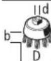
7530M141150045
UahdbjXeHe KOHkanaIapbI copy
KopfacbH 60ay, Kei6ip aafw copTapbI, MnhepaIap XaHe
metanlnap 6ap Kei6ip MaTePnAldapdbH, Wahbl
dehcayblkka 3HHdbI 60nybl MyMKIn. WaHaTIO XaHe
WahDbI Kty naDanaHyBda Hemece XaHbIHDaFbl
adamapda anleprnblk peakunnapdbI XaHe/Hemec
tbHbIC KonlnapbHbH apypnapbH Tydbipybl MyMKIn.
Keibip waH Typnepi, acipece emeH XaHe WAMuAT
araawlbH WAhbl, acipece, aaftbl eHcy KaNdbIKTapbIMeH
(xpomAt, aaftbl Kopfay 3atbl) bipre KaHeporeHep 60bn
ecenTeJIe.i Ac6ectik MaTePnAn TeK KaHa MaMaHdApMeH
eHNeyi KepeK.
-¥MbICOpHbIbIHKaKcbIKeJenTeiYiHe Ke3KeTki3iH3.
-P2 cy3ri cbiHbInbHdaFbI r3KaFapDbI naJaHaHy CbHbInaDbI.
EHeneTIN MaTePnAnDap YwH eniH3e KOJaHbIaTbH ¥fapbIMdApDbI naJaHaHbIbI3.
KymbocpHbIHdaWahHbIHXHHaHmaybiH Kaaraanh3. Hoh OHaTsyTaHybIMyMKiH.
PaindanaHy
Painanahyfa eHipy
Akkymyntopdbi ophaTy
3apraTaanFaahkMynIaTOpbl6)3neKtp KpaIbHbIH TiperHe aKKymIaTOp 6epik 6yFaTAnFaHa Kaipri3iH3.
Kocy/ewipy
3neKtp KypaBih Icke Kocy ywiH Kockbl/ewipriwi (4) aIfKaBilXbItbHb13.
Kockbiw/ewipriwi (4) opnaty wih Kockbiw/ewipriwi (4) TemeHre tipenreHwe bacbH3.
3neKtp KypanbH owipy ywiH, Kockbiw/ewipriTi (4)
Xi6epin Hemece on 6ekitiren Bonca Kockbiw/ewipriTi (4)
Kbicka aptbHaTeMeH bacIn cocbH XiepePi3.
Painanhyan andbin axapnay Kypanapbih Kaita teKcepini3. Axapnay Kypanbl 6epik opnatbnin, ew Kepeprici3 aHanybi kaxet.1 MmHyT iwiHne cbHay KymbcIn KyKtemeci3 opbHdaHb3. Akaybl 6ap, DomanaK emec XHe dipindeHn axapnay KypanapbH nainanah6aHb3. By3bIHaH axapnay Kypanapbl xapblin, 3akbIMnapra anbln Kenyi MYMKIN.
Kaeta Ko3rany caKtaBliWbl
Ke3deKoc KocbIyDaH KopFaBbI W KyaTbHaPydaH KeiH 3JIeKtp KypaIbIHbIH 6aKbIayCbI 3ICKe KocblYbIH 6oIbIPMaIbI.
KaTn aanany yin AaxbipatKbltBt (4) 0wipinre H Kyire KeTIPIN 3neKTP KypaIdbI KaTaNOCbIHbI3.
TypaKtbl 3neKtpoHnka
TypaKbI 3JIeKtpoHnKa 6oc KypicTe XHe JyKtEme KeiHne aHaIy XnIirIH TypaKbI DePNIk DeHReIe caTaNbI XHe JxMbICTbH 6ipKeNki OHMInIRIN KaMTaMcbIeTeI.
Bipkanbintbi icke kocy
3neKtpoHdbik 6ipKaIbINTbl icke Kocy KypaIbIKocy Ke3iHde aHaIy JnIirIH WekTeN, Ko3FaNTKbiWtblH KbI3MeT ety MEP3IMH y3apTaBl.
AHHany xhiinirih andbih ana taHday tetiri
Ainany xinirin andbin ana TaHay peTteriui (7) apkblkaKeTTa Hany xinirin Kymbic 6apbcihda paTeyre60ana. TeMeHderi keCTeJe cyhblnraH mHep bepiren.
| Матерnam Пайдану Альмалы-салмалы acnan PeTTey дουнгeleringen КУИ | ||
| Metall Баяды кетipersу Тарелke тэрizdiшайба | ДиSCКIMeH | 2 - 3 |
| А法师,metall Кылшakpenен сндey,ТоТы кетipersу ТocтAFан тэрizdi Кылшak,ereуКуМ КafаЗы | 3 | |
| Metall,тас Ахарлay Ахарлafыш дисk 4 - 6 | ||
| Metall Сыдьрын ожарлay Ахарлafыш дисk 6 | ||
| Metall Kecy Keckiiш дисk 6 | ||
| Tac Kecy Альмас keckiiш дисk жэne | бaftытayыш оьктар (tayЖыныстарынTek6aftытayыштaramen bіpres kecyreБолады) | 6 |
Ainany xinirirehreinepeHH6epinre MAnepi aHbIKtaMaibK MAnep 6oBnTa6bla
Kymblc Kypalbl aHaHbIMdapbIHbH yFapbIHbI caHbI 3neKtp-KypaBbIHda-KepceTINREn MAkCmAnDbI aHaHbIMdap cHaBHbA-TeH-6OnybI-KepeK. EcenTeJrRe H XbldAmdbIfbIHah TeipeK icTe TpyraH KepeK-JkapaKTap CblHybl, YWbIN KeTyI MymKH.
Painanany Hycaynapbi
Tipek Ka6bipranapda OnbikTap XacaraHda a6aHaIbI3, «Ctathka TpyaIbI HycKaynap» TapaybIH KapaHbl3.
CanmaftbyTypaKaTbI KaNbIntbI KaMTaMaCbI3 eTnece, daHdAmhbl6ekirihi3.
3neKtp KypanFa TOKtafahwa Kyykteme TycipMei3.
XorapblxkyktemeH KeHH 3neKtp KypandbH,6ipa3 cankbHdaybHa,6ipHeWe MmHyT 6oc xypicTe xymbic icteyihe MymkHdk 6epihi3.
3NeKtp KypaIbI a6pa3NBTi-KeCy cTaHnHa naIdaIaH6aHbI3.
Terictey Xehe Kecy Dnckinepihe cybifaHwa Tmehi3. UHeBepnep Kymblc Ke3iHne KblaBl.
CbIdbipbn terictey
Ewkaan Kecy weh6epnepin cbidbipin terictey yui naindaanah6aib3.
30^ - 40^ weh6ep 6ypbIbImeH cbIbIpbIn tericTey ke3iHne HkaKcbI hTnHexep anlya 6oana.3neKtp Kypanbl KaHnAn 6acBn, anfa XaHe apTKa XbIbXbITbHb3. Byn Ke3de daHdMa TbIM KaTbI KbI36aNbI, TyCIN e3reptnei JxHe apHaJap naDa 6oMaNbl.
Xennyiw Taipizi Terictey weh6epi
XennyiTupi3iTericteyweH6epimeH (Kypan)cohbiMeH 6ipre dHeec bTepjxhe npoPnIbepdi de Eneye re 6onadbl.
XennyiwTAp3diTericteyweh6epnepi aedteri terictey weh6epnepimen canbICTbipraHa y3aftpaK kbl3MeTeEDI, a3bipak Ww WbIFapabJxHe Terictey Temnepatypacbl a3bipak 6oanaBl.
Metanapdbkecy
BaiNaHbICbI a6pa3HBTeP KOMerImeH Kecy ywiH apKaaHaN Kecyre apHaJIFaH KaITamaHbI naJaHaNbIHbI3 (13).
Terictey weh6epimeh keckhe de 6ipkeki, Maepnai ywiH dypbic 6epymen xmbic icTeHi3. Kecy weh6epiHe kbicbIM TycipMeHI3, OHbEKeHTneH3 XeHe waKaMaHbi3.
Byipnk KbcimMeHaHaIHaHbIHka Kecy WeH6epiH TOKtaNaHb3.
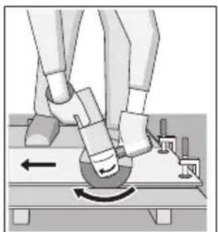
3NeKtp KypaIbI apKaaH aHaNy 6aFbItbHa Kepi Kypri3y Kepek. ΘuTnece
6aKbIaycbI3 KecinreH KepdEn WbIy Kayni TybIHaIbI.
IpofnbdepiHemece TepKbipbl Kybipnapdbk cky Ke3iHe Kecy i eHa3 KeJeHeH KImaDa 6actaHb3.
Tactbkecy(A cypetin kapaHbi3)
Tactbkeckenhe wahhbih XetkiniikTi copbinybH kAMtamacbi3 etihi3.
WahrtyKbiMackacbH KhiH3.
Byn 3neKtp Kypanbl TEK KypfKaK kcy/KypfKaTericTey yuih naDanahyra 6onaBl.
Tacbki Kecy ywiin anmac Kecy dncikineipin naJaIaNHaHKeH.
BaftaybIaTap bap KopfaraKanTaMaHbI (24) naDanaHy yuH tac waHbIH copbIn any yuH wHaCOPfbIbTI naDanaHy kepek. Bosch ocBnDaWHaCOPfbIaTApDbYcBHaBl.
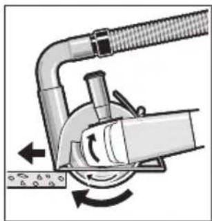
3neKtp KypaIbbl eWipHj3
XHe 6afblTayblTapdbH
anblHfbl 6nirimeh
6eWekeOpHaTbHb3.
3neKtp Kypandbi 6ipKeNki, MaTePnAnFa CaiKec 6epymen XblkbitbHb3.
KypambHda KnbipWbIKTac
eTe KEN aca KaTbl
MaTePnAnDapDbI, MbCaNbl,
6eToHbI, eHdey Ke3iHde aImac WeH6ep Kb3bIn KeTy i XHe 3aKbIMdaIybl MyMKIn. AImac WeH6epderi YWKBInap OcbHbI 6inipei.
ByJXAFdAJa JxMbICTbI TOKTaTbIHb3 XHe anMac weH6epdi 6oc xypicTe, eH XoFapbl KblnDaMdbkTa Kbicka yaKbIT BoHbI caKnBHaTbIHb3.
OhimdiikTIn aIapnbkTaT TMeHdeyi KHe YUKBiHap
anMac kecy wehbepi etnec 6onbl KanfahbH 6inipei. OHbl
a6pa3nBTi MATEpnaJa, MbCanbl, cnHKat kipniTe,
KbickaHa kecy apkbnlb tKipnyre 6oanaBl.
CtAtnKa Tpyanbl HycKaynap
TipeK Ka6bipFaIapdaFb OnbikTapFa DIN 1053 HOpMaCbHbIH 1 TapMaBfI Hemece caikec eIderi epexe KoiJaHbIaIbI. Byn HcyKaaynapdbMiHneTTI TypDe opbIHday KepeK. XyMbICTbI bactam 6ypbIH ctaTnka XeHiNderi MaMaHMeH, cayetUImeH Hemece npopabNeH keheci3.
AkkymyIopDbIOHTaINbI naHdanaHy typabI hyckaynap
AkkymyIaTopbI cyIbIKtbIKTapdaH XaHe bINFaIaH KOpFaHbI3.
AkkymyIaTOpIbI TeK -20°-50°C TemnepaTypa aykbimbHda caKaTaHbI3. AkkymyIaTOpIbI Ka3Ja KeJIKe KaIbIpMaHbI3.
AkkymyTOpdbHKeJDenTy TeciriH KymcaK, Ta3a XHe KypFak KbilwaKaNeh MyKnrt Ta3anaHbI3.
Panaanhy Mep3imHn aHTapNbIKTaN KbICkapybl
aKkymyITopdbH eckipreHn XaHe aybICTbpy KepeKTiriH
6inipei.
KokbictapblKaetaeHdeyTypanblHyckaynapblOpblHaHbI3.
TexHnKaIbIK Kytim XaHe KbI3MeT
KbI3MeT KepceTy XaHe Ta3anay
AkkymyTopbl 3neKtp KypaMaMeH Ke3 KeIReH XymbICTapbl (MbicaIb, opHaTy, KbI3MeT KepceTy, T.6.) 6actay andbIHda, cohdai-ak, 3neKtp KypaIbI TaCbIMaNDay XHe CaTAY Ke3Inde WbIrapbIHbI3. Kockblw/ewipriuke Ke3dEiCOK TIO JapaKaTTaHy KayniH TydbipaBl.
Xakcbi apicehimjxymbicictey yuih 3neKtp KypanbI MEH Xeendetkiu TecikTi Ta3a YcTaHb13.
Ka6bikapdbmyKnT CaKaTah3 XaHe KytiHj3.
Ohimepdi onapdbH caKtbyfblH kaMTamacb3 eTeiH,
EHIMdepre aTMocpepaBik KaybH-wwbHHbTHIOIHe XaHE
ackbH TEMepatypa Ke3depinH (TEMpepatpahbH Wyfbn
e3repiciin), cohbi iuiHne KYN caylenepiHn acep etyineKoI bepMeTIN dyKeHHepDe, 6eimdepe (ceKunnapda), naBnboHap MeN KnocKinepDe catyfa bonaabi.
CaTyBb (eHdpywi) catbn anyblya eHIMdep TypaBkKaKeTTi XaHe bHaBbI aKnapaTbI 6epin, eHIMdepTiTHicIHWE TaHdY MymKINdiH KAMTaMaCb3 eTyRe MiHDeTTI. OHIMdep TypaBbI aKnapaTmHdeTI TpyTe Tizimi Pecei FedepaunacbHbH 3aHHaMaCbMeH 6enrIneHreMnImeTepDi KaMTyblTnic.
ErepTybIHybI caTbI anaTbI eHIMdep aNdeKaahnaianaHbIraH HeMece OHIMepDe aKaynbIk (akaynbIKap)KoBbIHa60nca,TyTbIHybIfa 6yn Typanbl aknapat bepinyiTHic.
ΘHIMepdi caty npouecinH aacbIHda TMeHderi Kayinc3dk TaanTapbl opbHdanybl Tnic:
-CatybI CaTbI anyBbIfa YHbIMbIHbIHΦnPmaJIbIK aTaybl, opHaJnackaH Jepi (MeKeHHkaJIb) JKeHe JyMbIC peKIMI TypaJIb MAnimetTep bepyre mIndeTTi;
-Cayda 6eIMepeiHderi eHIMdepin cbiHaMaIapbI caTbn anyuBifa 6yibMdapdaftj kaz6anapMeH TaHbcYfamMkiNik 6epyi Xe H3ayaldb TeKcepicten Baca6yibMdapdbn icke KocblnybHa oKeletiH, caTbn anyuBnap 36 betIHwe opbHdaNTbH eWkaHda apekeTepre J0n 6bpMeyi Tnic;
-CatyobIOcb6yHbIMdapdbH6eNfIeHReH TaanTAPfa caikeciHHpactamacbi,ceTNHkATapdbHHeMece caikecIKXoHiHderi MmImdeMepeHHbap 6onybl TypabAknapaTbCatbHanybifa6epyreMiHdetTI;
-ⅣeHTnФнKaunBik CnnaTapbl KOK (KoTaIFaH), JapamDbInbIK Mep3imi otin KeTKeH, 6y3bNy bEnrinepi 6ap XHe NaDanaHy BoBihua HcKaynbIFbl (KITaPiacbl), MiHDeTTi CaiKeCTIK cepTnФknAteHemece CaiKeCTIK BEnrici XOK eHIMdePdi CaTyfa TbBlM cAnbHaDbI.
TytbHybifa KbI3MeT KOpCety XaHe naJaIaNHy KeHecTepi
Kb3MET Kepcety opTaBifbEhIMdi XeHDey XaHe OFAH
TEXHKnBk Kb3MET Kepcety, COHaA-Nak KocaNkbl
6enweKtep TpaBb CypaTapFa Xayan 6pepi. Kypamdaac
6enweKtep BoNbIHwa Keckin MeH KocaNbl 6enweKtep
TypaBb MAnimetTeMeHderi MeKeHHkaBbIHwa
KoJXeTImi: www.bosch-pt.com
Bosch Kbi3MeTik KeHec 6epy To6bl 6i3in ΘHimdep XHe oIapdbIH KepeK-JkapkTapbl Typalb CypaKTapblHbI3Fa JKayan 6bepei.
CypaTap KOIO XHe KocanKbI 6eIWeKTePre Tancbipbc 6epy Ke3IHne MInDeTTI TypDe eHIMHIN PhpMaNbIK TaKaTaNacBnHaFbI 10 TaH6aNbl EHM Hemipin 6epiH3.
ipyi taanTapbi MeH HopmaIapbIHbIH caKaTaybIme HneKtp KypaBH JxHDey XaHe KeinDi Kbl3MeT KepCteTy 6apblk MemKeTep ayMaFbIHda TeK "Po6eTp Boi"
nPMAblk Hemece aBTopn3aunraHaHaN Kb3MeT KepCteTy optaBlkTaBPbHdaOpbHdaIaDbE. ECKEPT! 3aHcb3XoJlmEH eKeiHReh OHIMdepdi NaJaIaNHy Kayinti, DeHCayNbIFbIHbI3Fa 3nH KeNTipy MyMkiH. OHIMdepdi 3aHcb3Kacay XaHe Tapaty Akimuiik XaHe KbIMbcTBk TApTIn 60bIHwa 3aHmeh KydanaHaDbI.
Ka3akctah
TybHybIapFaKeHec6epyKHeWaFbIMapDbI Ka6blday optanblfbl:
"Po6epT BOW" (Robert Bosch) XLIc
AJMaTbI K.
Ka3aKCTaH Pecny6nKacbl
050012
MyparbaeK.,180y
"TepeMec"50,7ka6aT
Ten.: +7 (727) 331 3100
c: + 7 (727) 2330787
E-Mail: ptka@bosch.com
CepBnctIK Kbl3MeT KOpceTy opTaIbIKTapbI MeH Ka6blIday nyHKTepiHmKeH-JaMbI TypaIbI ToIbIK XHe 03Ekl aKnapaTb Ci3: www.bosch-professional.kz pecMn caTTaHa ana anacbi3
KbI3MeT Kepcety opTaNbIKTapbIHbN 6acka da MeKeHxaiJapbIH MbiHa JepdEe KapaHbI3:
www.bosch-pt.com/serviceaddresses
3NeKtp KypanbI KeniDi naJaDanaHy Mep3imH iwiHde
EHdipyHH KecipiH eTEN WbIKKaH KaFdaJa, EHM Neci
TeMeHderi WaPITap OpbHdAnFaHaJa KeiNdk 6oBbIHwa TerIH
XeHDeyRe KyKbIbI 6oJaBi:
-MexaHnKaJIbIK 3aKbIMapDbIH JOKTbIFbl;
- naIaIaHy 60bIHHa HcKaybIK TaIaTapbIHbH 6y3bIy 6enrinepiHHKOtBIFbl;
- naJdaHny 6oHbIHwa HcCKaybIKTa caTyMbIHbIH caTy typaIb 6enriciH IN KHe caTbIN anyu bI KOntaH6acbIHbIH 6ap 6onybl;
-3neKtp KpypAlbI cepnAblk HemipHIn JxHe KeinDik TaHObHdaFbI cepnAblk HEmipDIn CaiKeCTiri;
-6iikci3xKeHey6enrinepiHHKoKtblfbl.
Keninik TEmeHderi KaFdaHapda KOnHaHbImaHbI:
-Φopc-Maxkop JaaFdaInapbIHa 6aIinaHbICTbI Ke3 KeJIreH CbIHbIKTap;
-6apIbIK 3neKtp KypaIapbIHdaFbIaIaIeKTP KypaJIbIHbIH KaIbIITbI TO3ybl.
KaIFaBbI W KOHTaKTInep, CbIMap, KblIwaKTap XeH T.6. CnKbTbI Kypan 6oJIiKTEpiH, KbI3MeT ety Mep3imH KblCKApTaBtH KaIbINTbTo3y HTHXeCiHe KeXeTTiniri TybHaFAn XeHDeY KeNlIDk aCbHa KipMeNdi:
-TaHNFTo3y(pecypctbIHToIbIKnaiJaHaHbIybl);
- KaTe opHaTy, pyKcaTcb3 MoHΦnKaUaNay, KaTe KOnlaHy, KbI3MeT KePceTy HeMece caKtay epeKeIepiH 6y3y HToTHXecIHde icTeH WbIKKaH Xa6DbIK NeH OHbIH 6eNIkTepi;
-3neKtp KypalbHa apTbIK KYkTeMe TYCKHHeH opbH aHaH akaynap. (KypaIFa apTbIK KYkTeMe TycyIH WapTCb3 6enrinepi He mbHaIap KaTaBb: Ky6bIy TyCihn naDa 6onybl Hemece 3neKtp KypalbI 6eNikTepi MeH tyINHePiH DeOpMauncbl Hemece KopblNybl, KOfarbpAtePata acepiH 3neKtp Ko3FaNTkbllbHdaFb CbIMdAp OKwayNaflbHbH KapaObl Hemece KeMipNehyi.)
TacbImanay
ByI NHTH-NOHdbk AKKMyJrTOpnap Kayinti Tayapnapfa KoIbIaTbIH TalaNTapFa caB 60nyI KepeK. PaIdaIaNHyuBi aKKMyJrTOpnapDbI KSeEe KOCbIMwa KxKaTTapCb3 TaCbIMaJIaIaIbI.
YwHwTynrHanap (MbIcAnb, aye Kcniri Hemece Xibepy) opamara JxHe MapKaIanpa KOnblaTbH apHaBt TaIaTapDbCaTay KepeK. Xibepyre DaBHday Ke3iHde Kayinti JxKyTePdITacbMaJday MaMaHbIMeH xaBapNacy KepeK.
AkkymyIaTOpIbI KOpNcbl 3aKbIMdaIHaH 6oIcaFaHa
Xi6epiH3.AuBk Tynicnepdi XeimImdeH3 XaHe
aKKymyIaTOpIbI opamada Ko3faImaTbIHdaopAh3.KaXeT
6oIca,KocbIMwa YNTbIK epexenepePi caKaTaHbI3.
Kadere kapaty

3NeKtp KypaIapDbI, aKKyMnyTopnapdbI, KepeK-KapaKaTapDbI JHe opay
MaTePnAaIapbIH 3KoIOnIyIbIK TyPbIaH DpybIC yTINImaunayFa tancbipy KepeK.
3neKtp KypanJaapdbI JxHe aKKyMnyTopnapdbI/ 6aTapeenapdbI yKoKbCbHa TaCTaMaHbI3!
TekKaHaEOeepi yuin:
Eypona 2012/19/EU epexeci 6oBbHwa xapaMcb3 3neKtp KypaIapbl JxHe Eypona 2006/66/EC epexeci 6oBbHwa 3aKbIMdaIFaH HeMece ecki akKymyIaTOp/6aTapeernap 6eNek XHHaII IN KdTe EkapatblNyI KaKeT.
AkkymyIaTOpnap/6aTapeIaNap:
JIHTHm-HoHdbik:
TacbImaJay 6eimHderi HcckaynapdbOpbHaB3 (KapaHb3,TacbImaJay",Bet213).
Româna
Instruktiuni de siguranta
Sistem electronic constant
Sistemul electronic constant mentine turatiaaprope constanta la functionarea in gol si sub sarcina, asigurand un randament uniform de lucru.
Pornire lenta
Dispositivul electronic de pornire lenta limiteza cupul motor in momentul pornirii, prelimungind astfel durata de viata utilise a motorului.
Service scule electrice
Strada Horia Macelariu Nr. 30-34, sector 1
013937 Bucuresti
www.bosch-pt.com/serviceaddresses
Transport
ITO eNKeTPOINHCTpyMeHTbT He e npEHa3HeueH, MoRaT Da IOBnWAT OnaCHOCCTTa N da IpeN3BnKaT HapaHbAHNA.
He n3non3BaIte pa60THn HNCTpyMeHTn IOnbHnTeHN npncnoc6neHn, KOtO He ca CneuaHNO npoeKTHpaHn YTBpDeHH 3a NON3BaHe OT pON3BOHNTeHa eNEKTPoHHCTpyMeHTa.ΦaKbT, Ye daJeHO npnc-noc6neHn MoKe Da 6bJe MOHTnpaHo Ha eNEKTPoHHCTpyMeHTa, He rapaHTnpa, ye pa6oTaTc Hero e 6e3onacHa.
CkopoocTaHaBbPteHeHa pa6oTHHnHnCTpyMeHT Tp8Ba Da e Hau-MaIKOTO paBHn Ha MaKcHMaHnHaTa CkopoCT Ha BbPteHe Ha eneKtpOHnCtpyMeHTN, KOnTO ce BbPTT NO-6bp30 OT IpeBnDeHOTo, MoRat Da ce pa3pyWAT N da ce pa3nETT Ha napyeta.
BbHnHnT dHaMeTpbp nDe6eHHaTa Ha pa6oTHn HnCTpyMeHT Tp8Ba Da 6bDat B rpaHnCHT,3a KOtTO eNeKTponHcTpyMeHTbTe npoeKtnpaH. Pa6oTHn HnCTpyMeHTn C HeNoDxOJaIu pa3Mepn He Morat Da 6bDat OCHypeHn N KOHTpOJIpaHn IpabINHO.
PnncbeneHHHTeHHT OTBOP c Hape3 Ha akcecoapnte Tp6Ba da nacBa ha pe36ata Ha Bana Ha brrnoaia. 3a pa60THn HHCTpyMeHTN, MOHTnpaHn Ha ceHTPOBaun Phaanu, PnncbeHNHTeHHT OTBOP Ha npncnoc6neHHeTO Tp6Ba da nacBa Ha eHTPOBaIoTO CTbnano Ha Phaneua. Pa60THn HHCTpyMeHTN, KOtO He nacBat Ha npncbeHHTEHNEIeMeHTn Ha eJekTPoHHCTpyMeHTa, Imat 6nHe, Bn6pnpat CnHIO MoT a npedn3BnKAT 3a- rby6Ha KOHTPOn Had eJekTPoHHCTpyMeHTa.
He n3no3BaIte NOBpeHn pa60THn HNCTpyMeHTn. BnHaH npEdu nO3BaHne npOBepraBeTpe 6oTHn HNCTpyMeHT, HAp. a6pa3NBn DNCKObe 3a OTyUNBaHH NnyKHaTHHH, NOJIOXKA 3a NyKHATHH NII IN3HOCBaHe, TeneHH YETKN 3a pa3XNa6eHH NIN CUYeHH TEnYeTA. Ako eNEkTPoHNCTpyMeHTbT NIN pa60THnT HNCTpyMeHT 6bDat N3NysCHaTH, rN pOBepRABeT 3a NOBpeDA INN NO3BAIte DpyrH. CNeD KATO cTe npOBepHH MOHTHpAH pa60THn HNCTpyMeHT OCTABeTe eNEkTPoHNCTpyMeHTa Da pa60TH BnpOdbJIxKeHHe Ha edHa MNHyTa C MaKcHMAnHa CKOpocT Ha BbPteHe, KaTO dbpXH-Te ce6e CN HAmHPaUe Ce Na6bIM3O NIIuA N3BbH paBHNNHATA Na BbPteHe Ha pa60THn HNCTpyMeHT. POBpeHn pa60THn HNCTpyMeHTn Ce UyIANT Ha-NecTo Ipe3 To-3N np60Hen nepNoi.
Pa6oTe c nHn npeNa3n CpeCTBa. B 3aBnCmocOT KOHKpeTHHe YcNoBn H3no3BaIte qna MacKa 3a IInue, 3aunTa Ha OUnTe Hnn PpeNa3n OUnna.Ako e Heo6xOJnMo, pa6oTe c npToHBonpaxOba MacKa, Wymo3arnywn (aHTnfoH), pbKabn u pa6oTb npectnka, KOnTo E b cbctOanHe da cnpe OTXBbpauu ManKn a6pa3NBn Napuenca. OUnTe Tpr6Ba Da ca PpeNa3eHn OT dpe6Hn napuenca, KOtTo Morat Daot XBBpUaT NO BpeMe Ha p6oTa. IpToHBonpaxOBaTa HIN DnxAteHata Macka Tpr6Ba Da MoRat Da fHNTpnpat Bb3HNKBAUN IO BpeMe Ha p6oTa npax. Ako npDblkntenHO BpeMe CTe N3IOKeHH Ha Bb3dEInCTBneTO Ha CNJeH Wym, MoKeTe Da npeTpPnTE qactNuHa 3ary6a Ha cnlyx.
ДрьхтЕ hamupaи ce ha6n30 nua ha 6e3onacho pa3ctoHne ot pa60THata 30ha. Bcekn, koIto ce ha-
MnpaBpa60HaTa3OHa,TP86BaDaHOCnIuHnPpeJa3HNcpeDCTBa.PapueHcaOTob6pabotBaHHaTeaINnn pa60THNnHCTpyMeHT MoT aOxYbpyatC roJMaCKOpocNT DaPiuHHaHapaHbAHn H3BbH HeNocepTeCTBeHaTa3OHa Ha pa6ota.
Korato n3nbHnBaTe onepaun, npn KOrTo c6uectByBa onacnoct pa6oTHnT HnCTpyMeT MoKe da 3acerHeCKpHTn NOBbpxHOCTTa pNOBOHNu NOD HAppeKeHne, OOnHpAte eNEkTPoHNcHtpMeHTa cMo DO eNEkTPoHN3npAHNTe NOBbPxHOCTHa pbKOXBaTKHe. PnKoHTaKT C pNOBOHNK NOd HappeKeHne PO MeTaHnTEyactn Ha eNEkTPoHNcHtpMeHTa MOKe da Ce nOraBn HAppeKeHne I TOBa Da npedN3BnKa TOKOB ynap.
Hnkora He octaBnIe eNktpOnHcTpymEnTa npedn BbptHeTo da e cnpno HanbNo. BbptuHr ce pa6oTeH HcTpymEn MoKe Da dOpne NobbpxHocTt N da yckopn HeKOHTpOHaHO eNktpOnHcTpymEnTa.
He BkIIOUbaIte eNEKtpoHcTpymeHTa,doKaTO ro Hocnte,obbpHaT KbM Bac.Cnyaeh DoOpnp Do BbptraunCe pa60TeH INCTpymeHT moKe da yBneue dpexnte Bu npabOTHnAT INCTpymeHT da Bu hapaHH.
IepnoHNo NOuHCTBaHTe BEHTnlaUHOHHTE OTBOPHa eNEKtpoHHcTpyMeHa. BeHTnlaTopbT Ha eNEKtpoBnRaTeIa 3acMyKBa npax, a OTnaHaTo Ha MeTaJIeN npax NO BbTpEshOcTTa Ha KopnyCa MoXe Da npedn3BnKa ONaCHOCT OT TOKOB yIap.
He pa6oTe c eneKtpoHnCtpymeHa B 6n3ocTdo IecHO3aIaHmMaTePnaH. Nckp MoarTa BaB3nA-MeHrT Te3MaTePnaH.
He H3noI3BaIte pa60THH HHCTpymeHTn npncnocO6- neHNA, KOHTo H3NCKBAT TeuHO OxnaXdaHe. IOn3BaHTo Ha BOda HIN Dpyr TeueH peaTeHT MoKe Da IpeiN3BnKa Kb-CbEHNHeHne HIN TOKOB yap.
OTkATnCBbp3HN npdeynpejxdeHNA
OTkaTe BHe3aHa peakunBa CcIeCTBHe Ha 6loKnpaHe nn 3aKnHbAHe Ha BbptTnue Ce a6pa3nBeH nCK, NOIOxKeH nCK, TeHeHa YETKa HnDpyr pa6oTeH hNCTpymeHT. 3aKnHBaHeTo Hn 6LoKnpaHeTo Npeu3BnKBA BHe3aHNO ctnpaHe Ha BbptTnue Ce pa6oTeH hNCTpymeHT, KOeTO OT CBOI CTpaHa Npeu3BnKBA HeKOHTpOInpAHO p3KO yckopraHa Ha eNEKTponHCTpymeHTa B NoCoka, 6paTHa Ha BbptHeTo Ha pa6oTHnHnCTpymeHT B TOkata Ha 6loKnpaHe.
Ako Hanp. abpa3nBeH nck Ce 3aknnn HnN 6loKnpa B DeTaNla, yacTt a OT pb6a Ha nCKa, KOrTO ce Brpa3Ba B DeTaNa, MOKe Da CE BpeKe P3KO B NOBbpxHOCTTa, BCNeDCTBHe Ha KOeTo DnckbT da OTCKOu CnHNO. NcKbT ce yckopraBa KbMa pa6oTeuH c eIeKTPoHnHCTpyMeHTa HnB O6paTHa NocOKa B 3aBnCmOcT OT TOBA B KaKbA NocOKa e DvNxHeHneTO My B ToKkTaHa 3aklnHBae. B TaKNBa CnyuAn abpa3nBHnTe NsCKOB MoRat N da ce cynT.
OkaTbB3HnKba KaTO CNECTBHe OTE HnPaBnHO nIIN IorpeuHO nON3BaHe Ha eNEKTPOHnCTpyMeHTa N MoKe da 6bJe n36eHnat Upe3 IOnXoJn INpeDnA3HN MepKn, KaKTo e ONncaHO nO-dony.
IpbkTe eNeKtpOnHcTpymeHa BnHaH 3IpaBO H noDbpxaHTe No3Nua HA TAnOTo Ha PbUeTe cN, npu KToTO ue MoKeTe eKeTHBHO da IpOTNbOCTOHTe Ha
eBeHTyaJIHo Bb3HKnHaI OTKaT. BnHaI NOJ3BaIte cnOMaTeIHHaTpaBxOKBaTKa, aKo HMa TaKaBa, 3a Da MoXeTe B MaKcHMaIIHa CTeIeH da OBlaJeEeOTKaTa HN peAKUHOHHa MOMENT pRn BKNIOUBAHe. Ako 6bDat B3eTN NOxOJaIIN PpeINa3HN MepKn, paBoTeIINrC eNEKTPOnHCTpyMeHtA MOKe Da IpoTINBOcToH Na peAKUHOHHa MOMENT HN Ha OTKaT.
Hnkora He npkTe pueTe CN B 6n30ct Do BbpTuaCe pa6oTe HnCTpyMeT MoKe da Bu HapaH.
He npbxte TnOTo CN B 30Ha, B KOrTo eNeKtpOnHCTpyMeHTbT 6bDe HxBbpNepn npEbeHTyaneH OTKaTbT 1e yckOpn eNeKtpOnHCTpyMeHTa B nocoka, o6paTHa Ha DBNXeHHeTo Ha paBoTHna HnCTpyMeHT B Toykata Ha 6nOKnpaHe.
БьдeTe N3KIOUHTeHNO BHHMaTeHn, KOraTo pa6oTHe B bTn, no ocTpH p6OBe nAp.n. N36aRBaIte p3KOTO Bp3BaHe Ha dNcKa. Brnte, ocTpHte p6OBe Hn pr3-KOTO Bp3BaHe ca npednoCTaBka 3a 3aKnHbHe Ha pa60THn INHCTpyMeHT n 3aYbHa KOHTPOJ Hn OTkT.
He moHTnpaIte pexeHa Bepn, fpe3epn Hnn DnckoBe Cbc 3b6n. TaKNBa HNCTpyMeHTn PpeH3BnKBaT YecTo OTKAT N 3aY6ba Ha KOHTpOJ.
IpeynpekdeHna 3a6e3oNaHcOCT, cneuΦnHn 3a deHocTH no uHΦoBaHe n a6pa3NBHO p3aHe
H3non3BaIte caMo dNCKOBE, npenopbUbaHn 3a Ba- uHra eneKTPoHHCTpymeHT, n pnerpaHn, npoeKTHpaHn 3a cBoTBeHTHe dNCKOBE. INCKOBE, 3a KOnTO eNEKTPoHHCTpymeHTbT He e npedHa3HaueH, He MORaT da 6bdaT oBe30NaCEHN aKeKBaTHO h Ca ONaCHN.
Pa60ThaTnOBbpXHOCTHaEKCcEHTpHKOBa6pa3HBEN dmck Tp86Ba Da e cKpTa B npeDna3HnHaKpaHHK. HenpaBnHO MOHTpAnH NsCK, KOTo ce IOnDa H3BbH npEpa3HnHaKpaHHK, He MoKe da 6bJe oBe3oNaCeH aDEKBaTHO.
IperpaDATA Tp6Ba Da 6bJe 3axBaHaTa 3dPaBO KbMeIeKTPoHnCTpyMeHTa N Da e B No3uN, OCHrpyBaMaMckmAlHa 6e3OpacHOCT, Taka Ye Bb3MOxHO HaMaIKA qAcT OT DnCKA Da e CBO6OHa KbM OepaTopa. IperpaDATA PpeIpa3Ba OepaTopa OT OKbpTBAuN ce napueHcAOT DnCKA, DoNP DO nCKA NO HeBHMaHne N OT NCKPte, KOHTo MORa Da H3ropt dpexHTe.
ДиckobeteТр6baДа ce non3BaT caMo 3a ueHnte,3a KOnto ca npedha3NaeHH. Hanpimep: He wHnfoBaH-Te c dNcK 3a p3aHe. A6pa3nBnTe nckObe 3a pr3aHe ca npedHa3NaeHH 3a OTHeMaHe Ha MaTeHnA Cpb6aHa dNcKa,CTpaHnUHO HATOBapBaHe MOKe Da rN cyuHn.
BnHaHn H3non3BaIte H3npaBHN fIaHcN, KOTo ca c nOxOJauu npOpMa n pa3Mepn 3a H36paHna DNCK. IopXoJUNTe fIaNuYKpeINBaT dNcKa n Taka HaMaJIbAT onaCHOCTTA OTCyUNBaHETo My. fIaNtTe 3a DnCKOBe 3a pR3aHe MoKe Da ca pa3NIuHn OT fIaNHTe 3a DnCKOBe 3a UInFOBaHe.
He n3noI3BaIte H3HOceHn DnCKOBe OT NO-ROEmbIrooIaIph. NsckOBete, PpeHa3NaYeHn 3a No-rolEMneKTPoIHCTpyMeHTN, He caNoXoJxu 3a No-BvCOKITE
CKOpocTN Ha BbPteHe Ha MaIKTe eNeKTpOHcTpyMeHTN MoTa Da ce pa3pyuHaT.
DonbHnTeHH yka3aHH 3a 6e3oNaChocT, cneuHnH 3a a6pa3HBHO p3aHe
H36yBaTe 6nOKpaHe Ha pexeunn HnTbpe CnHNO npntncKe. He n3nbnaBte npekaneo Dbl60Kn cpe3OBe. IpeTOBapBaHeTo Ha pekeunn DnCK yBeJIuHaBa CKIOHOCCTa My KbM h3mTaHe Hn6nKpa- He n C TOBa ONaCHOCTTa OT OTKaT Hn CuynBaHe Ha a6pa3HBnA DNCK.
He npbxt TaIOTo Ch nped HnH 3aBbptTzHc E nck. Ako npemecBaTe pekeuia NCK OT Bac hABbH, B Cnyau Ha OTKaT eKeKTPOnHCTpyMeHTbT C BbPTaHna CE DnCK MoKe Da OTCKOu HENOCpeDCTBeHO KbM Bac.
Ako pexeunrT nckCe 3aKlnnnn HnKorato npekbcBate pa6ota, n3Knoute eEnktpoHnctpymenta n ro3aPbXTe,doKaTo nckbT cnpe da Ce BbpTuHaNbIHO.Hnkora He onntBaHTe Da n3BaNTe BbpTuHcne Ce noHepuia NCKOT Cpe3a,BnpotHBen cnyau MoKe daBb3HnKHe OTkAT. OnpeJeTe H oTcPaHete npuHata3a 3aKnHHBaHTo.
He BKNIOUBAIte eNEKTPONHCTpyMeHTa, aKO ToE OeB DetaIIa. IpeIN BHNMaTeJIHO DA npOdbJXnTE pR3aHETo, H3yakaIte DNCKbT Da CE pa3BbPTN DO IIbIHNTe cn 6OpOTn. AKe eNEKTPONHCTypMeHTbT 6bDe BKIOueyen, IDOKaTO DNCKbT E CBpe3a, INCKbT MOKe Da CE 3aKInHn, Da N3CKOUY OT DeTaIIa INI Da IpeIN3BVka OTKaT.
POnnpaTe nNouHnn rOnemN DeTaun, 3a da H36erHeTe pNcKa OT npTHcKaHe Ha NcKa B MeXdHaTaNOTKAT. TOnemN DeTaHn MORaT Da ce ObHaT NOd DeHCTBHe Ha CnIaT Ha CO6CTBeHTo cT TerNo. DeTaHbT TpRbBaDa 6bDe NoDpRn OH DBeTe CTpaHn Ha cpe3a, KaKTo B 6n30ct Do cpe3a, Taka N B DaJIeHuN KpaI.
Бьдete Oc06eBOBHHMaTeHn npn Cpe3OBe c npo6HbAHe B cbIeCTByBaun CTEN Hn Dpyr 3Onn 6e3 BnHmocT OT o6paTHaTcTaHa. Brp3BaunT ce nck moKe da IpeIN3BnKa OTkAT npn IonoJaHe Ha r3o-, BOHO, eNeKtpoPBoDn Hn Dpyr o6eKn.
Cneunuyn yka3aann 3a 6e3onacnoct npn uHnfoBaHe
He n3non3BaIte IInCTOBe WkypKa C no-rotemn pa3Me-pn. PnH36opa Ha WkypKa Cna3BaIte Yka3aHnTa Ha npOn3BOInteI. Ako WkypKaTc Ce IoDaBa H3BbN IIOJIOXHH IINCK, CbIeCTByBa ONaCHocOT Pa3KbCBAHeTo N, 3axBaIaHe Ha napYeTa OT HeY IN CkBcBaHe Ha DnCKa INN OTKaT.
Cneunuynyka3aHna 3a6e3oNaChoc npn pa6oTa c TeneHH ueTKN
Cbo6pa3raBaIte ce,ue H npH HopMaIHO non3BaHe OT TeneHata Yetka OTXBbpyat Tenueta. He noJnaraTe Ha IpekomepHo HATOBapBaHe TeTHa YeTkata TeTAt MOKe IecHO da npOHKnHe Ipe3 Iekn dpexn n/nnn ppe3 KOJaTa.
Ako npa pa6oTa c TeneHa ueTka ce npenopbUba non3BaHTo Ha npedna3eh KOxUx, TeneHa TaeTka He Tp6Ba Da Donnpa npedna3HHa KOxUx. BcneCTBHe Ha cnIInTe Ha npitncKaHe nn CEHTpo6ExHnTe Cnnn DnAmEtB
pbT Ha TeIeHaTa YeTKa MoKe Ja ce yBEnuH NIO BpeMe Ha pa6Ota.
DonbHHTenHH yka3aHHa 3a6e3oNaCHOCT

Pa6oTeTc npedna3Hn ouHna.
H3non3BaIte NOxOJN np6Opn, 3a da OTKpHeTe eBeHTyaIHO cKpHTN NOJ NOBbpxHocCTTa Tpb60npoBOdH, HIN CE o6bPHeTc KbM CbOTBEHTo MeCTHO ChA6- dHTeHNO dpyKeCTBO. Bn3aHTo B cbpiNKOCHObeHne c npoBOHNIO NOHapEkeHne MOKe Da IpeDn3BnKa noJXAP NTOKOB yIap. YBpeKDaHTo Ha ra3OpnoBmOKe da DOBeDe Do EKcnNo3N. YBpeXdaHTo Ha BOOnPOBOd NpeDn3BnKBA 3HaunTEJIHH MaTePnAJIHH UeTI.
He rno dokocBaIte, npedn da ca ce oxnaHnn. Io BpeMe Ha pa6oTa DnCKOBeTe ce HarpBbAT cnHIO.
Korato 3axpaHbauoTo HnapeXeHne 6bJe npeKbcHaTo, Hanp. npn H3BaXdaHe Ha akymnaTophata 6aTePn, De6loKpaIte NycOBn npeKcbau n ro NoCTaBete B no3nue "N3KnUoyeHo". Taka npedOTbpaTBAte HeKOHTpOInpaho BO KBNouBaHe Ha enekTpOnHcTpyMeHa.
OchrybaTe 6pa6oTBaHn DaTn. TaH, 3axBaHAT C NOxOJU IN PnCnOc6JIeH Nn cKo6n, e 3acToIopeH IO 3pABO n CnYpHO, OTKoJIKOTo, aKO rDbPKeHTe CpbKa.
PnIOBpeKdaHe HnepaBnHa EKcnnoataun O T akymnatopHata 6atepna Moar Da ce otJeT npn. AkymnatopHata 6atepna Moke da Ce 3anaH nn da ekcnoopa. NorpnxTe ce 3a do6po npoBeTpaHne n npn onnKaBaanCe o6bphete Km nekap. Napte Moar Ta da pa3dpa3Hr dnxAteHnTE nbTuua.
He oTbapnTe akymyIaTOPhata 6aTePn. CbIecCTByBa ONaCHOCT OT Bb3HKnBaHe Ha KbCO CbeDInHeHne.
Akymylatopnata 6aTeprna MoKe da 6bNe NOBpeDeHa OT OCTpn npeMeTH, HAp. NpOHN nn OTBeptKn, HN ot cnHn ydapn. MoKe da 6bDe npedn3BnKaHO BbTpeW-Ho Kbco cBeDHeHne n Akymylatopnata 6aTeprna MoKe da ce 3aapan, Da 3anyu, Da ekCnNoHa pa Hn da ce nper-pee.
H3non3BaIte akymylaTophata 6aTePnca Mo B npOdykTH Ha npOn3BODHTeN. CaMo TaKa TRe e npedna3eHa OT ONaCHO 3a He NpeToBapBaHe.

IpeJa3BaIte akymyIaTOPHATA 6aTePnI OTHBCOKN TeMnePaTyPi, HAp. BcNeIcTBHe Ha npOdbJnxITEnHO n3NaIarHe Ha IInpeKTHACbHueBA CBeTINHa, ObH, MpbCOTn, BOda NOBJXHBAHe. IMa ONaCHOC T EKCnIO3nIKbCO CbeDInHeHne.
OnncahneHa npoduktaNdeHocCTTa

Ipooyete BHNMaTeHOB BCnKu yKa3aHn HnHCTpyKcHn 3a 6e3onacHOCT. IpnOyckn npn Cna3BaHTo Ha nHCTpyKcHnTe 3a 6e3o-nacHOCT u yKa3aHnTa 3a paBota MoRat da
HMaT 3a NocJeDCTBHe TOKOB yIap, IoxAp H/ HIN TeKKn TpaBMN.
MOnI,IMaTe ppeBnI n3o6paKeHnra T B npEHaTa yacT ha pbKOBOdCTBOTO 3a pa60Ta.
PpeHa3NaueHne Ha eNeKtpoHcTpymeHt
EneKtpOnHCTpyMeHTe npedHa3Haueh 3a p3aHe, IuNΦoBaHe, rpy6o IuNΦoBaHe n NocnCTBaHe C TeIeHa YeTeKa Ha MetaIIH NOBbpxHOCTn 6e3 NoI3BaHe Ha BOda.
Pn pr3aHe c KOMno3HTH dNcKOBe 3a pr3aHe Tpr6Ba Da ce nIPOJ3Ba CneuHaEn PpeJa3eH KOxUx 3a pr3aHe.
Pn p3aHe Ha KameHn MaTepnaHn Tp6Ba Da 6bJe OcnrypeHa DoCTaTbUHO MoUHa acnnpauOnHn CnCTema.
CytBbpeHn OT npOH3BOJNTeIpa6OHTN HNCTpyMeHTn eJeKTPoHnCTpyMeHTbT MoKe Da ce N3PON3Ba 3a WnΦoBaHe c WKypKa.
H306pa3eHH enemeHTN
HomepupaHTo Ha eIeMeHTte Ha eIeKtpOHCTpyMeHTa ce OTHacdo H3O6paXeHHa HA cTpaHnUte CfHypTe.
(1) Ocbo6oxdaaunoc3a npedna3HnKoKyx
(2) Bytoh 3a 3actonopraBaHe Ha nnHnDeta
(3) Ctpenika Bbpxy Kopnyca 3a nocokata Ha BbpTeHe
(4) NyckoB npekcbau
(5) INHnKaTOp 3a cTeNeHTa Ha 3apeJeHocT Ha aKymnaTopHaTata6aTePnA
(6) AkymynaTopHa 6aTepeHra a)
(7) IopoCTTHa BbPTeHe
(8) Bytoh 3a OTKIIIOUbaHe Ha akymlyaTopHaTa 6aTepeHna
(9) CnomaRaTeHa pbKoXBaTKa (H3OJIpaHH NOBbpxHOCTN 3a 3axBaUaHe)
(10)Пре徳пазен кожух зашлфован.
(11) PtoMaaФlaHeuC O-tpbCTeH
(12)ДиСКЗaшпфОВанe
(13)Претпаэн кокух за рязанe
(14)ДиСКЗа ряЗанe ^a)
(15) YauKOBuDcHnCKOTTBpMDaTna
(16)Бbp3006TЯЖHa raiKa cbc ckO6a
(17) Ban
(18) 3aunita 3a pbutea
(19)Гумен положенДиСкa)
(20) Lkypka
(21) Kpbrrna raika
(22) YauKOBuHa TeHeHa YeTkaa
(23) PbkoXBaTka (H3OlnpaHn NOBbpxHOCTn)
(24) PpaxOn3cmyKBaU KoxyX 3a p83aHe C BoJeua Wei-Ha a)
3apeKdaHe Ha akymylaTopHaTa 6aTepeH
H3noJ3BaIe cAmo nocOueHIne B pa3dena TexnuecKn daHHN 3apAHN yCTpoiCtBA. CAmo Te3n 3apAHN yCTpoiCTBa ca npDxOJaUN 3a H3noJ3BaHaT a BB Baunie eNeKTPoIHhCTpyMeHT IHTHeBO-IOHHa aKyMyNaTopHa 6aTePnIa.
Yka3aHHe: AkymlyaTopHaTa 6aTePnCe doCTaB yacTNo 3apeDeHa. 3a Da IOCTnHTe pblHnKaNaUTeT Ha akymlyaTopHaTa 6aTePn, npei PbBOTO n3noJ3BaHe r 3apeTe DOKpaB V 3apdHToO yCTpoIcTBO.
HNTeBO-NOHaT aKymaTOpHa 6aTePnMoKe Da 6bDe 3apeJdHa No BcKaO BpeMe, 6e3 ToBa Da cBkPaUaBA DblrTo paHocTt N. IpeKbcBaHe Ha 3apeXdaHeTo CbIoo He N BpeDn.
ПиTNHeBO-инHaTаakymaTOpHa 6aTePnE e3auntHe cpeuDbIb6Oko pa3peKdAne ype3 eNeKTpoHHaTa CnCTeMa "Electronic Cell Protection (ECP)".Пи pa3peKdAne Ha akyMylaToPHaTa 6aTePnE eNeKTPOHnCtpyMeHTb Ce n3KJIIOUyBa OT ppeJna3eH npeKbcBau:Pa6oTHnTnHcTpyMeHT cInpa da ce DBNKn.
CneabTomauHTo H3KIOUbaHe Ha eNEKTPOHHCTpyMeHTa He npOdbJXabaTe Da HATNcKaTe NyCKOBn npekcbau. AkymnatopHaTa 6atepna MoKe da 6bne NobpeedeHa.
CnazBaIte yka3aHnra 3a 6paKyBaHe.
I3BaXdane Ha akymylatopHaTa 6aTepeH

3a n3BaJdaHe Ha aKymyIaTopHaTa 6aTepeHn (6) HATNCHeTc 6yToHa 3a ocBo6OxJaBaHe (8) n3DbpNaTe aKymyIaTopHaTa 6aTepeHn OT eNeKTponHCTpyMeHTa. Pn ToBa He npna-raIte cHna.
HdNkaTop 3a cTeNeHTa Ha 3apeDeHoCT Ha akymynaTopHaTa 6aTepnA
CBeTINHHNAT INHnKaTOP 3aapeKdahe Ha akyMnyaToppa (5), CbCTOaIc ot 3 3eJeHN CBeToAnoJa, NOKa3Ba 3a HAKoKo CeKyHn CbCToHnEto Ha 3apeHeocT Ha akyMnyaTopHaTa 6Bepn, KORATO NysCKOBnT npeKbcBauch (4) 6bJe HaTHCHat HanoIOBnHa nn DOKpaI.
CbeToaNoKanaunTeT
HenpeKbchaTo CBeTeHe 3x3eNeHo ≥ 66%
HenpeKbchaTo CBeTeHe 2X3eJeHo 33-66%
HenpeKbchaTo CBeTeHe 1x3eJeHo 11-33%
BaBHO MURHe 1 x3eNeHo ≤ 10%
Tpnte cBeToNDnOda Ha HnDnKAtopa 3a akymyNaTOpHaTa 6aTepeHn Mrrat 6bp3o, aKO temnepaTypaHa na akymyNa-TopHnTe 6aTeepn E n3BbH pa60THn Tempepaten HnTePbaN or -30 do +65 C n/nn ce e 3aJeCTbana 3aun-tata cpeuy npetOBapBaHe.
MOnTnpaHe Ha 3aunTHo cbOpbXeHne
IpeHn da H3BbPwBaTe KaKBtO n Da e DeHocTH no eNeKtpoHHCTpyMeHTa (HaNP. TexHuecko 06cnyXbaHe, CmHa Ha pa6oTHn HHCTpyMeHT n T. H.), KOrato ro TpaHCnOpTnPaTe Hn CBxpaHBAte, DeMOHTnpaTe akymnatopnata 6aTeprna. CbueCTByBa ONaCHOCT OT Ha paHBAhe npn 3aJeHCTBaHe Ha NyCKOBn IpeKbCBAu No HeBHMaHne.
Yka3aHHe: Cnei cuynBaHe Ha a6pa3nBcN IO BpeMe Ha pa60Ta Hn npn NOBpeXdaHe Ha npncOco6NeHnraTa 3a 3ax
Baúhahe Ha eIeKtpoHcTpymHe Ta Hn Ha IpeJa3Hn KOKyX eIeKtpoHcTpymHeTbT Tp8Ba Da 6bJe N3PpaTeH 3a peMOHT B OToPn3HpaH cepBn3 3a eIeKtpoHcTpymHeTH, 3a aDpeCn Bx. pa3dEel "KlneHTcKa cIyX6a N KOHCytTaunr OTHOCHO yNoTpe6ata".
PpeNa3eKoKx3aWlnfoBaHe
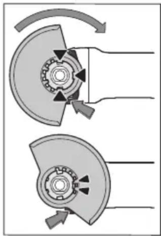
NocTaBeTne npedna3HnKoJyX (10)Ha 3axBa7aUToCTbNaIHO Ha eNeKTponHCTpyMeHTa Taka,Ye KOnIPAuHTeBp6uIN Da cBbNAdHATc KaHaJIte Ha CTbNaITo. PnTOBa HAtncHETe N 3aDpBXKeOCBO6OxJaBaUHraNoCT (1).PnTncHETe npedna3HnKoJyX (10)KbM ShnKaTaHa eNeKTponHCTpyMeHTa,doKaTo bOpTa Ha npedna3HnKOJyX DoIpe Do fPaHeca Ha eNeKTponHCTpyMeHTa 3aBbPtTe npedna3HnKOJyX,
IOKaTo UyeTe OTueTnIBO NpeupaKBaHe.
PerynpaTeNo3uTHaNapeDna3HnKoKyx(10)cbo6-pa3Ho KOHKpeTHte pa6OTHn ycNobn.3a ceNTa HATNCheTeOCBO6oxdAbaunnoCT(1)Harope n 3aBbpteTe npedna3HnKoKyx(10)BKeNaHataNo3uTn.
BHHaHn HAcTpoBaHte npedna3HnKoKyx (10) taka, ue nDbete Tbp6nHa oCBO6OxJaBaunn loct (1) da Bn3at B npedbHeHte 3a ceNTa OTBOPn Ha npedna3HnKoKyx (10).
HactpoTe npedna3nna KoxyX (10) taka, ye da ce npedotbpaTBA nTeHeTo Ha Nckpn no nocoka Ha onpeatopa.
PpeJn3HnT KoxyX (10) Tp86Ba Da moKe Ja ce 3aBbPra cAmo Korato ocbo6oxJaBaunr NoCt (1) eHaTHcHAT! B npOTHBen Cnyaue neKtpOnHCTpyMeHTbT He6NBa B HnKaBb Cnyaua Da 6bJe NOn3BaH n Tp86Ba Da6bJe H3npaTeH B cepBn3 3a peMOHT.
Yka3aHHe:KoInpaIHTe TbP6nH Na npEJa3HnKoKxu (10) rapaHTpA,ye Ha eNkTPOHCTpyMeHt a MoTa Da 6bDaTMOHTIpaHn cMo NODXOJU INpeJa3Hn Koxycn.
PpeIpa3eH Koxy 3a p3aHe
H3non3BaIe npn pR3aHe cbc Cbbp3aHa Wkypka BnHa-rn npedna3HHKoKyx 3a pR3aHe (13).
Pn pr3ahe B kambk BnHa rOcHpyraBaiTe docTaB4HO MoHa acnnpauOnHb CnCTema.
IpePnA3HnT KoxyX 3a pR3aHe (13) ce MoHTnpa KaTo npEpaNa3HnKoKxY 3a UnOBaHe (10).
Ppaxon3cMyKbau KoKyx 3a pR3aHe C BOeua WeHa
IpaXOn3cMyKBaunrT KoxyX 3a pR3aHe C Boeua WeHa (24) ce MoHTnpa KaTo IpeJa3HnRA KoxyX 3a WnloBoaHe (10).
CnomarateenHa pbkoxBaTka
H3non3BaIte Baunna eNektpoHHCTpymeTc mO c MoTHnPaHa cnomaraTeHa pbKoXbTaKa (9).
3aBnHTe cNoMaTaTeHaTa pbKoXBaTKa (9) B 3aBncMOCT OT NaHHa Ha pa6Ota BdCHO nn BnBO Ha peDyKTopHaTa rnaBa.
Bb6ponornbuaa cnoMaratenna pbkoxBatka
Vibration
3aBnHTe cNoMaTeHaTa pBkoXBaTKa (9) B 3aBncnMocT OT HaNuHa Ha pa60Ta BnCHO Wn BnBO Ha pe
DyKTOpHaTaTnBa.
Bn6pOorIbIaIaTa cNOMaIaTeJIHa pbKoXBaTKa HaMaIyBa npedabAHHe Na pbKaTa Bn6paun N ocHpyRaNo-JeKa n no-cnrypha paOta.
B HnKaBb CnyaH He ce OnHTBaHTe Da n3MeHrTe cnoMaratEnHaTApbKOXBAtKa No KaKbBTo N da 6HNo Ha-HH.
He n3noJ3BaIte cnoMarateHaTa pbKoXBaTKa, aKO e nobpeDeHa.
3aunta 3a pbue
MoHTHpaTe 3a pa6oTa c rymeH noDIOxKe HnCK (19) HnC yawKOBnHa TeHeHa YETKa/DnCKOBA YETKa/BetPhNo06pa3eH nactHHaT dNcBnHaHn 3aunntata 3a pbue (18).
3aKpeTe 3aunTaTa 3a pbue (18)cbc cnoMaTepHa pbkoXBaTKa (9).
MOnTnpaHe Ha ⅢnHΦoBaunHnHCTpyMeHT
Ппени КЗврша Te KAKBTO I Da e DeHocTH NO eNeKtpOnHCTpyMeHTa (Hanp. TexHnuecko 06cnyXBa- He, CMHa Ha pa6OTHN HnCTpyMeHT N T.H.), KOrato ro TpaHCnOpTnPaTe Hn CbXpaHnBAte, DemoHTnpaTe akymyNatopHata 6aTeprna. CbIeCTByBa ONaCHocT OT Ha paHnBaHe np3aJeHCTBaHe Ha NycKOBn IpeKbcBaU No HeBHnMaHne.
He ndoKocBaIte, npedna ca ce oxlaHnn. IIO BpeMe Ha pa6ota dNCKOBeTe ce HapRBAt CnHO.
ПоунстeteВанa(17)ИВСИКINДЕТайи,КОТTOИЕMOHTIPA-Te.
Pn3aTgAHe n ocB6oxJaBaHe Ha HNCTpyMeHTte 3a uHnΦoBaHe hATncHe 6yToHa 3a 6nOKpaHe Ha Bana (2), 3a da3aBpKInTe Bala HeNoDBrKeH.
HaTnCKaIe 6yToHa 3a 6nOKHpae Ha Bana cAmo KoraTo To e B nokoi. B npotnbEN cnuyaen eEnktpOnHCTpyMeHTbT MoKe da 6bNe noBpeDeH.
Dnck3a wlnfoBahe/pra3ane
BHHMaBaIte 3a pa3MePHTe Ha HNCTpyMeHTte 3a IINΦOBAHe.ДиAmEtbpbT Ha OTbopa Tp8Ba Da e NOxOJaU 3a NoemaJnA ΦIaHeu. He n3NoI3BaIte aIaITePN Hn PeDyIpaU 3BeHa.
Pn no3BaHTo Ha dHaMaHTeHn peKeuN DnCKOBe BHMaBaTe cTpeKATA 3a NocOKaTa Ha BbptHe Ha DNcKa Da CbBnaDa C nocOKaTa Ha BbPTHe Ha eNEKTPOINHCTpyMeHTa (BHXTe cTpeKATA 3a NocOKaTa Ha BbPTHe Bbpxy Kopnyca).
IocneIOBaTeHOCTTa Ha MOHTaK e BnIMa Bbpxy rpaHuaTa CTpaHua.
3a 3akpenBaHe Ha IINΦOBbUHnI DnCK/DnCKa 3a pR3aHe H3- nON3BaTe 6bp3006TJxHa rAka (16) 6e3 npyHn HnCTpyMeHn.
Бьрзобгхнота raиka (16) може д ce n3no3Ba ca-mo 3a wlnfoBbUHn HnpeXeun DnCKOBe.
H3no3BaTe caMo 6bp3oo6TjXHa raKa B 6e3yKOpHo cbCToHHe (16).
BHHMaaTe npn 3aBHTBaHeTo 3a TOBa,HaIINcaHaTa ctpaHa Ha 6bp3oo6TjXHata raKa (16) da He couN KbM dNcKa.
3a 3akpenBaHe Ha shnfoBbHn DnCKOBe / DnCKOBe 3a p3aHe H3noJ3BaIte CaMo BkIOueHaTBA OKOMnNeKToBkata 6bp30o6TjXHa raKa (16).
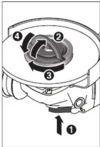
HaTnchTe 6yToHa 3a fHKcnpaHe Ha Bala (2), 3a dafHKcnpate Bala 3a WnfoBahe. 3a Da 3aterHete 6bp30o6TjXhata rAka (16),BnHrTe cKo6ata Ha 6bp30o6TjXhata rAka N 3aBbpte CnH0 6bp30o6TJXhataa rAka N O YacOBnka.CBaIe TCKo6ata 3afHKcnpaHe Ha 6bp30o6TJXhata rAka.3atraheNo pb6a Ha Dncka He e DOCTaTb4Ho.
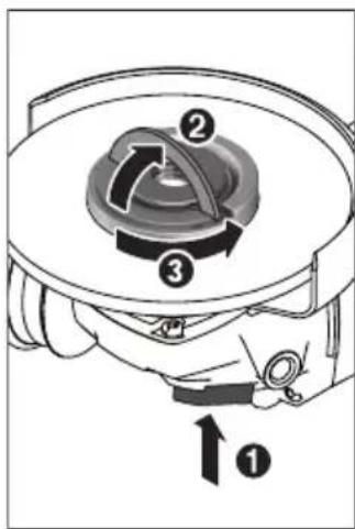
IpaBnH0 3aTeHata n HeNoBpeDeHa 6bp3oo6TJHK Ha raiKa (16) MoKe da ce pa3Bne Ha pbKa. 3a cenTa NOBnHHe TcKo6aHa 6bp3oo6TJHKHATA Raika n CInHO 3aBbPTe 6bp3oo6TJHKHATA Raika O6paTHO Ha yacOBnKa. B HnKaKb CnyaH He ONHTBaHTe Da pa3BNBaTe C NHCtpyMeHT, 3a cenTa H3NoJI3BaHTe KIOUc DBA OTBopa.
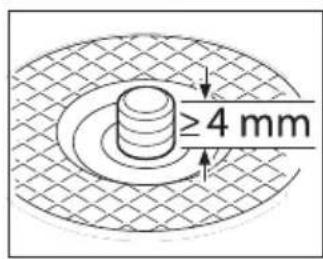
Cne MoHTnpaHTo Ha ueHTpoBaunn FnaHeu N Dncka3a WnfoBaH/ Pra3aHeBbJINHaTa H CBO6OHaTape36a Ha Bala Tp86Ba da6bHe Hau-Manko 4 MM.
BHMaBaTe pa6oTHnHr HnCTpyMeHT 3a WnHpObaHe Da
e 3axBaHaT IO6pe, 3a Da He Ce OTdenn OT Bana No Bpeme Ha BbptHe.
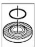
OkoNcTbnaIOTa pa6oTHnHnCTpyMeHT Ha ueHTPOBaunuФnaHeu (11)e nocTaBeH npbcTeH OTn3KycCTBeH MaTePnA (O-tpbCTeH).Ako O-npbcTeHbTnnncBa Hn e NobpeH, npeHn Da non3BaTe ueHTPOBaunuФnaHeu (11)
Tp6Ba 3aBnKHTenHO da NoCTaBtHe HO B-tpcTeH.
Cne MoTHnpaHTo Ha a6pa3NBnHa Dnck, npEn Da BKNIOHTe eNEKTPoHHCTpyMeHTa, ce yBepTe, ye nC-KbTe MOHTpAn PpaBnHO M0Ke Da ce BbpTN CBO-6ONo. YBepTe ce, ye a6pa3NBnT Dnck He DoNpHa do npEpa3HH KoxyHnn DpyrH DeTaHn Ha eNEKTPoHHCTpyMeHTa.
Betpnoo6pa3eH nlaactnHcT dNck
MOnTnpaTe 3a pa60TH C BepnNoo6pa3eH nnaCTHHaT DnCK BnHar 3auNTata 3a pbue (18).
Tymennojnoxekn
MoHTnpaTe 3a pa6oTH C rymeHn IOIOJKeH nck (19) BnHaH 3aunrTa 3a pbue (18).
IocneIOBaTeHocTtHa MoHTaK e BnIma Bbpxy rpaHuaTa CTpaHua.
N36yTaIe TymEnH NIOJIOKeH DnCK (19) Bbpxy IINHdena 3a WnHDoBaHe (17).
aawkoBnHa TeeneHa YetKa/tnckoBa YetKa
MOnTnpaTe 3a pa6oTH c yaWkoBnHnata TeIeHa YeTKa HnDnCKOBaTa YeTKa BnHarn 3aunrTaTa 3a pbue (18).
IocneIOBaTeHOCCTTa Ha MOHTaK e BnIMMa Bbpxy rpaHHaTa CTpaHua.
UaIKOBnHaTate TeneHa YeTKa/DnCKOBaTa YeTKa Tp8Ba Da MoKe Da ce 3aBnHTBa DToTOKoBA Bbpxu Bana,Ye da ce KcHcnpa B Kpa Ha pe3bata Ha Bana Bbpxy FnaHeca Ha Bana.3aTerHeTe UaIKOBnHaTae TeneHa YeTKa/DnCKOBaTa YeTKa C BnKOB KJIou.
Tbbpocnbaencauskobndenck
Pon3BaHeTo Ha qaIKOBnDeH dNcK ce DOnycka cAmO B KOM6HaCnI C nOxOJaI npEJa3eH KOxy.
Pa3peweHHNCTpyMeHTn 3a WnHΦoBaHe
MoxTe Da H3No3BaTe BCNU NOCOueHn B HAcToaTO pkoBOCTBO 3a EKcNIOaTaun HNCTpyMeHTn 3a WNIΦoBAHe. OnyctHMnte o6opOn [min] pecn. neppephHa ckOpocHa [m/s] Ha H3No3BaHNte HNCTpyMeHTn 3a WNIΦoBAHe Tp86Ba Da OTROBAPAT Ha-MaNKo Ha DaHHNTe OT DOHATA TabNuca. ETo 3aIo Cna3BaIte ONYCTHMnte o6opOn, pecn. nepHepHa ckOpocHa etNKeTa Ha INCTpyMeHTa 3a WNIΦoBAHe.
| makc. [mm] [mm] | ||||
| D bd [min] | -1] [m/s] | |||
| b | 115 | 7 | 22,2 | 11500 80 |
| 125 | 7 | 22,2 | 11500 80 | |
| D | 115 | - | - | 11500 80 |
| 125 | - | - | 11500 80 | |
mKc.[mm][mm]


Dbdmin
^-1 [m/s]
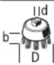
7530M141150045
CnCTema 3a npaxoynahe
PpaxOBe,OTdEJIaNc npn 6pa6oTbAHeTo Ha MaTePnaHn KaTO CbIbPkaU OIOBO 60H, HAKOH BIDObe IbpBecHa, MHEpaHn MeTaN MoT Da 6bDaT OApCN 3a 3dpaBeto. KOHTbT DO KOKaTa HIN BDNWBAHeTo Ha TaKINBa PpaxOBe MoT Da IpeDn3BnKaT aIeprHuN peakuH N/nn 3a6oJbAHn Ha dNXaTeHNHe TbTHNaHa pa6oTeuN c eJeKTPOHCTpyMeHt Hn HAmpaUcN c Ha6n3O nua.
OnpeeneHnpaxObe,Hanp.OTdienaHTe ce npn o6pa6oBaHe Ha 6yK nDb6,ce cunTat 3a KaHcepoReHHN,OCo6eHO B KOMbHaCnC XHMKnAaH 3a TpeHpaHe Ha DbpBecnHa (xpoMaT,KOHCEpBaHTnIdp.).Donycka ce o6pa6oTBaHTo Ha cbDbPkaa a36eCT MaTePnaHn CaMo OT CbOTBeTHO ObyeHN KBaHnΦnUpaHn Nua.
- OcnrypBaIe Iobpo npoBepraBaHe Ha pa60THOTo MCTO.
-Прелорьа ce Изпольва HeTo Ha ДИХаTeнHa Мacka cФиNTbp OТ Клac P2.
Cna3BaIte BaIIHnIte BbB BaIaTcTpaHa 3aKoHOBn pa3nope6n, BaIIHn npn o6pa6oTbaHe Ha cBoTBeTHnte MaTePnaJIH.
H36yBaTe HATpynBaHe Ha npax Ha pa60THOTo MCTO. PpaXbT MoKe IeCHO Da ce CaMOBb3PnaMeHn.
Pabota c eleektpoHHcTpymenta
Nyskahe BekcnnoaTaH
NoctabnHe Ha akymyataophata 6aTepeH
BkapaTe 3apeHeHaTa akymyIaTopHa 6atepeHn (6) B KpaKa Ha eNeKtpOnHcTpymeHtA,doKaTo 6bJe 3axBaHaTa 3dpaBO.
BknIOUbaHe n H3KIOUbaHe
3a BKNIOUBAHe Ha eIeKTPoINHCTpyMeHTa npEmecTe Te NycKOBnI PpeKbCBaY (4) HAnpe.
3a 3actonopbahe Ha nycOBn IpeKbCBaue (4) HATNCHeTe nycOBn IpeKbCBaue (4) B IpeHnMy Kpa,doKaTo yceTHe IpeuPaKBaHe.
3a n3KIOUbaHe Ha eIeKTPoINHCTpyMeHTa OTnycheTe nyCKOBn IpeKBcBaU (4) pecn. aKO e 3acToOpEn, KpaTKOBpeMeHH OHaTHCHETe NOTycheTe NyCKOBn IpeKBcbu (4).
PpeH non3BaHe npOBepaBaiTe uHnΦOBAuNTe HNCTpymeHTn. UHnΦOBAuNT HNCTpymeHT TpaE MOHTnpaH 6e3yKOpHo N da MoXe Ja Ce Bbptn CBO6oHNo. OcTabaIte 3a npo6a HNCTpymeHTa Da ce Bbptn B npoJbLnXeHne Ha NaMko 1 MmHyTa. He n3non3BaIte NOBpeHn, 6Neu nn Bn6pnpauu uHnΦOBAuH NHCPTpymeHTn. POBpeHn UHnΦOBAuH NHCPTpymeHTM Morat Da ce pa3pyaT n Da npen3Bkata HapaHaBaHna.
3aunita cpeuy nobtopHO BKIOUbaHe
3aunitata cpeuy NOBtropHO BKIOUbaHe npedotbpaTBA HeKOHTpOINpaHOT BKNIOUbaHe Ha eNEKtpOnHCTpyMeHTa CneI pKeBcBAHe Ha 3axpaHbAHeTo.
3aДаВКЛIOHTE OTHOBEOENEKTPOINHCTpyMeHTa NOCTaBeTe nycOBnI ppeBknIOUbaTeI (4) B N3KIOUeHa N03NcIry NOTHOBO BKIOUte eNEKTPoINHCTpyMeHTa.
MóyI 3a noctoHHa ckopoCT Ha BbptHe
EneKtpoHEn Moyn PndbPka CkopocTHa H BpTeHe Ha npa3eH XoN IIOH HatoBapBaHepaKTnueckn NocToHHa, c KOeTO OcnIpyBa NoCTOHHoD6pa pOnn3BOJNTenHOCT.
Плавно BКЛIOчBAнe
EneKtpoHNo ynpaBHeHne 3a PnabHo BKIOUbaHe orpaHuaBa BbPTaMOMeHT npi CTapTnpaHne HyBeJIuHaBA DblrToPaH-HocTtHa eNEKtpoDbIrTaTeIa.
PpeBapnteneH36OpHaCKopoCtTaHa BbptHe
C KOnelueTo 3a perynipaHe 3a npedBapnteHn3bOp Ha obopOTte (7) MoKTe Da n3MeHrTe cKOpocTtHa BbpTeHe cbOpa3Ho KOHKpeTHata DeHOCCTcbIoo Hn PO Bpeme Ha paBoTa. CToHocHTe B Ta6nucata No-dony ca npenOpbUHTeHH.
MaTePnAn PpInIOxKeHne Pa6oTeH HnCTpyMeNT IOn3uHa Na NoteHcNoMeTbpa
| Метал П Dempавае на Six Six Six Six Six Six Six Six Six Six Six Six Six Six Six Six Six Six Six Six Six Six Six Six Six Six Six Six Six Six Six Six Six Six Six Six Six Six Six Six Six Six Six Six Six Six Six Six Six Six Six Six Six Six Six Six Six Six Six Six Six Six Six Six Six Six Six Six Six Six Six Six Six Six Six Six Six Six Six Six Six Six Six Six Six Six Six Six Six Six Six Six Six Six Six Six Six Six Six Six六大 Six六大六大六大六大六大六大六大六大六大六大六大六大六大六大六大六大六大六大六大六大六大六大六大六大六大六大六大六大六大六大六大六大六大六大六大六大六大六大六大六大六大六大六大六大六大六大六大六大六大六大六大六大六大六大六大六大六大六大六大六大六大六大六大六大六大六大六大六大六大六大六大六大六大六大六大六大六大六大六大六大六大六大六大六大六大六大六大六大六大六大六大六大六大六大六大六大六大六大六大六大八大八大八大八大八大八大八大八大八大八大八大八大八大八大八大八大八大八大八大八大八大八大八大八大八大八大八大八大八大八大八大八大八大八大八大八大八大八大八大八大八大八大八大八大八大八大八大八大八大八大八大八大八大八大八大八大八大八大八大八大八大八大八大八大八大八大八大八大八大八大八大八大八大八大八大八大八大八大八大八大八大八大八大八大八大八大八大八大八大八大八大八大八大八大八大八大八大八大八大八大八八八八八八八八八八八八八八八八八八八八八八八八八八八八八八八八八八八八八八八八八八八八八八八八八八八八八八八八八八八八八八八八八八八八八八八八八八八八八八八八八八八八八八八八八八八八八八八八八八八八六六六六六六六六六六六六六六六六六六六六六六六六六六六六六六六六六六六六六六六六六六六六六六六六六六六六六六六六六六六六六六六六六六六六六六六六六六六六六六六六六六六六六六六六六六六六六六六六六六六六6666666666666666666666666666666666666666666666666666666666666666666666666666666666666666666666666666 Буров, Метал | Почиствае с чека, пөрмава- He Na рьжда | Чашковеда телега чека, Shкчрka | 3 |
| Метал, каменни Maернай | Шлфован | ДиSC 3a Шлфован | 4-6 |
| Метал Губошлфован | ДиSC 3a Шлфован | 6 | |
| Метал Рязанe | ДиSC 3a рязанe | 6 | |
| Камын | Рязанe | ДиMaHTeн дIscN и Наразв liaВа- Shea SheiHa (ДОпUCSа ce ряЗанeto Na KMENHи Maернai n da ce ИЗ- BыршВа сamo c Hаразв liaВацha SheiHa) | 6 |
IocouenHe cToHocTn Ha CTeNeHTa Ha CKOpocTtHa BbPteHe caOpneHTnpoBbUHN.
CkopoctTHa BbptHe Ha pa60THHn HnCTpyMeHT Tp8Ba Da e Ha-MaNKOTO paBHa HA MaKCHMaHnHaTa CkopoCt Ha BbptHe Ha eneKtpoHHCTpyMeHTn, KOHTO Ce BBPTAT No-6bp30 OT npeDbHeHOTo, MoRat Da ce pa3pyWat Na ce pa3neTAT Ha napyTa.
Yka3aHnHa 3a pa6oTa
BHHMaHHe npn npaBeHe Ha OTbOpn B Hoceu n CTeHN, Bk. pa3denn "Yka3aHn 3a CTaTHKaT".
3actonopete deTaima, aKe He e cnryphno nocTaBen no-pa dn co6ctbeHOTo cTerNo.
He npetobapBaIte eIektpoHHcTpymEnTa do cTeen, npu KoTo BbPteHTo My da cnnpa HnblHo.
Cnei cnHIO hatoBapBaHe octaBnTe eNeKtpOnHcTpymeHTa Da Ce BbPTN Ha npa3eH XoD B npOdbnKeHne Ha HKOJIKO MmHyTH, 3a Da MoKe pa60THnT HcTpymeHT da ce OxlaH.
He n3non3BaIte eIeKtpOnHcTpymEnTa, MoHTnpaH B cTeHd 3a p83aHe.
He ndoKocBaIte, npedna ca ce oxlaHnn. IIO BpeMe Ha pa60Ta nnckOBeTe ce HarpBaTcHnHO.
Tpy6o wnnfoBaHe
Hnkora He n3non3BaIte pekeu nnckoBe 3a rpy6o shnfoBahe.
Ha-IO6pnpe3yIITn npn rpy6o wIINFOBaHe ce noCTnIAT npn HAKIOH Ha IINCKa OT 30^ do 40^ .PiINDBNKBaIe eNEKTponHCTpyMeHTa C yMEpeHO pInTnCKaHE HApPeI N Ha3aJ. TaKa 6bpa6OTBAHnI DeTaN He CE HArpRA bpeKaJIeHo, He Ce 6bpa3yBAT UBeTHN HBNUIN 6pa3dN.
Betpnnoo6pa3eH nnaCTnHaT dNck
C BetePnnoo6pa3HnnaTnHnat dNckder (npHaJneXHOCT) MoKTe Da o6pa6oTBate n H3NbKHann NOBbpxHOCTn I npO-phiHn.
BetpHIOO6pa3HNte pIactHuaTHINCKOBe HMaT3HaHTeHNO HO-DbIra ekCnloatauHOHa IpoDbJnxTEnHOCT, NO-HNcKo HnBO Ha Wym NNo-HNcKN TeMnpeaTyH aUHΦOBAHe OT 0bHuayHNTe INCKOBe 3a UHΦOBAHe.
PraHa He MaTea
H3noJ3BaIe npn pR3aHe cbc Cbbp3aHa Wkypka BnHa- rnpedna3HHKoKyx 3a pR3aHe (13).
Pa6oTe Te npn p3aHe c ymepeHo, cbo6pa3eHo c o6pa6oTaBnHa MaTePnA IpoDaBaHe. He ynpaxHnBaIte HaTnCK BbpxDnCKa, He peKeTe nOd bTbn H He rKNaTeTe.
He cnnpaIte DnBxkeuIte ce no HnepunpeKeu nDnCKoBe ue3 cTpaHnHa KOHTpa.
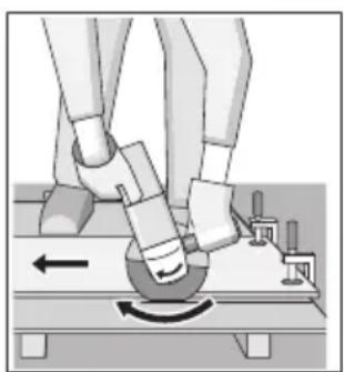
EneKtpOnHCTpyMeHTbT Tp6Ba Da Ce BODn BnHaRn NpaBaHe B o6paTHa nocKa.B npOTnBeH CnyaH cb- IecTByBa ONaCHoCT ToI Da 6bJe H3XBbPNeH HeKOHTpoNHyEmo OT cpe3a.
PpnaHa npoФnHn H ueTnpbIbHn Tpb6n HaHdo6pe n3No3BaHTe MHH
MaJIHOTO HAppeuHo CeueHHe.
P3aHe Ha KambK (Bx. qHr. A)
Pn p3ahe B kambk BHHarh OcnhypraBaTe DoCTaTbH No MoHa acnnpauchoHHa cHcTeMa.
Pa6oTeTe c npoTbONpaxOba Macka.
Onycka ce n3n03BaHeto Ha nheBMaTHuHHa HnctpyMeHT cmo 3a cyxo p3aHe/wnfoBaHe.
Pn p3aHe Ha KaMeHHMaTePnaH e Hau-Do6pe Da H3non3BaTe DnAmAHTe peKeu DNCK.
PnH3N0N3BaHeTo Ha npaxOn3CMyKBaU KoKyx 3a p3aHe C B0de7a WeHa (24) npaxOCMyKaUkata Tp8Ba Da e pa3pe-WeHa 3a H3CMyKBaHe Ha KaMeHHn npax. Bosch npednara NoDxOJaU npaxOCMyKaUKn.
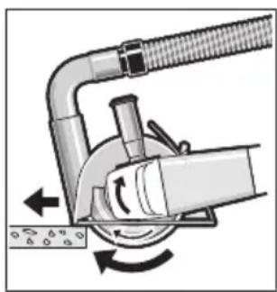
BkIOUcTe eNEKTPOnHCTpyMeHTa HTo NOCTaBeTe BbpxyDeTaHa c npEHaT auct HaBOeUaT aWeHa. PnD-BNXBaTe eNEKTPOnHCTpyMeHTa CymepeHO nOdaBaHe, cbo6pa3eHo c o6pa6oTBAHN MaTePnA1.
Pn p3aHe Ha oO6eNo TBpDn MaTePnaH, Hanp.
6eTOH C BnCOKO cbIbpxaHHe Ha YaKbI, DnAmAHTeHNrT DnCK MoKe Da npErpee H da ce Nobpei. NckPte OKoTo DnAmaHTeHrN DaNCK Ca JABEH Pn3HaK 3a TOBa.
BTo3n Cnyuay npekbcheTe p3aHeTo n octaBeTe dHaMaHTeHnA DnCK Ha npa3EH XoJ npi MaKcImaJIHn ObOpOTn 3a KpaTko, 3a da ce OxnaI.
3NaHTeHnHaMaJIeHa IpnON3BOJNTeHocT NObpa3yBaHeTo Ha BeHeU OT NCKPN NO DnCKa Ca yKa3aHn 3a 3aTbNJaBAHe Ha DnAmAHTeHn DaNck. MoKeTe Da TOr HAtouHte Upe3 KpaTKn Cpe3OBe B a6pa3INBeH MaTePnA, HAp. cnIknKaTHa TyXla.
Yka3aHnHa 3a CTAHTKaTa
Cpe3OBeTe B Hocesei CteHN ca 06eKHa cTaHdapT DIN 1053
act 1 nnn CneuФuHn 3a cTpaHata pa3npope6n. Te3n
PpeIINscaHH Tp8Ba Da ce Cna3Bat HeNpeMeHHo. PpeHi
HaJIoTO Ha pa6Ota Ta npBHeueTe OTRObOPHHa CTaHK, apXHTeKT NNI KOMNeTeHTHnra PbKOBoDInTeI O6eK 3a KOHCyUNaTae
IIa.
Yka3aHn3a ONTmAlHo 6opabeHe cakymnaTopHaTa 6atepna
IpeJna3BaIte aKymyIaTOPHa7 6aTePnI O T Bnra H Boda. CbXpaHЯBaIte aKymyIaTOPHa7 6aTePnI cMo B TempeTatyHn IHa nAzoH OT -20°C Do 50°C. HAp. He ocTaBЯTe aKymyIaTOPHa7 6aTePnI ppe3 IaTOTO B aBTOMoHn Ha cnBHe.
IepnoDnHNO nouCTBaHTe BEHTnlaQNoHHNte OTBOpHa aKymyIaTOPHaTae Batepna CMeKa uNCTa N cyXa Yetka.
CbIeCTBeHO cbKpaTeHO BpeMe 3a pa6Ota cIeI 3apeXdaHe noka3Ba,ue akymyIaTOPHaTa 6aTePnE e H3xa6eHa N Tp86Ba da 6bIe 3aMeHeHa.
CnazBaIte yka3aHnra 3a 6paKyBaHe.
PoiDbpxKaHe n cepBn3
IopdbpxkHe n nouchTahe
PpeHn Da n3BbPWBate KaKBNTO H da e DeHOCTH NO eNeKTPoHHCTpymeHTa (HaNP. TexHnuecko 06cnyXbaHe, CmHa Ha pa6oTHn HHCTpymeHT N.T.H.), KOrato ro TpaHCnOpTnPaTe Hn CBxpaHBAte, DemOHtnpaTe akymnaTopnata 6aTeprn. CbIeCTByBa ONaCHOCT OT Ha paHBAhe npn 3aJeNCTBaHe Ha NyCKOBn IpeKbCBaU No HeBHImaHne.
3a da pa6oHTe KaueCTBeHo N 6e30nacHo, noDbpaXaIte eEKeTPOHnCtpyMeHTa N BEHTNaUHOHHTe MyOTBOPH YnCTH.
CbxpaHbBaIte nCe OTHaCyTe KbM DoIbHHTeHNHTe npHnAaJIexKHOCTn rpnKlnBO.
KlneHTcKa cnyX6a n KOHCyntaunr OTHOCHOynotpe6ata
CepBn3bT Ⅲe OTROBOpn Ha Bbnpocite Bn OTHOcHOpemOHn IIOIpbjKka Ha 3aKynHeNr OTr Bac npOyKT, KaKTo n OTHOcHo pe3epBHNuactn. TOKOMNOENTHn UeptExn HnΦopMa-ua 3a pe3epBHNte uactn Ⅲe OTKpneTe n Ha:
www.bosch-pt.com
EkntnoKohcyntaun OTHOCHOyNOTpe6ataHa Bosch ue Bn NOMORHe C yDobONCTBne npn Bbnpocn 3a HauNTe npoDyKTn nTexHnte akcecoapn.
MOnJ, npn Bbnpocn n npn nopbyBaHe ha pe3epBHN qactn BnHa nncouBaTe 10-uapeHna KaTALOKeH Homep, n3nncaH na Tabekkata Ha ypea.
Блгария
Robert Bosch SRL
Service scule electrice
Strada Horia Macelariu Nr. 30-34, sector 1
013937 Bucuresti, Romania
TeN.: +359(0)700 13667 (Былгарский)
ΦaKc: +40 212 331 313
Email: BoschServiceCenterBG@ro.bosch.com
www.bosch-pt.com/bg/bg/
Дргн сервзндадесн оТкпене на:
www.bosch-pt.com/serviceaddresses
TpaHcnopTnpaHe
BkIIOUeHNTe B OKOMNJIeKTOBkata IINTHeBO-IOHHn AkymyIyTapOHn 6aTePN ca B O6XBATA Ha N3NCKBAHNrTa Ha HOpMaTbHNte DOKyMeHTn, KacaEu npOdyKTn C NOBNIseHa ONACHOCT. AkymyIaNtOPHNTe 6aTePN MoRat Da 6bDat TpaHCnpTNpaHN OT NotpeBHTeRA Na Ny6NIuHN MeCTa Be3 DoNbHNITeHN pa3peWHTeHN.
PnTpaHcnpTnpaHe O TpeTn CtpaHn (Ha np. Pnp Bb3dyweH TpaHCnOPT Hnn NpON3BaHe Ha KypnepcKu yCnyn) HMa CneunAaHH N3NCKBaHH KbM ONaKOBaHE To N 06o3HaayBaHeTo Hm. 3a ZeHTa pnp NOrTOBkata Ha NaKeTpHaTe Ce KOHCyTTpaJte cekcnpt B cbOTBeTHata Oblact.
I3npaansaateakymyataopn6baepnncmaokopnycbt Hm He e noBpehen. 3oJnpaTe OTKpHTN KOHTAKTHN KJIeMn C JIe IeIi NLeHn IN oKaOBaTe akymyataOpHnTe baepnn TaKa,
Ye Da He MoTaT Da Ce H3MeCTBaT B ONaKOBKaTa Cn. MoJa, Cna3BaIe CbIoo IdoJIbIHTeJIHn HaIIOHaIIHn IpeIINcaHHa.
БракуВанe

EneKtpOnHCTpyMeHTHe,akymyIaToPnHTe 6aTepeHHIOBbHNHTeHNHTe npncnocobHeHH Tpa6Ba Da 6bDat PpeDaBAHH 3a OON30TBoPABaHe Ha cBdbpXaUHTe Ce B TAX CypOBHH.
He n3XbpyIe eIeKtpOnHcTpymeHTn akyMynatopHN nn 6nKHOBeHN 6aTePN np6NTOBITE OTnabu!
Cama 3a ctpaan ot EC:
CbflacHo eBponeiCKa dIpeKTHBa 2012/19/EC eIeKtpoypeHITe, KOHTo He MoRaT Da ce NOn3BaT NOBeue, a CbflacHo eBponeiCKa dIpeKTHBa 2006/66/EO nobpeHn Hn H3xaBeHN oBKnHOBeHN nAn akymyNaTopHn bATEPN Tpr6Ba Da ce Cb6HpaT n PpeDaBA 3a OOn3OTBOPRAHe Ha CbDpXaUNTe Ce B TAX CypOBHHN.
AkymnyatopHH Hn 6nKHOBeHH 6aTeepHn:
JIHTHEBO-NOHHN:
MOna, cna3BaIte yka3aHnIra Tpa3dena TpaHcnpTnpaHe (Bx. "TpaHcnpTnpaHe", CtpaHnIca 234).
MaKeDoHcKn
БeЗб endocnн HanomeHn
OnuTn npedynpeyBaBa 3a 6e36eHocT ha eNeKtpnHn aHaTu
PENEy
PENEYBAHbE
IpoountajTe H CHTe HAnomeHn yNaTCTBa 3a 6e36eHNOCT.
IpeuKHe HacTaHaTHaKo pe3yntaT
OD He npDpKyBaHbe Do 6e36eHocnTe HAnomeHn UyaTCTBa MoKe Da IpeN3BbKaat EneKtpnueH yap, NoKap N/wn TeuKN IOBpeN.
3auybajTe r6e36eHNOCHHTpepynpedyBaHa ynaTCTBa 3a KopnctBe H 3a BO HDNHa.
POnMOT,eneKtpnueH anat" Bo 6e36eHocnHte npedynpeDyBaBa ce odHecyBa Ha eIeKtpnHn anapatn ITo Kopnctat cTpyja (Ka6eJcKn) nHn anapatn ITo Kopnctat 6batern (akymylatopckn).
Be36eHocr Ha pa6oTHnOt npocToP
Pa60THNOT pOcTOp OpJxByajTe ro uHCT Ndo6poOCBtIeH. IpeNoJIH NII TEmH NpOCTOpH MoKe daIOBeDaT Do HeCpeKa.
He pa6oTe co eNEKtpnHHTe anaTH BO EKcNIO3NBa OKoHHa, KaKO Ha npHMep, BO npHCycTBO Ha 3aNaNNBn TeuHOCTn, racoBN HnnpaHHa. EneKtpnHHTe aIaN CO3DaBaAT NCKPN KOnUTo MOKe Da ja 3aNaIaT npaHHaTa HnIraCOBHTe.
DpxTe rH deaTn npCytHTe nOdaNekydoKe pa60HTe co enEeKtpuH anar. HeBHMaHHeTo MoKe da npedn3BnKa da n3ry6nte KOHTpOla.
EnektpnHa 6e36eHnoct
PnKnyokot Ha eNeKtpnHOT anat Mopa da odroBapa Ha npNKnyuHncaTa. Hnkoraaw He ro meHybajte npKnyokot. He KopncHTte npKnyuHn adanTepn co 3a3emjeHnte eNeKtpnHn anatn. Hen3MeHeNTe npKnyoUcN u COoDBeTHNTE npNKnyuHnCn ro HaMaIyBaAT pN3IKOT oD cTpyen ydap.
H36erHyBaJTe TeneceH KOHTaKT CO 3a3emjeHN IOBpHHN, KaKo Ha npMep, cEbKn, paJnaTopn, MeTaNHN NaIcN IaIINHnC. NocToN 3rOJeMeH pN3NK oD CTpyEN yIap aKO BaIeTo TeNo e 3a3emJeHo.
He rHn3noxybajTe eNeKtpnHHTe anaTH Ha DoXk HnBnaXHH yCNOBn. Ako Bne3e BOda BO eNeKtpnHnOT anat,Ke ce 3rOJIemn pN3NKOT od CTpyEN ynap.
He noctanybajte hecooDbetHo co Ka6enot. Hnkorau He ro Kopnctete Ka6enot 3a Hocbe, Bneuebe nn Ncknyubahe od ctpya ha eneKtpnHnot anat. Ka6enot cybajte ro noadaneky od oran, macno, octpn HBnui nn NOBHXHN DenOBN. OHTeEHNI 3aJIneTKaHH Ka6nnr 3roJeMyBaat pniHKOT od cTpyeh ydap.
Pn pa6ota co enektpnuen anat ha OTbopeho, KopncTepe npoDOnJxeh Ka6en cooDbTeH 3a HAdBopeuHa ynotpe6a. KopncTeHeTo Ha Ka6eI cooDbTeH 3a HAdBopeuHa ynotpe6a ro HaMaIyBa pN3IKOT od cTpyEn ynap.
Ako Mopa da pa6oTHe co eNeKtpnueH anat Ha BnaXHo MeTo, KopncTeTe 3aWtHTen ypeD 3a DnpepeHunJaHa cTpyja (RCD). KopncTeBeTo Ha RCD ro HamaNyBa pN3NKOT oD cTpyeH yap.
HnHa6e36eHnoCT
BnTe BHNMaTeHn, BHMaBajTe KaKo pa60HTe n pa60Te pa3ymHo co eNEKtpuyeH anat. He KopnCTe ENEKtpuyeH anat aKO cTe yMOpHn HnN NOd DejCTBO Ha npOrn, AnkoXOn HnN NekOBn. EHeH MOMENT Ha HeBHMaHHe IDoEka pa60Tte Co eNEKtpuHnTe aHaTN MoKe Da IIOBeE Do cepNo3Ha IInuHa IIOBpea.
KopncTe He NmHa 3aWHTHb Onpema.CekoraHocete 3aHTTa 3aOuN.3aWHTHbTa ONpeMa,KaKO Ha np., Macka 3a npab,6e36eHocnYeBn KOHcEeN3raat, WlEM HnN 3aWHTTa 3aUSh, KOHcE KOpNCtAT 3a COoDBeTHN YCNOBn,Ke DoBeDaT DO HamaNyBaIbe Ha NnHn NOBpeHn.
CnpueTe HeHamephO aKTHBnpaHe. IpoBepTe daHn npEKNHyBaOT e NCKnyeH IpeD Da ro BKNyHTe BO cTpyja H/nn Co ceTOT Ha 6atePHN, IpeD Da ro 3emTe nn HocHTe anatoT. HocBe Ha eNEKTPnuHte anaTn co IpCTOT n03nIOHpaH Ha npEKNHyBaOT Hn BKnyuBaBe BO cTpyja Ha eNEKTPnuHte anaTn nnjUTo npEKNHyBaOT e BKNyueH, MoKe Da npEIN3Bnka HecpeKa.
OtctpaHete KaKOB 6nlo Kny3a perynipahe nn Phpanuckn Kny nped da ro Bknyuhte eNeKtpnHnot anat. Phanuckn Kny nnn Kny npinkayeh 3a
poTnpaKnot DeI Ha eIeKtpnHnoT aIaT MoKe da DoBeDe do IuHa Nobpeia.
He rnpueekopybajte orpaHcyBahta. Noctojano odpxbajte cooDBetHa nooX6a n paMhotexa. Oba OBO3MOxByBa IIOO6pa KOHTpOla Ha eNeKTPnHnot aIAT BO HepeBnINBn CNTyaun.
06neueTe ce cooDbetHo. He hocete wnpoka o6nka n haKHT. Kocata,anHtata n paKaBnUte Tpe6a da 6nDat noJaleky od noDBHXHnte denobu. HwpoKata o6nke,HaKHTOT HnDolraTa KOCA MoKe Da ce 3aKaayat 3a noDBHXHTE DeNoBn.
Ako ce KopncTaT noBp3aHn ypei 3a Baedebe npaunHa n co6npaBe npedMeTH, npOBepTe daHn ce npabHNO NOBp3aHn KOpNCteHN. Co6npaHeTo npaHHa MOKe Da rH HaMaHn ONaCHOCTHTe npeH3BnKaHn od Hea.
Ynortpe6a n yBaHbe Ha eIeKtpuHnte aIaTH
He ro npeontobapybajte enektpnHHOT anat. KopncTeTe cooDBeTeH enektpuH anat 3a HameHaTa. Co cooDBetNHOT enektpnuH anat noD6po, no6e36eHNo I no6p30 Ke ja N3BpUHTe pa6OtaTa 3a Koja e HameHET.
He KopnCTe eNeKTPnueH anaT aKO He MoKeTe da To BKnyuHTe H NCKnyuHTe co NOMoU Ha NpeKHyBauyot. Cekoj eNeKTPnuH anat kojTu He moKe da ce KOHTpOIIpa CO npeKHyBauye oNaCeH Mopa Da ce nonpaBn.
Hcknyute ro eNEKtpnHnot anat od ctpya n/nnn ceTOT ha 6atepnn od eNEKtpnHnot anat, nped da npabnte HekaBn npnaIarOyBaHa, MeHyBaTe dONOHHTENHa ONpema Hnro CKlaInpaTe eNEKtpnHnot anat. Co OBne npBeHTNBn 6e36eHocn MepKn ce HaMaJyBa pN3NKOT od cnuyajHO BKlyuYBaHe Ha eNEKtpnHnot anat.
Cybajte rH eNeKtpnHHTe anaTHIOdaNEky Ondofoat Ha deua H He DO3BOyBaJTe NncaTa KOH He paKyBaIe CO eNeKtpnHNot anat nHn He ce 3aNo3HaEHn Co OBA ynatCTBO Da pa60tAT co hCTnot. EneKtpnHNTe anaTHce onacn BO paTe Ha Heo6yueHn KopncnU.
OdpKyBaBe Ha eNeKtpnHn anaTH. IpoBepete ro nopamHyBaBeTo Hn npuBpcTyBaBe Ha noDbNkHnTe deNoBn, cnojot Ha denobite H cHTe pyrHu CNOBn wTO MOKe HeratNBHO da BnJaat BP3 cyHKUOnHnpaBeTo Ha eNeKtpnHnOT anat. Ako e ouTeteh, odHeceTe ro eNeKtpnHnOT anat Ha nonpaBka nped da ro KopnCTte. Mhory HecepkeC ce npedn3BnKaHn 3apadn HecooDBeTHO oDpKyBaBe Ha MOKHnTe aHaTH.
Ocptpe H uHCTe Tn anaHTe 3a ceuebe. CooDbetHO odpxyBaHNTe nBnI Ha aNaTte 3a ceuebe nomanky ce BNTkaAT I nonecHO ce KOHTpOlnpaat.
EneKtpnHnot anat, dononHntenHaT a onpema, deNoBHte H dp., KopHeTe Tn BO cOrnaCHOCT co Oba ynatCTBO, BHIMabajTe Ha pa6oTHnte ycNOBn H pa6otata Koja ja BpHnte. KopHeTeHbeto Ha eNeKtpnHnot anat 3a npHn HameHm MOKe da IOBepe DO ONaCHN CNTyaUHN.
Ynotpe6a n yBaHbe Ha 6aTePncn anat
PonHete ja 6aTepujata cmo co nonHaue HabeJeoh O npOn3BOAnTeNoT. POnHauy KoJTo e COoDBeTeH 3a eJeH TnCet Ha 6aTePN MoKe Da IpeDn3BnKa ONaCHocT O nOxap aKO ce KopuCTn 3a dpyr CET Ha 6aTeepn.
EneKtpnHHe anaTH KopncTeTe rCaMo co cpeuJanHO HameHen CTobn Ha 6atepn. KopncTeBeTo Ha npTuH ceTobn Ha 6atepn MoKe da npeIN3Bnka onaChOCT Ond NOBpeDa HnNoKap.
Kora He ro Kopncntte cetot ha 6aTeHH, cyBaJIte ro noJaIeKy od dpyrMeTAnH npEIMTe, KaKo Ha np.. cnojyBaIKn, MoHTN, KnyeBn, WajKN, 3aBPTKn HnH dpyr NoMaH MeTAnH npEIMTe wTO MOKe da npEIN3BnKaat cNoJ od eEn Do dpyr N3BOp. KpaToK cNoJ ha 6aTeepcknte n3BOpn MoKe da npEIN3BnKa n3ropeHnCu nnNoKap.
Iop HepeBHeHn OkHOCTn, TeHocTa MoKe da nCTeue od 6atepnjata; H36erHybajTe KOHTaK. Pnp cnUyaen Donnp, H3MnJte ce co Mna3 Boda. Ako TeHocTa Bne3e BO OHTe, N6apajTe DononHntHa MednunHcKa NOMoW. TeHocT HCteeuHa od 6atepnjata MOKe Da IpeDnBnKa npHTaunJa nn H3ropeHnUn.
Cepbnncpahe
EneKtpnHnot anat cepBncpajte ro kaj KBaHnФнkyBaHO nIue Koe KopnCTn cAmo HdeHTnHn pe3epBn DeIOBn. Co Oba ce OBO3MOxKyBa 6e36eHNO odpxyBaHe Ha eNeKtpnHnot anat.
Be36eHocn HanomeHn 3a aroJHn 6pycnIKN Be36eHocn npEynpeyBaHa 3a 6pycebe, mHPrnahe, XnuHo YetKaHe n abpa3HBNO ceYebe
Oboj eNeKtpuH en aIaTe hAmHeT da fynKUHOHPa KaKO anat 3a 6pycebe, WMnprnaBe, KnuHaHO YeTKaBe Hn ceYeBe. IpoounTajTe rN cHTe 6e36eHocHN ppeDynpEduBa, NlycTaPauHH CneuHkaCIN npnoXeHN co OBOJ eNEKtpuH en aIa.T peWKITE HaCTaHaTH KaKO pezIITaT Ha HeNPdPxyBaBe Do cHTe HHCTpyKuH pInIOXeHN NOOly MOKe Da npeH3BnKaat CTpyEH yap, Noxap H/INn TeuKN NobPeDN.
OnepaunTe kako Ha np. pOIpaBe He ce npenopayBa da ce Bpuat co OoJ eNeKtpuHnAnat. OnepaunTe 3a KOH He e HameHET eNeKtpuHnOT aHaT MoKe Da IpeDn3BnKaat ONaCHOCT NIIuHa NOBpeDa.
He KopncTeTe dOnonHntenHa onpema Koja He cneunjAnHO dN3ajHnpaHa H He e npenopayaHa od npOn3BOndTeNoT Ha anat. CAmO 3aToa WTo DOnONHTeHaTa ONpeMa MoKe Da ce BrpaDN BO BaUnOT eNeKTPnuEh aIaT, He 3NaU N DeKa MoKe Da ce oBe36eDn 6e36eDn Ho pa6oTeHe.
YtbpdeHa7 6p3nHa Ha dononHHTenHa7 onpema Mopa Da 6nHe HajmAnky eHaKbHa Ha MakcHMaHnHa7 6p3nHa O3NaeHa Ha eneKtpHnOaT aata. DOnonHHTenHa7 onpeMa Koja paobTo nO6p3o od ytbpDeHa7 6p3nHa MoKe da ekCnIOnpa Hda ce pacnPcKa HaceKaide.
HaBopeHnHOT nJametap n de6eHHa Ha BaWata DononHntenHa onpema Mopa da 6nde BO paMKTe Ha
Klnacata Ha Baunot eKeTpueh anar. OoHnTeHa ONpeMa co HecoOdBetHa BEnuHnHa He MoKe COoDBeTHO da ce 3aHTTN KoHTpOnIPA.
Habojot 3a MOHTpahe Ha donoONHnTeHaT Onpema Mopa Da ODRObapa Ha OCOBHaTa 3a MOHTpaBe Ha 6pychnkata. 3a donoONHnTeHa ONpema Koja ce MOHTpa Co npHpap6HnCATA, HacaehNt OTBOP Mopa Da ODRObapa Ha dHjameTapOT HA cnojhata npHpap6HnCt. IOnoONHnTeHaT Onpema Koja He e COODBeTHa Ha xapDbepOT Ha eNEKTPnHnOT aIaT He MoXe Da ODpXyBa pAMHToEka, 3apAn PpeKymepHnTe Bn6paunu MoKe Da npeDn3BnKa rSybeHe KaOHtpoJa.
He Kopnctete owteteHa dononHntenHa onpema. Ppeyotpe6a npobepete ja dononHntenHata onpema, kako Ha np., a6pa3HBNTe DnCKOBn 3a Hbepkn n ctpyrotHH, 3aHTHTATA NOIora 3a OTBOPH, ctpyxkebe HnnpetepaHO abe, XnuhaTAt YETka 3a OanabaeHH Nnnyknatn XnU. Ako eNeKTPnHnot anat HnDOnONHtENHa TOnpema naHe, npobepete daH e OwteteHa HN HCTaHnpujTe HeoWteteHa dononHntenHa onpema. IIO npobepkata HnHCTaHnpaBeTo Ha DononHntenHaTOnpema, Bne H nyreTO BO 6nn3nHa NOMcTeTe ce NoaJeKy od NobprHHata Ha potHpauKaTAt ONpema, H BKlyute To eNEKTPnHnot anat Ha MaKCHMaHa 6p3nHa 6e3 ontOBapyBaBe edHa MmHyTa. OwteteHa tdoonOHntenHa onpema Bo06NuayHo ce pacHyBa BO TEKOT Ha OBOJ TeCT Nepnoi.
Hocete NnUHa 3aWHTHa onpema.Bo 3aBnchoct od npHMeHaT, KopHeTe 7tHTNk 3a Hnce, 6e36eHocCHn Hn 3aWHTTH Ounla. Kako 7to e cooDBetHO,Hocete MACKa 3a 3aWTTa OD npauHHa, 7tHTNcN 3a yUn,paKaBnH n pa6OTnHu npectnka, KoJATo rN 3anHp aMnIte a6pa3HBn napuHbA nn NapuHbO od denot 7to ro 6pa6OtuBaTe. 3aHTiTata 3a OH MOpa Da OBO3MOXn cnpeyBaBe Ha ocTaOnu 7to ce pacnpckyBaat pni pa6OteHo.Mackata npoTbN ppab Hn peCnPaTopoT Mopa Da rN fHnTpnpa YecTHKNTe 7to ce reHepnpaAT npn pa6OteHo. DOnroptajHa n3IOKeHocCT Ha INHTEHNBHa 6uyaba MoKe Da DOBeDe Do rSybe Ha cnYxOT.
IyreTo BO Bawa 6n3Ha Tpe6a Da 6n4T OdaJeHn od pa60THOT npocTOp. Cekoj wTO BneryBa BO pa60THOT npocTOp MopA Da HOCN NnHa 3aHTHa onpema. NapuNb aO denot wTo ro o6pa6oTyBaTe nPi pacnnaHa dONoHNHeHa onpeMa MoKe da ekCnIoHa pa pacnpcka Ha da ppeH3BnKa NobpeDa HaDbop od HeNocepHaTa pa60THa NobpHnHa.
Ipxte ro eNEKtpuHnO anat 3a H30nnpaHaT a nobpunHa oDeka ceyete co dONNHTeHNaT a onpema, 3a da He Dojde BO KOHTAKT CO CKPHeHa XNuA. Ako onpemata 3a ceyebe Dojde Bo DoNHP co XNuA noD HaON, MoXe Da rH N3IOXn MeTaHnTE DeNoBn Ha eNEKtpuHnO anat POn HaON H OpeaTopoT MoXe da do6ne cTpyeH ydap.
He ro octabajte eJektpnHnot anat donydoJeKa dononHntenHaT aOnpema He 3anpe cenocho. PotpaqkaT aOnpema moKe da ja 3a4aTn nobpHnHaTa n da ro NobIeue eJektpnHnot aanT haBOp od BaSha KOHTpOJa.
He ro BknyuBajte eneKtpnHnot anatdoKea ro dpxHTE CBPTEN KOH Bac. Cnyuaeh KOHTaKT co potnpaKa dONOHNTeHa ONpeMa Moke da ja 3aKaun BaShaTa o6NeKa, co NOBNeKyBaHbe Ha DOnOHNTeHaT a ONpeMa KOH BaWeTo TeNo.
PeIOBHO uHCTe Tn BO3dUshHHe BeHTnHn Ha eNeKtpuHnOT anat. BeHTnHaTOpOT ha Motopot NOBLeKyBa npab Bo KyKnIHTeTo, a npTepeHaTa akymunaJHa Ha MeTaleH npab MoKe Da npedn3BnKa onaChoc TOn eNeKtpuHc H yap.
He pa6oTe co eNeKtpnHnot anat Bo 6n3Ha Ha 3anAHB MaTepnJann. Nckpnte MoKaT da Tn 3anaiT OBne MaTepnJann.
He KopncTeTe DoonHnTeHa onpema 3a Koja ce notpe6Hn TeuHn pa3naDyBauch. KopncTeHeTo Boda Hn npTuHn TeuHn pa3naDyBauch MoKe Da IOBeJe DO CMPT Hn CTpyeH yap.
O6nBaBe H noBp3AH npdeynpeyBaHa
Od6nBaHBe e HeHaedejHa peaKuJHa n npKLeWTeH nIi
3aKaueH potnpaKn DnCK, nOTnOpEn DNCK, YETka nIi dpyra
DOnoJIHNTeHa Onpema. PpKLeWtYBaHbeto nIi
3aKauyBaHbTo ppeIN3BkyBa 6p30 MaHeBpnpaBe Ha
poTaunOHATA OOnONHtENHa ONPema, KOe Od dpyra cTpaHa,
PpeIN3BkyBa pncnIHHO HAcOyBaBe Ha
HeKoHTPOIIpaHNot eJeKtpnueH anat BO cnpOTNBcHn PpaBeU
OD potnpaHbTo Ha ONPemata BO TOkKaTa Ha HAbayBaBe.
Ha npimep, aKO abpa3nBEH dNck e 3akaueH nIi
pnpKLeWtEH oN DeNt wTO rO obpa6OByBate, ocTpCuata Ha
DNCKOT Koja BneryBa PO npKLeWtEHa TOkA MoKe da Ce
3apne BO NOBpHiHATA Ha MaTepnjAnot n DnCKOT Da ce
PomeCTn nIi OCNoDoN. NsCKOT MoKe Da cKOKHe nIi Ond6Ne
OD ONEpApOtO, BO 3aBnCHocT Ond HacOKaTa Ha DnKHe Ha
DNCKOT BO TOkKaTa Ha npKLeWtYBaBe. A6pa3NBHTe
DnCKOBn, hCTo TaKa, MOKe Da CE nCKPwAT NOd OBHe ycIOBn.
Od6nBaHbEtO e pe3yntat Ha nOrpeSha yNoTpe6a n/nn
HeCooDbETn OpePaTHBn NoCTaKn nIi YcNOBn mOKe da
ce n36berHe co npEeMaBe Ha COoDbETnTe ppeBentHBn
MepKn npInIoXeHN nOdoNy.
Ubpcto dpxeHe ha eektpnHnot anat H no3nHOHPaBe Ha BaWeTo Teno n paka 3a da ce OBO3MOxN OTnp Ha cInIte Ha od6NaBe. CekoraW KopHCTeTne NOMOuHa paKa,doKOLky HMa,3a MaKcMAnHa KOHTpOna Ha od6BaBeTo Hn CnIaTa Ha BpTeBepn BknyBaBe. OepaTopoT MoKe Da rH KOHTpOnHa peakUHTe Ha cInIaTa Ha BpTeBepn CInIte Ha od6NaBe,doKOLky ce npe3emaat cooDBeTHn PpeBeHTNBn MepKn.
He ja ctabajte pakata BO 6n3nHa ha potnpaKaTa DOnonHntenHa onpema. IOnonHHTeHATA onpeMa MoKe da ce odne npeky Baaata paka.
He ro no3nHnpajTe BaWTo Teno BO o6NaCTa Kaede eneKtpnHnot anat Ce DnXn,doKoIky HactaHe
O6HbBe. O6HbBeTo Ke ro npnBnKn aHaTOT Bo CnpOTnBEN npaBc OD nBxKeBTo Ha NsCKOT BO TOkata Ha 3aKaUyBaHe.
06pheTne noce6HbBnMaHHe npu n3pa6oTKa Ha arnn, octpn HbNcHn Hdp. N36erHyBaJte OTCKOKHyBaBe H 3aKaUyBaBe Ha dONOpHNTeHnHaTo ONpeMa.ArInTe, OCTpHTe HbNcHn HnOTCKOKHyBaBeTO MoKe Da DOBeaT Do 3aKaUyBaBe Ha dONOpHNTeHnHaTo ONpeMa H da npEni3BnKaat rgybe Ha KOHTpOla HnIOn O6NBaBe.
He noBp3yBaJte nHa co IaHeu,ceHnlo 3a pe36ahe Ha npBO Hn nnla co 3anu.Obne ceunla npEn3BnkyBaat 6p3n OndbHa n rHybeHe Ha KOHTPona.
6e36eHnOCHn ppeynpeyBaBa cneuΦnHn 3a 6pycebe n a6pa3NBHO ceebe
KopncTe CaMo BnOBN Ha nckOBn, KOHTo ce npenopayBaat 3a BaHnot eKeTPhueH anat, H cneuΦnHa 3aHTTa dN3ajHnpaHa 3a N36paHnot DKcKbN KOnIto He ce DN3ajHnpaHn 3a daJeHnOT eKeTPhueH anat He MoXe COoDBeTHo Da ce 3aHTntat H He ce 6e36eHN.
PobpHnHa 3a 6pycebe Ha ueHTpaHnTe notchatn DnCKOBn Mopa Da ce Hnctannpa Nod paMHnHa Ha 3aHTTHNt NOKloneu. He npaBnHO MOHTnpaH nck KoJTo Ce npoterappeky paMHnHa Ha 3aHTTHaTa paMka He MoKe COoDBeTHO da ce 3aHTNTn.
3aHTATA MOPA da 6ne 6e36eHNO npuBpcteha Ha eNEKtpnHHOT anat, H COOBETHO NOCTabeHa 3a da o6e36eHN MAkchmAlHa 6e36eHocT, Taka To MNHManeHdO dNCKOT da 6ne H3IOXKeH KOH onepatopot. 3aHTATA rO 3aHTHTyBa onepaTopoT od CKPHeHTE napHbA Ha DnCKOT, Cnyaeh KOHTaKT co DNCKOT H NCKPN KOntMOKAT da ja 3anaat OBekeata.
ДИСКOBНЕ мopaда се користсамо за COODBETHN hameн.Ha npimep: He kopncteTe dNCK 3a ceuebe 3a cTpanuho 6pycebe. A6pa3nBHnTe nckOBn 3a ceuebe ce Hamehen 3a nepiФeRno 6pycebe, cTpaHnHTe cnInI ITO ce npImeHyBaAT Ha OBne INCKOB NMOKe da npedIN3BnKaat HNBHO pacnapuyBaBe.
Cekoraw Kopnctete HeoWTeEH npnpa6Hn3a 1NCKOBn co npabHnHa BEnuHnHa nΦopMa 3a Baunot H6paHnck. CooBETHTe npnpa6Hn3a DnCKOBn FOITnnpaaT DnCKOT CO wTO ce HaMaIyBa MOxHOCTa OD KpWeHe Ha NsCKOT. Pnpa6Hn3te 3a DnCKOBn 3a ceYeBe MoKe Da ce pa3NIkyBaAT oD npnpa6Hn3te 3a DnCKOBn 3a 6pyceHe.
He ynoTppe6yBaJTe KOpHCTeHN DnCKOBn Ond noroEmn enektpuHn anatn. NcK HameHET 3a IoroJIem MOKHn aIaTH He e cooBteH 3a roJIEMn 6p3HH Ha MaIIaTn MoKe Da ce pacnpchat.
DOnonHnTeHN 6e36eHocn npEynpeyBaHa cneunphuHn 3a a6pa3NBHO ceyebe
He ro "npHTnckajte" nCKOT 3a ceuebe H He npHmEnyBaJte npekymepen npHTncok. He hactoJyBaJte da HanpaBte npekymepno dna6ok 3acek. PpeONTObApYBaBeTo Ha nCKOT rOJIeMyBa ONTObApYBaBeTo N OCETNIBOCTa HA BNTKaHbe H
HaBaIyBaHBe HaДNCKOT Bo 3aceKOT IN MOXHOcTa 3aOДБИBaHBe IIN KpIeHBe HaДNCKOT.
He 3actaHbajTe Bo HnHjna 3ad potnpauKnot dNCK. Kora nckot,Bo tekOT Ha onepaunjata,ce DnKn noJaIeKy od BaIeTo TeNo,OnBnBaIeTO MoKe Da ro npdBnKn potnpauKnot nck N MOKHOT aIaT DnpeKTHO KOH Bac.
Kora nckot ce habanyba nn Kora ro npeknhyba ceyebeTo 3apaHn Hekoja npuHa, Ncknyete ro anatot H dpkTe ro HnoBHexe DoEka nckot cenocho he 3anpe. Hnkoraaw He hactojybaje da ro 3BaIHTe nckOT 3a ceuebe oJ 3aceKOTdoEka ce DBHXN Hn MoKe Da OJDe OO6nBaHe. PpOBepet E npesMeTe IoppaBHO JeCTBO 3a da ja eINMHnpaTe npuHnTa 3a HaBanyBaBe Ha nCKOT.
He 3anoHyBajTe NOBTOPO Co Ceuehe Bo IeIOT To ro 06pa6OToVBate. PouekajTe DoKeKa NcKOT Da DOCTHnHe cEnoCha 6p3nHa N BHMaTeHNO Bne3eTe NOBTOPO BO 3aceKOT. INCKOT MoKe Da ce HaBaII, PnIDBnKn nn O6Be aKO rpeCTaTnpaTe MOKHnOT anat BO DeIOT To ro 06pa6OToVBate.
Iotnpete rnnnoHTe HnnpereonemHOT deIto ro 06pa6oTyBaTe 3a da ro hAmalnte pn3HKOT O npNKleTuBaBe nO6NBaBe Ha NCKOT. TOnEMtE DeIOBnTo rN o6pa6oTyBaTe ce NcKpNByBaat NOcBOjata TeXHa. IotnnpaHTe Mopa da ce CTabat NOd DeIOT To ro 6pa6oTyBaTe NOKpaj LInHjata Ha 3aceKOT INOKpaj HBucaTahA DeIOT To ro 6pa6oTyBaTe Ha DBeTe CTpaHn Ha NICKOT.
KopncTeIOnOHHTeHH MepKn 3a IpeTnA3HBOCT Kora npabnte "ueben 3acek" BO nocToeukn SNDOBH Hn dpyrncnnoBpHnn. KmMaB DnCK moKe da npceye ueBkn 3a rac nn BODa, eJeKTPnuHn JxuN nn npdeMeTH KO NMOKe Da npedn3BnKaat O6nBaHe.
Be36eHocn npdeynpeyBaBa cneuΦnHn 3a mHrpnahe
He Kopnctete nperoIema WMnprna. CneTe rnyaTcTBata Ha npOn3BODHTeNTe, kora 6hpate WMnprrna. ToneMnte WMnprrn KOJ haNIMHyBaAT NOIOrTa 3a WMnpraBe npeTcTaByBaaT OAnCHoc T MoKeJa PpeIN3BnKaat 3aKaUyBaBe, KInHeBe Ha DnCKOT nnO6NBaBe.
Be36eHocn npepynpedyBaBa cneuΦnHn 3a XnuaHO ueTkahe
BHHMaBajTe 6nnejKu YeTKaTa NcΦpNa XnuaHb BnakHa Dpyn H3a BpeMe Ha BOo6naueHn Onpaun. He rN npeontobayBajTe XnHTe Co npeontOBapyBaHe Ha ueTkata XnuaHte BnakHa MoKe IecHO Ja HabIe3aT Bo 06NeKa H/nn Koxa.
Ako ce npenopayBa KopncTebe Ha 3aWTHTa 3a XnuaHO yetKaBe, He Do3BonyBajTe nonpeCyBaBe MeIy XnuaHNot DNCK HnN YETKaTCo 3aWTHTa. XnuaHnot DNCK HnN YEtKa MoKe Da ce npoWhpaT Bo DnJaMeTap 3apaNi pa6OTHO ONTOBapyBaBe n CHTpnDpyraHnnte cnII.
DOnonHnTeHN6e36eHocn HanomeHH

Hocete 3aHTTHO uHa.
KopncTe COoBcTHN ypeH 3a npe6apyBaHe, 3a da rH npohajTe cKpneHnTe eKeKtpuHn Ka6n Hn KOHCyItnpajTe ce co IokanHOT npetnpjathe 3a chabdyBaBe co eKeKtpuHa eheprJa. KohtakTcO eKeKtpuHn Ka6n MoKe Da IOBeDe Do IooKap N CTpyeH yap. OwtetyBaHTo Ha racOBOn MOKe Da IOBeDe Do ekCnNo3nJa. HabneryBaHTo BO BDOBOHN ueBKN npedn3BnkyBa OwTeTyBaBe.
He rH dOnnpaJTe 6pycHnte nNoU H NnCKOBHTe 3a ceuehe dopeka He ce onaat. IIOuHte 3a BpeMe Ha paBoTeHBeTo cTaHyBaat MHOry KeuKn.
De6nokpajte ro npeknHyBaoy3a BknyuBahe/ ncknyuBaBe H CTABeTe Ro BO no3nju Ha NcknyeHo, DOKONky ce npkeHHe HanojyBaBeto Co ctpya,Ha np. NO BAede He aKymnaTopoT. Co Toa Ke cnpeuHte HeKOHTpOInpaHO pectaptnpaHe Ha ypeIoT.
3aucbpcte ro napyeTo wTo ce 6pa60TyBa.1OKoIky ro 3auBpCTHTe co ypei 3a 3aTeHyBaBe nIn MeHrEme, torawnapyeTo wTo ce 6pa60TyBa ce dpxN pOcBpctO otKoIky co BaWata paka.
Pn OwTeYBaBe H He npOnncha yNoTpe6a Ha 6aTepnjata MoKe Da n3ne3e naPea. Batepnjata MoKe da ce 3anann da ekcnnonpa. Bhece TcBex BO3dyx N DOKONky HMa NobpeHn OJHeCeTe rHa Jekap. Papeata MoKe Da rH NaPa3HN dNshHTe natuTa.
He ja otbopajte 6atepnjata. Nocton onacnoct od KpaTOK cnoj.
Batepnjata moke da ce owtetn od octpnte npedmetn KaKo Ha np. KInHcN Hn OdBpyBaU Hn Co HnbopeWNo BnJaanHe. Moke da doje Do BVnatpeweh KpaTOK cnoj n Batepnjata moke da ce 3anAa, da nyuTn qad, da ekCnIIOnpa nn da ce nperepee.
Kopnctete ja 6atepnjata cmo BO npoh3BOdn od npoh3boHntenot. Camo ha Toj hauin 6atepnjata ke ce 3aHTIN oD onaCHO ppeontOBapyBahe.


3awtntete ja 6atepujata od tonnna,Ha np. OJ donroptpajno h3noxybahe Ha cohueBN 3paun, oran, HeuHCTOTHN, BODa H Bnara. Hnaky, nocton onacHocT od ekcnnozja n Kpatok cnoj.
Опнс на пОНЗВODOTи nepформансinte

IpouHTajTe rH cHTe 6e36eHocHN HAnOMeHN uYnATcTBa. IpeKInTe HaCTaHaTn KaKO pe3yNTaOD He npHpIXpXyBaHe Do 6e36eHOCHTe HAnOMeHN uYnATcTBa MoKe da IpeDn3BnKaat eNeKtpnueH ydap, Noxkap N/nn TeuKN NOBpeIN.
BHHMaBaJte Ha cInKHe BO npEHNOT dIe Ha yNaCTBTO 3a KopnCTeBe.
Ynotpe6a co cooDbetHa HameHa
EneKtpnHnot anat e HameHET 3a ceyebe,6pycebe, rpy6a o6pa6oTKa n yetkahe Ha MeTALH MaTepnjAIn 6e3 ynoTpe6a Ha B0da.
3a cehe co KOMno3HTn6pync npedCTBa mopa da ce Kopncn cneunjnaHa 3aunTnHa xay6a 3a cehebe.
PnCeueHeTo BO KaMeH nOprnKeTe ce 3a IOBOHOBMyKyBaHe Ha npaBtA.
Co 03B0eHHTe aIaTH 3a 6pyceHe eNeKtpuHnO t aIaT MoKe Da ce KopHCTn 3a 6pyceHe co 6pycha xapTuJa.
NynctpnpaHKOMnoHeHTN
HymepnpaHbTo Ha cInKHTe CO KOMNoHEHTe OdHeCyBa Ha npKa3OT Ha eEnkTpnuHnot aHa rpaqNkaTc TpaHua.
(1) Noc3aOTKnyyBaHBe Ha 3aWTHTNHOKanak
(2) Konque 3a 6noKpaHbHe Na BpeTeHOTo
(3) Ctpenka 3a npabeu Ha BpTeHe Ha KyKnIeTeTo
(4) IpeKnHyBau 3a BKnIyUyBaHbe/NckNpyBaHe
(5)ПрикадаHa coctoj6aTa Ha HanonHeTOCT
(6) BaTeepnja
(7) Konque 3a KoHTpOHa Ha 6pojTo Ha BpTeKn
(8) Konue 3a otKnyyBaHe Ha 6aTepnja
(9)Дононтелна paчka (изолпа на поршни на paчka);
(10) 3aunTeH Kanak 3a 6pyceHe
(11) PpHKnyHa npnpa6Hnca co O-npCTe
(12)Брусна плоча
(13) 3aunTeH kaan 3a cehe
(14)ДиСКЗа ceueHbea)
(15) Nohuecta nnoya oT TBpD MeTan
(16) Bp3o3aTe3Ha HABPTka co npkau
(17) BpeTeHo 3a 6pyceHb
(18) 3aunita 3a pautee
(19) Г汞men Б汞сен ДИСКa)
(20)БpyceHnCTa)
(21) Tpkane3Ha HApBpTkαa
(22) ΦHuecTa ueTka
(23) PaçaKa (H3OJIInpHa Na IOBpShHa Ha DpShKaTa)
(24) Kanak 3a BCncyBaHbe 3a ceuehe co IIN3raUKN BOINIKn a)
(25)ДиJaMaHTcKNДИСКЗаceYeHea
a) NlyctpnpaHATA HN ONHuaHa ONpema He e den oCtAndapHHOT o6em Ha Hcnpaka. LcnocHata ONpema MoKeJa ja HajdeTe BO Hauata Pporpama 3a ONpema.
Texnukn nodaToCu
Aronha 6pycnilka AdvancedGrind 18
BpojHaDen
3603 CD9 0..
TpajHo CBeTIO 2x3eNeHO 33-66%
TpajHoCBetno1x3eNeHo11-33%
BaBHO TpeNkAbe Ha CBETnTo 1 x 3eNeHo ≤ 10 %
3-Te LED-CBETHKNHa npHKa3OT 3a HANONHETOCT6p30 Tpenkaat,doKoKny Temnepaypata Ha 6atepnjatae HauBOP od oncerot Ha pa6oTHa Temnepaypota od-30 do +65^ n/nnn pearnpa 3awTHTata od npeontOBapyBahe.
MOnTnpaBeHa3aWHTEn ypeI
Ppe6nKakBa HHTepBencnaJa ha eneKTpnHnot anat (Ha np. OdpKyBaBe, 3ameHa Ha anat nTH.) KaKO n npHerOB TpaHCnopt N cKnadnpaBe, n3BaTe ja 6atepnjata OD hero. Pn HeBNMaTeNHO pntTnCKaBe Ha npEKNHyBaOT 3a BknyyBaBe/ NCKnyyBaBe nocToI onaCHOCT ON NobpeNi.
Hanomeha: IokpseHbeto Ha 6pychata nlova 3a BpeMe Ha pa6oTATA nn npn OwTeYBaBe Ha ypeDTo 3a npnФaT Ha 3aHTHa xay6a/eNeKtpnUHnot anat, Toj Mopa da ce npaTH BO cepBnCHa Tcny6a, 3a aDpcata NOrneHHe Bo DeNoT „CepBncha Cny6bA n COBETn npn KopncTeHbe".
3aunnten Kanak 3a 6pycebe
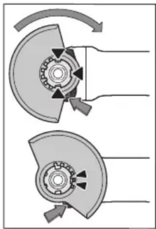
CTaBeTe ro 3aUHTHnOT KanaK (10)Ha npuΦaTOT od eNeKTpHuHnO aIaT,doEka KOINpaHnTE 3aIuHa 3aUTHTHnOT KaNk He ce NOKJlonat CO npuΦaTOT. PnToa, pNTnCHeTe ro n DpxKeTe ro NoCTOT 3a OTKnUyBaHe (1). PtTHcHete Ro 3aUTHTHnOT KaNk (10)Ha rPLOTO Ha BPeTeHOTO DoEka BeneCOT Ha 3aUTHTHnOT KaNk He IerHe Ha npipa6HnCuTaHa eNEKTPuHnOT anat IN BpTeTe
ro 3aHTHNOt KaNak DoNeKa He OcTe DeKa Ce BKNoHn.
PiOecete ja no3uJata Ha 3aHTHTa xay6a (10) cnopei
notpe6nte Ha paBToHnT npoEc. PnTOa, nPnTHcHete ro
IOCTOT 3a OTKnyUbaBe (1) HArope N 3abTpTe Ro
3aHTHTHnT KaNk (10) BO cakaHaTa No3uJna.
Cekoraaw noctabybajte ro 3awtntnhot kanak (10) Taka wto Dbata 3anuHa nocot 3a otknuybahe (1) BO COODBETHHTe OTBOPn Ha 3awtntnhot kanak (10)Ke Bne3aT.
Noctabete ja 3aawthtata xay6a (10) ha toj hauHH wto Ke ro cnpey netaheTo Ha nckpn BO npabeuc Ha IInuTeo wto ja KopnCTH.
3aHTHnT KanaK (10) cMee da ce BpTH caMo co npHTNcKaIbe Ha loCTOT 3a OTKnUyBaIbe (1)! Hnaky, eNEKTPnHHot anat He cMee da CE KOpHCTn MopA da ce npedeAte Ha cepBnchata cnYk6a.
Hanomeha: KoIpaHnTe 3aIuHa 3aHTnTHNt Kanak (10) rapaHTnpaaT, dka Ha eIeKtpnHnOt aIa MOnKe da ce MOHTnpa caMo eJeH 3aHTnTeH Kanak To My oJroBapa.
3aunthxay6a3ceyebe
PnCeueheTo CO KOMNo3HTH6pycHn CpeIcTba ceKoraaw KopHeTe ja 3aWTHHaTa xay6a 3a Ceuehe (13).
PnCeHbTo BO KaMeH nOrpHXeTe ce 3a DOBONHO BmkyBaHe Ha npaBtA.
3aHTnTHata xay6a 3a ceuehe (13) ce MoHTnpa KaKO 3aHTnTHa xay6a 3a 6pycehe (10).
Xay6a 3a BImykyBaBe npn ceuebe co IIN3raUka BOUNka
3aHTHaTa xay6a 3a ceueHe co IINrAguKN BOINK (24) ce MoHTnpa KaKO 3aHTHa xay6a 3a 6pyceHe (10).
DononHntHa paKa
KopncTeRoBaunoteneKtpuueH anatcmo co dononHntenpa4ka9
HaBPteTe ja IOnonHnTeHnata paKa(9) od DecHO nn OJneBO Ha nOroHcKaTa rnaBa BO 3aBnCHocT od HauHHOT Ha pa6ota.
DOnonHnTeHa paKa 3a npduyBaHe Ha Bn6paunthe

HaBpTeJe ja
IOnoJIHnTeHnHaTa paKa (9)
OJ DecHO nn OJ neBO Ha
NOrOHckaT Ta nBa Bo
3aBnCHOCT OJ HaunHOT Ha pa6oTa.
IOnonHnTeHnata npka 3a npduyBaHe Ha Bn6paunTe OBO3MOxBya pa6oTeHbe co Mann Bn6paunn n npjuTaHa n 6e36eHa pa6ota.
Bo Hnkoj cnyuj he ja meHybajte dononHHTenHaTa pauka.
He ja kopncTeTe oWTeTeHaTdoONHHTenHa Dpka.
3aunra 3a nHaKnTe
3a pa6oTeBe co rYmEn dNcK 3a 6pyceBe (19)mHn co nOnueCTa YETKa/nnOueCTa YETKa/nAmeneCTa 6pycha nNoa cekoraaw MOHTHpajTe ja 3awHTTaT a paute (18).
3aucbpcTeJe ja 3aunTnTaTa 3a paueTe (18) co doonolnntenHaTa paKa (9).
MOHTnpaBe Ha 6pyChn anatn
Ppe6nlo KaKbA HHTepBHeuJa Ha eEnktpnHHot anat (Ha np. OdpKyBaBe, 3aMeHa Ha anat nTH.) KaKO n npH HerOB TpaHCnOpT NCKlaHnpBe, N3BaTe je ja 6atepnjata OD hero. Pn HeBHnMaTeNHO pnttckaBe Ha npEKNHyBaOY 3a BkNpyBaBe/NCkNpyBaBe NOCTOn ONaCHOCT OI NOpeNi.
He rH donnpajTe 6pychnte nnoyn n dnckOBte 3a ceuebe dokeKa He ce onadat. IIOuHTe 3a BpeMe Ha paBoTeHBeTo cTahyBaat MHOry Kekn.
IcHCTeTo BpeTeHOTo 3a 6pyceHe (17) n CHTe JeIOBn 3a MOHTnpaHe.
3a 3aBpctyBaHbE H Ola6aByBaHbHe Ha 6pyCHte aHaTHn
PHTNCHETe Ro KOnUeTO 3a 6IoknpaHb He BaPeTeHOTo (2), 3a
Da Ro 3aBpcTHe BpeTeHOTo 3a 6pyceHe.
PHTHCHETe rO KOnUeTo 3a 6noknpaBe Ha BpeTeHOTcMo KOra BpeTeHOT 3a 6pyceBe e BO coctoJ6a HmpyBaBe. NHaKy eNeKtpuHnot anat MoKe da ce OHTeTn.
Bpycnn nnoyn/6pycnn nnoyn 3a ceyebe
BHHMaBaJTe HaДиМeH3NHTe Ha aIaTHe 3a 6pyceHe.
ДиjametapotHaДунkaTаMopaДаОДROBapaHa npNKnyuHaTa npnpa6Hua. He KopncTeTe aanTpepn HIn peDyKTopn.
Pn ynoTpe6ata Ha nJaMaHTCKNte 6pycnn nNoyn 3a ceuehe BHHMaBajTe Ha Toa, CTpeKkata 3a npabeOTo Ha BPteHe Ha nnJaMaHTckata 6pycna nNooya 3a ceueHbe Da ce NOKIOnyBa co npabeOTo Ha BPteHe Ha eNeKtpnUHnot anat (norneDHe ta CTpeKkata 3a npabeCn Ha BPteHe Ha KyKnUTeTO).
PeOocIeIOT Ha MOHTaXkata MoXe Da ce BnIHa rpaΦnUkata KapTa.
3a npuBpcTyBaHbe KopncTeJe ja 6pychata nnoa/ndckot 3a ceuehe 6e3 dpyrn anatn co 6p3o3aTe3HaTa HABPTka (16).
Брзоатэзната Habртka (16)cмeeJa ce KOpнстma mo 3a 6pychn nIoou nHn dNcKOBn 3a ceuebe.
KopncTeTe cmo 6ecnpekOpHn, HeoWTeTeHH 6p303aTe3HN Habptkn (16).
Pn3aterHyBaBe BHHMaBajTe Ha Toa,CTpaHaTa co HATNc Ha 6p3o3aTe3Hata HABptKa (16) da He NOKaKyBa KOH 6pychata nloya.
3a npuBpctyBahe Ha 6pychata nnoya/ndckot 3a ceuehe KopncTe je ncknyuHBO nCnpaHaTa 6p303ate3Ha HABrKa (16).
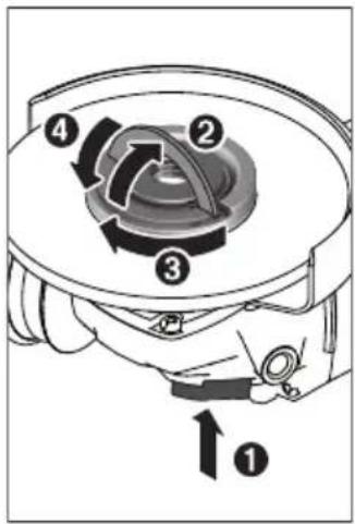
PnTHcHTe Ha KonUeTo 3a
6IOKpaIbe Ha BpeTeHOTo
(2),3a Da Ro 3auBpcNTte
BpeTeHOTo 3a 6pyceHe.3a
da Ja 3auBpcNTte
6p303aTe3HaTaha HApTka
(16),OTbOpTe Ro HaRope
dpxaOt Ha 6p3o3aTe3HaTa
HaBPtKa n CBPTeJa CnHNO
BO pPaBeu Ha CTpeKInTe Ha
yacOBHHKOT. Notoa
npeklonete Ro HADony
dpxaOt 3a fHKcnpaHe Ha
6p3o3aTe3HaTahA HApTka.He
e DOBONHO 3aterHyBaBe
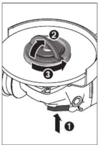
Ha pa6oT Ha dmckot.
Ipornncno npuucbpcteHaTa HneouTeHa 6p3o3aTe3Ha HABPTka (16) MoKeTe da ja oJababnte co paka. 3a Toa OTBopete r Ho rOpe dpXauOT Ha 6p3o3aTe3HaT AHBPTka n CBptete ja CnHOb BO npaBeC npoTHBO Ha CTpeKNTe Ha YacOBHKOT. LBCPcTO 3aterHaTata 6p3o3aTe3Ha HABPTka HNKOraHi He ja ODbpyBaJte co anat, Tyky ynotpe6e Tkny CO DBA OTBOPN.
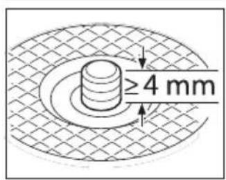
IIO MOHTaKaTa Ha
IpnKnyHaTa npRupa6Hnca
Ha 6pycHa Ta NIoUa/
DnCKOT 3a CeueHe
CNo6oHaTa DoJxHa Ha
HaBoJoT Ha 6pyChTo
BpeTeHo Tpe6a Da H3HecyBa
HajMaKnky 4 mm.
BHHMaBaJTe Ha cBpCTo BkIOnyBaHc Ha aIaTOT 3a 6pyceHe, Taka ITo HeMa Da Ce OdBPTN OD BpeHoTo Ha KpaJOT oI eNEKtpnHnO t anat.
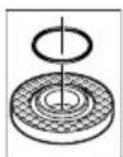
Bo npknnyuHaTnpnpa6Hua (11) okony
BHeueoT 3a ueHTpnpaBe e cTaBeH nlaCTnueH
en (O-npcTeH).Dokonky HeoocTHra O-
npctehOT Hn e oWTeH, npknuyHaTa
npnpabHua (11) Mopa da ce 3ameHn ppe
noHaTaMoUHa yIOTpe6a.
P MoTaxaHa anatot 3a 6pycebe, nped BknyyBaBeTo, npOBepTe daHn Toj e TocHo
MOHTnpaH N daH MoKe Cno6oJHO da Ce BPTN. IpOBepeTe daH anatot 3a 6pyceHe He cTpyra Ha 3aHTTHata xay6a Hn dpyrHte DeNoBn.
Iamenecta 6pycha nnoya BO BnHa nee3a
Pn pa6oTebeTo co naMeNecta 6pycha nnoa ceKoraw moHTnpajte ja 3awHTata 3paueTe (18).
TymenDnck3a6pycehe
Pn pa6oTebeTo co rymen dNCK 3a 6pycehe (19) cekoraaw MoHTnpajte ja 3awHTnTa 3paueTe (18).
PeioceIOT Ha MOHTaKaTa MoKe Da ce BnH Ha rpaΦnKaTa KaPa.
CTaBeTe rTo rymeHnO7 6pyceH nIcK (19) Ha 6pyCHOT BpeTeHO (17).
Ubpcto npitncheTo 6pycHnot nCt (20)Ha donHaTa cTpaHa Ha rymeHnot 6pyceH dNCK (19).
Habptete ja Tpkane3HaTa HABPTka (21) n 3aterheTe ja co Knyu co Dba OTBOpn.
Nohucta yetka/nnoctca yetka
Ppna pa6oteheTo co noHuecta nn nnoeCTa yeTka ceKoraaw MoHTnpajte ja 3auTnrtata 3paute (18).
PeioocneIOT Ha MOHTaXkata MoKe Da ce BnH Ha rpaΦnUkata KapTa.
IOnueCTata/IIoueCTata ueTka Mopa da ce HaBPtn Ha BpeTeHOTo 3a 6pyceHe IdoKe UBPcTo He HaneRHe Ha npPabHnucata Ha BpeTeHOTo 3a 6pyceHe Ha Kpajot Ha HABojOT Ha BpeTeHOTo 3a 6pyceHe. 3aterHete ja IOnueCTata/IIoueCTata ueTka CO BNyUkact Knyu.
Iohuecta IIOOa OZBpCT Metan
Ynotpe6ata Ha noHuecta nnoa e do3BoneHa cmo co COoDBetEn 3auTHTEN KANK.
D03B0JEnn anatn 3a 6pycebe
Moke da hn Kopncntte cnte aata 3a 6pycehe HaBeHn BO Oba ynaTcBO 3a ynoTpe6a.
D03BOJENOT 6poj Ha BpTeKn [min-] Odn. nepHepHaTa 6p3nHa [m/s] Ha yNtpe6eHnO t anat 3a 6pyceHe MOp a Da oIRObapa Ha nOdaTOUHTe BO cIeHata TaBena.
3aToa BnMaBajTe Ha 03BoJeHnO6poj Ha BpTeXn OHN. nephephata 6p3nHa Ha etHKeTaHa aIaNtO 3a 6pyceHe.
| Maxc. [mm] [mm] | ||||
| D bd [min] | -1] [m/s] | |||
| b | 115 | 7 | 22,2 | 11500 80 |
| 125 | 7 | 22,2 | 11500 80 | |
| D | 115 | - | - | 11500 80 |
| 125 | - | - | 11500 80 | |
7530M141150045
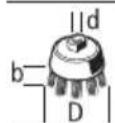
BcncyBaHe Ha npab/ctpyroTHH
IpaBtO od MaTePnJaJIte KaKo Ha np. cNoeBn 6oja, HeKoN BNDOBn DpBO, MNHePaII N MetaI MoKe Da 6Hne 7tETha No 3dpabjeTo. IOnnpaBeTo HIN BnWbYBaBeTo Ha TaKBaTApaB MoKe Da npedn3BnKa aIeprNCK peAkuN n/nn 3aBonyBaHa Ha dNshHIne NaTHTa Ha KOpNCHKOT nn Nn OkONHaTa.
OdpeneHueCTnKn npaB kaKaHa np. npaB od da6 nnn 6yka Baxat kako KaHcepoReHH, ocobeno DOKoNky ce BO KOMbHaunja co DoonHInTeHN cyntaHcN (Xpomat, cpeCTBa 3a 3aHTNa Ha dpBO). MaTePnJaHte WTo COpaXaT a36eCT CMeat Da 6nDat o6pa6otYbaHn caMo od CTpHa Ha ctpuHn Nua.
-Погрикete ce 3a Добра пюветpeнoct ha pa6oTHOTOMECTO.
- Ce npenopauyBa HocHe Ha MacKa 3a 3aIITTa npn BnIyBaHbeto Co KnaCa HaФntep P2.
BHMaBajTe Ha BaKeukite npOnHc Ha BaWaTa 3emJa 3a MaTePnJanoT KoJ ro o6pa6oTyBaTe.
H36erhybaje co6npahe npab Ha pa60HTO mecto.
BkIyBaHe/HckIyBaHBe (4)HaHaPpeH NaOly DoKeKa He ce BKnOPI.
3a da ro ncknyuHTe enektpnHnoT aat, ocno6oTe ro npkeHHyBaOT 3a BknyuBaBe/ncKnyuBaBe (4) oH. dOKoNky Toj e 6loKnpaH, KpaTko npHTncHeTe ro npkeHHyBaOT 3a BknyuBaBe/ncKnyuBaBe (4) HaHa3aH aOly nnoto ocNo6oTe ro.
Ipeynoptpe6ata npOBepTe rHa anatte 3a 6pycebe. Anaot 3a 6pycebe Mopa da 6nde MOHTpanh 6ecnpekopno n da moKe cnOboHO da ce BPTN. Hanpabete npo6a od hajmanky 1 MNHyta 6e3 onTOBAPyBaBe. He KopHCTe oWtTeHN, HETPKANEHN mHn anATn 3a 6pycebe wTO BN6pnpaaT.
OuTeHnTe anaTHa 6pyceHe moKe Da nyKHAT n da npEun3BnKaat NOBpeHn.
3aunnta od pectaptnpahe
3aWNTATA OJ pectapTnpaBe rO cnpeyuBa HeKoHTpOJIpaHOT BknyBaHe Ha eNeKTpnHnOt anat no npeKNHa CTpyja.
3a NOBTOPOB KnyuBaBe CTaBeTe rIpeKHyBaOT 3a BknyuBaBe/NCKyuBaBe (4) BO NCKnyeHa No3njuA OJHOBO BKnyeTe rEneKTpHNoT aNt.
KoHCTaHTHa eNeKtpoHMka
KohctaHTHata eEeKtpoHnka dpxN nocTojaH 6pOJ ha BpTeXn npn npa3EH oN nONTObApyBaHe n OBO3MOxyBa nCTa noctoJaHa jaUnHa npn pa6oTeHeto.
ΦHHCTapT
EneKtpoHcKnOT fHn CstpT ro orpaHnuyBa BpTeXHnOT MOMeHT npBknyBaHe n TOrJeMBya pOKOT Ha TpaHBe Ha MOTOpOT.
OndyeBaBe Ha 6poj Ha BpTeKn
Co BPTINBOTO KOnue 3a OndpeyBaBe Ha 6pojOT Ha BpTeKn (7) MoKeTe Da ro H36peTe Ntpe6HnOt 6poj Ha BpTeKn 3a BpeMe Ha KopncTeHBeTo Ha aIaNToT. IpaToUHTe BO npIOJKeHaTa Tabena ce IpenopauaHN BpeHocTH.
HaNoMeHH 3a ONTHMaHNO KOpHcTeBe Ha 6aTePnHTe
3aunthe te ja 6atepujata on Bnara n Boda.
Cknapjte ja 6atepujata Bo rpaHnHa TeMnpaTypa od- 20^ do 50^. He ja ocTabajte 6atepujata Ha np. BO ABTOMOBNOIOT BO JETO.
IobpemeHo uHCTe Tn OTBOpHe 3a npoBepyBaHe Ha 6batePiata co MeKa, uNCTa n CyBa YeTka.
CkpateHTo BpeMe Ha pa6oTa No NOnHeBeTo NOKaKyBa, DeKa 6aTeprjata E NotpoWeHa H Mopda Da ce 3aMeHN.
BHHMaBaJTe Ha HAnOMeHnTe 3a OTCpaHyBaBe.
OdpxuBaHne n cepBnC
OdpxkyBaBe n uHcTeHe
Ppe6nlo KaKbA HHTepBENuJa Ha eNEKtpnHnot anat (Ha np. ODPxvBaBe, 3ameHa Ha anat nTH.) KaKO n npH erOB TpaHcnpT N cKnadnpaBe, N3BaTeje ja 6atepnjata OD hero. Pn HeBHMaTeHNO npNTnCKaBe Ha npEKNHyBaOT 3a BkNvyBaBe/ncKnVyBaBe NOCTOn ONaCHOCT OJ NOBpeNi.
OdpjxBajTe rH uHCTn eNEKtpuHnot aNat n OTbOpHTe 3a npOBetpyBaHe, 3a da MoKe do6po n 6e36eHno da pa6oHTte.
CknadnpajTe n TpeHpajTe ro npnbopot co BnmaHne.
CepBncha cnyX6a n coBEt n np KOpncTeHe
CepBnchata cnyk6a Ke odroBOpn Ha BaunTe npaaBa Bo Bpcka co nonpaBkata n odjkyBaBeTo Ha Baunot npOn3BOD kako n pe3epBNHTe DeIOBn. O3HaKn 3a ekCnlo3nja n HOpMaun 3a pe3epBNHTe DeIOBn NCTO Taka Ke HajdeTe Ha: www.bosch-pt.com
TMMOT 3a COBetyBaBe npn KOpncTeHe Ha Bosch Ke Bn NOMOHTIOKOLKy HMaTe IpaShaHa 3a NaHInTe PpOn3BDoN n Onpema.
3a cIte npaaHa n HapaKn Ha pe3epBn DeIOBn,Be MoIIme HabeTe ro 10-ncpeHnoT 6poj od CneuNkauNoHaTa PLOUka Ha npOn3BODoT.
Cebepha MaKeDoHnJa
Д.Д.Еnéктpres
CabaKobauBn47Hb,6poj3
1000 Ckonje
E-nouta: dimce.dimcev@servis-bosch.mk
Интөрнт: www.servis-bosch.mk
Ten./φακc: 02/2467610
Mo6.:070595888
Д.П.T.Y“POJKA"
JAHN LykpobcKn 66;T.LA BToKOMaHa nokan 69
1000 Ckonje
E-nowta: servisrojka@yahoo.com
Ten: +389 2 3174-303
Mo6: +389 70 388-520, -530
IOnonHntenHa aDpeCh Ha cepBnch MoKe Da hajTe noi:
www.bosch-pt.com/serviceaddresses
TpaHcnpT
IHTHM-JOHCKNTE 6aTePNI NOJnExKAT Ha 6apaHaTa Ha 3aKoHOT 3a onacn MaTePnJaII. BatePNTe MoKe Da Cc TpaHCnOpTnPaat cAmO oD CTpaHa Ha KOpNCnKOT, 6e3 NOTpe6a Od IOnONHnTeHN KBaINΦnKaUuN.
Pn npenoc Ha nctte oCtpaHa Ha TpeTnIuca (Ha np. Bo3dyweH TpaHcnpT Hn HneDnJa) HeonxOndo e da ce BnMaBa Ha CneJalHnte HanomeHn Ha am6aJakata n O3HaKHe.Bo TaKOB cnyuj, pni noDrTOBkata Ha npTaKaTa Mopa Da ce NobiKa ekCepT 3a Onacn Cyntaun.
TpaHcnpopajte r6baTepeHnTe cAmOdoKoNky KyKnHTeTo e HeoHTeHo.3aIeneTe rNOTBOpEHnTe KOHTaKTn I
cnaKyBajTe ja 6aTeepnjaTa Ha Toj HauHn ITo Hema Da ce DnHex BO aMbaJxata. Be MoJIme BHMaBajTe Ha EBeHTyaHnTe DOJOnHnTeHN HaCuHOHaHn IpOncn.
OTctpaHyBaHe

EneKtpnHnTe anapatn,6aTeepHnTe,opemata n am6anaxnTe Tpe6a da ce otctpaHaT ha ekOLOsKn npdpatnB haunH.
He nФрлajte eNeKtpnHHTe anapatn 6aTePnHTe BO DOMaShHaTa KaHTa 3a r6pe!
Camo 3a 3emjnte od EY:
CnopeeBpOncKaTa perynatna 2012/19/EU
eneKtpnHHe anapatN To ce BOH ynoTpe6a n deFeKeTHne
Hnn NcKOpHcTeHHe 6aTePnN Cnopei perynatnbata
2006/66/EC Mopa oDdEnHo da ce co6epa T da ce
peuKnIpaat 3a noBtOph a ynoTpe6a.
Batepn:
JInTHym-JOHCKN:
Be monime BHHMaBajTe Ha HanomeHnte Bo denot TpaHCnopt (Bvnd „TpaHcnpT", CtpaHnca 245).
Srpski
www.bosch-pt.com/serviceaddresses
Transport
Akumulatorske baterije koje sadrze litijum jon podležu zahtevima prava o opasnim materijama. Akumulatorske
baterije korisnik moze transportovati na drumu bez drugih pakovanja.
Kod slanja preko trecih lica (na primer vazdušnih transportom ili špedicijom) mora se obratiti pažnja na posebne zahtve u pogledu pakovanja i označavanja. Tada se kod pripreme paketa za slanje mora pozvati stručnjak za opasne materije.
Akumulatorske baterije šaljite samo akо kucište{nije ostećeno. Odlepite otvorene kontakte i upakujte akumulatorsku bateriju tak, da se nePokrece u paketu. Molimo da obratite pažnju na eventualne dalje nationalne propise.
Uklanjanje dubreta

Elektricne alate, akumulacione baterije, pribor i pakovanja treba predati na reciklazu koja je u skladu sa zaistom zivotne sredine.
Ne bacajte elektriche alate i akumulatore/ baterije u kućno djubre!
Samo za EU-zemlje:
Prema evropskoj smernici 2012/19/EU elektrichi alati koji su neupotrebljivi, a prema evropskoj smernici 2006/66/EC ni akumulatori/baterije koji su u kvaru ili istroşeni, ne moraju vishe da se odvojeno sakaplaju i odvoze na reciklažu koja odgovara zašitičovekove sredine.
www.bosch-pt.com/serviceaddresses
Transport
$$ a _ {n} = 4, 0 m / s ^ {2}, K = 1, 5 m / s ^ {2}. $$
www.bosch-pt.com/serviceaddresses
Transport
Litij-ionske aku-baterije podliježu zakun o transporte opasnih tvari. Korisnik bez ikakvih preduvjeta moze transportirati aku-baterije cestovnim Transportom.
Ako transport obavlja treca strana (npr. transport zrakoplovom ili spedicija), treba se pridrzavati posebnih zahtjeva za ambalazu i označavanje. Kod pripreme ovakvih posiljki za transport prethodno se treba savjetovati sa strucnjakom za transport opasnih tvari.
Aku-bateriju šaljite nekim transportnim sredstvom samo ako je njezino kučiste neoštećeno. Oblijepite otvorene kontakte i zapakirajte aktu-bateriju takdo se ne moze pomicati u ambalaži. Pridržavajte se i eventualnih dodatnih nacionalnih propisa.
Zbrinjavane

Elektrne alate,aku-baterije, pribor i ambalazu treba dovesti na ekoloski prihvatljivo recikliranje.
Elektricni alat i aku-baterije/baterije ne bacajte u kućni OTPad!
Samo za zemlje EU:
Sukladno europskoj Direktivi 2012/19/EU elektrichi na lati koji visne nisu uporabivi i sukladno europskoj Direktivi 2006/66/EZ neispravne ili astrosene aku-baterije moraju se odvojeno sakupljati i dovesti na ekoloski prihvatljivo recikliranje.
www.bosch-pt.com/serviceaddresses
Transport
www.bosch-pt.com/serviceaddresses
Transportesana
www.bosch-pt.com/serviceaddresses
Transportavimas
Kartu pateikiamu licio jonu akumulatoriugabenimui taikomos pavojingu kroviniu gabenima reglamentuojanciu jstatymu nuostatos. Naudotojui akumulatorius gabenti kelais leidzama be jokiu apribojimu.
Jei siunciant pasitelkiami tretieji asmenys (pvz., oro transporteas, ekspedijavimo jmoné), butina atsiizvelgtj pakuotei ir zenklinui taikomus ypatingus reikalavimus. Butina, kad rengiant siunta dalyvauty pavojingu kroviniu gabenimo specialistas.
a a a a a a a a a a a a a a a a a a a a a a a a a a a a a a a a a a a a a a a a a a a a a a a a a a a a a a a a a a a a a a a
auiuS11 1sll uusw jbs no augg U|kU .gaoo u
J 1 J 1 J 1 J 1 J 1 J 1 J 1 J 1 J 1 J 1 J 1 J 1 J 1 J 1 J 1 J 1 J 1 J 1 J 1 J 1 J 1 J 1 J 1 J 1 J 1 J 1 J 1 J 1 J 1 J 1 J 1 J 1 J 1 J 1 J
JJI JI JI JI JI JI JI JI JI JI JI JI JI JI JI JI JI JI JI JI JI JI JI JI JI JI JI JI JI JI JI JI JI JI JI JI JI JI JI JI JI JI JI JI JI JI JI JI JI JI JI J1
JI I JIJI JIJI JIJI JIJI JIJI JIJI JIJI JIJI JIJI JIJI JIJI JIJI JIJI JIJI JIJI JIJI JIJI JIJI JIJI JIJI JIJI JIJI JIJI JIJI JIJI JIJI JIJI JIJI JIJI JIJI JIJI JIJI JIJI JIJI
Lag
UJ9
Lg. 1g JgJgJgJgJgJgJgJgJgJgJgJgJgJgJgJgJgJgJgJgJgJgJgJgJgJgJgJgJgJgJgJgJgJgJgJgJgJgJgJgJgJgJgJgJgJgJgJg
Lg a liag g pSj o s jll sall
.1golsswly aiaaI I gJI C wogI y
jPjlln no nnoe gil uasaaI jgs
jno gjo doaiai J
pJl
.1JgI JgAaaalpJgU gWjBg UyUgUgUgUgUgUgUgUgUgUgUgUgUgUgUgUgUgUgUgUgUgUgUgUgUgUgUgUgUgUgUgUgUgUgUgUgUgUgUgUgUgUgUgUgUgUgUgUgUgUgU
2 11 11 11 11 11 11 11 11 11 11 11 11 11 11 11 11 11 11 11 11 11 11 11 11 11 1
aJnJnJnJnJnJnJnJnJnJnJnJnJnJnJnJnJnJnJnJnJnJnJnJnJnJnJnJnJnJnJnJnJnJnJnJnJnJnJnJnJnJnJnJnJnJnJnJnJnJnJ
aLxI 111 111 111 111 111 111
dUosu
g w d. duol u j .JosuW 1 duol u s jug t aalHjahh kaiu J gao u Lsui
wI, jnlll JI IJW JI W 15. d . 113 JI AaBbBbBbBbBbBbBbBbBbBbBbBbBbBbBbBbBbBbBbBbBbBbBbBbBbBbBbB
gw aU
aioo
aaiyjI 1001 1001 1001 1001 1001
jIJI UoI Gc
11 1g aag g Lcg aJg<11 1s J. gll aglo
a jauu u lae loy l aai
jIg jI J IJ I J I J I J I J I J I J I J
gI guc oJbunU Jxag aui Uug LwSjU
.aaJsjjAaosss
jaiol jaii 1e o jao u 2
.iiuio Juaio oJaw gI jji
ooa yjI Jg g
.0jBwU| UJg
g 111 111 111 111 11 1
Laaa aaaaalg gIg gJgSJI J
aaaannl joljJ JiaJI Joo
pJIo Jsuu quua 2 auiuSUI o
.duolmujig
joo abgsaJU JgJU aunll jIJI bW
aaw jowl lS jgS jj jJ
jjllg wlio jSswjSjJj.
Jsu uJ So y aglgl aoaw jc
.
auiJgSJI oJI gJ aIgJI u
Egj1 jS u g
Joo JgJgSbIol
jog jwslal 1000000000000000000000000000000000000000000
jUg jJgJgAaJ Jc JuaLl
JJI JIOW!
Uc yoljg21 pI saiuI g Juaq
:JJIJI JIJI Lc. gogai Iaia
j gilpiaowlglalauo 2
boll
Jc ojgall auiJI 15gll uwwu g,abwll
.1wJwSj 1g jgK
Jolj JwJg PdS Wlgl Jn Jw Lio JkWg wLao JdaLw
JlJU
aJlso! no Joo loo oJol aoc Jc aWliJI
jcbal jg1 lwiIg .JluSj
.1JU 1J1 JI JI JI
4dJlclmo pks! lcl lails jal .JsWllLc oJ Lg
Joc 1
.0iJ aiJaiwaiJI Ublx
aI aI I I I I I I I I I I I I
.1g/9 aaoaJU
oljJU Jauu aIg pIaIu IJIS1
gawwJg 10go aLWJU
go oIwJgI LluI Jal
gI gI IJI JJ 1Jj.
JlglgJlJnJnJnJnJnJn
.ajjJol
a#llo|JloKlU|slw|
. aolg oJb1 dJl gpaI

Jgss Joo jaoj o saw
aJn jwglj 11111111
aJySJI bgsJl aWooJ. aJooJ ssoK
. aJgJ 11 oJssll gJgJl gJg
gga Jg jlaIbJjolgaa
jIg g 1Jl.
.
g bll jolj g l jll jolj bclss
.3JnI 1
. JuaJI LwJ aJ Lc
lOgUfouI eoo Uo! o
gbo loic lobg abolg
eJjI Joo:JUJIJEJJUUJUJUJU
gJ uusuill oLcI guiu eUg.
.
JswI aabg.JawI aabg noob lc jol
aojoll abwgl g 1aw jqqabwlg aiaJl
aawlgqIwOgLoJySj
.
dolsswlg p5jll cll sic jg lbbjj
gI pJJI gJi j Js o aJIO Jc aJb
g jll ggljagjol. Jaiu
oJyX1 oJx 20.5gKw Jaw uIuBJI
aueoiI 5J
jJJJ JsJswu.
.duuJU
1
gI kJolg jolwJ JooaJ Lj
1sUg. g. JI UgJU
glalg aJl JdJySJJ oJl Jmu
aJg oJai g| dia aia Jgjg| sJJI
abjaodjwJ
.0jol jla lcl jwll aab aia
gb9》JlacI pll sic yj j
XgI 1
gjIglo aigui
gj jolj mwlgo gba gboj oJgj
gJgJgJgJgJg
.aaJxJxOgss
oiaaI Jaoe aea Ioo
pLai i
aJALJI aJIJI UaJI JgUJI .aJIuU oJus
jaiJI gJ Jai .jaiJI gJ JiaI Si
PBA 100000000000000000000000000000000000000000000000000000
AL 1860 CV g AL 1820 CV g AL 1814 CV
#
psJlJ
gssdallnssll jajpdswI gjai 4
ngoJnssll jaj.aaiaaI aolgall
Ig aaiJl oog
Jlal 1sI JgJgJ.laJIg
4b281
15g 11111111111111111111111
JgJgJgJgJgJgJgJgJgJgJgJgJg
Jaaai JlaaaiW81
aJseollololIgboaovao aJUqSll oSeLL
Iaill piaiul ggs lqawg lubuSg laiyig
gboJI sic gboJI yla dlg g lbc p daiu j
.abbjJlI jI I Jgo abwlg
gbsic aiglc baow oqj gglc jal
Jgagawalglgol
ojoiulgJb ojoiulduijqSJI oSsUl. aQjgl
jgaal |jXl
oJgWJ Jj gaaJI jJ 1aJj J. aJbuaJI oogwJd aJoo gagJd uJgSJI
1(aLg)
2(jg)
3 ( )
4(tabx)
)5(
6(p≤j)
7(la)
8(p≤j)
9((jg)
10(
yjwll gio aol go cuiil aw1
y12
(a)
(a)
(a)15(
wgg 10000000000000000000000000000000000000000000000000000000000
auii da)17
(a)
(a
(a)
(a
(a) a
(gjso eluoggo)23(
(a)
jS JJI aJUgKJI OJL JUJ U b Jbdo
LIJ IJI UJU S K Aa Lg g JQJLOA J
JUJU JUJU JUJU Jg g J
JG JUgJU JUJU JUJU JUJU J
.(pJUWJU JUWUg JQJU JUd
aJU UaJI aLgJI Lbe
(10) aLgll Lbc g o 0d jy Jl Ic
Gg u U! yjks J
aJl OJauuU Uy
. JuaI Goo aagll b
elj s Uu J
1uug uu
(10) aLgll Lbc b
uJg Jgoo aq Jlc
Lbc daw jaiu u U!
auiu Jc aLgll
Jiag, auiu kJU osu
UJd ayLgll Lbc
.29og daw la gaw
Lbc gao doLgao
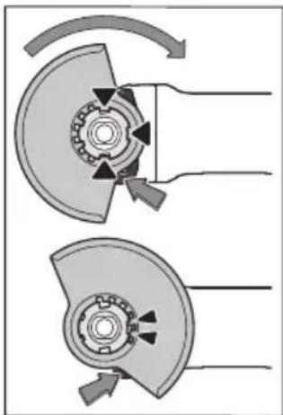
Jg.10) aIJI 111 (1) 111 (2) JI (1) 111 (2) JI (10) aIJI I I (10) aIJI I I (10) aIJI I I (10) aIJI I I (10) aIJI I I (10) aIJI I I (10) aIJI I I (10) aIJI I I (10) aIJI I I (10) aIJI I I (10) aIJI I I (10) aIJI I I
.1uJl
aLgIbIe aIyI IIOI Jn oJ: Lw!
oJyIaLgIbIe BcBjSjAilso! (10)
.Boq ayUyJ
gbl yIaLgIbIe
yIaLgIbIe IbcIe IcIe IyI
gblgabawggbllsicgbll
.(13) abjol
sic aIgIs Ibc baw jegj gglr
.aaJIgJg
(13) g bll y aaggl lbc c bys p
.(10) g ll y aaggl lbc c bys sb
(24) d gill jy go ball bawl lbc c bys p
(10)
f! 1
Jg 20 9 1
(9) fLx
Jgll aB (9) fLx Jg 1
. wglw g
guiuui Uuiuip 500 gao daigaiu I uuc
:abgalo.
Jn Jn Jn Jn Jn Jn Jn Jn Jn Jn Jn Jn Jn Jn Jn Jn Jn Jn Jn Jn Jn Jn Jn Jn Jn Jn Jn Jn Jn Jn Jn Jn Jn Jn Jn Jn Jn Jn Jn Jn Jn Jn Jn Jn Jn Jn Jn Jn Jn Jn Jn
g p g uu U g i j w j n k
y 8. duiu o jn u j n j g , g
p Jj J J J J J J J J J J J J J J J J J J J J J J J J J J J J J J J J J J J J J J J J J J J J J J J J J J J J J J J J J J JJ
"Electro1
LalbIg
.1J LkW b uuuiuauu uuuu uuuu uuuu uuuu uuuu uuuu uuuu uuuu uuuu uuuu uuuu uuuu uuuu uuuu uuuu uuuu uuuu uuuu uuuu uuuu uuuu uuuu uuuu uuuu uuuu uuuu uuuu uuuu uuuu uuuu uuuu uuuu uuuu uuu uuuu uuuu uuuu uuuu uuuu uuuu uuuu uuuu uuuu uuuu uuuu uuuu uuuu uuuu uuuu uuuu uuuu uuuu uuuu uuuu uuuu uuuu uuuu uuuu uuuu uuuu uuuu uuuu uuuu uuuu uuuu uuuu uuuu uu
pSjJI Eji
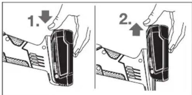
6(1la. 0o jgaa
JU 1
JU 5(2)labg Uusuill4(g
gogpJnaw aLa Ungo Jolku
| % 66 ≤ | \( \% \) |
| % 66 -33 | \( \% \) |
| % 33-11 | \( \% \) |
| % 10 ≥ | \( \% \) |
aIJ
Jl JIJI JIJI JIJI JIJI JIJI JIJI JIJI JIJI JIJI JIJI JIJI JIJI JIJI JIJI JIJI JIJI JIJI JIJI JIJI JIJI JIJI JIJI JIJI JIJI JIJI JIJI JIJI JIJI JIJI JIJI JIJI JIJI JIJI JIJI
Cwjjjbc
(2)UJgUJG
UJgUO
algoaI J.
16(duoJW
Wgall Ueuaa
uJyJW algoa
aJyJW algoa
olJgogab
aclll UJLc aJ
Upg jds
Wgall Ueuaa
swJyJW algoa
CooJow!
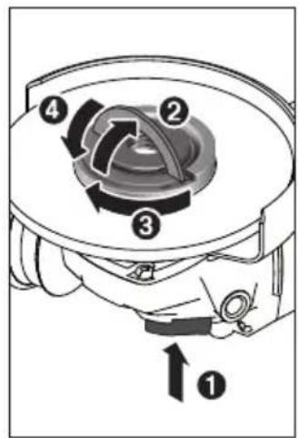
J 8
algoaIgaiSao aulluul uall aegw
paw Jsw abgjoll uysyolal.ug
wagll elaaolglj
swll adew algoaI
adew algoaJlg
oJL WSCogoswll X.aclwl UJac
Gssc I psoaW
aeew algoaIg
oasiaI sUll
bJI gao pddwlg .wJLL
aui jy jy /jg u g uu 1 y b g u g u g u g u u u u u u u u u u u u u u u u u u u u u u u u u u u u u u u u u u u uu
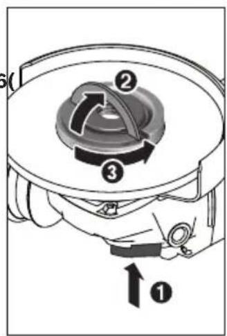
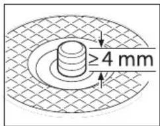
.aaJgSJI oJJI JgJI
gio aal) jy kj p 11) aai (uui i 10a jaiia 10i y i gai y i
山山山g 1s s 4
aIg pUw Uk uu Ud Uc uu u
Ukai ooc no ss. aJ gJgJgK
JjA no Ioo gglagb JgJg
Jusll Jc laI sull aelg uKjui
(18) uJu JU 0J pJ aWJ
IbIbIbIbIbIbIbIbIbIbIbIbIbIbIbIbIbIbIbIbIbIbIbIbIbIbIbIbIbIbIbIbIbIbIbIbIbIbIbIbIbIbIbIbIbIbIbIbIbIbI bII (19)
(18)laiaaiaaaiaaaiaaaiaaaiaaaiaaaiaaaiaaaiaaaiaaaiaaaiaaaiaaaiaaaiaaaiaaaiaaaiaaaiaaaiaaaiaaaiaaaiaaaiaaaiaaaiaaaiaaaiaaaiaaaiaaaiaaaiaaaiaaaiaaaiaaaiaaaiaaaiaaaiaaaiaaaiaaaiaaaiaaaiaaaiaaaiaaaiaaaiaaaiaaaiaaaiaaaa
Jljjll lI I
Vibration Control
1 liu y jy 11111111111111111111111111111111
.1JU 1 JI 1JL 1JLg
www.bosch-pt.com/serviceaddresses
Jai
gilq kAs aySall guyll Uig! pslg aasj
Jai npaa j Pssuall Gaa.0hblsla gall
bgw ayb ssll ugs lglal Lc pslal
aI
JnJnJnJnJnJnJnJnJnJnJnJnJnJnJnJnJnJnJnJnJnJnJnJnJnJnJnJnJnJnJnJnJnJnJnJnJnJnJnJnJnJnJnJnJnJnJnJnJnJnJ.
aJyjSll o sL Jn j
aJbIgSdS JI aI I aI gIgIg aI I aI I aI I aI I aI I aI I aI I aI I aI I aI I aI I aI I aI I aI I aI I aI I aI I aI I aI I aI I aI I aI I aI I aI I aI I aI I aI I aI I aI I aI I aI I aI I aI I aI I
/psjglg auiuajl jll 1auii laiil juii

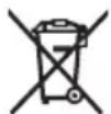
gX1 Jx1 Jx1 b
gjg jqg2012/19/EU
g g g g g g g g g g g g g g g g g g g g g g g g g g g g g g g g g g g g g g g g g g g g g g g g g g g g
:UJUJI/0sIJIJI
:oguU Ugul oSIjo
jll) jll jg oJgll 1sIwJyolclj y .(314 aonll,“Jaiil,
g jg g bll aLac lqj y g dJlO o g dJc acjw JaaU g g Uc Joo wolglb
joo
Jg 1Kw gagol Jsw jg
g 110a c g yb jc l d w sle! jSog. aalj Jlll IuW Lc, bJol oIola g
.
aJw! 1sJw!
LgJgJgJgJgJgJgJgJgJgJgJgJgJgJgJgJgJgJgJgJgJgJgJgJgJgJgJgJgJgJgJgJgJgJgJgJgJgJgJgJgJgJgJgJgJgJgJgJgJgJg
JUaJI Jg. gU U 0 g U g Ug Ug JaJI Ug gUJI Ug WUJI Ug SuaJI OJUuUJ Ug wUJI liU J do gI JlaUJI
aJoo aoo jol alol oJl
.1aJg aBjll j0 aSjall aLaa
0o oJd aJg lbi g 9 JpJj joo -
Jiau Jnq
oJs aJy JnJnJnJnJnJnJnJnJnJnJnJnJnJnJnJnJnJnJnJnJnJnJnJnJnJnJnJnJnJnJnJnJnJnJnJnJnJnJnJnJnJn
y dgl uowl 9 pJol J i j 1 .dU w
.5dall jyalll saa lalall gclj
ddJg dJll
山
aJlalll) aJIyIgIL JIeJI gI Iqai jLg (..gJg
Laijaibc
Jgao JUSSuBglg uou
aIbIaJolg JkW Joaal L
.uggul lao g uJgSJI oJl alu
.ullgologglu jy
pIddwI IJlWwIg 1do
a aalaii iaiwla Jaojdo jy jy y gwl j. jglgab adloxy, duiug jll l jglblagb ayolll ologlall
:golww.b
Bosch
lulua 0gaaa bJluoaiw |s| k|k|d
.lglalog
aagll aog jusll lilg caioll pj s jy ju 1uulb g i jluoow auiuwsic qiaollg
Jucg
J
Robert Bosch Morocco SARL
53g
20300L
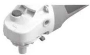
2605703014
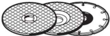
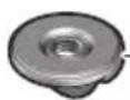
1600AO16DN
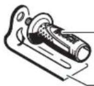
2602025183
2609006332
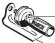
1601329013
2602025182
1601329013
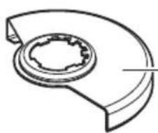
0115mm
2605510288
0125mm
2605510289
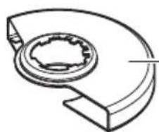
0115mm
2605510290
0125mm
2605510291
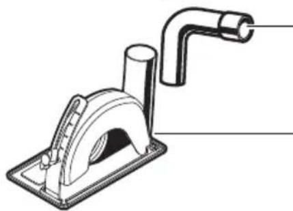
0 115/125 mm
1600793007
2605510292
Licenses
Copyright © 2015, Infineon Technologies AG
All rights reserved.
Redistribution and use in source and binary forms, with or without modification, are permitted provided that the following conditions are met:
- Redistributions of source code must retain the above copyright notice, this list of conditions and the following disclaimer.
- Redistributions in binary form must reproduce the above copyright notice, this list of conditions and the following disclaimer in the documentation and/or other materials provided with the distribution.
- Neither the name of the copyright holders nor the names of its contributors may be used to endorse or promote products derived from this software without specific prior written permission.
THIS SOFTWARE IS PROVIDED BY THE COPYRIGHT HOLDERS AND COLNTRutors "AS IS" AND ANY EXPRESS OR IMPLIED WARRANTY, INCLUDING, BUT NOT LIMITED TO, THE IMPLIED WARRANTY OF MERCHANTABILITY AND FITNESS FOR A PARTICULAR PURPOSE ARE DISCLAIMED. IN NO EVENT SHALL THE COPYRIGHT OWNER OR COLNTRutors BE LIABLE FOR ANY DIRECT, INDIRECT, INCIDENTAL, SPECIAL, EXEMPLARY, OR CONSEQUENTIAL DAMAGES (INCLUDING, BUT NOT LIMITED TO, PROCEDURE OF SUBSTITUTE GOODS OR SERVICES; LOSS OF USE, DATA, OR PROFITS; OR BUSINESS INTER-RUPTION) HOWEVER CAUSED AND ON ANY THEORY OF LIABILITY, WHETHER IN CONTRACT, STRICT LIABILITY, OR TORT (IN-CLUDING NEGLIGENCE OR OTHERWISE) ARISING IN ANY WAY OUT OF THE USE OF THIS SOFTWARE, EVEN IF ADVISED OF THE POSSIBILITY OF SUCH DAMAGE.
| € | ||
| de | EU-Konformitätserklärung | |
| Winkelschleifer | Sachnummer | |
| en | EU Declaration of Conformity | |
| Angle grinder | Article number | |
| fr | Déclaration de conformité UE | |
| Meuleuse d'angle | N° d'article | |
| es | Declaración de conformidad UE | |
| Amoladora angular | No de articulo | |
| pt | Déclaración de Conformidade UE | |
| Rebarbadora | N.° do produits | |
| it | Dichiarazione di conformità UE | |
| Smerigliatrice angolare | Codice prodotto | |
| nl | EU-conformiteitsverklaring | |
| Haakse slijpmachine | Productnumber | |
| da | EU-overensstammelseserklaering | |
| Vinkelsliber | Typenummer | |
| sv | EU-konformitetsförklaring | |
| Vinkelslip | Produktnummer | |
| no | EU-samsvarserklaering | |
| Vinkelslipper | Produktnummer | |
| fi | EU-vaatimustemnukaisuusvakuutus | |
| Kulmahiomakone | Tuotenumero | |
| el | Δηλωση ποτόπτας EE | |
| Γωνιακός Αριθμός ευρετηρίου | Δηλώνουμε με απολειούνης εμας ευθύνη, στήτα τιαναφερόμενα προίντα | |
| λειαντήρας | ||
| tr | AB Uygunluk beyan | |
| Taşlama makinesi | Urün kodu | |
| II | |||
| pl | Deklaracja zgodnosci UE | Oświadczamy z pełna odpowiedzialnosci, ze ninejsze produkty odpowiadaj wzystkim wymaganiom poniżej wyszczególionych dyrektyw i Rozporzadzeń, oraz ze są zgodne z nastepujacymi normami. Dokumentacja techniczna:* | |
| Szilifierka kątowa Numer katalogowy | |||
| cs | EU prohlášeni oshodě | Prohlášujeme na vyhradni zodpovednost, ze uvedený vyrobek splůje věsechna príslužná ustanoveni niže uvedenych směrnic anarizení ale vsouladu snásledujícimi normami: Technické podklady u:* | |
| Uhlová bruska ObjednaciCIDSO | Vyhlasujeme na vyhradnu zodpovednost, ze uvedený vyrobek splína věsteky prislužné ustanovenia nižsie uvedenych smernic anariadení ale vsulade snásledujúcimi normami: Technické podklady má spolocnost:* | ||
| sk | EU vyhlásenie ozhode | Egyedūl feleloşegg kijelentjuk, hogy a megnevezett termékem megfelelnek az alábbiakban felsorolársa keruló irányelvek és rendeteck valamennyi idevágó elöirásainak és megfelelnek a kõvetkező szabványoknak. Mûszaki dokumentumok megörzési pontja:* | |
| Uhlová brúská VecnéCIDSO | 3aJbIeHne O COOTBETCTBNI EC | ||
| Sarokcsiszoló Cikkszám | Mlb 3aJbIeHem pod nau shу edinHOnLIHyU O TBETCTBENHOCTb,чTo Na3BaHNbIeПрodyKtBu COOTBETCTBYIOT BcEM DeIcTBYIOUIM PrédINCAHNIM HIXKeyUa3AHbIX DINOPEKTHB IN PACNORJKeHIn, a TAKJE HIXKeyUa3AHbIX HOPM. TexNHueckay DOKUMENTAÇU XPAHNTCBy:* | ||
| ru | 3aJbIeHne O COOTBETCTBNI EC | Mlb 3aJbIeHem pod nau shу edinHOnLIHyU O TBETCTBENHOCTb,чTo Na3BaHNbIeПрodyKtBu COOTBETCTBYIOT BcEM DeIcTBYIOUIM PrédINCAHNIM HIXKeyUa3AHbIX DINOPEKTHB IN POCNORJKeHIn, a TAKJE HIXKeyUa3AHbIX HOPM. TexNHueckay DOKUMENTAÇU 36EBIaTcBcY:* | |
| UhlOBa Tobilny NQ | 3aJbIeHne O PID nau shу edinHOnLIHyU O TBETCTBENHOCTb,чTo Na3BaHNbIeВIOBIIDAOITb YCIM ChINHNIM PONOKENHIM HINUeO3NaHcHIN DINOPEKTHB IN POCNORJKeHIn, a TAKJE HIXKeyUa3AHbIX HOPM. TexNHueckay DOKUMENTAÇU 36EBIaTcBcY:* | ||
| шлфовальнай�а Maшина | 3aJbIeHne O PID nau shу edinHOnLIHyU O TBETCTBENHOCTb,чTo Na3BaHNbIeВIOBIIDAOITb YCIM ChINHNIM PONOKENHIM HINUeO3NaHcHIN DINOPEKTHB IN POCNORJKeHIn, a TAKJE HIXKeyUa3AHBIX HOPM. | ||
| uk | 3aJbIeHne O COOTBETCTBNI EC | Mlb 3aJbIeHem pod nau shу edinHOnLIHyU O TBETCTBENHOCTb,чTo Na3BaHNbIeВIOBIIDAOITb YCIM ChINHNIM PONOKENHIM HINUeO3NaHcHIN DINOPEKTHB IN POCNORJKeHIn, a TAKJE HIXKeyUa3AHbIX HOPM. | |
| Kytobla Tobilny Homep | 3aJbIeHne O PID nau shу edinHOnLIHyU O TBETCTBENHOCTb,чTo Na3BaHNbIeВIOBIIDAOITb YCIM ChINHNIM PONOKENHIM HINUeO3NaHcHIN DINOPEKTHB IN POCNORJKeHIn, a TAKJE HIXKeyUa3AHhIX HOPM. | ||
| шлфовальнai Maшина | 3aJbIeHne O PID nau shу edinHOnLIHyU O TBETCTBENHOCTb,чTo Na3BaHNbIeВIOBIIDAOITb YCIM ChINHNIM PONOKENHIN HINUeO3NaHcHIN DINOPEKTHB IN POCNORJKeHIn, a TAKJE HIXKeyUa3AHbIX HOPM. | ||
| kk | EO cαJbIeTik MaflymdamacbI | 3aJbIeHne O PID nau shу edinHOnLIHyU O TBETCTBENHOCTb,чTo Na3BaHNbIePrOJIcRrTeJx J3bIqFAn | |
| Бурьtsык Tobilka БИм Немір | ДиЯалперштійКЕн БИЗ ATALFAN EнIMДER TOMЕДж КЗБИФAN | ||
| Жарлай Maшинсы | ДиЯалперштійМел МEL KOMIAPANМEL KOMIAPAN, a TAKJE HIXKeyUa3AHbIX HOPM. | ||
| ro | Declaratağte de conformitate UE | Declarãm pe proprie râspundere cà produselementionate corespund tuturor dispoziților relevante ale directivelor ŞI reglementăriler enumerate in cele ce urmează ŞI sunt òn conformitate cu următoarele standarde. Documentatie tehnica'la:* | |
| Polizor unghiular Numār de identificare | Documentatie tehnica'la:* | ||
| bg | EC dɛknapaίя 3a cθbTETCTBNI | C Пьліноэ оTOвОвPORTСНе ДЕКларпаме, чTwoоночЕнite РождУТСНоTROВАРгет на BCNUKИВалДИН ИЗСКВаньпа на ДИрЕКТВИТЕ и рAZПорopedБITEпо-ДOLу и сθbTETCTBA на СLEДНITE CTANДAPТи. | |
| БtrLOшалф | 3aJbIeHne O PID nau shу edinHOnLIHyU O TBETCTBENHOCTb,чTo Na3BaHNbIeВIOBIIDAOITb YCIM ChINHNIM PONOKENHIN HINUeO3NaHcHIN DINOPEKTHB IN POCNORJKeHIn, a TAKJE HIXKeyUa3AHBIX HOPM. | ||
| mk | EU-H3jaba 3a coo6ba7enosti | Coцелоча оTOвОвPORTСНе ДИЛавуВаме,.Deca оПишанite РождВОдсce Bo corlaçncHTC no CHTe peLecVAHNTHи OdopeĐине на СLEДНITE perγιλatNBи и РождСинсу CBNUKИВалДИН ИЗСКВаньпа на ДИрЕКТВИТЕ и рAZПорopedБITEпо-ДOLу и сθbTETCTBA на СLEДНITE CTANДAPТи. | |
| Агona 6brucnilka | 3aJbIeHne O PID nau shу edinHOnLIHyU O TBETCTBENHOCTb,чTo Na3BaHNbIePrOJIcRrTeJx J3bIqFAn | ||
| sr | EU-izjava o usaglašenosti | Na sopstvenu odgovornost izjavljemo, da navedeni proizvodi odgovaraju svim dotovičnim odredbama naknadno navedenih smernica u uredaba i da su skladu sa sledećim standardima. | |
| Ugaona brusilica Broj predmeta | 3aJbIeHne O PID nau shу edinHOnLIHyU O TBETCTBENHOCTb,чTo Na3BaHNbIePrOJIcRrTeJx J3bIqFAn | ||
| sl | Izjava o skladnosti EU | Izjavljamo pod izključno odgovornostjo, da je omenjen izdelek v skladu z | |
| Kotni brusilnik Številka artikla | 3aJbIeHne O PID nau shу edinHOnLIHyU O TBETCTBENHOCTb,чTo Na3BaHNbIePrOJIcRrTeJx J3bIqFAn | ||
| hr | EU izjava o skladnosti | Pod punom odgovornošću izjavljemo da navedeni proizvodi odgovaraju svim relevantim odredbama direktiva i propisima navedenima u nastavku i da su skladn di sljedecim normama. | |
| Kutna brusilica Kataloški br. | 3aJbIeHne O PID nau shу edinHOnLIHyU O TBETCTBENHOCTb,чTo Na3BaHNbIePrOJIcRrTeJx J3bIqFAn | ||
| CE | III | ||
| et | EL-vastavusdeklaratsioon | Kinnitame ainuvastutajatena, et nimetakud tooted vastavad järgnevalt loetletud direktiivide ja määruste köikidele asjaomastele nõuetele ja on kooskõlas järgmiste normidega. Tehnilsed dokumendid saadaval:* | |
| Nurklihvmasin Tootenumber | |||
| lv | Deklarăcija par atbilstibu ES standartiem | Mës ar pilnu atbildibu pazinojam, ka šeit aplūkotie izstrādăjumi atbilst visiem tālak minētajās direktivās un rikojumos ietvertajām saistōsajām nostădnēm, kā ari sekojošiem standartiem. Tehniskā Dokumentăcija no:* | |
| Lenka slipmašina Izstrādăjuma numurs | |||
| lt | ES atitikties deklaracijs | Atsakingai pareiškiame, kad išvardyti gaminiai atitinka visus privalomus Žemiau nurodytu direktvyūr reglamenti reikalavimus ir šiuos standartus. Techné Dokumentăcija saugoma:* | |
| Kampinio Gaminio numeris šilifavimo mašina | |||
| 18 | AdvancedGrind 3 603 CD9 0.. | 2006/42/EC EN 60745-1:2009+A11:20102014/30/EU EN 60745-2-3:2011+A2:2013+2011/65/EU A11:2014+A12:2014+A13:2015EN 55014-1:2017+A11:2020EN 55014-2:2015EN IEC 63000:2018 | |
| BOSCH * Robert Bosch Power Tools GmbH (PT/ECS)70538 StuttgartGERMANY | |||
| Henk BeckerHelmut HeinzelmannChairman of ExecutiveHead of Product CertificationManagement | |||
| Robert Bosch Power Tools GmbH, 70538 Stuttgart, GERMANYStuttgart, 22.03.2021 | |||
Declaration of Conformity
Angle grinder Article number
AdvancedGrind 183603 CD9001
We declare under our sole responsibility that the stated products comply with all applicable provisions of the regulations listed below and are in conformity with the following standards.
Technical file at: Robert Bosch Ltd. (PT/SOP-GB), Broadwater Park, North Orbital Road, Uxbridge UB9 5HJ, United Kingdom
The Supply of Machinery (Safety) Regulations 2008
The Electromagnetic Compatibility Regulations 2016
The Restriction of the Use of Certain Hazardous Substances in
Electrical and Electronic Equipment Regulations 2012
EN 60745-1:2009+A11:2010
EN 60745-2-3:2011+A2:2013+A11:2014+
A12:2014+A13:2015
EN 55014-1:2017+A11:2020
EN 55014-2:2015
ENIEC63000:2018

BOSCH
Robert Bosch Power Tools GmbH, 70538 Stuttgart, Germany represented (in terms of the above regulations) by
Robert Bosch Limited, Broadwater Park, North Orbital Road,
Uxbridge UB9 5HJ, United Kingdom
Vonjy Rajakoba
Managing Director - Bosch UK

Martin Sibley
Head of Sales Operations and Aftersales

Robert Bosch Ltd. Broadwater Park, North Orbital Road, Uxbridge UB9 5HJ, United Kingdom, as authorised representative acting on behalf of Robert Bosch Power Tools GmbH, 70538 Stuttgart, Germany
Place of issue: Uxbridge Date of issue: 28/04/2021


- Transport
- General Power Tool SafetyWarnings
- WARNING
- Save all warnings and instructions for future reference.
- Work area safety
- Electrical safety
- Personal safety
- Power tool use and care
- Battery tool use and care
- Service
- SafetyWarnings for AngleGrinder
- SafetyWarnings common for Grinding, Sanding,Wire Brushing or Abrasive Cutting Off operations
- Kickback and RelatedWarnings
- SafetyWarnings specific for Grinding and Abrasive Cutting-Off operations
- Additional SafetyWarnings specific for Abrasive Cutting Off operations
- SafetyWarnings specific for Sanding operations
- SafetyWarnings specific for Wire Brushing operations
- Additional safety information
- Product Description and Specifications
- Intended use
- Product Features
- Technical Data
- Noise/Vibration Information
- EN 60745-2-3.
- Wear hearing protection!
- Fitting
- Charging the battery
- Removing the battery
- Charge-control Indicator
- Fitting Protective Equipment
- Protective guard for grinding
- Protective guard for cutting
- Extraction guard for cutting with a guide block
- Side handle
- Low-vibration auxiliary handle
- Do not continue to use a damaged auxiliary handle.
- Hand guard
- Fitting the Abrasive Tools
- Grinding/Cutting Disc
- Flap disc
- Rubber Sanding Pad
- Cup brush/disc brush
- Carbide Grinding Head
- Approved abrasive tools
- Dust/Chip Extraction
- Operation
- Starting Operation
- Inserting the battery
- Switching on/off
- Restart protection
- Constant Electronic control
- Soft start
- Speed preselection
- Practical advice
- Rough grinding
- Cutting metal
- Cutting Stone (see figure A)
- Information on structural design
- Recommendations for optimal handling of the battery
- Maintenance and Service
- Maintenance and Cleaning
- To ensure safe and efficient operation, always keep the power tool and the ventilation slots clean.
- After-Sales Service and Application Service
- Great Britain
- You can find further service addresses at:
- Disposal
- Only for EU countries:
- Only for United Kingdom
- Battery packs/batteries:
- Français
- Protection anti-redemarrage
- Transporte
- Montar as ferramentas de lixar
- Trasporto
- Vervoer
- Du hittar fler kontaktuppgifter till service har:
- Vernedeksel for sliping
- Kuljetus
- Metaφορα
- Anóoupon
- Móvo yua xωpeç tnc EE:
- Canakfirca/diskfirca
- Nakliye
- System Constant Electronic
- Přeprava
- Szallitas
- CneunabhbIe npedynpentenbHbIe yka3aHnIa InnfoBaHHn HkDaUHO 6ymarO
- Oc06bI npEduynpeDnteHbIe yka3aHnI da pa6oT c npOBOnouHbIMN uetKaMn
- DOnONHtEnbHbIe yka3aHaH No TEXHNke 6e30NaCHOCTN
- Oncsahne npodukta uycny
- PnmeHne Hn Ha3HaueHnIO
- 1306paXeHHbIe cocTaBHbIe qactn
- DaHbIe no Wymy n Bn6paun
- HcnoIb3yIte cpeIcTBa 3aunTbI opraHOB cnyxa!
- C6opka
- 3apkaakkymyTopa
- HdHKaTop 3apXeHHoCTn
- MOHTAX 3aunTHbIX yctpoiCTB
- 3aunthbik KoxyDnI uHOBAHNA
- 3aunthbikkoxydnpe3KN
- 3aunthbikoxkuyx dny pe3KN c hnpabnloumm cana3kamh
- DononHntenbHa pyKoRTKa
- Bn6poracaaan dononHntenbna pykoRTka
- 3aunTHbI uHTOK pykn
- MoHTax ⅢnfoBaIbHoi OchactKu
- UHHFOBaHbHbI Kpyr/OTpe3HOKpyr
- BeehbiwnfoBaNbblkpyr
- Pe3HHOBaI WlnfoBaIbHaI TapeIka
- UaewuHaJtKa/DnCKOBaJtKa
- TBePdoCnBbIyaaeHbIyIINfoBaIbHbI Kpyr
- DonyctmnaaunfoBaanbHaOchactka
- YdaeneHne bInn n ctpyKKn
- Pa6ota c nHcTpymeHTOM
- Bknouehne 3nEkpHcTpymenta
- YcTaHOBka aKKymyTopa
- BknIOueHne/BBKIOueHne
- 3aunra ot HenpehamepeHHoro nycka
- KoHCTaHTHa 3NeKtpOnnka
- PnaBbIy nck
- Bb6op uncna 06oPoTOB
- Pe3ka Metanna
- Pe3ka kAMHr (cm.phc.A)
- Yka3aHnnoCTaTHKe
- Yka3aHnno ONTmambHomy 6paueHnIO c aKKymyIATOPOM
- TexobnyxmbaHne n cepBnC
- Texo6cnyxHBaHne n ouhctka
- CepBnC n KOncyIbTnpOBaHne no BOpocam npMmHeHH
- ДлpernoHa:Pocchya,Benapycb,Ka3axCTan,YkpanHa
- Pocchra
- DononHntenbHbIe aDpeca cepBnCHbIX ueHTpOB Bbl HaJeTe No CcbInke:
- TpaHcnpTpObKa
- Ytlln3aun
- ToIbko dny cTpaH-ueHOB EC:
- AkkymyIaTOpbl/6aTapeH:
- JIHTHINHOHHbIe:
- YkpaIHcbka
- Bka3iBkn 3 texhikn 6e3nekn
- 3araIbHI 3aTepeXeHHnIe nEeKTPoPnIaIb
- NONEPE-IXKEHNA
- I06pe 36epiraTe Ha Maib6yTHe ci nonepeJxHnHa i BkazIBKn.
- MONTAX
- 3apxkHnAkyMnyTOpHo6aTapei
- IHHKAtop3apAKeHocTi
- 3axnCTdnypykn
- MoHTaX WniciyBaIbHnx po6oHx iHcTpymeHtIB
- UliyBaIbHn/BiPi3Hn Kpyr
- BiaIonoi6HnI uIiOyBaIbHn Kpyr
- Tymobn tapinactn wniifybalbnn kpyr
- UaikOBA/ДИСКОВA uITKa
- TbePdoCnabHn qaIKOBn dNCK
- D03B0neHi wniifyBaIbhi iHcTpymeHTn
- BicmOKTyBaHHnHy/Tnpch/ctpyxKn
- Po6ota
- PouaToK po6OtN
- BctpomnHHa akymnatopHO6atapei
- BMKaHHBmKahH
- 3axnCT BiN NOBTOPOIycky
- NocriHa eIeKtrponika
- PnabHnn nyck
- BctahOBJENHKnIbKocti 06epTIB
- Bianonoadi6nuiybalhnykpyr
- Pozpi3aHHMeTany
- P03pi3aHHKaMeHIO (nVB.MaI.A)
- Bka3iBkn 0oDo cTaTnKn
- Bka3iBKn 0oOOnTmAbhHOro NOBODKeHHa akymyIATOpom
- Texhuihe 06cnyroByBaHHaicepBic
- Texhiue 06cnyroByBaHH i ouuueHH
- Cepbic KOHCyNbTauii 3nHTaHb 3actocyBaHHA
- YkpaHa
- Adepcnihnx cepbichnx ceHTpiHabeedeHO Hxue:
- TpaHcnpTyBaHHa
- Ytuniauia
- Jnue nKpaH EC:
- Akymnyatopn/6aTapeien:
- JitieBO-ioHHI:
- Ka3ak
- Eypa3nЯ ekOHOMNKaIbIK OdafbiHa (Keeden OdafbiHa) Mywe MemlekeTepayMaftbIHda
- KoIdaHbInaIbI
- Thimi nai danany Mep3imi
- ICTEHwbyfce6entepinHti3iM
- PaiDanaHybIbH, MymKIn KaTeiKTepi
- Wektky6enrinepi
- KbI3MeT Kepcety Typi MeH xiniriri
- CaKray
- Tacbimanay
- Kayinci3dk HycKaynapbl
- Kannbl 3nektp kypandbi kayinci3dk HycKaynapbl
- ECKEPTY
- Bapnbik kayinci3dknyckaynbikTapbIH XaHe
- Bonaawk kymbictap yuih kayinciik hycaynbiktapbi Me h ckeptnenepei caKan Koibih3.
- XymbicophbiHbIHkayinci3di
- 3neKtpKayincizdiri
- KekeKayinci3ik
- 3neKtp KypanapbH naiDanaHy XaHe KyTy
- Batape KypanbH naiDanaHy XaHe Kyry
- KbI3MeT Kepcety
- BypbIbTkTericTey MaunHapbH naJaAnaHy Ke3iHderi Kayinci3dk TexnKacbl
- KaITapbIM MeH Tnicti eckepTnepep
- MaДанану MeH a6pa3nBti Kecyre apHaNFaH Kayinci3dik HycKaynapbl
- A6pa3nBtI Kecyre aphanraH KocbIMwa Kayinci3dk HycKaynapbl
- Akapnay opekeTepi yuin kayinc3dk hycKaynapbl
- CbIM KbluBikneh Ta3anay opeKeTepi yuiH Kayinci3dk HycKaynapbl
- Kocbimwa kayinci3dk HycKaynbikTapbi
- Ohim xhe KyaT cHaTaMaCbl
- TaFauBHdany 6oBbHwa konDaHy
- Бeненгн КурмбI 6иштep
- BypbIHTbIK axapnay MaunHaCbl
- AdvancedGrind 18
- UybIn KHe DipinDey TpaNbI aKnapaT
- Kynaktbkopray KypandapbH KnniH3!
- XnHay
- AkkymyTopdbi 3apdTay
- AkkymyIaTOpdbIweu
- 3apd deHreinHnHdkaTOpbl
- XapbIKnOdbI Kyatbl
- KopfahbIw acnantbl opHaty
- Tericetyre aphanfah Koprafbii KanTama
- Terictey wen6epi/kecy wen6epi
- XennyiT api3i T erictey weh6epi
- Pe3eHKe tericTey rapeNkeci
- ToctaraH Tepi3di Kblwblk/duckkinKblwblk
- KattbikopbirtnaTOCTaFAn TApia3i terictey weH6epi
- Kapamdb tericTre kypaib
- UahdbjXeHe KOHkanaIapbI copy
- PaindanaHy
- Painanahyfa eHipy
- Akkymyntopdbi ophaTy
- Kocy/ewipy
- Kaeta Ko3rany caKtaBliWbl
- TypaKtbl 3neKtpoHnka
- Bipkanbintbi icke kocy
- AHHany xhiinirih andbih ana taHday tetiri
- Painanany Hycaynapbi
- CbIdbipbn terictey
- Xennyiw Taipizi Terictey weh6epi
- Metanapdbkecy
- Tactbkecy(A cypetin kapaHbi3)
- CtAtnKa Tpyanbl HycKaynap
- AkkymyIopDbIOHTaINbI naHdanaHy typabI hyckaynap
- TexHnKaIbIK Kytim XaHe KbI3MeT
- KbI3MeT KepceTy XaHe Ta3anay
- TytbHybifa KbI3MeT KOpCety XaHe naJaIaNHy KeHecTepi
- nPMAblk Hemece aBTopn3aunraHaHaN Kb3MeT KepCteTy optaBlkTaBPbHdaOpbHdaIaDbE. ECKEPT! 3aHcb3XoJlmEH eKeiHReh OHIMdepdi NaJaIaNHy Kayinti, DeHCayNbIFbIHbI3Fa 3nH KeNTipy MyMkiH. OHIMdepdi 3aHcb3Kacay XaHe Tapaty Akimuiik XaHe KbIMbcTBk TApTIn 60bIHwa 3aHmeh KydanaHaDbI.
- Ka3akctah
- KbI3MeT Kepcety opTaNbIKTapbIHbN 6acka da MeKeHxaiJapbIH MbiHa JepdEe KapaHbI3:
- Kadere kapaty
- TekKaHaEOeepi yuin:
- AkkymyIaTOpnap/6aTapeIaNap:
- JIHTHm-HoHdbik:
- Româna
- Instruktiuni de siguranta
- Sistem electronic constant
- Pornire lenta
- OTkATnCBbp3HN npdeynpejxdeHNA
- IpeynpekdeHna 3a6e3oNaHcOCT, cneuΦnHn 3a deHocTH no uHΦoBaHe n a6pa3NBHO p3aHe
- DonbHnTeHH yka3aHH 3a 6e3oNaChocT, cneuHnH 3a a6pa3HBHO p3aHe
- Cneunuyn yka3aann 3a 6e3onacnoct npn uHnfoBaHe
- Cneunuynyka3aHna 3a6e3oNaChoc npn pa6oTa c TeneHH ueTKN
- DonbHHTenHH yka3aHHa 3a6e3oNaCHOCT
- OnncahneHa npoduktaNdeHocCTTa
- PpeHa3NaueHne Ha eNeKtpoHcTpymeHt
- H306pa3eHH enemeHTN
- 3apeKdaHe Ha akymylaTopHaTa 6aTepeH
- I3BaXdane Ha akymylatopHaTa 6aTepeH
- HdNkaTop 3a cTeNeHTa Ha 3apeDeHoCT Ha akymynaTopHaTa 6aTepnA
- CbeToaNoKanaunTeT
- MOnTnpaHe Ha 3aunTHo cbOpbXeHne
- PpeNa3eKoKx3aWlnfoBaHe
- PpeIpa3eH Koxy 3a p3aHe
- Ppaxon3cMyKbau KoKyx 3a pR3aHe C BOeua WeHa
- CnomarateenHa pbkoxBaTka
- Bb6ponornbuaa cnoMaratenna pbkoxBatka
- Vibration
- 3aunta 3a pbue
- MOnTnpaHe Ha ⅢnHΦoBaunHnHCTpyMeHT
- Dnck3a wlnfoBahe/pra3ane
- Betpnoo6pa3eH nlaactnHcT dNck
- Tymennojnoxekn
- aawkoBnHa TeeneHa YetKa/tnckoBa YetKa
- Tbbpocnbaencauskobndenck
- Pa3peweHHNCTpyMeHTn 3a WnHΦoBaHe
- CnCTema 3a npaxoynahe
- Pabota c eleektpoHHcTpymenta
- Nyskahe BekcnnoaTaH
- NoctabnHe Ha akymyataophata 6aTepeH
- BknIOUbaHe n H3KIOUbaHe
- 3aunita cpeuy nobtopHO BKIOUbaHe
- MóyI 3a noctoHHa ckopoCT Ha BbptHe
- Плавно BКЛIOчBAнe
- PpeBapnteneH36OpHaCKopoCtTaHa BbptHe
- Yka3aHnHa 3a pa6oTa
- Tpy6o wnnfoBaHe
- Betpnnoo6pa3eH nnaCTnHaT dNck
- PraHa He MaTea
- P3aHe Ha KambK (Bx. qHr. A)
- Yka3aHnHa 3a CTAHTKaTa
- Yka3aHn3a ONTmAlHo 6opabeHe cakymnaTopHaTa 6atepna
- PoiDbpxKaHe n cepBn3
- IopdbpxkHe n nouchTahe
- KlneHTcKa cnyX6a n KOHCyntaunr OTHOCHOynotpe6ata
- www.bosch-pt.com
- Блгария
- Дргн сервзндадесн оТкпене на:
- TpaHcnopTnpaHe
- БракуВанe
- Cama 3a ctpaan ot EC:
- AkymnyatopHH Hn 6nKHOBeHH 6aTeepHn:
- JIHTHEBO-NOHHN:
- MaKeDoHcKn
- БeЗб endocnн HanomeHn
- OnuTn npedynpeyBaBa 3a 6e36eHocT ha eNeKtpnHn aHaTu
- PENEy
- PENEYBAHbE
- 3auybajTe r6e36eHNOCHHTpepynpedyBaHa ynaTCTBa 3a KopnctBe H 3a BO HDNHa.
- Be36eHocr Ha pa6oTHnOt npocToP
- EnektpnHa 6e36eHnoct
- HnHa6e36eHnoCT
- Ynortpe6a n yBaHbe Ha eIeKtpuHnte aIaTH
- Ynotpe6a n yBaHbe Ha 6aTePncn anat
- Cepbnncpahe
- Be36eHocn HanomeHn 3a aroJHn 6pycnIKN Be36eHocn npEynpeyBaHa 3a 6pycebe, mHPrnahe, XnuHo YetKaHe n abpa3HBNO ceYebe
- O6nBaBe H noBp3AH npdeynpeyBaHa
- 6e36eHnOCHn ppeynpeyBaBa cneuΦnHn 3a 6pycebe n a6pa3NBHO ceebe
- DOnonHnTeHN 6e36eHocn npEynpeyBaHa cneunphuHn 3a a6pa3NBHO ceyebe
- Be36eHocn npdeynpeyBaBa cneuΦnHn 3a mHrpnahe
- Be36eHocn npepynpedyBaBa cneuΦnHn 3a XnuaHO ueTkahe
- DOnonHnTeHN6e36eHocn HanomeHH
- Опнс на пОНЗВODOTи nepформансinte
- Ynotpe6a co cooDbetHa HameHa
- NynctpnpaHKOMnoHeHTN
- Texnukn nodaToCu
- Aronha 6pycnilka AdvancedGrind 18
- MOnTnpaBeHa3aWHTEn ypeI
- 3aunnten Kanak 3a 6pycebe
- 3aunthxay6a3ceyebe
- Xay6a 3a BImykyBaBe npn ceuebe co IIN3raUka BOUNka
- DononHntHa paKa
- DOnonHnTeHa paKa 3a npduyBaHe Ha Bn6paunthe
- 3aunra 3a nHaKnTe
- MOHTnpaBe Ha 6pyChn anatn
- Bpycnn nnoyn/6pycnn nnoyn 3a ceyebe
- D03B0JEnn anatn 3a 6pycebe
- BcncyBaHe Ha npab/ctpyroTHH
- 3aunnta od pectaptnpahe
- KoHCTaHTHa eNeKtpoHMka
- ΦHHCTapT
- OndyeBaBe Ha 6poj Ha BpTeKn
- HaNoMeHH 3a ONTHMaHNO KOpHcTeBe Ha 6aTePnHTe
- OdpxuBaHne n cepBnC
- OdpxkyBaBe n uHcTeHe
- CepBncha cnyX6a n coBEt n np KOpncTeHe
- Cebepha MaKeDoHnJa
- IOnonHntenHa aDpeCh Ha cepBnch MoKe Da hajTe noi:
- TpaHcnpT
- OTctpaHyBaHe
- Camo 3a 3emjnte od EY:
- Batepn:
- JInTHym-JOHCKN:
- Srpski
- Uklanjanje dubreta
- Samo za EU-zemlje:
- Zbrinjavane
- Samo za zemlje EU:
- Transportesana
- Transportavimas
- #
- Ig aaiJl oog
- Jaaai JlaaaiW81
- jgaal |jXl
- pSjJI Eji
- JU 1
- aIJ
- Licenses
- Copyright © 2015, Infineon Technologies AG
- Declaration of Conformity
- BOSCH
Brand : BOSCH
Model : AdvancedGrind 18
Category : Battery