
TCMS 3017 T - Electric saw EINHELL - Free user manual and instructions
Find the device manual for free TCMS 3017 T EINHELL in PDF.
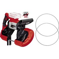
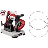
| Product type | Combined electric saw (table saw and mitre saw) |
| Brand | Einhell |
| Model | TCMS 3017 T |
| Power supply | 230-240 V ~ 50 Hz |
| Power | 2000 W (S1 duty) |
| No-load speed | 4200 rpm |
| Saw blade | Ø 305 x Ø 30 x 3.2 mm, 40 teeth carbide |
| Weight | Approximately 17.5 kg |
| Saw table (table mode) | 466 x 400 mm |
| Max. cutting depth (table mode) | 50 mm |
| Cutting capacity (mitre saw mode, 90°) | 170 x 85 mm |
| Cutting capacity (mitre saw mode, 45°) | 110 x 85 mm |
| Head pivot range | -45° to +45° (left) |
| Turntable rotation range | -45° to +45° |
| Parallel stop | Pivotable from -45° to +45° |
| Dust extraction connection | 36 mm |
| Sound pressure level (LpA) | 99.1 dB(A), uncertainty K=3 dB |
| Sound power level (LWA) | 112.1 dB(A), uncertainty K=3 dB |
| Electric brake | Yes, for the saw blade |
| Included accessories | Parallel/cross stop, push stick, workpiece supports, pin wrench, hex key, dust extraction connection |
Frequently Asked Questions - TCMS 3017 T EINHELL
User questions about TCMS 3017 T EINHELL
0 question about this device. Answer the ones you know or ask your own.
Ask a new question about this device
Download the instructions for your Electric saw in PDF format for free! Find your manual TCMS 3017 T - EINHELL and take your electronic device back in hand. On this page are published all the documents necessary for the use of your device. TCMS 3017 T by EINHELL.
USER MANUAL TCMS 3017 T EINHELL
Danger! - Read the operating instructions to reduce the risk of injury

Caution! Wear ear-muffs. The impact of noise can cause damage to hearing.

Caution! Wear a breathing mask. Dust which is injurious to health can be generated when working on wood and other materials. Never use the device to work on any materials containing asbestos!

Caution! Wear safety goggles. Sparks generated during working or splinters, chips and dust emitted by the device can cause loss of sight.

Caution! Risk of injury! Do not reach into the running saw blade.
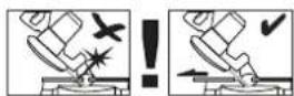
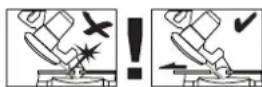
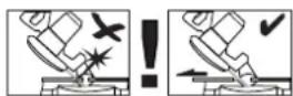
Warning! To make miter cuts (with the saw head inclined or the turntable set at an angle), the adjustable stop rail must be fixed at an outer position.
To make 90^ crosscuts, the adjustable stop rail must be fixed at the inner position.
GB
Danger!
When using the equipment, a few safety precautions must be observed to avoid injuries and damage. Please read the complete operating instructions and safety regulations with due care. Keep this manual in a safe place, so that the information is available at all times. If you give the equipment to any other person, hand over these operating instructions and safety regulations as well. We cannot accept any liability for damage or accidents which arise due to a failure to follow these instructions and the safety instructions.
1. Safety regulations
The corresponding safety information can be found in the enclosed booklet.
Danger!
Read all safety regulations and instructions. Any errors made in following the safety regulations and instructions may result in an electric shock, fire and/or serious injury.
Keep all safety regulations and instructions in a safe place for future use.
2. Layout and items supplied
2.1 Layout (Fig. 1-3)
- Release button
- Handle
- ON/OFF switch for crosscut mode
- ON/OFF switch for table mode
- Saw blade
- Movable blade guard
- Stop rail
- Turntable
- Bottom saw table
- Locking screw for turntable
- Scale
- Bottom table insert
- Mounting for workpiece supports
- Bottom saw blade cover
- Locking screw
- Saw bench
- Top saw blade guard
- Cross and parallel stop
- Hexagon key
- Workpiece supports
- Face spanner
- Tightening screw
- Safety pin
-
Locking screw
-
Screw for miter setting
- Knurled screw
- Stop rail
- Locking screw for cutting width
- Push stick
- Splitter
- Extractor port
- Extractor socket
- Arrow
- Outer flange
- Arrow
37.Clamp - Recessed handle
- Adjustable stop rail
- Locking screw for adjustable stop rail
2.2 Items supplied
Please check that the article is complete as specified in the scope of delivery. If parts are missing, please contact our service center or the sales outlet where you made your purchase at the latest within 5 working days after purchasing the product and upon presentation of a valid bill of purchase. Also, refer to the warranty table in the service information at the end of the operating instructions.
- Open the packaging and take out the equipment with care.
- Remove the packaging material and any packaging and/or transportation braces (if available).
Check to see if all items are supplied. - Inspect the equipment and accessories for transport damage.
If possible, please keep the packaging until the end of the guarantee period.
Danger!
The equipment and packaging material are not toys. Do not let children play with plastic bags, foils or small parts. There is a danger of swallowing or suffocating!
Cross and parallel stop
Push stick
Workpiece supports
Face spanner
- Hexagon key
- Dust extraction connector
Original operating instructions
Safety information
GB
3. Proper use
The crosscut and miter saw with table is designed for cross-cutting and for the longitudinal and lateral cutting (with cross stop only) of wood and plastic suitable for the machine size.
The machine is not to be used for cutting fire wood. The machine is to be used only for its prescribed purpose. Any use other than that mentioned is considered to be a case of misuse. The user/operator and not the manufacturer shall be liable for any damage or injury resulting from such cases of misuse. The machine is to be operated only with suitable saw blades. It is prohibited to use any type of cutting-off wheel.
To use the machine properly you must also observe the safety regulations, the assembly instructions and the operating instructions to be found in this manual. All persons who use and service the machine have to be acquainted with this manual and must be informed about its potential hazards. It is also imperative to observe the accident prevention regulations in force in your area.
The same applies for the general rules of occupational health and safety.
The manufacturer shall not be liable for any changes made to the machine nor for any damage resulting from such changes.
Even when the machine is used as prescribed it is still impossible to eliminate certain residual risk factors. The following risks may arise due to the machine's design and setup:
- Contact with the saw blade in the uncovered saw zone.
- Reaching into the running saw blade (cut injuries).
- Kick-back of workpieces and parts of workpieces.
Saw blade fracturing. - Catapulting of faulty carbide tips from the saw blade.
- Damage to hearing if essential ear-muffs are not worn.
- Harmful emissions of wood dust when the machine is used in closed rooms.
The equipment is to be used only for its prescribed purpose. Any other use is deemed to be a case of misuse. The user / operator and not the manufacturer will be liable for any damage or injuries of any kind caused as a result of this.
Please note that our equipment has not been designed for use in commercial, trade or industrial
applications. Our warranty will be voided if the machine is used in commercial, trade or industrial businesses or for equivalent purposes.
4. Technical data
AC motor. 230-240 V ~ 50 Hz
Power. 2000W
Operating mode .S1
ldling speed n. 4200 min-1
Carbide saw blade 305 x 0 30 x 3,2 mm
Number of teeth 40
Extractor socket 36 mm
Weight. approx. 17.5 kg
For use as a bench-type saw:
Saw table 466 x 400 mm
Cutting depth max. 50 mm
Minimum size of the workpiece 15 × 10 × 100 ~mm
Parallel stop ....Can be pivoted from -45^ to +45^
For use as a crosscut saw:
Pivoting range -45°/0°/+45°
Miter cut. 0^ to 45^ to the left
Saw width at 90^ 170x85mm
Saw width at 45^ 110x85mm
Saw width at 2 × 45^
(Double miter cut to the left) .75 x 50 mm
(Double miter cut to the right) 110 x 50 mm
Minimum size of the workpiece 50 × 10 × 100 mm
Danger!
Sound and vibration
Sound and vibration values were measured in accordance with EN 61029.
Sound pressure level L_PA 99.1 dB(A)
Uncertainty K 3 dB
The impact of noise can cause damage to hearing.
The specified vibration value was established in accordance with a standardized testing method. It may change according to how the electric equipment is used and may exceed the specified value
GB
in exceptional circumstances.
The specified vibration value can be used to compare the equipment with other electric power tools.
The specified vibration value can be used for initial assessment of a harmful effect.
Keep the noise emissions and vibrations to a minimum.
Only use appliances which are in perfect working order.
Service and clean the appliance regularly.
Adapt your working style to suit the appliance.
Do not overload the appliance.
- Have the appliance serviced whenever necessary.
- Switch the appliance off when it is not in use.
Caution!
Residual risks
Even if you use this electric power tool in accordance with instructions, certain residual risks cannot be rules out. The following hazards may arise in connection with the equipment's construction and layout:
- Lung damage if no suitable protective dust mask is used.
- Damage to hearing if no suitable ear protection is used.
- Health damage caused by hand-arm vibrations if the equipment is used over a prolonged period or is not properly guided and maintained.
5. Before starting the equipment
Before you connect the equipment to the mains supply make sure that the data on the rating plate are identical to the mains data.
Warning!
Always pull the power plug before making adjustments to the equipment.
The machine has to be set up in a stable position, i.e. it has to be bolted to a workbench, a universal stand or the like.
- All the covers and safety devices have to be properly fitted before the machine is switched on.
It must be possible for the saw blade to run freely.
- When working with wood that has been pro
cessed before, watch out for foreign bodies such as nails or screws etc.
Before you actuate the On/Off switch, make sure that the saw blade is correctly fitted and that the machine's moving parts run smoothly.
Before you connect the machine to the power supply, make sure the data on the rating plate is the same as that for your mains.
- Secure the clamp (37) on the top of the stop rail using the screw.
5.1 Setting up the saw (Fig. 1-4)
- Insert the two workpiece support clips (20) in the mounts (13) provided on the side of the tool and fasten them in place with screws.
To prevent the saw from toppling backwards, the additional foot (a) must be pulled out of the equipment (Fig. 4).
5.2 Converting the combination saw (Fig. 1-8)
The saw has two working positions:
A: Bench circular saw (Fig. 1)
B: Crosscut and miter saw (Fig. 2)
Convert the combination saw can be converted exactly as described below, otherwise the components may be damaged.
Important: Pull out the mains plug before you convert the saw.
When it is supplied, the saw will be in mode A (bench circular saw)
5.2.1 Converting the saw for crosscut mode (Fig. 5, 6)
- Tighten the locking screw (10) and the tightening screw (22).
- Undo the locking screws (15, 24) and lift the saw table so that it moves into the highest position. Tighten the two locking screws again.
- Press the saw table (16) down at the front and draw the safety pin (23) out at the same time.
- Caution! The return spring automatically lifts the machine. Do not let go of the saw table, but move it slowly up to the swung-out position by applying counterpressure.
- When you draw out the safety pin (23), this deactivates the switch (4) for bench mode and activates the switch for crosscut mode (3).
- Remove the bottom saw blade cover (14).
The saw has now been set to crosscut mode.
5.2.2 Converting the saw for bench mode (Fig. 5-7)
GB
- Move the machine head upwards and the turntable to the 0^ position.
- Tighten the locking screw (10) and the tightening screw (22).
- Position the bottom saw blade cover (14) on the turntable so that it engages behind the stop rail (7).
- Press the release button (1) and lower the machine using the handle (2) until the bottom saw blade guard (14) completely covers the saw blade.
- Press the saw table (16) down at the front and press the safety pin (23) in at the same time.
- When you press in the safety pin (23), this activates the switch (4) for bench mode and deactivates the switch for crosscut mode (3).
- Undo the locking screws (15, 24) and lower the saw table until the desired cutting height is reached for the saw blade.
- Tighten the two locking screws again.
The saw has now been set to bench mode.
5.3 Adjusting options for the saw in crosscut mode (Fig. 1/2)
- Undo the locking screw (10) approx. 2 turns to adjust the turntable (8).
The turntable (8) has locking points at angles of 0^ , 15^ , 22.5^ , 30^ and 45^ . Once the turntable (8) is engaged, the setting must also be secured by tightening the locking screw (10).
If different angle settings are required, the turntable (8) may be secured in position using only the locking screw (10). - Swing up the machine head.
- When the tightening screw (22) is loosened, you can tilt the machine head to the left by up to 45^ .
5.4 Precision adjustment of the stop for crosscut 90^ (Fig. 1-3/9/10)
Lower the machine head and fasten in place with the safety pin (23).
Slacken the tightening screw (22).
- Place the angular stop (a) between the blade (5) and the turntable (8).
- Slacken the counternut (b) and adjust the adjustment screw (c) until the angle between the blade (5) and the turntable (8) equals 90^ .
- Retighten the counternut (b) to secure this setting.
5.5 Precision adjustment of the stop for miter cut 45^ (Fig. 1-3/11/12)
Lower the machine head and fasten in place with the safety pin (23).
- Fasten the turntable (8) in 0^ position.
- Undo the tightening screw (22) and use the handle (2) to tilt the machine head to the left until it coincides at 45^ .
- Place the 45^ stop angle (f) between the blade (5) and the turntable (8).
- Slacken the counternut (d) and adjust the adjustment screw (e) until the angle between the blade (5) and the turntable (8) equals 45^ .
- Retigthen the counternut (d) to secure this setting.
5.6 Sawdust extraction (Fig. 13)
The machine is equipped with an extractor socket (32) and also with an extractor port (31) which can be fastened to the top saw blade guard.
This means that the machine can be connected to standard sawdust extractors.
- Never use the equipment without the suction function. Regularly check and clean the suction channels.
5.7 Changing the saw blade (Fig. 14-19) Caution! Unplug the device from the mains power.
Caution! Always wear gloves when handling the saw blade.
- Set the saw to crosscut mode (see 5.2.1).
- Undo the screw (g) on the lever (h).
- Place the face spanner (21) on the outer flange (35) and undo the saw blade screw by turning it in a clockwise direction using the Hexagon key.
- Remove the saw blade (5) from the inner flange
Thoroughly clean the motor shaft and flange before you fit and secure the new saw blade. - Important! The cutting angle of the teeth and the direction arrow on the saw blade must coincide with the direction of the arrow on the housing.
- Caution! Retighten the lever (h) on the housing using the screw (g). Check that the saw blade guard closes automatically when the machine head is moved upwards before you start using the machine.
The splitter is pre-set at the factory. If you adjust the settings of the splitter, you must make sure that there is a gap of 3 - 5mm between the teeth of the saw blade and the splitter and that the splitter is securely tightened.
GB
6. Operation
After every new adjustment we recommend you to make a trial cut in order to check the new settings.
Warning! To make 90^ crosscuts, the adjustable stop rail (39) must be fixed at the inner position:
- Undo the locking screw (40) of the adjustable stop rail and push the adjustable stop rail inwards.
The adjustable stop rail (39) must be fixed far enough in front of the innermost position that the distance between the stop rail (39) and the saw blade (5) amounts to a maximum of 5mm .
Before making a cut, check that the stop rail and the saw blade cannot collide. - Tighten the locking screw (40) again.
Warning! To make 0^ - 45^ miter cuts (with the saw head inclined or the turntable set at an angle), the adjustable stop rail (39) must be fixed at an outer position.
- Undo the locking screw (40) of the adjustable stop rail and push the adjustable stop rail outwards.
- The adjustable stop rail (39) must be fixed far enough in front of the innermost position that the distance between the stop rail (39) and the saw blade (5) amounts to a maximum of 5mm .
Before making a cut, check that the stop rail and the saw blade cannot collide. - Tighten the locking screw (40) again.
6.1 Use as a bench saw (Fig. 1)
Setting the saw to bench mode (see 5.2.2./6)
Take extra care when starting the cut.
6.1.1 On/Off switch (Fig. 18)
The saw can be switched on by pressing the green pushbutton (I). Wait for the blade (5) to reach its maximum speed before starting the cut.
The red pushbutton (0) has to be pressed to switch off the saw.
6.1.2 Adjusting the cutting depth
- Undo the locking screws (15, 24) and lower the saw table until the desired cutting height is reached for the saw blade.
- Tighten the two locking screws again.
6.1.3 Longitudinal cuts (Figure 20-22)
- Undo the knurled screw (25) and set the cross and parallel stop (18) to 90^ . Tighten the knurled screw (25) again.
- Fit the parallel stop (18) from the right into the front groove in the saw bench (16).
- Undo the two knurled screws (26). Carefully push the stop rail (27) to over the middle of the saw blade (5) and secure it.
- Set the parallel stop (18) to the required dimension using the scale (c) on the saw bench (16) and secure it with the locking screw (28).
- Switch on the saw by pressing the green button (l).
- Slide the workpiece slowly and precisely along the parallel stop (18) to the saw blade (5).
The top saw blade guard (17) will open automatically and the workpiece moves forward. - Important: For workpiece widths below 120 mm a push stick (29) must be used in the area near the saw blade (5) (see Fig. 21) (supplied). For workpiece widths below 30 mm a push block (d) must be used to move the workpiece. The push block is not supplied. (Available from your specialist dealer)
Always push the workpiece through to the end of the splitter (30).
After completing the cut the safety hood (17) will close again automatically to cover the saw blade (5). - Switch off the saw again.
- Important: Secure long workpieces against falling off at the end of the cut (e.g. with a roller stand etc.) (e.g. roller table etc.)
6.1.4. Making cross cuts (Fig. 20-22)
- Fit the cross parallel stop (18) from the front into the side groove in the saw bench (16).
- Tighten the locking screw (28) until the cross and parallel stop (18) can be moved in the groove in the saw bench (16) with a little play.
- Undo the screw (25), set the cross stop (18) to the required angle and secure it.
- Undo the two knurled screws (26) and slide the stop rail (27) to the left until it do not touch the saw blade guard (17) when it is moved forwards. Retighten the knurled screws (26).
- Switch on the saw.
- Press the workpiece firmly against the stop rail (27) and slide it slowly into the saw blade (5) together with the cross and parallel stop (18) to complete the cut.
GB
After completing the cut, switch off the saw again.
6.2. Using as a crosscut saw Set the saw to crosscut mode (see 5.2.1)
6.2.1 Settings (Abb. 2/3)
- When the tightening screw (22) is loosened, you can tilt the machine head to the left by up to 45^ .
The turntable (8) can be adjusted from -45^ to +45^ by undoing the locking screws.(10) - Start the saw by pressing the On/Off switch (3). The switch must remain pressed during the sawing work.
6.2.2 Crosscut 90^ and turntable 0^ (Fig. 2-3/23)
- Press the On/Off switch (3) to turn on the saw.
- Important. Place the material for sawing firmly on the machine surface and secure it with the clamp (37) to prevent it from moving during the sawing process.
- When you have switched on the saw, wait until the saw blade (5) has reached maximum speed.
- Press the release lever (1) and, using the handle (2), apply steady and light downward pressure to move the machine head through the workpiece.
After the cutting process is finished, bring the machine head back to its upper (home) position and release the ON/OFF button (3). Important. The integral resetting springs will automatically lift the machine head. Do not simply let go of the handle (2) after cutting, but allow the machine head to rise slowly, applying slight counterpressure as it does so.
6.2.3 Crosscut 90^ and turntable 0^ - 45^ (Fig. 2-3/24)
The crosscut and miter saw with table can be used to make right and left angular cuts of 0^ - 45^ in relation to the stop rail.
- Move the machine head to its upper position.
- Release the turntable (8) by slackening the locking screw (10).
Using the handle (2), set the turntable (8) to the desired angle, i.e. the marking (a) on the turntable must coincide with the desired angular setting (11) on the stationary base plate (9). - Retighten the locking screw (10) to secure the turntable (8) in place.
Cut as described under section 6.2.2.
6.2.4 Miter cut 0^ - 45^ and turntable 0^ (Fig. 2-3/25)
The crosscut and miter saw with table can be used to make miter cuts of 0^ - 45^ in relation to the work face.
- Move the machine head to its upper position.
- Fasten the turntable (8) in 0^ position.
- Undo the tightening screw (22) and use the handle (2) to tilt the machine head to the left until the pointer (b) coincides with the required angle value.
- Retighten the tightening screw (22) and make the cut as described in section 6.2.2.
6.2.5 Miter cut 0^ - 45^ and turntable 0^ - 45^ (Fig. 2-3/26)
The crosscut and miter saw with table can be used to make miter cuts to the left of 0^ - 45^ in relation to the work face and, at the same time, 0^ - 45^ in relation to the stop rail (double miter cut).
- Move the machine head to its upper position.
- Release the turntable (8) by slackening the locking screw (10).
Use the handle (2) to adjust the turntable (8) to the angle required (in this connection see also section 6.2.3). - Retighten the locking screw (10) in order to secure the turntable in place.
- Undo the tightening screw (22) and use the handle (2) to tilt the machine head (4) to the left until it coincides with the required angle value (in this connection see also point 6.2.4).
Screw the tightening screw (22) back down again.
Cut as described under section 6.2.2.
6.3 Electric brake
For safety reasons, the equipment is supplied with an electric brake system for the saw blade. The equipment may therefore emit an odor or generate sparks when it is switched off. This has no influence on the operational performance or safety of the equipment.
GB
7. Replacing the power cable
Danger!
If the power cable for this equipment is damaged, it must be replaced by the manufacturer or its after-sales service or similarly trained personnel to avoid danger.
8. Cleaning, maintenance and ordering of spare parts
Danger!
Always pull out the mains power plug before starting any cleaning work.
8.1 Cleaning
- Keep all safety devices, air vents and the motor housing free of dirt and dust as far as possible. Wipe the equipment with a clean cloth or blow it with compressed air at low pressure.
We recommend that you clean the device immediately each time you have finished using it.
Clean the equipment regularly with a moist cloth and some soft soap. Do not use cleaning agents or solvents; these could attack the plastic parts of the equipment. Ensure that no water can seep into the device. The ingress of water into an electric tool increases the risk of an electric shock.
8.2 Carbon brushes
In case of excessive sparking, have the carbon brushes checked only by a quali edlectrician. Danger! The carbon brushes should not be replaced by anyone but a quali edlectrician.
8.3 Maintenance
There are no parts inside the equipment which require additional maintenance.
Lubricate all moving parts at regular intervals.
8.4 Ordering spare parts and accessories
Please provide the following information when ordering spare parts:
Type of unit
Article number of the unit
ID number of the unit
- Spare part number of the required spare part For our latest prices and information please go to www.isc-gmbh.info
Tip! For good results we recommend high-quality accessories from www.kwb.eu welcome@kwb.eu
9. Disposal and recycling
The equipment is supplied in packaging to prevent it from being damaged in transit. The raw materials in this packaging can be reused or recycled. The equipment and its accessories are made of various types of material, such as metal and plastic. Never place defective equipment in your household refuse. The equipment should be taken to a suitable collection center for proper disposal. If you do not know the whereabouts of such a collection point, you should ask in your local council offices.
10. Storage
Store the equipment and accessories in a dark and dry place at above freezing temperature. The ideal storage temperature is between 5 and 30 ^ C . Store the electric tool in its original packaging.
GB

For EU countries only
Never place any electric power tools in your household refuse.
To comply with European Directive 2012/19/EC concerning old electric and electronic equipment and its implementation in national laws, old electric power tools have to be separated from other waste and disposed of in an environment-friendly fashion, e.g. by taking to a recycling depot.
Recycling alternative to the return request:
As an alternative to returning the equipment to the manufacturer, the owner of the electrical equipment must make sure that the equipment is properly disposed of if he no longer wants to keep the equipment. The old equipment can be returned to a suitable collection point that will dispose of the equipment in accordance with the national recycling and waste disposal regulations. This does not apply to any accessories or aids without electrical components supplied with the old equipment.
The reprinting or reproduction by any other means, in whole or in part, of documentation and papers accompanying products is permitted only with the express consent of the iSC GmbH.
Subject to technical changes
- The product meets the requirements of EN 61000-3-11 and is subject to special connection conditions. This means that use of the product at any freely selectable connection point is not allowed.
- Given unfavorable conditions in the power supply the product can cause the voltage to fluctuate temporarily.
The product is intended solely for use at connection points that a) do not exceed a maximum permitted supply impedance 0,248 or b) have a continuous current-carrying capacity of the mains of at least 100 A per phase. - As the user, you are required to ensure, in consultation with your electric power company if necessary, that the connection point at which you wish to operate the product meets one of the two requirements, a) or b), named above.
GB
Service information
We have competent service partners in all countries named on the guarantee certificate whose contact details can also be found on the guarantee certificate. These partners will help you with all service requests such as repairs, spare and wearing part orders or the purchase of consumables.
Please note that the following parts of this product are subject to normal or natural wear and that the following parts are therefore also required for use as consumables.
| Category Example | |
| Wear parts* Carbon brushes | |
| Consumables* Saw blade, Push stick | |
| Missing parts |
- Not necessarily included in the scope of delivery!
In the effect of defects or faults, please register the problem on the internet at www.isc-gmbh.info. Please ensure that you provide a precise description of the problem and answer the following questions in all cases:
Did the equipment work at all or was it defective from the beginning?
Did you notice anything (symptom or defect) prior to the failure?
- What malfunction does the equipment have in your opinion (main symptom)?
Describe this malfunction.
GB
Warranty certificate
Dear Customer,
All of our products undergo strict quality checks to ensure that they reach you in perfect condition. In the unlikely event that your device develops a fault, please contact our service department at the address shown on this guarantee card. You can also contact us by telephone using the service number shown. Please note the following terms under which guarantee claims can be made:
- These guarantee terms apply to consumers only, i.e. natural persons intending to use this product neither for their commercial activities nor for any other self-employed activities. These warranty terms regulate additional warranty services, which the manufacturer mentioned below promises to buyers of its new products in addition to their statutory rights of guarantee. Your statutory guarantee claims are not affected by this guarantee. Our guarantee is free of charge to you.
- The warranty services cover only defects due to material or manufacturing faults on a product which you have bought from the manufacturer mentioned below and are limited to either the rectification of said defects on the product or the replacement of the product, whichever we prefer. Please note that our devices are not designed for use in commercial, trade or professional applications. A guarantee contract will not be created if the device has been used by commercial, trade or industrial business or has been exposed to similar stresses during the guarantee period.
-
The following are not covered by our guarantee:
-
Damage to the device caused by a failure to follow the assembly instructions or due to incorrect installation, a failure to follow the operating instructions (for example connecting it to an incorrect mains voltage or current type) or a failure to follow the maintenance and safety instructions or by exposing the device to abnormal environmental conditions or by lack of care and maintenance.
- Damage to the device caused by abuse or incorrect use (for example overloading the device or the use or unapproved tools or accessories), ingress of foreign bodies into the device (such as sand, stones or dust, transport damage), the use of force or damage caused by external forces (for example by dropping it).
-
Damage to the device or parts of the device caused by normal or natural wear or tear or by normal use of the device.
-
The guarantee is valid for a period of 24 months starting from the purchase date of the device. Guarantee claims should be submitted before the end of the guarantee period within two weeks of the defect being noticed. No guarantee claims will be accepted after the end of the guarantee period. The original guarantee period remains applicable to the device even if repairs are carried out or parts are replaced. In such cases, the work performed or parts fitted will not result in an extension of the guarantee period, and no new guarantee will become active for the work performed or parts fitted. This also applies if an on-site service is used.
-
To make a claim under the guarantee, please register the defective device at: www.isc-gmbh.info. Please keep your bill of purchase or other proof of purchase for the new device. Devices that are returned without proof of purchase or without a rating plate shall not be covered by the guarantee, because appropriate identification will not be possible. If the defect is covered by our guarantee, then the item in question will either be repaired immediately and returned to you or we will send you a new replacement.
Of course, we are also happy offer a chargeable repair service for any defects which are not covered by the scope of this guarantee or for units which are no longer covered. To take advantage of this service, please send the device to our service address.
Also refer to the restrictions of this warranty concerning wear parts, consumables and missing parts as set out in the service information in these operating instructions.
F

Chere cliente, cher client,
Bring savens overdel i overste position.
OcToPOnHNO!IcNoJIb3yIte pecnnpaTOp. PnO6pa6OTHE dpeBecNbI IN DpyrNX MaTePnaIOB MoKeT o6pa3oBaTbcra BpeHaJn 3IopOBbIpbIb. 3anpeSeHO 6pa6aTbIBaTB npedMeTbI cOepKaUne ac6ect!

OctopoHHo! NcnoJIb3yIte 3aunTHbIe OCHN. Bo3HnKaIOUe BO BpEma pa6Otbl NCKpbI INB bIeJIaIOUncEa H3 yCTpoIcTBa OBJLOMKn, ONIIKN I nblb MOrT NOBpeDITb OprAhbl 3peHHa.

OctopokHO! Onachocb noJyehn TpaBm! He 6paTbc 3a DBnraUoeeecr NnIbHoe noIOTHO.
PpeynpekenHeH! JI KOCORO NIIeHn (npa6oTe c HAnIOHeHNOIOLBKOINIIbI IHa NOBOPOTOM CTOJIe C yCTAHOBENHbIM YrIOM) CMeUaEmay yNOpHaa WnHa DoJIXHa 6bITb3aFHKcPOBaHa B NOLOKeHHn ChapyKn. JI TopoBOrO NIIeHn ND yrIOM 90° CMeUaEmay yNOpHaa WnHa DOnJHb 6bITb 3aFHKcPOBaHa B NIOXeHHn BNYTpN.
RUS
Onachoctb!
PnHcNoIb3OBAHHYCTPOINCTB Heo6xOIMO
C0bIIOaTb ONpeIeHNbIe npABHnA TeHXNk
6eONaCHOCHTn IJI TORO, YTObIi N6EHaTb
TPaBMn INpeDfBpATNTb yUep6. No3tOMy
BHIMaTeBHO pOuHTaHTe HAcToJee
pyKOBOCTBO NO 3KcIIpyATAun / yKa3AHnno
TEXHnHE 6eONaCHOCHTn NOHCTbIO. XpaHnTe
NX B HAedeXHM OMeTE IJI TORO, YTObIi IMeTb
Heo6xOIMyIO INΦOpMaUnIO, KOrDa OHa
NoHaObHTcA. Ecln Bbl Daete YCTPOCTBO
dpyHM IJI NOIb3OBaHHN, TO pNILOHnTE K HEMy
3TO pyKOBoDCTBO NO 3KcIIpyATAun / yKa3AHnna
NO TexHnke 6eONaCHOCHTn. Mbl He Hecem
HnKaKoI OTBETCTBEHOCHTn 3a TpaBMbl N Ueep6,
KOTOpBle 6bln NOnyueHbI NnPiuHHehbl
B pe3yIbTaTE Hco6IIODeHHy yKa3AHn
3TORO pyKOBoCTBa N yKa3AHn no TexHnke
6eONaCHOCHTn.
1.Yha3aHHNo TExHnHe 6e3onacHOCTN
Co0TBeTCTByUOHe yKa3aHnNo TeXnHKe 6e3oNaCHOCn HaxoJrTCB B npuIOKeHHbIX 6poUxpax!
OnachocTB!
IpoHTaTe BCE yKa3aHnNo TExnHKe 6e3oNaCHOCn nTexnHuEChne Tpe6oBaHn
PiNe HeBbINOJIHeHn yKa3aHn No TExnHKe 6e3oNaCHOCn n TexnHuEChnx Tpe6oBaHn BO3MOxHO NpUyHeHne Udapa TOKOM, BO3HNHOBHeHne NpOka n/INn NpUyHeHne cpe3bHX TpaBM. XpaHnTe BCE yKa3aHn
NO TexnHKe 6e3oNaCHOCn n TexnHuEChne Tpe6oBaHn dIra TORO, YTObI bIIO BO3MOxHO BOCNtB3OBaTbcR HmN B 6dyueem.
2. CoCTAB yCTPOHCTBA n COCTAB yNaHOBHN
2.1 CoCTaB yCtpoHCTBa (pncyHHN 1-3)
1.Honka De6loKupOBKn
2. Rykortha
3. PepeklouateBbKIOHTb-BbIKIOHTb DJIpeKIMATOPOBOIINJIbl
4. NpeKIOHcATEb BHIIOHTb-BbIKIOHTb IHaCTOJIbHO PeKIMa
5. NnIbHoe nOToTHo
6. 3aunTa nnJbHoro noIOTHa noDnHexHae
7. ynpnha uHa
-
NOBOPOTbI CToT
-
HnKnn CTOn nJIbI
-
CtonopHbIN BnHT DnI NOBOPTHOrO CTOna
-
Shkana
-
BCTaBkA CToJa HNKHJRA
-
PnemHoe npncocObeHne dIra onopbIobpaBaBaEmbIX DeTalei
-
HnKnra 3aunTa nHbHoro noLoTHa
15.YCTaHOBOUHbIN BnHT
-
CToI nHbI
-
BepxHra 3aunTa nnIbHoro noIoTHa
-
PonepeuHbI nI npapallehBHy ynp
19.нлочьВHTpeHHM WeCTHpaaHHKOM
-
Onopbl obpaabaBbAeMbix DeTaeH
-
HauNDHOI KIOU
22.3aXMMHOBINHT
- PpeoxpaHnTeIbHbI 6oT
24.YCTaHOBOUHbI BnHT
25.BnHTIpepynilpoBKn pe3Kn noyrrnom
-
BnHT cHaKaTaHHoI rOJIOBkoI
-
Ynopna shna
-
CToOpHbI BnHT dIpeRyIpOBKn IipHHbI pe3aHnA
-
WToK-ToJkaTeIb
-
KIMH
-
AcnpaunonHbni naTpy60
32.山TucepIINIOCoEINHENOTcacbBAUoeroyctpoCTBa
- Ctpenka
- Bheunn fnaHeu
- CtrpeIka
- 3aKIM
- BbIeMka 3aXBaTa
- Cmeaemayynopna shHa
40.YctaHOBOUHbI BNHT DnA CMeuaemOyNOPHOI WINHbI
2.2 CoCTAB KOMNJIeKTA yCTPOJCTBa
IpoBepbTe KOMnJIeHTOcTb H3dEINHa OCHOBAHN ONHCaHHOro 06bema NocTaBH.N.
Pn OBapyKeHN HeOcTaTHa KOMNoHETOB O6paNTecb B hau CepBnchb YcHtp
Hm Mara3IN, B KOtOpom Bbl npHO6pEN
ycTrooCTBO, He NO3dHee cem B TeueHne 5-Tn
paOvHX dHeN oCnOE pno6peTeHN H3dEIN,
npDeBbVB DcETCBtEnbHyIO KBtAnuIO O
OKynHe. Obpatte BNImaHne Ha TabiCy C
yk3aHHeM rapaHTnHbIX cPoKOB B DOkHMeHTe C
HhOpMaune O cepBnCHOM OcbLyJxBaHIn.
- OTKpOIne ynaKOBky N BbIHbTe OCTOpOKHO n3 ynaKOBKn YCTPOINCTBO.
- YdaJIte ynaKOBOHyMaTePnAn, a TaKHe npHCnocO6JeHn3aUHTbYcTPOIcTBa npu ynaKOBbBaHnN n TpaHCnOpTIpOBKe (npn HauyHn).
RUS
- IpoBepbTe KOMJIeKTHoCTb yCTPOIcTBA.
- PpOBeBpTe yCtpoCTBO n npHaJnEeKHOCTn Ha HAnuHne BO3NkWux npi TpaHCnpTnpOBKe NOpeKdEnH.
CoxpaHnTe ynaKOBky no BO3MOxHocTn Do nCTeueHnCpoka rapaHTnHbIX 063aTeIbCTB.
OnachocTb!
YcTpoIcTBOn ynaHOBKa He ABJIOTc
dETCHMM HpyuWkAm! 3anpeeHO DetAM
HRpaTb CnlaCTHOBBIMn NaKetAmn,
PiEHHAMn MEHKnM DeTaJAMn! OnaCHOctb
3AHLOaETcB TOM, YTO OHN MOrYT
npornotb HnN NnOH6Hyt b OT yduyBa!
- PonepeuHbI nI npaIJIeJIbHbI ynp
- TOK-TOKKaTeIb
Onopb6pa6aTbIbAembIxTeTaJIe
Hakundon Klnoy
Klnou C BNYtpeHHM WecTnRpaHHNKOM
山tycepIJnnoCoeHHeNHO TcAsbIAUoero yCTpOInCTBa
OpHnHaJIbHoe pyHOBOcTBo nO 3KcNlyaTaun - Yka3aHnI NO TexHnke 6e3oNaCHOCTN
Cbeinte 6pa3OBaHne WymoN Bn6paun K MHHMMyM!
VcnoIb3yIteToIbKO6e3yKOpn3HeHHO paOtaIOUneycTpoIcTBa.
PeryIpaHNO npoBOnTe texHueckoe 06cIyKbHAHne I OCHCTky yCTpoHCTBa.
- Pn pa60te yuHTbIaIte OocbeHHocTn BaJero ycTpoIcTa.
He noDBepraIte yCTpoIcTBO nepepy3ke.
Pn Heo6xOUMOCTN daTpe npOBepntb yctpoCTBO CNEuaJNCTam.
- OTHJUOaYte yCTpoIcTBO, ecJIbI eRr He HcNoJIb3YeTe.
OctopoKHO!
OctatoHbIe ONaCHOCTN
AaHe B Tom Cnyae,ecn HbI HcNoB3yeTe ONCbBaembl 3eKTPueChm HNCTpyMeHT B COOTBeTCTBnC npeDnCaHMe,TO H TOrda BCerda OctaTeC MeTo Dn Pncha.HnKe npHBeden CnHCOH OCTaTOhBIX ONaCHOCTei, CBzAAHHbIX C HOHCTpyHneH HactoJero 3JIeKTPueCHO HNCTpyMeHTa:
- 3a6oJIeBaHHe JERKHX, B TOM Clyuae ecnI He IcNoJIb3yETcR COOTBeTCTByUOuN peCnnpaTOP.
2.Поврждени Слуха,ВТOMСлчаеECINHe HcNoIb3yETC8 COOTBETCTBHyOuSe CpeDCTBO 3aunTbI Clyxa.
3.HapuHnna 3doOpBbBa Bpe3yIbTaTe Bo3deIeCTBnB Hb6paunnHa pyky npn DInTtehHom nCnoJb3OaHnn yCtroiCTBa nnPi npHePpauHbHom POnJb3ObaHnn N HeHaJIeKaUeM TEXHnuecKOM yXoJe.
RUS
5. Ipepe BBODOM B3Hcnpnyatauio
Y6eHTecb nepei noKluoyehnem, YTO daHHbe Ha TINOBoTabNue KootBETCTByOT npametpam cTe.
Ppeynpexdene!
Bcerda BbHMaTe wTeKeH n03po3TK npEnIe, Yem OcyueCTBnTb HacTpOHN ycTpoNCTBa.
Heo6xOIMO o6eCneuHt yCToHNUBOcTB yCTpoIcTBA,TO eCTb npINBHTnTb eTo 4-MB HNTaMn K BepCTaKy, yHbEPcaJIbHOI NOCTABKe I T.I.
HeobxOaHMoHaJnEJaMmO6pa3oM yctAHOBnTb BCE KpbIuKN H3aUHTbIe npncnoc6JIeHn.
- PnloTHo nHbI dOJIHKHO Bpaaatbc86e3 NOMEX.
PnO6pa60TepeBcHHbIXN3deJnHHe6XoDMO yueCTb HANHne NOCTOPOHHXnpEaMeTOB,HaNPmEp, rBO3dIN NIN WpyNbI T.D.
IpeKdE Yem npBecTH B DeiCTBHe BkIOUcATEJIy b6eINTEcB, 7TO NIOLOTHO NIIbI yCTaHOBJIeHO npaBnJIbHO I NOdBHXHbIE DeTALN He HmEHOT NOMEX.
IpeD noHIOHeHm MaHnHbI y6eHTecb, YTO daHHbe, pNBEdeHHbe Ha TINOBO TaBnUHe, COOTBETCTByOT npaMeTpam 3NeKTpocetH.
3aKpeNtB 3aKIM (37) npn nOmoU BNHTa Ha BepXHeN CTOpOHE ynpHOH uINbI.
5.1 C6opHa nnbl: (pnc. 1-4)
BCTABINbObeDyHKnONopbl 6pbabTBiBaEMoJDeTALN(20) BnpedHa3NaeHHoeDnIaTOrO npMeHHOePncnocOBeHHeDNlONOpbl 6pbabTBiBaEMbIXDeTalEn(13)no6okam ycTroPoCTBAu3aФнICpOBaTbPnPOMOnu BNHTOB.
I npdeTbpaueHnONpOKnbBaHn HJIbHa3aHyKHO BbIDBHyTB DOIOHNTEbHyO ONOpHyO HOKKy (a) n3 ycToPcTBA (pnc.4)
5.2IpeecTaHObKaNoIOHeHnKOM6HHPOBaHHoNJIbI(
Hnla Hmeet DBe pa6oue no3nHn:
A:HaToJIbHaI nIIa (pnc.1)
B:TopoBaA n ycope3nHa nHa(pnc.2)
IpectaHOBky noLOHeHHN KOM6HNHPOBAHHO NIIbI Heo6XoIMO OcUyecTbNtB aCOJIOTHO CTpO R COOTBETBUN C npuBeDEHHbIM HnHex ONHCaHmWar 3a WAROM, B nPOTNBHOM cUYae MOrYt 6bITb NOBpeJDeHbl KOMNOHEHTb NIIbI.
BHHMaHHe: BbHyTb wTeHep n3 po3eTHN 3JIeHTpOecTe npEhDe, yem ocyuEcTBnIb T nepeCTaHObky nIbl!
PnNOKyNKe BynakOBaHHOM BnDE nIIa HaxOHTcBpaOoHemNoJHOHeHN A (HaCTOnbHaI DnCKOBa NIIa)
5.2.1 IpebeoB nIbI B peHm TOpOBoI nIbI (pnc. 5, 6)
3aTnHe yTaHOBOHyBn BnHT (10) 3aHHMnBnHT (22).
OTBHTNTe yCTaHOBOHbIe BNHTbI (15,24) INoDHMMTE CTOJI NIIbI TaK,YTO6bl OH HAXODINCR B CAMOM BEPXHEM NOLOXHEHN. CHOBA KpENKO 3aTnHITe Oba yCTaHOBOHbIX BNHTa.
HaHIOHnTe nepeDHOIO CTOPOHy cTOna nnIb1 (16) BnH3 nOJHOBpeMeHHo notHnTe npEOxpaHnTeJIbHbI 60NT (23) HnPaBHeHHn HApyKy.
OctopoJH0!5IarOapraBo3BpaTHo npyHHe yCTpoCTBO ABToMaTueckn OTNdbBaetc BBepx. HeOTnycka CTOn NIIbI, MeJIeHNO, ppeOdoJIeBa nPOtIVoBADJeHne, nepeMeCTHTe erO BBepx B pa3JIOXeHHoe POJOxHHe.
Horda Bbl TnHeTe npedoxpahntelbHbI 6oT (23) no HaprabEnHO HApuy, nepeKIOuATEB (4) nla HactOJIbHOrO peKIMa BblIOUaETcA, a nepeKIOUaTEb Ie peKIMa TopoBOJ NIIbI (3) BKIOUaETcR.
CHIMMTE HNHNHO 3aunTy NHINbHOro noLoTHa (14).
Tenepb nIa nepeBeDeHa B peJIM TopoBOI nIbl.
5.2.2IpebeoBnblbHacToJbHbI peHHM (pnc.5-7)
- UctaHOBnTe BepxHIOU Yactb CTaHka B BepxHee noIOJKeHne, a NOBOpOTbI CToI-B nIOJOKeHne 0°.
3aTnHe yTaHOBouHbI BNHT (10) 3aHHMBOHNBT (22). - YctaHOBnTe HNHHIO 3aunTy NINbHOro NOIOTHa (14) Ha NOBOPOTbI CTOL TAK, YTO6bI OHa 3aΦHKcPObaLacb 3a ynpHoi
RUS
UHHoH (7).
HaKMITE KhoNky De6NoKnpOBKn (1) n OyncKaIe CTaHOK npn NOMOOn pyHOrTkn (2) DoTexnop, NOHa HNNHRA 3auNTa NINbHoro NOIoTHa (14) He 3akpoet NInbHoe NoIOTHO.
HaKIOHTe nepeDHOIO CTOPOHy cTOna nHbI (16) BN3N 0DGOBPEMeHNO NOTAHTE npEOxpaHHTeBnBn 6oTt (23) no HapPABNEHNO BOBHyTpB.
Horda Bbl THeTe npedoxpaHnTELbHbB 6oJt (23) no HaprablenIO BOByTb, nepekIIOvateB (4) nla HactOblHo ropeKIMBAHIOUaETcA, a nepeKIOvateB dIpeKIMTOPOBOINb (3) BbIKIOuAEcTc.
OTBHTNTE yCTaHOBOUHbIe BnHTbI (15,24) nOyckaTTE CTOL Nnbl Do Tex nop, NOKa He 6yDet DOCTNHyTA HxKHaB Bbcota Cpe3a NnIbHoro NoIOTHa.
- Choba kpenko 3aTnHte o6a yCTaHOBOHyBX BHTa.
Tenepb nla nepebeDeHa B hactoIbHbI peKIM.
5.3 Bo3MoKHOCTn peYInpOBKn nIbI B peKIMe TOpOBoN nIIbI (pnc.1-2)
Дляпессанови поюртой таелк (8)ocla6bte yctahoboyhbl BnHT (10) npimepho Ha 2 obopota.
- NobopoTHaTapeJIka (8) fHKcHpyeTcB nIOJHOHeHHx 0°, 15°, 22.5°, 30°, 45°. KaK ToJIbHo NobopoTHaTapeJIka (8) 3aΦHKcHpyeTcR, Heo6XoJIMO nyTem 3aBNHcBAHNy cTaHOBOCHOrO BnHTa (10) DOnONHHTeJIbHO ee 3aKpenNTb.
Ecn Heo6xOJIMO yCTaHOBnTb pyroynTo HcOJIO TO Heo6xOJIMO 3aΦHKCnPOBaTb NOBOPOTHyTOpeIky (8) ToIbHO npn NOMOuN YCTaHOBOHOrO BnHTa (10).
- IpepeBecTN BepxHIOU yactb ycTpoIcTBA BBepx.
BepxHIOU yAcTb yCTPOINCTBA MOHHO,OCJABNB yCTaHOBOuHbI BnHT (22),HaKJOHHTb BJeBO Ha MaKC.45°
5.4 ToHn noCTpOHa npn TopoBOM nponHe 90^ (Pnc.1-3/9/10)
Onyctntb roIobky yCTPOINCTBA BHN3.
Ocna6ntb 3aXHMHOB BnHT (22).
- YctaHOBuTb ynpHbI yrOJIbHnK (a) MeJky INJIbHbIM NIOIOTHom (5) INOBOPOTbIM CTOnOM (8).
KoHTprayky (b) ocIa6ntb n nepeCTabNTb HcTnpoBOOHbBnHT (c) HAcTOJIbHO, YTO6bl yToI MeHdy NIIbHbIM NOIOTHom (5) n NOBOPoTHbIM CToIOM (8) CoCTaBnJ90°.
ДяФИКСАЦИ NIOLOKEHЯ BHOБ 3aTЯHTb KOHTprAry (b).
5.5 ToHnnoDcTpoHa ynopa Ia KocO paCnNoBn 45° (pnc. 1-3/11/12)
Onycntb roIobky yctpoNCTBa BHN3.
3aФнсрOBaTb NOBOPOTHbI CToI (8) B NOJIOKeHN 0°.
OcnaBb3aKHMHBNHT (22) n npn NOMoyn pyKoAeTKn (2) NaKHOHb rOIOBky yctpoiCTBa (4) BLeBO, Ha yOr 45°.
- PnIOKHTb yOpHbI yrOIOK 45° (f) MeJy NlBbIM NOLOTHOM (5) I NOBOPOTbIM CTOLOM (8).
HOnTpraKy (d) ocIa6nTb npepctabNtB IOCTnPOBOUHyBn BVHT (e) HAcToJbHO, NOHa yrOJI MEKdy INIbHbIM NIOLOTHOM (5) IN NOBOPOTbIM CTOJOM (8) He COcTaBnTb POBHO 45°.
KoHTprAky (d) BHOBb 3aTHyTB JnTTO, YTO6bl 3aΦHcNpuBaT bTO nOIOKeHne.
5.6 OTCOC onHnok (pnc. 13)
- UcTpoIcTBO OChaSeHO WTyuepOM
ДЯ NOdCoOEaHHeHr OTCacBbAIOeTO
YcTpoIcTBa (32), DOONHITeJIbHO C
acnnpaioHbIM NATpy6KOM (31), KOtOpbIy
MOHT 6blY cTaHOBJIeH H a BepXHeI
3aUHTE NINbHorO NOOTHa.
BlaOaPRA HEMy CTAHO MOXHO LErHO NOcOeHNHb K CTaHapTHOMY yCTpoIcTBY OTCOCa OHNOK.
IcnoJIb3yTe yCTpoCTBO TObB O coeTaHn C npncNoC6bHeHem IaOTocca. PeryIpaHn npOBepaHTe NOnuAaTe KaHaIbI bOTcoca BO3dyxa.
5.7 3aMeHa nHbHoro noLoTHa (pnc.14-19)
Octopokho! BbInbTe WteKepe n3 po3eTKn 3neKtpocetN.
OctopoxHo!PnMaHnnyIaIcxCnIbHbIM NOLOTHOM BcERda HcNoNb3yUte NepuATKN.
- IpebeDHTe nIy B peKHM TOpOBOH nIbI (CM. 5.2.1).
OTKpyTHTe BnHT (g) Ha pbHare (h).
YcTaHOBInTe TOpOBoB KJIou (21) Ha BHeuHnΦIaHeu (35) N OTKpyUHbAte No YacOBoN CTpeJIke BHT NIIbHOrO NOIoTHa C NOMOoiB KJIoua C BHyTpeHHM MecTnFpaHHKOM.
CHIMMTE NINbHoe NOIOTHO (5)c BHYTpEnHrero fnaHca
Ochobatbno nouctte BaI dBHrataTn I n fnaHcI, npEKeJe Yem yCTaHOBHTb HOBOE NIIbHOE NOLOTHO IN PPOHYtB erO.
RUS
BHNMaHHe! HAnpaBLeHne pe3Kn 3y6beB nCTpeJIka dIa YkA3aHnH AnpaBLeHn BpaueHn Ha NIIbHOM NOIOTHE DOJIKNbI COOTBeTCTBOBaTb HAnpaBLeHIO, B KOTOPOM yKa3bIbAet CTpeJIka HA Kopnyce.
Octopokno! Choba 3aKpeHnTe pbyar (h) NocpeDCTBOM BNHTa (g) Ha Kopnyce. Npeed BBODOM yCTpOJCTBA B EKcNpyatauHNO npOBepbTe, cpaBaTbBAeT nn 3auNTa NIIbHO rnoTHa aBTOMaTHueckn PnI DBMHeHH BepXHe Yactn yCTpoiCtBa BBepx.
Perylnpobka pacnophoro klinha BbINHeHa Ha 3aBoe-n3rOToBnTeIe. Pn camocTOrTeIbHO perylnpOBKe paCnOpHoro KInHa CneIte 3a TeM, TTO6bl paCtCTOHHe MeKdy 3y6bMaN NIIbHO rNOITHa IN KINHOM COCTABJIANO 3-5 MM, a KINH 6bl KpenKO 3aTJHyT.
6. Pa60Ta c yctpoiCTBOM
Mby peHomeHdyem nocJe haoDn HOBOI peryInpOBHN ocueeCTBnTb np6hoe nIIeHne dIra TOrO, tTO6bl npOBepntb OTperyInpOBaHHbe BJIuHHbl.
PpeynpeKeHne!IyTopoBOrO nIeHnno yrnom 90° cmeaemaA ynpHa aHa (39)doJxHa 6bItb 3aΦHKpOBaHa B noLoKeHHnBHyTPn:
Ocna6bTe yCTaHOBOUHbI BHT (40) CMeuzaeMoYyOpHOuINHbI INepemecHTte ee BOBHyTpB.
CmeaaemayynopnHaunha(39)doJHKha 6bItb3aФнсрваHA NOOTHOENIO K MaKcHMaJIbHo rIy6OkOMy BHyTpEHHemy NIOJOKeHNTO TaHIM O6pa3OM, YTO6bl paCtOHNHe MeNdy cAmOy yOpHOn SiHOn (39)NIIbHbIMNoTOTHm(5)cOcTaBIANo MaKC.5MM.
- Pēpe ἀναλόm ΜιηLEHγ yδεπιTEcβ, qTO BO3MOJXHOCTb CTOLKHOBeHγ yNOPHOI ψINHbIC ΜΙΠbHbIM ΜΟΙLOTOM ICKIQUHeHa.
BHOb3aTAHHTe yCTaHOBOHybBnHT (40).
PpeynpehenHeH!Iy Hocoro nnHeHH noJ yIOM 0^ - 45^ npaBoTe C hAIOHOHHO rIOBKO nnbln Ha NOBOPOTOM CTOJe C cytAoHBeHHbI yIOM) CMeuaeMaJ yNpHaa IMHa (39)doJIHHa 6bItb 3aФИКСИРОВАВ B nIoJOKeHH ChapKy.
Ocna6bTe yCTaHOBOHbI BnHT (40)
CmeaemOyynopHOINHHbI INepemecHTe ee hapyu.
CmeaaemayynopnHa 5HHa (39)doJHKha 6bIb 3aФнсрваHA NO OTHOweHIO K MaKcHMaJIbHO Tny6OKOMy BHYTpeHHemy NOJHOHNO TaHIM OpbazOM, YTO6bl paCCToHHe MeJy cAmOy yOpHOn 5HHOY (39) INJIbHbIM NIoOTHom (5) CoCTaBIANo MaKc.5 MM.
- PpeJn HauJOM NINJIeHnY y6eJntEcb, YTO BO3MOXHOCTb CTOLKHOBeHnY yNOPHOI WUNHbC NINbHbIM NIOJOTHM NCKJIOUeHa.
BHOBB 3aTAHNTe yCTaHOBOUHbI BnHT (40).
6.1 PnmuMeHHe B KauEcTbe HactoJbHoi nIbl (pnc.1)
IpebeCTN NJIy B NOIOJKeHH HAcToJIbHOrOpeknMa (CMOTpnte 5.2.2,6)
BdTe BnMaTeIbHbI npu Bpe3aHH.
6.1.1IpeKluOaTeBbKluOeHO BBkluOeHO(pnc.18)
IytemHaKaTnHa3eHcyKHOhKy(I)NIIa BkJIouaetc.BHauane NHeHHdoxDntecb, NOKaNNbHoeNOIoTHO(5)DOCTNRHT CBOeMakCmAlbHoNCKOPoCTNbBpaueHn.
ДЯТORO,TO6bBI BIKIQUHTB NIIHy Heo6xOIMHOHaKaTbHaKpaChyIO KhoNHy (0).
6.1.2 PerynipOBKa rny6nHbI
OTBHTNTe yCTaHOBOUHbIe BHTbI (15,24) nOnyckaTcTe cToI nnbl DoTex nop, noKa He 6yDet DOCTHRHYTa HyXHaA BBICota pe3a NNbHorO NOJIOtha.
- ChOba KpENKO 3aTnHInTe o6a yCTaHOBOuHbIX BnHTa
6.1.3 OcyueCTBIIeHne npoOJIbHbIX pe3OB (pnc.20-22)
OcnaBtB BnT C hKaTaHHoI rOLOBko(25) nnonepuHbI,napaJIeJIbHbI ynp (18) ycTaHOBtBa90.BHOBB 3aΦHKCpObaTb BnHT C HAcTaHHoR rOLOBko(25).
BCTaBnTb npaJIeJIbHbI ynp0 (18) cnpBa B nepeDn n3 CTOna nnbl (16).
Ocna6ntb 06a BnHTa c HakaTaHHoI roBko (26).CdbHyTb ynpHyIO shHy (27) BnepeD IO cepeHNbI NInbHOrO nIoTHa (5) N3aΦHKcnpOBaTb.
- YctaHOBnTb npaJIeJIbHbI ynp (18) npn nmoOn MacuTa6HoN uKaJIb (c) Ha cToJe nInbI (16) BKeJaEmoe NIOXKeHne I 3aΦHKpObaTb erO cTOnOpHbIM BHTOM (28).
BhJIOHTb NIIy NyTem HaKaTna Ha 3eJeHyIO KhoNky (I).
RUS
CdbnraTb 6pa6aTbIbAembI npedMet MeHHeHO I TOUHO B0JIb NapalJIeBHorO ynpa(18) KnnlbHomy noIoTHy (5).
3aunTa nInbHoro noNoTHa (17) OKpbIbAeTcama npn nepMeueHn 6pa6aTbIbAembIX npEmetOB.
BHHMaHHe:
Длгобрабаыаьмьхпрдmetobшрнов Меонe 120 MMВ oblactn пььног ПОЛТHA(5) Heo6xOДИМо ИСРь3OBaTb WTOK-TOLKaTeMb(29)(CMOTPte PUC.21)(BXoNTB coCTAB Na6opa!).Длг Оврабаыаьмьхпрдmetobшрнов Мeонe 30 MM Heo6xOДИМо ИСРь3OBaTb Длг NOДaHnВпepeД epeBaHHb TOLKaTeMb(d).ДepeBaHHbIy TOLKaTeMb He BXoNT B coCTAB Na6opa! (MOJHNO pnpno6peCTN B COOTBeTCTByUOuXH CneuaHn3nPoBAHbIX MaRa3Hax)
PacnInnBaemIpeMeTbHeo6xOaHMo Bcerda npotaiknBaTb Do KOHa KlnHa (30).
- Nocle NnIeHn 3aunTHa KpbIbKa (17) ONyCKaETcB HOBb CaMa n 3aKpbIbAet NnIbHOe NOIoTHO (5).
BbIKIOuHTb nny.
BHHMaHHe:JINHHbIe 6pa6aTbIiBaEMbI npEaMeTbI Heo6XoDnMo 3aunITbOT ONPOKNDbAHaNB B KOHcpe npOceCa NIIeHNr. (HapnMep npn nmoOnp polNKOBOnOpbl T.D.)
6.1.4.OcyeCTBLeHne nonepeHbIX pe3OB (pnc.20-22)
Bctabntb nonepeyhni,napaIeIbHbI ynp 18) cpepeu B 6okobn na3 cTolna nIbI 16).
3aTMyTb CTOnOpHbBnHT (28)do TaKoI CTeHb, YTO6bI nonepuHbN, npaJIeJIbHbYnp (18)MOxHO 6blO DBHaTb C MaIbIM IIOΦTOM B na3e CTOnA nnbl (16).
Ocna6bTe BnHT (25) n yCTaHOBnTe nonepeHbI ynp (18) na JKeJaemyIO BEINuHy yTnA n3aФHKcpyNe.
OcIa6bntb 06a BnHTa c hakataHHoI roOBKO (26) nCdBHyTb ynOpHyIO uHHy (27) BNEBO DO TAKOH CTENH, YTO6bl OHa npN ee npotaIKHBAHIN BnepeD He npNKacalac 6oJIbwe K 3aunTe NIIbHOro NOIoTHA (17).BHOb KpeKNO 3aTHyTB bHNTbI C hAkataHHoI roOBKO (26).
BHKIOHHTb HNY.
CnIbHO npNdaBtbpacnniBaembl npedmKynopHoiWHe (27) uBMecTe C
nonepuHbIM,napaJIeIbHbIMynopom(18) MeIeHHO DBIgATb Ha IINbHOE NOIOTHO (5) 门OcyueCTBHeHnpe3a.
- Nocne okOHuaHnI npOceCa pe3Kn BbIKJIIOUHTb NIIy.
6.2. HcnoIb3OBAHne B hauecTBe TOpOBOI nIbI IpeBoD nIbI B peKHM TOpOBOI nIbI (cmOTpTe 5.2.1.)
6.2.1 Perynipobn (pnc. 2/3)
ToJIOBky yCTPOOCTBA MOKHO OCLa6NB 3aIKMHO BnHT (22) HAKIOHbTB BLeBO Ha MAKCIMaJIbHO 45^
- NobopothbI cT08 (8) npn ocna6neHHN CTONOPbIX BnHTOB (10) moXHO nepeCTaBNTb Ha yroI OT -45°do +45°.
Пиla npINBODITcB DeICTBHe nyTEM HauKATnHa nepeHJIIOuAteNb BKHIOHTb-BbIKIOHTb (3). Heo6xoJIMO peHIOUaTeNb BO BPemNneHnJaepKaTb HAKaTbIM.
6.2.2 TopoBbI pe3 90° n NobopoTHbI cToI 0^ (pnc. 2-3/23)
ПиларпвогNTCBДeICTBNEpyTeMaKaTnaHaKHONHy BKNIOHTb-BbIKIOHTb(3).
BHHMaHHe! PaCnIINBaemb MaTePnaI HAdEJHO yIOXHTb Ha NOBEXHOCTb ycPoIcTbN 3aФmKcnPOBaTb Pn NOMOuN 3aJHMa (37),YTObI MaTePnaI He CdBnraIcR B O BPMe nIIeHn.
- Nocne BKNIOUeHnIINbI BbIKDaTb, nOKa IINbHOE NOIOTHO (5) DCtHTET erO MAKcIMaJIbHOH CHOPoCTN BpaueHnA.
HaKaTb De6nKpyOuO KhoNky (1) n DBrHrTaB rOIOBky yCTPOIcTBa Pn NOMOu pyKoTKn (2) paBHomePHo n C JERHM daJIeHmEB HIN3 cKBO3b 06pa6aTbIBaEMbI npEMeT.
Pocne 3aBepseHn npoecca nHeHHn npBecTN rOIOBky uCTpoNCTBa BHOBb B BepxHee HeItpaIbHOe NOLOKeHne n OTyCTMb nepeHIOuHaTeB BkIOUHTb- BbIKIOUHTb (3).BHmAHne! bIarOdapr BO3BpaTHo npKHe yCTpoNCTBO aBTOMaTHueCKn OTKNbIBaETCB BEPx, PO3TOMy Heo6XoMDn HO eOTnyCtahpyKoTky (2) Pocne 3aBepseHn nHeHHn a MeJEnHo DBrIratb rOIOBky uCTpoNCTBa BBEpx IOB Bo3DeKCTBHeM JeHOro IPOTOBdoBJIeHH.
RUS
6.2.3 TopoBbI pe3 90° N IOBOPOTbI cTOn 0°-45° (pnc. 2-3/24)
Pn NOMOuN TopoBOH yCope3HOH NINbI B cepXHM paCNOLOXHeM CTOna MOxHO OcUyecTBJIbKocBle pa3pe3bl JBeBO H npBa0 noD yrmoN oT 0°do 45° KynOpHO WnHE.
IpeBecn rOIOBHy yCTpoiCTBa B BepxHe nOIOKeHne.
- De6JIOKINPOBaTb NOBOPOTHbI CTOnI (8) nyTeM OcJIa6JIeHHr CTONOPHOrO BnHTa (10).
PnnoMOnoynpyHOaTN2yCTaHObNTb NOBOPOTbH CTON8Ha HeJaMaEByT03OaHTcOBMeCTNbMECTO MapKnPOBKN(a)Ha NOBOPOTHom CToIe CBeHNuHNOHeJaEMOrYoIa11Ha HenoDBNHOOnOpHOPiTe9).
BHObKpENKO3aTMyTbCTONOpHbIN BHT (10)JIToro,TO6bI3aΦHKcHPOBaTb NOBOPTHbI CToI (8).
OcuyueCTBnTb pe3Hy TAK, KaK 3TO OINCAHO pa3dene 6.2.2.
6.2.4 Hocay pacnHIOBHa 0^ -45 nOBOPHTbI CTOn 0^ (pnc. 2-3
Pn nomoTupoBoH ycope3HO nnblc BepxHM paCNOJHeHem CToA MOKHO OcyIeCTBnTb KocyU paCNIOBHy BBeBO NOy rYnomOT 0^ do 45^ Kpa6OeyNoBepxHocTH.
Ipebeecn roIOBky yCTpoNCTBa B Bepxhee noIOXHeHne.
3aФнсрOBaTb NOBOPOTbI CToI (8) B NOJOKeHn0°.
Ocna6ntb 3aKHMHO BNT (22) nHaKIOHnTbpn NOMOu npKoTHN (2) rOLOBkyyctpoCTBa BJeBO Do Tex nop, noKayka3aTeJIb He NOKaKeT KeJaemy BoBENHyyrna.
BHObKpENKO3aTAYHyTB3aHIMHOI BHT (22)NOCUeCTBnTBpa3pe3 TaK, KaK 3TO OINCAHO B pa3deJe 6.2.2.
6.2.5 Hocan pacnnoBha 0^ -45 n NOBOPHTbI CTOn 0^ -45 (pnc. 2-3/26)
Pn nomou TOpOBoH ycope3HO nnblc BepxHM pacnoJooHeHem cTOna MOKHO OcyueCTBnHTb KocyUo paCNIOHBY BJeBO NOg YIOMOT 0°do 45Kpa6Oey NIOCKOtn HODOBEMEHNO dYIOMOT 0°do 45KynpOHNI He (DboHai Kocaa paCnIOBKA).
- IpebeCTn TOnOBHy yCTpoiCTBa B BepxHee NOIOXHeHne.
Pa36IoknpoBaTb NOBOPHTbI CTOn (8) nyTEM Ocna6JIeHnCTONOPHOro BnHTa (10).
Pnnoomnypykortkn(2)nepectaBNTb NOBOPoTHbI CTOn (8)HaKeJaemyIO
BENHUYyna(DIA3TOROCMOPTPTE TaHOKe pa3den7.2.3.)
BHObKpEnKO 3aTAYHyt cTOnOpHbI BnHT (10)JfIqHKcaUIN NOBOPoTHOrO CTOnA.
Ocna6ntb 3aKHMHO BNHT (22) n npn NOMOu npyKOHTN (2) NaHIOHNT roLOBHy yCTPOINCTBA BInEO Ha HeJaEMyBO BeINuHny Yrna (IJIra 3TORO CMOTPnTE TaKe pa3dEi 6.2.4.)
BHObKpeNko 3aTAYb 3aXIMHOI BnHT (22).
OcuyeeCTBnTb pe3Hy TaK, KaK 3TO OINcaHO B pa3dene 6.2.2.
6.3 ΘeHTpueeckn TopMo3
BceJx o6cneHn 6e3onacHocTh yctpoCTBO OCAUHe O3NEKTPnueckoI TOpMOHn CNTeMo IINbHoro NIOHTHa. PO3OMy PnBbIKuOeHHN yCTpoCTBa MOKeT B03HNaTb Cna6bI 3anax nnNCKpeHn. 3To He BnIureH naYHKUHOHPOBaHne nn 3KcnNyataunOHny HadeKNOCbTy cTpoCTBa!
7.3aMeHa Ka6eI NHTAHN 3JIeKTPocetH
Onachoctb!
Ecnn 6ydt nobpeckn Kaebnb nTaHnO3 3NeKTOpcetn 3T0R yCTPOIcTB, TO eRO dONHe3aMeHTb N3rTOBNIteNB yCTPOINCTBa,ero cnyk6a cepBnca nn npryoe nIOc noDobHOKnBAnNnKaunen Ira TOr, YTObI n3eKaTb onachOCTei.
8.OuNTHa,Texo6cnyKHBaHne 3aHa3 3anachbIX deTaJe
OnachocTb!
IpeepBcempaobTamnoOuHcTKe Heo6xOIMOBbIHytbWTekepH3po3eTHn3JeKTKocetN.
8.1 OYnCTKa
CoeepKHe 3aunTHbIe npncnoc6leHnna, BHTINIAIOHHbIe IJI IN KOpNc DIBrAteJIa CBO6OJHbIM HACoJIbHO 3TO BO3MOxHO OT Nblnn Ipr3NI. IpOtpTne yCTpoiCTBO qHCTOBI BeOTBIO II IN pOdyTe CKaTbIM Bo3DyXOM NDHN3HM DaJIbEHnEM.
MbpeKomeHnyem OunuatayctpoNCTBO cpa3y nocJe KaJDoRo HcNoJb3OBAHN.
PerylaHPO OuNauTe yCTpoCTBO BIAxHNO BETObIO C He6OJIbIM KOJInyecTBM
RUS
HnDkoMbIa.He nCnoJIb3yIte cpeIcTBa
dIry ONUCTHN IIN paCTBOpbl; OHN MOrTy
NOBpeNTb NlaCTMaccOBble Yactn
ycTroPcTBA.CleIe NTa TEM, YTObbl BOJa He
nonaIa BOHyTp b yCTpOciTBA. POnaJaHne
BObl B 3JeKTPnHeCoe yCTpoiCTBO
NoBbIbae Otacchoctb NoJyueHnY yapa
TOKOM.
8.2YroIbHbIeIeTkn
PnUpe3MepHomO6pa3oBaHHN NcKp cdaTe Φpe3Y B CneuaHIN3npoBaHHyIO MaCTpeCKyIO nI npOBePKy yOrbHbIX UETOK.
Onachoctb! YroIbHbIe ueTkn pa3peWaeTc3aMeHTb TOnbKO CneuaJIInCTy 3JIeKTPnky.
8.3 Texo6cnykHBaHne
BHTPNyCTpoINCTBaHETNHKaIKXDeTaNJI, HNYKdaIOUINxCBRTEXNHuecKOM yXOe.
8.43aHa3 3aNaChbix qacteH npHaadJeKHOCTe
Pn3aKa3e 3anaChbix YactEn Heo6xOJIMO yKa3aTb CLeDyUOuNe DaHHeIe:
TN ycTpojCTBa
apTNkyIbHbI HOMep ycTpoIcTBA
- NIDHTNΦHkaNoHHbI HOMep yCTpoiCTBa
HOMep Heo6xOJIMo3aNaCHOaCTN AKTyaJIbHbIe cHebl INHΦopMaIO MOHOHaHTN Ha caIte www.isc-gmbh.info.

PehomeHaunl
xopoWero pe3yIbTaTa
pa60tblMbpeHOMeHdyem
BbICOKoHaecTBeHHbIe
pnuHAnLeHHocTH
kwb!www.kwb.eu
welcome@kwb.eu
9. Ytuln3aun H BtopnHoe NCNoJb3OBAHne
UcTpoICTBO NOCTABLAETCA BYNAKOBKe
dIy IpeoDTBpaueHnIOBpeJHnI pIn
TpahCnpTPOBKe.3a ynaKOBKa RBAJIeTc
cbIpbEM N IO3OTMy MOHTe 6bITb NCIOb3OBAHa
BHOB Hn HapabJeHa NaOBTOPhyU
nepepa60Ky CbIpBy. YcTpoiCTBO n erO
pNHaDJIeHXOCTn IN3rOToBJeHbI N3 paJINuHbIX
MaTePnAIOB, HApnPmE, MetaIIa N IPLactMacc.
He Bbl6pAcSbIAaTe DeFekTHbYe UcTpoCTBa
BMeCTe C bIbTOBbIMN OTXoDAmI. JI npabNtHo
YtINn3aum YcTpoICTBO HeO6xOJIMO cdaTb B
NoDxOJaI NyHK T pNema.EcNI Bbl He 3Haete,
rDe HaxOHTCn PYHK T pNema,yTOCHTE 3TO B
OpraHax KOMMyHaIBHO rYPaBLeHnI.
10. Xpachenne
XpaHnTe yCTpoCTBOI eO npHaJNeKHOCTN B TEMHOM, CYXOM I HENODBeRKeHHOM BO3eCTBnO MOp03a, a TaKHe HeIOCTynHOM dIaTeMeTc. ONTMaJIbHaT NmpePaTypa XpaHEnHaHXoDITc MeMdy 5 C n 30 C. XpaHnTe JAEKTPOnIHCTpyMeHT B OpIRNaJIbHoYyNAHOBKe.
RUS

Tolbko dIa CTpaH EC
3anpeeHbBb6paBbTa 3neKTPoHcTpyMeNT B o6bHbI DomaHm Mycop.
CoIaNo eBpOneNcKoD npEeKTHBe 2012/19/EG 06 nCnOJb3OBaHHbIX 3JeKTPnueeCKNX 3JeKTPoHHbIX yCTPOCTBAX NpeAIN3aUN B npABOB CNCTEME COOTBE TCTBYIOUe CTpaHb I Heo6XoIMNO HCnOJb3OBaHHbI 3JeKTPnueeCKN INCTpyMeHT YTNIN3HPOBaTb OTDeJIbHO HAnPaBIArTa Ha BTOpNUHyIO nepepa60TK DnI OxpaHb OKpyKaIOSe Cpebl.
BtopuHna nepepa60ka - aIbTepeHaTHBa 063aTeNbHO OTCbInke ycTpoNCTBa Ha3aHn3rOToBnteJIo: BlaJeuez 3JeKTPnuEChO Yo cTPOINCTBa B Clyueae n36abAenHg OT CO6CTBeHNOCn 063aH,B KauCteBae aIbTepeHATBBI OTCbInK H3aD N3rTOBHTeIO, C0eJCTBOBAt hAdNeKaeYyTHn3aCNI. PpiuWeJUe B HeoDnOCTb YcTPOINCTBO MOJET 6bITb NepeDaHO B pniemHbNpyHKT, KOTOpBn OcyUeCTBn IINKBnAunIO B COOTBeTCTBn C 3aHOHOM CTpaHBIO UcHHNCHOM npOn3BOdCTBE N o6paaehn C Mycopom. 3TO HE OTHocNTcR K pniLOKeHHbIM K pniuWeJHMeY B HerOHDocTB 06OpOBAHnIO DonoHnTeNbHbIM yCtPOINCTBAM IN BCNOmOraTeNbHbIM cpeDCTBAM, He CoepKHaum 3JeKTPnuEeCKne qactN.
IpepeaTaBbAHe Hn npOue BnBp a3MHOKeHn DOKyMeHTaun n COpOBoNTbHbIX NcTob npOdyKuHn FnpMbI, NOHOCtBu Hn YactTuHo, pa3peeHn pOn3BOuNTb TOnbKO C OdHO3HaHOro pa3peeHn ISC GmbH.
CoxpaHaeTc npaBO Ha TEXHueckne H3MeHeHHA
IpoDyKT COOTBETCTBYeT Tpe6oBaHnA M EN 61000-3-11 ndoJIHeN OTBeaTb ycIOBnA m CneuHaBHorO noKluOeHn. 3TO 3NaHT, qTo HeOpNyCTmO noCoeDuHeHne K IIObOMy Ha BbIOp MeCTy noKluOeHn.
- YcTpoiCtBO MoKeT npn He6laoropnraTHbIX ycNoBHX B3JeKTpocTe N Bbl3BaTb BpeMeHHbIe K0JIe6aHrHa HAnpJxKeHn.
Ipoayt npedhaaeh ncklouhtelbno dna nCnObl3oBaHn C noKnIOyeHem B MecTax, rde a) coPOTBnEHeH cTeZ = 0,248 Ω He 6ydt BIIe MaKcMaJIbHOrO, IIN b) harpy3OuHa cnoc6HocTb ToKa dInTeBHOH Harpy3KN 3JeKTPOCeTH COCTaBnEe MHHMaJIbHO 100 A ha kJxdyio fo3y.
BbI KaN IONBJOBATeNBdoJHKHbI BByCHHTb PnI HeoXoDMOCTN Ha IpeDnPRTIN 3HePROCa6HexHNA OTBeAET Nm MeCTO NIOKIIIOeHNA,OT KOTOPORO 6yDet pa60TaTb BaWe yCTPOIcTBO,OBoIM BblIePNBBeDEHHbIM YCIOBnM a) IIN b).
RUS
HΦopMaζηo cepBnCHOM 6cIyKHBaHH
Bo Bcex ctpaHax, yKa3aHHbIX B rapaHTnHOM CBnTeJIbCTBe, y Hac IMeIOTcKOMNeTeHTHbIE cepBnCHbe napThepbI, KOHTAChBE daHHle KOTOpbIX Bbl HauDeT B rapaHTnHOM CBnTeJIbCTBe. OHN Bcerda B Baewm pacnopJKeHN II peSeHInra IIObIX BonpocOB, CB3aHHbIX C o6cIyKnBaHNEM, HanPIMep, dIrapeMOHa, NoCTaBN 3aNaCTei N b6ICTpon3HaUNBaOuXcx DeTaJe, a TaHOke npno6peTeHN paCXoNDbIX MaTePnaIOB.
CneyetobHbMaHHeHaTo,HTOB3OMn3dEHNcIeDyoUeNE DetAINnoDBepKeHbI cTeCTBeHHOMy H3HOcy NnN H3HOcy B CBA3n Ceknnyataue / cIeDyoUeNe DetAIN Tpe6yOTcB KaeeCTBe paCXoNDhIX MaTePnaIOB.
TapaHTnHoe CBnTeTeJIbCTBO
YbHaemnoknyntelbHua, YBaHaemnoknyntelb,
HnN pOdyNTbl npOxOaT TuaTeBHeHnKoHTpOJI KaeCTBa.EcIIN 3To yCtpoiCTBO BCE He 6ydet
fynHIOHOpaOBt b6zypneH, Mbl npocIM Bac opaITbcra B hauw cepBncbH no aDpecy,
yka3aHHOMy B 3OTom rapaHTnHOM TaIOHe. Mbl taKHe oxOTHo OTBeTM Ha Baun BonpocbI NO TeLEFOHy,
HomeR KOtporo npBVeDen HnKe. Pn npdeBraHennr rapaHTnHbIX Tpe6oBaHN deCTbyOT cIeDyoUne
ycNoBN.
- HactoIe npaBnla rapaHTn DeECTbYOT NCHIOUHTeB OTOHOENN NOJb3ObaTeJe, T.e. fHHecknx IuC, KOtOpBie He HamepeBaIOCTc HcNOJIb3OBAbT b HactoIeue N3dJIeN B pAmKx CBOe npocecMOHaBnOH INIpyrO CamOToTERTbHOB DEaTEbHOCTn. HactoIe npaBnla rapaHTm peryIpyOt DONoJIbETBbHBe ycIOBnOg OKa3aHnRA rapaHTnHbX yCnyT, KOTOpBie HINKeYOMaHTbI npOn3BOIDNTeB o6cneYbNAET NOKyNaTeJAM CBOX HOBbY cTPOCTB B DONoJIHEne K YcIOBnAR rapaHTn B COOTBeTCTBN C 3aHOHOM. 3TN rapaHTnHbE o63aTeNbCTBa He 3aTaPraNBAOT BaHn 3aKOHNIE rapaHTnHbIE tpe6oBaHN. HaNI rapaHTnHbE ycUYn dJIa Bac 6ecnIaTHbl.
- RapaHTHnHbIe ycnyr paacnpocTpaHHOTc TOLbHO HA DeEeKtBt HOBOrO yCTPOcTBa HNKeYOMrHYTO rno3BOHTeJI, HTOPOeBbIe, C83aHNbIE c HeOCTaKOM MATEpHaJIa NIN IPON3BOdCTBeHHbIM 6bApKOM, INoPAHUNBaIOCTo N OHAeMy BbOpy UcTaPHeM aTKIX DeEeKtOB uycPoJCTBA hNI 3aMeHOH yCTpojCTBA.YUHTte, YTO HaHIu yCTpoiCTBa HE npDeHaaHaeHbI JN CNOJIb3OBAHnB I POnMbIJIeHHbIX ZcJIAX, BpeMcEeHHOM pON3BOdCTBE H Na IPOoCecCHoHaJIbHO OHObE. NoTOMy rapaHTHnHbI dOROBp CHTaETcH NeDECTBtJIbHM, eCNy UcTPOcTB0 NcNoJIb3OBAOCb B TeueHneRpaAHTnHOrO cPoKa H Na KcTapHB, PmOBIIuHHbIX npDpPrTTHx IIN BpeMcJeHHOM pON3BOdCTBe,A tAOHe NOBepraLoCb CONOTABMOHRarpyKe.
-
Haa rapaHTna He pacnpoctpaHareTc Ha:
-
noBpeKdEHH yCtpoHCTBa, Bo3NHkUHe B pe3yIbTaTe HecO6JIIODeHH pyKOBOcTBa NO MOHTaKy IIN HeNPaBnHbHO MOHTaHa, HecO6JIIODeHH pyKOBOcTBa NO kCNpIyatauN (HapnpIMep, npi NoKDJIIOeHH K CTeT C HEPpaBnHbHM HApRJKeHHem IIN pOdom ToKa), HecO6JIIODeHH Tpe6oBaHH KacateBJHo TEXHueCKOrO 0cClyHbAHH N Tpe6oBaHH TexHNI K63OnaCHocTN, Bo3DEICTBn HA yCtpoHCTBO AHOAmalhBbIX OYcNoB IN OKpyKaIoUe Chedbl IN HeNOCTaTOHORO YXoDa IN TexHNUeCKORO 0cbLynHBaHHa;
-
NOBpeKdHn yCtpoiCTBa, BO3HNkIe B pe3yIbTaTe HENpaBnIbHO rNl HEnaIeKaIeFo
ICNOJb3OBAHn (HanpIMep, neperpy3Ha yCtpoiCTBa IIN npimHeHHe He dOnyueHbIX K
HCIOJIb3OBAHn HacaDok IIN npINAHDLeXHocTe), nonaDAHH B yCtpoiCTBO nOcTOPOHHx
PpeMeTob (HanpIMep, neceKa, kAMHeN IIN bblN, NopBeXeHn pIn TpAChOpNTPOBKe),
PnpimeHeHn CINbl IIN BHEWHN XO3DeIcTbn (HapIMep, nobpeXeHn pIn paDeHn); -
NOBpeKdEHHy yCTpoCTBA HIN YACTeY cTPOCTBA, CB3aHbIe C H3HOCOM B C8R3N C 3KcJIpyatauNe, O6bHbIM HIN DpyrIM ECTeBHbIM H3HOCOM.
-
RapaHTHnHbI cPOK coCTaBnAET 24 Mecu, OTCUeT HauHHeTcO Co HN NOKyHN yCTPoIcTBA. RapaHTHbI Ipaba Heo6xOIMO PpebIbIbTb Do nCTeueHHa Cpoka rapaHTHn B TeueHHn DByX HeJeJIb NocLe TOrO KaK 6yTeD 6bYet 6bHyEHa HEnCpABHOCTb.3aJIbEHHa HA rapaHTHnHOE ObcJyHNBaHne NocLe HcTeueHHa Cpoka rapaHTHn He npHIMaKOTc. PeMOHT IIN 3aMeHa YcToPcIbTa HBeDc K npOdJIeHHo RapaHTHnHOrO Cpoka, TaHKe pN oka3aHHn TaKoi YeClynn OTCeT HOBORo rapaHTHnHO rpoKa HcTOI bIO BO3MOHIO yCTaHOBHeBte DetAIJIH e HaunHaTeC 3aHOBO. 3To ycNoBHe DeiCTbYET TaKKe npO bpaueHHn B MeCTHbI cepBNCbI OTen.
5.Длпрдьгеленя rapaHTннbIXТpe6oBaHn CO6uHTe O HeNcnpaBHOCTHa YcTpoCTBa Ha caTe www.isc-gmbh.info.ПиroTOBtRE KBNTauHIO O noKnyHe uIIN DpyrNe DOka3aTeJIbCTBa npHO6peTeHnBAm HOBOrO yCToPcHbTA.OKa3aHne rapaHTnHbIXYcIg rPIMeHITeBJHO K yCtpoCTBaM, HApRaBHeHbIM Ha paccMOtpeHne 6E COOTBeTCTByOuHx IOKa3aTeJIbCTB INIΦpMeHHoT a6JInH, NcKIOUaTcER BnHy HeDcTaTKa DAHbIX IIN DEHTNfHkAun TAKHX YcTpoCTB.EcIn HAwa rapaHTnPaCpNaocptpaHreTCA HnEcnPpaBHOCTb YcTpoCTBa,Bbl HeMeJdLeHNO nOLyHTe OTpeMOHTnoBoAHoe nIIHOBoe YcTpoCTBO.
Cama cOoB pa3yMeTcB, mbo MoHcem TaHHe yctpaHnB pnpOnlate 3aTpaT HeHcnpaBHocTH yCTpoiCTBa, KOTOpBHe bXoDnB o6bem rapaHTnHbX ycnyr nIn npN nCTeHenn Cpoka rapaHTn. IJra 3TOr BA Hno6xOIMO BblcNaTb yctpoIcTB Ho aDpeh NaeH cJyKb6 cepBnCA.
YTo Hacaetc 6bIcTpo3HaunBaOxxC, paXoNDhIX DetaJIe N HeDocTaOxH KOMnoHETOB, Mbl o6paaaem BHnMaHHe Ha OpaHnueHn 3ToI rapaHTn COIaCHO IHΦOpMauN O cepBnCHOM 06CnyKnBaHH NaO pkoBOdCTBaNo kCNyatauN.
GR

Klvvoc! -Tn m e iowon Tou Kivdvovu TpaunatoudeltaiaaTe Nv Odyia xponc

Ppoooh! Na xpnouoieite wtoaonieC. H eniopaon tou oopou uopei va npokaloei Tnv anwia taoka

Poooxn! Na xnpaumoeite maoka npoostaoiaacno kovn. KaTnv nEeEpyoia Euou ka aAwwu uikw v dEv anokkietai n denmuoyia euaBaaouc yia Tnv uyeia oKovnc. Dev enipenetai n n EeEpyoia uikw nou nepiexovu qiaavto!

Ppoox! Na ope t onwohnote npootateutka yuaia. O nivne pce nou nounpoyovtai kata th npyaoia n ta eokcvobovizoeva komuia,Pokavidia kai okovc mopoov va npokalaeouv anwla tnc opaons.

Ppoooh! Kivduoc TpaumauoMv BcTe ta xepia oac oe nepiotpefoevo npiovdoko!
PpoeiOnioin! O metatoniOevooc obnyoc npTei yia wviatac tcuoc (kepaH npoviu o KIaon n peipotpeofo vayko epyaiaac me puthetaom ywviaic) va otepewthetai OTNV EwTepiK thc. O metatoniOevooc obnyoc npTei yia nalayiotouec 90'va otepewthetai OTNV eowTepiK thc.
GR
Kivduvoos!
Kata tn xpon twv oukeuw npentie, npoc
afouyn tpaunamow, va mpoovtai kai
va laubavovta opoueva mtpa aoaaleiac.
AiaBaoTe yia to loyo auto npooektika tic
Odbnyiec xphnc / YnoideiEic aoaaleiac.
DuaTe Tc kalayia va exte Tc nnpoopioec
mavta om diaheon oac.Eavnapadwoete tn
ouakeun oe alaa atoua, dwoTe maqci kai autec
tic Odbnyiec xphnc / YnoideiEc aofaaleiac. 2ev
avaaouabavoume kaiua euvyn ia atuxmuata
n Balaes nov opeilovtai oe mtnpnon autwv
twv Odbnyiw xphnc kai twv YnoideiEewv
oopaaleiac.
1.Yno8eiEic aoaiaac
Oa bpeite Tc avaloyec unodieic aphialeiac oTo emuvaantóevo iapio! Kivduvoc!
AiaabaTe oec tic Ynobsieic aphialeiac kai Tc OndyIe. EaV dev akoloutheoetc tic Ynobsieic aoafaleia kai tic OndyIe. dev anokleiovtai nekkponlNia, npkayia kai/ noaapoi tpaunauoi. DuAleTe npoeeKTika 6ae tic Ynobsieic aoafaleic kai tic OndyIe yia to eAov.
Evaakrih h avakkawon avi ia iotpoi
O iokntnc nkektipnnc oukeunc unoxpeout ai vti nct eniortpohc va uubalei on wotn avakkwn o ne pintwnou nou evuexicie va xponoiotei tn ouokeh. H naia ouokeun mroepi va npaxwnei o kevtpo n eitopodn kektpiwovukewv me tnv evvoia twv evhikw vouwy avakkwn coai diaeipionc anoBAHTW. De vuipeiaaavovta ta tmjatau wauokewy ka ta bonentkka otoxieia xwpic nkektipk aEaptnmuata.
H avatunwnn nooniaoohnnte aannc npophns avanapaywyn nts teknpiowns n aaawv
deltaoyntikw vou avadepovtal ota npoiovta, akoun kai anoanaaatak, eitipentetai mvo ptn onuykataeon tnsc GmbH.
Me eiuulaaen texvikwv pnonoioeaw
To npoiov avtanokpivetai otic anattnoeic tou npotunou EN 61000-3-11 kal unoktei atouc opous eikic ouvdeon. Auto onuaivei, nuc dev enitpeieta xphon oe onoiadhnote, kat emuia emyoeva onueia.
H ouakeunmuopei, oepinwn duouevwovvngkoviktuou, va eippeipapodike diakuvosic taes.
To npoiov npoopieetai anokkietikakai mvo yia tn xpon oonueia ouvdoan, ta onola a) dev unepbaivouv ia avotam eniptenr eumednon Z=0,248Ω n 3) diaheotouduavvtonta foptwon me ovvexcpeuau toudktuou toulaxiotov 100 A ava pao.
Zav xhotnpentv aEaoaiaoTe, eav xpeaoi t aio ouevvpon o Tnv apodia Enxipnon Hkctpouo, on to aneio aocov8oan pneia ano tic doa antnoic a) n
GR
Evnpwon yia to epbic
GB explains the following conformity according to EU directives and norms for the following product
□90/396/EC_2009/142/EC
89/686/EC_96/58/EC
2011/65/EU
区2006/42/EC
Annex IV
Notified Body: TUV Rheinland LGA Products GmbH
Notified Body No.: 0197
Reg.No.:BM503623070001
2000/14/EC_2005/88/EC
Annex V
Annex VI
Noise: measured LyA = dB (A); guaranteed LyA = dB (A)
P = KW; L/0 = cm
Notified Body:
2012/46/EU
Emission No.:
Standard references: EN 61029-1; EN 61029-2-11;
EN 55014-1; EN 55014-2; EN 61000-3-2; EN 61000-3-11
Subject to change without notice
Archive-File/Record: NAPR012473
Documents registrar: Siegfried Roider
Wiesenweg 22, D-94405 Landau/Isar


EH 12/2016 (01)

- GB
- Danger!
- Safety regulations
- Layout and items supplied
- Layout (Fig. 1-3)
- Items supplied
- Proper use
- Technical data
- For use as a bench-type saw:
- For use as a crosscut saw:
- Sound and vibration
- Caution!
- Residual risks
- Before starting the equipment
- Warning!
- Setting up the saw (Fig. 1-4)
- Converting the combination saw (Fig. 1-8)
- Converting the saw for crosscut mode (Fig. 5, 6)
- Converting the saw for bench mode (Fig. 5-7)
- Adjusting options for the saw in crosscut mode (Fig. 1/2)
- Precision adjustment of the stop for crosscut 90° (Fig. 1-3/9/10)
- Precision adjustment of the stop for miter cut 45° (Fig. 1-3/11/12)
- Sawdust extraction (Fig. 13)
- Changing the saw blade (Fig. 14-19) Caution! Unplug the device from the mains power.
- Caution! Always wear gloves when handling the saw blade.
- Operation
- On/Off switch (Fig. 18)
- Adjusting the cutting depth
- Longitudinal cuts (Figure 20-22)
- Making cross cuts (Fig. 20-22)
- Using as a crosscut saw Set the saw to crosscut mode (see 5.2.1)
- Settings (Abb. 2/3)
- Crosscut 90° and turntable 0° (Fig. 2-3/23)
- Crosscut 90° and turntable 0° - 45° (Fig. 2-3/24)
- Miter cut 0° - 45° and turntable 0° (Fig. 2-3/25)
- Miter cut 0° - 45° and turntable 0° - 45° (Fig. 2-3/26)
- Electric brake
- Replacing the power cable
- Cleaning, maintenance and ordering of spare parts
- Cleaning
- Carbon brushes
- Maintenance
- Ordering spare parts and accessories
- Disposal and recycling
- Storage
- Service information
- Warranty certificate
- Dear Customer,
- F
- RUS
- Onachoctb!
- 1.Yha3aHHNo TExHnHe 6e3onacHOCTN
- CoCTAB yCTPOHCTBA n COCTAB yNaHOBHN
- CoCTaB yCtpoHCTBa (pncyHHN 1-3)
- CoCTAB KOMNJIeKTA yCTPOJCTBa
- Cbeinte 6pa3OBaHne WymoN Bn6paun K MHHMMyM!
- OctopoKHO!
- OctatoHbIe ONaCHOCTN
- Ipepe BBODOM B3Hcnpnyatauio
- C6opHa nnbl: (pnc. 1-4)
- 5.2IpeecTaHObKaNoIOHeHnKOM6HHPOBaHHoNJIbI(
- Bo3MoKHOCTn peYInpOBKn nIbI B peKIMe TOpOBoN nIIbI (pnc.1-2)
- ToHn noCTpOHa npn TopoBOM nponHe 90° (Pnc.1-3/9/10)
- ToHnnoDcTpoHa ynopa Ia KocO paCnNoBn 45° (pnc. 1-3/11/12)
- OTCOC onHnok (pnc. 13)
- 3aMeHa nHbHoro noLoTHa (pnc.14-19)
- Pa60Ta c yctpoiCTBOM
- Mby peHomeHdyem nocJe haoDn HOBOI peryInpOBHN ocueeCTBnTb np6hoe nIIeHne dIra TOrO, tTO6bl npOBepntb OTperyInpOBaHHbe BJIuHHbl.
- PnmuMeHHe B KauEcTbe HactoJbHoi nIbl (pnc.1)
- IpebeCTN NJIy B NOIOJKeHH HAcToJIbHOrOpeknMa (CMOTpnte 5.2.2,6)
- BdTe BnMaTeIbHbI npu Bpe3aHH.
- 6.1.1IpeKluOaTeBbKluOeHO BBkluOeHO(pnc.18)
- PerynipOBKa rny6nHbI
- OcyueCTBIIeHne npoOJIbHbIX pe3OB (pnc.20-22)
- BHHMaHHe:
- 6.1.4.OcyeCTBLeHne nonepeHbIX pe3OB (pnc.20-22)
- HcnoIb3OBAHne B hauecTBe TOpOBOI nIbI IpeBoD nIbI B peKHM TOpOBOI nIbI (cmOTpTe 5.2.1.)
- Perynipobn (pnc. 2/3)
- TopoBbI pe3 90° n NobopoTHbI cToI 0° (pnc. 2-3/23)
- TopoBbI pe3 90° N IOBOPOTbI cTOn 0°-45° (pnc. 2-3/24)
- Hocay pacnHIOBHa 0° -45 nOBOPHTbI CTOn 0° (pnc. 2-3
- Hocan pacnnoBha 0° -45 n NOBOPHTbI CTOn 0° -45 (pnc. 2-3/26)
- ΘeHTpueeckn TopMo3
- 7.3aMeHa Ka6eI NHTAHN 3JIeKTPocetH
- 8.OuNTHa,Texo6cnyKHBaHne 3aHa3 3anachbIX deTaJe
- OYnCTKa
- 8.2YroIbHbIeIeTkn
- Texo6cnykHBaHne
- 8.43aHa3 3aNaChbix qacteH npHaadJeKHOCTe
- Ytuln3aun H BtopnHoe NCNoJb3OBAHne
- Xpachenne
- HΦopMaζηo cepBnCHOM 6cIyKHBaHH
- TapaHTnHoe CBnTeTeJIbCTBO
- GR
- Kivduvoos!
- 1.Yno8eiEic aoaiaac
- Evnpwon yia to epbic
Brand : EINHELL
Model : TCMS 3017 T
Category : Electric saw