
CoolFreeze CFX 28 - Fridge WAECO - Free user manual and instructions
Find the device manual for free CoolFreeze CFX 28 WAECO in PDF.

| Product type | Compressor cooler |
| Brand | Waeco (Dometic) |
| Model | CoolFreeze CFX 28 |
| Article code | 9105305970 |
| Gross capacity | 28 liters |
| Net capacity | 26 liters |
| Dimensions (W x H x D, mm) | 620 x 425 x 342 (with handles) |
| Weight | 16.1 kg |
| Power supply | 12/24 V DC and 100-240 V AC |
| Power consumption | 61 kWh/year |
| Energy class | A++ |
| Temperature range | +10 °C to -22 °C |
| Climate class | N, T (+16 °C to +43 °C) |
| Noise emissions | 34 dB(A) |
| Cooling power | +10 °C to -22 °C |
| Main functions | Refrigeration, freezing, digital display, 3-level battery protection, USB port, emergency switch, folding handles, removable basket |
| Battery protection | Three modes (Low, Med, High) with adjustable cut-off and restart voltages |
| USB port | 5 V, 500 mA to charge small devices |
| Sealing | Usable on boats (inclination up to 30°) |
| Maintenance and cleaning | Clean with a damp cloth, regular defrosting, do not immerse |
| Safety | Protection against reverse polarity, short circuit, fuse T4AL 250V, child safety (use under supervision) |
| Spare parts and repairability | Replaceable device fuse, connector fuse 8A, replaceable lamp PCB |
| Optional accessories | Universal mounting kit (straps), quick mounting kit CFX-QFK, wireless display CFX-WD |
| Package contents | Cooler, 12/24 V cable, 100-240 V cable, user manual |
| Warranty | Legal warranty, contact customer service or retailer with invoice and defect description |
Frequently Asked Questions - CoolFreeze CFX 28 WAECO
User questions about CoolFreeze CFX 28 WAECO
0 question about this device. Answer the ones you know or ask your own.
Ask a new question about this device
Download the instructions for your Fridge in PDF format for free! Find your manual CoolFreeze CFX 28 - WAECO and take your electronic device back in hand. On this page are published all the documents necessary for the use of your device. CoolFreeze CFX 28 by WAECO.
USER MANUAL CoolFreeze CFX 28 WAECO
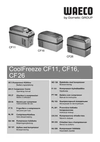
CoolFreeze CFX28, CFX35, CFX40, CFX50, CFX65, CFX65DZ
2
CFX28, CFX35, CFX40 CFX50, CFX65, CFX65DZ
3
4
5
6
CFX50, CFX65, CFX65DZ
7
8
9
10
Please read this operating manual carefully before starting the device. Keep it in a safe place for future reference. If the device is passed on to another person, this operating manual must be handed over to the user along with it.
The manufacturer cannot be held liable for damage resulting from improper usage or incorrect operation.
Contents
1 Explanation of symbols. 28
2 Safety instructions. 29
2.1 General safety 29
3 Scope of delivery 31
4 Accessories 31
5 Intended use 32
6 Function description 33
6.1 Scope of functions 33
6.2 Operating and display elements 34
7 Operation 35
7.1 Before initial use 35
7.2 Energy saving tips 36
7.3 Connecting the cooler 36
7.4 Using the battery monitor 37
7.5 Using the cooler 39
7.6 Setting the temperature 40
7.7 Using the emergency switch (where fitted) 41
7.8 USB port for power supply 41
7.9 Switching off the cooler 41
7.10 Defrosting the cooler 42
7.11 Replacing the device fuse 42
7.12 Replacing the plug fuse (12/24 V) 43
7.13 Replacing the light PCB 43
8 Cleaning and maintenance 44
9 Guarantee 44
10 Troubleshooting. 45
11 Disposal 46
12 Technical data 46
1 Explanation of symbols

DANGER!
Safety instruction: Failure to observe this instruction will cause fatal or serious injury.

WARNING!
Safety instruction: Failure to observe this instruction can cause fatal or serious injury.

CAUTION!
Safety instruction: Failure to observe this instruction can lead to injury.

NOTICE!
Failure to observe this instruction can cause material damage and impair the function of the product.

NOTE
Supplementary information for operating the product.
Action: This symbol indicates that action is required on your part. The required action is described step-by-step.
This symbol describes the result of an action.
Fig. 1 5, page 3: This refers to an element in an illustration. In this case, item 5 in figure 1 on page 3.
2 Safety instructions
2.1 General safety

WARNING!
- Do not operate the device if it is visibly damaged.
- If this device's power cable is damaged, it must be replaced by the manufacturer, customer service or a similarly qualified person in order to prevent safety hazards.
- This device may only be repaired by qualified personnel. Improper repairs can lead to considerable hazards.
- This device can be used by children aged 8 years or over, as well as by persons with diminished physical, sensory or mental capacities or a lack of experience and/or knowledge, providing they are supervised or have been taught how to use the device safely and are aware of the resulting risks.
- Cleaning and user maintenance must not be carried out by children without supervision.
Children must not play with the device.
Children must be supervised to ensure that they do not play with the device. - Always keep and use the device out of the reach of children under the age of 8 years.
- Do not store any explosive substances such as spray cans with a flammable propellant in the device.

CAUTION!
- Disconnect the device from the power supply
- before each cleaning and maintenance
- after every use
- Food may only be stored in its original packaging or in suitable containers.

NOTICE!
-
Check that the voltage specification on the type plate corresponds to that of the energy supply.
-
Only connect the device as follows:
-
With the DC cable to a DC plug socket in the vehicle (e. g. cigarette lighter)
-
Or with the 230 V connection cable to the 230 V AC mains supply
-
Never pull the plug out of the socket by the cable.
- If the cooler is connected to the DC socket: Disconnect the cooler and other power consuming devices from the battery before connecting the quick charging device.
- If the cooler is connected to the DC socket: Disconnect the cooler or switch it off when you turn off the engine. Otherwise, you may discharge the battery.
- The cooling device is not suitable for transporting caustic materials or materials containing solvents.
- The cooling device contains inflammable cyclopentane in the insulation. The gases in the insulation material require special disposal procedures. Deliver the device at the end of its lifecycle to an appropriate recycling.
2.2 Operating the device safely

CAUTION!
- Before starting the device, ensure that the power supply line and the plug are dry.

NOTICE!
- Do not use electrical devices inside the cooler unless they are recommended by the manufacturer for the purpose.
- Do not place the device near naked flames or other heat sources (heaters, direct sunlight, gas ovens etc.).
Danger of overheating!
Ensure at all times that there is sufficient ventilation so that the heat that arises during operation does not build up. Make sure that the device is sufficiently far away from walls and other objects so that the air can circulate.
- Ensure that the ventilation openings are not covered.
- Do not fill the inner container with ice or fluid.
- Never immerse the device in water.
- Protect the device and the cable against heat and moisture.
3 Scope of delivery
The scope of delivery is shown in fig. 1, page 3.
Item Quantity Description
1 1 Cooler
2 1 Connection cable for 12 / 24V = = connection
3 1 Connection cable for 100 - 240V connection
-1 Operating manual
4 Accessories
Available as accessory (not included in scope of delivery):
Designation Item no. Model
Universal fixing kit (belt system) CFX-UFK 9105304041 suits all models
Quick release fixing kit CFX-QFK 9105306218 CFX28 only
Wireless display CFX-WD
9105304042 suits all models
5 Intended use

The cooler is suitable for cooling and freezing foods. The device is also suitable for use on boats.

The device is designed to be operated from a 12V = or 24V = on-board supply socket of a vehicle (e. g. cigarette lighter), boat or caravan as well as from a 100 - 240 V AC mains.
The cooling device is intended to be used in household and similar applications such as
- staff kitchen areas in shops, offices and other working environments
- farm houses
- clients in hotels, motels and other residential type environments
- bed and breakfast type environments
- catering and similar non-retail applications

CAUTION! Health hazard!
Please check if the cooling capacity of the device is suitable for storing the food or medicine you wish to cool.
6 Function description
The cooler can chill products, keep them cool as well as freeze them. A low maintenance refrigerant circuit with compressor provides the cooling. The generous insulation and powerful compressor ensure efficient and fast cooling.
The cooler is portable.
The cooler can withstand a constant heel (inclination) of 30° , for example when used on boats.
6.1 Scope of functions
- Power supply with priority circuit for connecting to the AC mains
- Three-level battery monitor to protect the vehicle battery
- Display with temperature gauge in ° C and ° F switches off automatically at low battery voltage
- Temperature setting: With two buttons in steps of 1° C ( 2° F )
- Foldable carrying handles
- USB port for power supply
Emergency switch (where fitted) - Removable wire basket
6.2 Operating and display elements
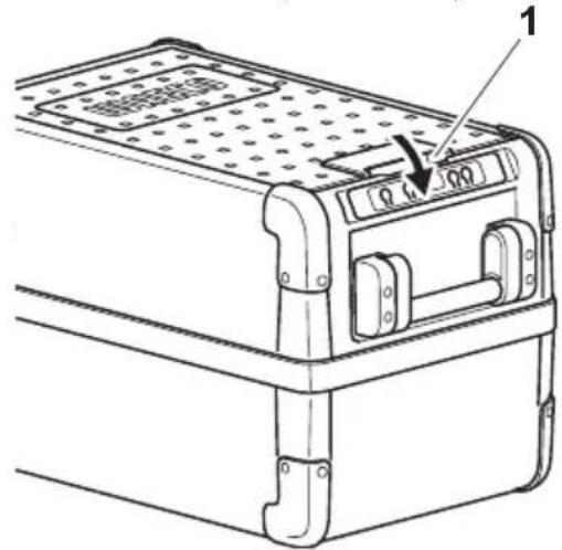
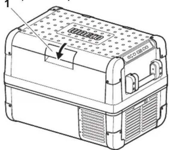
Latch for lid: fig. 2 1, page 3
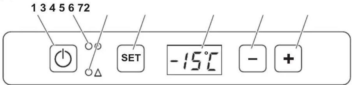
Operating panel (fig. 3, page 3)
| Item Description Explanation | ||
| 1 | ON OFF | Switches the cooler on or off when the button is pressed for between one and two seconds |
| 2 | POWER “○” | Status indication |
| LED lights up green: Compressor is on | ||
| LED lights up orange: Compressor is off | ||
| LED flashes orange: display switched off automatically due to low battery voltage | ||
| 3 | ERROR LED flashes red: Device is switched on but not ready for operation | |
| 4 | SET Selects the input mode - Temperature setting - Celsius or Fahrenheit display - Set battery monitor | |
| 5 | - | Display, shows the information |
| 6 | DOWN - | Press once to decrease the value |
| 7 | UP + | Press once to increase the value |
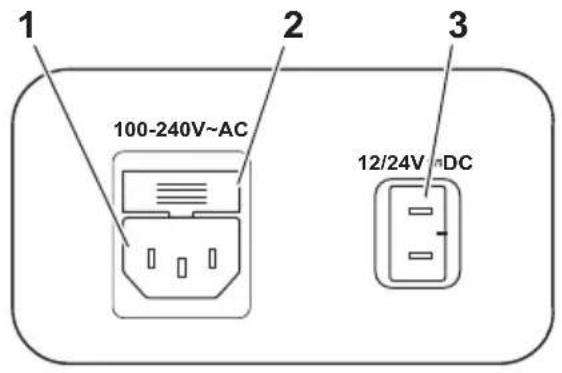
Connection sockets (fig. 4, page 4)
| Item Description |
| 1 Connection socket AC voltage supply |
| 2 Fuse holder |
| 3 Connection socket DC voltage supply |
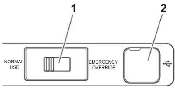
Emergency switch (when fitted) and USB port (fig. 5, page 4)
Item Description
1 Emergency switch
2 USB port for power supply
7 Operation
7.1 Before initial use

NOTE
Before starting your new cooler for the first time, you should clean it inside and outside with a damp cloth for hygienic reasons (please also refer to the chapter "Cleaning and maintenance" on page 44).
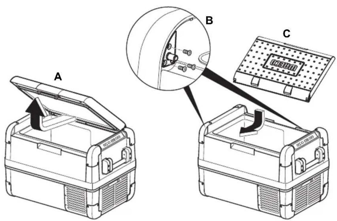
Reversing the lid opening direction
CFX50, CFX65, CFX65DZ
The lid hinges can be moved to the opposite side if you want to open the lid from the opposite direction. To do this, proceed as follows:
Open the lid and remove it (fig. 6 A, page 4).
Remove 3 screws per hinge (fig. 6 B, page 4) and take off hinges.
Remove plastic covers from new hinge positions with a small screwdriver and re-fit to old hinge positions.
Re-fit hinges in new positions.
Insert the lid in the hinges on the opposite side (fig. 6 C, page 4).
Selecting the temperature units
Temperature display units can be switched between Celsius and Fahrenheit as follows:
Switch on the cooler.
Press the "SET" button (fig. 3 4, page 3) twice.
Use the "UP +" (fig. 3 7, page 3) or "DOWN -" (fig. 3 6, page 3) buttons to select Celsius or Fahrenheit.
- The selected temperature units then appear in the display for a few seconds. The display flashes several times before it returns to the current temperature.
7.2 Energy saving tips
- Choose a well ventilated installation location which is protected against direct sunlight.
- Allow warm food to cool down first before placing it in the cooling device to keep cool.
- Do not open the cooling device more often than necessary.
- Do not leave the cooling device open for longer than necessary.
- Defrost the cooler once a layer of ice forms.
- Avoid unnecessarily low temperatures.
7.3 Connecting the cooler
Connecting to a battery (Vehicle or boat)
The cooler can be operated with 12V or 24V =

NOTICE! Danger of damage!
Disconnect the cooler and other consumer units from the battery before you connect the battery to a quick charging device.
Overvoltage can damage the electronics of the device.
For safety reasons the cooler is equipped with an electronic system to prevent the polarity reversal. This protects the cooler against short-circuiting when connecting to a battery.
Plug the 12/24V connection cable (fig. 1 2, page 3) into the device DC voltage socket and also into a 12V or 24V cigarette lighter socket.
Connecting to a 100-240 V AC mains (E.g. in the home or office)

DANGER! Danger of electrocution!
- Never handle plugs and switches with wet hands or if you are standing on a wet surface.
- If you are operating your cooler on board a boat from a mains connection of 100 - 240V , you must install a residual current circuit breaker between the 100 - 240V mains and the cooler.
Seek advice from a trained technician.
The coolers have an integrated multi-voltage power supply with priority circuit for connecting to an AC voltage source of 100-240 V. The priority circuit automatically switches the cooler to mains operation, if the device is connected to a 100-240 V AC mains, even if the 12/24 V connection cable is still attached.
Plug the 100 - 240V connection cable (fig. 3, page 3) into the device AC voltage socket and connect it to the 100 - 240V AC voltage mains.
7.4 Using the battery monitor
The device is equipped with a multi-level battery monitor that protects your vehicle battery against excessive discharging when the device is connected to the on-board 12/24 V supply.
If the cooler is operated when the vehicle ignition is switched off, the cooler switches off automatically as soon as the supply voltage falls below a set level. The cooler will switch back on once the battery has been recharged to the restart voltage level.

NOTICE! Danger of damage!
When switched off by the battery monitor, the battery will no longer be fully charged. Avoid starting repeatedly or operating current consumers without longer charging phases. Ensure that the battery is recharged.
In "HIGH" mode, the battery monitor responds faster than at the levels "LOW" and "MED" (see the following table).
| Battery monitor mode LOW MED HIGH | ||
| Switch-off voltage at 12 V | 10.1 V 11.4 V 11.8 V | |
| Restartvoltage at 12 V | 1 1 . 1 V 1 2 . 2 V 1 2 . 6 V | |
| Switch-off voltage at 24 V | 21.5 V | 24.1 V 24.6 V |
| Restart voltage at 24 V | 23.0 V | 25.3 V 26.2 V |
The battery monitor mode can be selected as follows:
Switch on the cooler.
Press the "SET" button (fig. 3 4, page 3) three times.
Use the "UP +" (fig. 3 7, page 3) or "DOWN -" (fig. 3 6, page 3) buttons to select the battery monitor mode.
√ Digital display will be as follows: Lo (LOW), Nd (MED), Hi (HIGH)
The selected mode then appears in the display for a few seconds. The display flashes several times before it returns to the current temperature.

NOTE
When the cooler is supplied by the starter battery, select the battery monitor mode "HIGH". If the cooler is connected to a supply battery, the battery monitor mode "LOW" will suffice.
7.5 Using the cooler

NOTICE! Danger of overheating!
Ensure at all times that there is sufficient ventilation so that the heat that generated during operation can dissipate. Ensure that the ventilation slots are not covered. Make sure that the device is sufficiently far away from walls and other objects so that the air can circulate.
Place the cooler on a firm foundation.
Make sure that the ventilation slots are not covered and that the heated air can dissipate.

NOTE
Place the cooler as shown (fig. 1, page 3). If you operate the box in a different orientation it can be damaged.
Connect the cooler, see chapter "Connecting the cooler" on page 36.

NOTICE! Danger from excessively low temperature!
Ensure that the only those objects are placed in the cooler that are intended to be cooled at the selected temperature.
Press the "ON/OFF" button (fig. 3 1, page 3) for between one and two seconds.
The LED "O" lights up (fig. 3 2, page 3).
The display (fig. 3 5, page 3) switches on and shows the current cooling temperature.

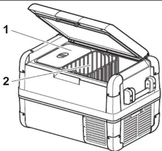
CAUTION! Health hazard!
CFX65DZ:
If the temperature in the freezer compartment (fig. 8 1, page 5) is very low (-22°C) , the temperature range in the cooling department (fig. 8 2, page 5) can be below freezing as well.

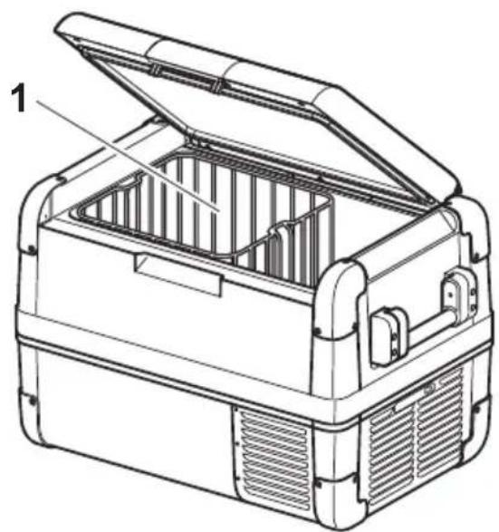
NOTE Displayed temperature
- CFX28, CFX35, CFX40, CFX50, CFX65: The temperature displayed is that of the large interior compartment (e.g. CFX50, CFX65: fig. 7 1, page 5).
-
CFX65DZ:
-
With fridge/freezer divider in: The temperature displayed is that of the freezer compartment (fig. 8 1, page 5).
- With fridge/freezer divider out: The actual compartment temperature will be considerably warmer than the displayed temperature
The cooler starts cooling the interior.

NOTE When operating with the battery, the display switches off automatically if the battery voltage is low. The LED "O" flashes orange.
Latching the cooler lid
Close the lid.
Press the latch (fig. 2 1, page 3) down, until it latches in place audibly.
7.6 Setting the temperature
Press the "SET" button (fig. 3 4, page 3) once.
Use the "UP +" (fig. 3 7, page 3) and "DOWN -" (fig. 3 6, page 3) buttons to select the cooling temperature.
- The cooling temperature appears in the display for a few seconds. The display flashes several times and then the current temperature is displayed again.
7.7 Using the emergency switch (where fitted)
The emergency switch (fig. 5 1, page 4) is located below the control panel on all models except CFX28 where it is located above the power inlet sockets. For normal operation the switch is in the "NORMAL USE" position.
If an electronic control failure occurs, slide the switch to "EMERGENCY OVERRIDE" position

NOTE
If the switch is in the "EMERGENCY OVERRIDE" position, the cooler runs with full cooling capacity and may freeze.
7.8 USB port for power supply
USB port allows you to charge small devices like mobile phones and mp3-players.
To use your cooling box with any USB devices, simply connect a USB cable (not included) to your device.

NOTE
Ensure that any small device connected to the USB port is compatible with 5V / 500mA operation.
7.9 Switching off the cooler
Empty the cooler.
Switch the cooler off.
Pull out the connection cable.
If you do not want to use the cooler for a longer period of time:
Leave the cover slightly open. This prevents odour build-up.
7.10 Defrosting the cooler
Humidity can form frost in the interior of the cooling device or on the evaporator. This reduces the cooling capacity. Defrost the device in good time to avoid this.

NOTICE! Danger of damage!
Never use hard or pointed tools to remove ice or to loosen objects which have frozen in place.
To defrost the cooler, proceed as follows:
Take out the contents of the cooling device.
If necessary, place them in another cooling device to keep them cool.
Switch off the device.
Leave the lid open.
Wipe off the defrosted water.
7.11 Replacing the device fuse

DANGER! Danger of electrocution!
Disconnect the power supply and the connection cable before you replace the device fuse.
Disconnect the power supply to the device.
Pull off the connection cable.
Pry out the fuse insert (fig. 4 2, page 4) with a screwdriver.
Replace the defective glass fuse with a new one that has the same rating (4A 250V).
Press the fuse insert back into the housing.
Reconnect the power supply to the device.
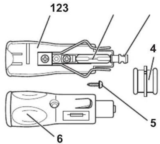
7.12 Replacing the plug fuse (12/24 V)
Pull the adapter sleeve (fig. 9 4, page 5) off of the plug.
Unscrew the screw (fig. 9 5, page 5) out of the upper half of the housing (fig. 9 6, page 5).
Carefully lift the upper half of the housing off from the lower (fig. 9 1, page 5) half.
Take out the contact pin (fig. 9 3, page 5).
Replace the defective fuse (fig. 2, page 5) with a new fuse that has the same rating (8 A).
Re-assemble the plug in the reverse order.
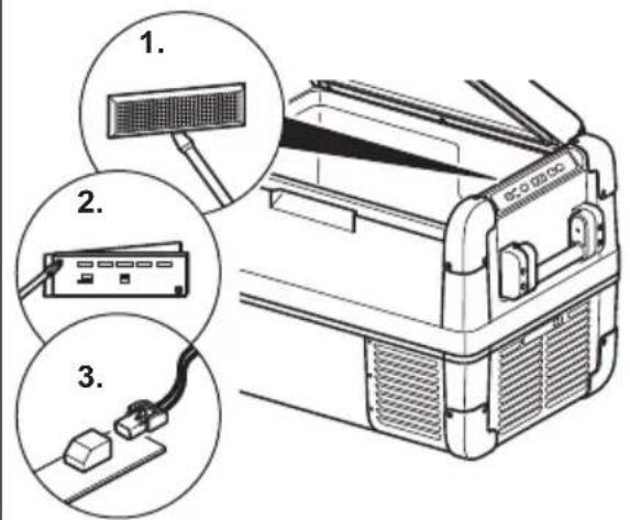
7.13 Replacing the light PCB
Disconnect the power supply to the device.
Pry out the transparent cover with a screwdriver (fig. 10 1, page 5).
Unscrew the PCB mounting screws (fig. 10 2, page 5).
Pull out the plug from the PCB (fig. 10 3, page 5).
Replace the defective light PCB with a new one.
Fit new PCB using reverse of removal instructions.
Press the transparent cover back into the housing.
Reconnect the power supply to the device.
8 Cleaning and maintenance

WARNING!
Always disconnect the device from the power supply before you clean and service it.

NOTICE! Risk of damage
- Never clean the cooler under running water or in dish water.
- Do not use abrasive cleaning agents or hard objects during cleaning as these can damage the cooler.
Occasionally clean the device interior and exterior with a damp cloth.
Make sure that the air inlet and outlet vents on the device are free of any dust and dirt, so that heat can be released and the device is not damaged.
9 Guarantee
The statutory warranty period applies. If the product is defective, please contact the manufacturer's branch in your country (see the back of the instruction manual for the addresses) or your retailer.
For repair and guarantee processing, please include the following documents when you send in the device:
A copy of the receipt with purchasing date
A reason for the claim or description of the fault
10 Troubleshooting
Fault Possible cause Suggested remedy
| Device does not func-tion, LED does not glow. | There is no voltage pres-ent in the 12/24 V socket(cigarette lighter) in your vehicle. | The ignition must be switched on in most vehicles to apply current to the cigarette lighter. |
| No voltage present in the AC voltage socket. | Try using another plug socket. | |
| The device fuse is defec-tive. | Replace the device fuse, see chapter “Replacing the device fuse” on page 42. | |
| The integrated mains adapter is defective. | This can only be repaired by an authorised repair centre. | |
| The device does not cool (plug is inserted, “POWER” LED is lit). | Defective compressor. This can only be repaired by an authorised customer services unit. | |
| The device does not cool (plug is inserted, “POWER” LED flashes orange, display is switched off). | Battery voltage is too low. | Test the battery and charge it as needed. |
| When operating from the 12/24 V socket (cigarette lighter): The ignition is on and the device is not working and the LED is not lit. Pull the plug out of the socket and make the following checks. | The cigarette lighter socket is dirty. This results in a poor elec-trical contact. | If the plug of your cooler becomes very warm in the cigarette lighter socket, either the lighter socket must be cleaned or the plug has not been assembled correctly. |
| The fuse of the 12/24 V plug has blown. | Replace the fuse (8 A) in the 12/24 V plug, see chapter “Replacing the plug fuse (12/24 V)” on page 43. | |
| The vehicle fuse has blown. | Replace the vehicle’s 12/24 V socket fuse (usually 15 A). Please refer to your vehi-cle’s operating manual. | |
| The display shows an error message (e.g. “Err1”) and the appli-ance does not cool. | The appliance has switched off due to an internal fault. | This can only be repaired by an authorised repair centre. |
11 Disposal
Place the packaging material in the appropriate recycling waste bins wherever possible.

If you wish to finally dispose of the product, ask your local recycling centre or specialist dealer for details about how to do this in accordance with the applicable disposal regulations.
12 Technical data
| CFX28 CFX35 CFX40 | |||
| Item no.: 9105305970 9 | 105304047 9105304048 | ||
| Connection voltage: | 12/24 V--- and 100-240 V~ | ||
| Rated current: | 12 V---: 6.5 A | 12 V---: 7.0 A | |
| 24 V---: 3.2 A | 24 V---: 3.2 A | ||
| 100 V~: 0.75 A | 100 V~: 0.86 A | ||
| 240 V~: 0.32 A | 240 V~: 0.42 A | ||
| Cooling capacity: | +10 °C to -22 °C (+50 °F to -8 °F) | ||
| Category: 1 | |||
| Energy efficiency class: | A++ A++ | ||
| Energy consumption: | 61 kWh/annum | 62 kWh/annum | 64 kWh/annum |
| Gross volume: | 28 I | 34.5 I | 41 I |
| Storage volume: | 26 I | 32 I | 38 I |
| Climate class: | N, T | ||
| Ambient temperature: | +16 °C to +43 °C | ||
| Noise emission: | 34 dB(A) | 45 dB(A) | |
| USB: | 5 V---, 500 mA | ||
| Dimensions (W x H x D) in mm (including handles): | 620 x 425 x 342 | 692 x 411 x 398 | 692 x 461 x 398 |
| Weight: | 13 kg | 17.5 kg | 18.5 kg |
| CFX50 CFX65 | CFX65DZ | ||
| Item no.: 9105304049 9 | 105304050 9105304051 | ||
| Connection voltage: | 12/24 V= and 100-240 V~ | ||
| Rated current: | 12 V=: 7.8 A | 12 V=: 8.2 A | 12 V=: 5.5 A |
| 24 V=: 3.6 A | 24 V=: 3.8 A | 24 V=: 2.6 A | |
| 100 V~: 0.95 A | 100 V~: 1.0 A | 100 V~: 0.75 A | |
| 240 V~: 0.46 A | 240 V~: 0.48 A | 240 V~: 0.37 A | |
| Cooling capacity: | +10 °C to -22 °C (+50 °F to -8 °F) | ||
| Category: 1 | |||
| Energy efficiency class: | A++ A+ | ||
| Energy consumption: | 66 kWh/annum | 69 kWh/annum | 115 kWh/annum |
| Gross volume: 50 l 65 l | with divider: 61 l | without divider: 65 l | |
| Storage volume: | 46 l | 60 l | 53 l |
| Climate class: | N, T | ||
| Ambient temperature: | +16 °C to +43 °C | ||
| Noise emission: | 45 dB(A) | ||
| USB: | 5 V=, 500 mA | ||
| Dimensions (W x H x D) in mm (including handles): | 725 x 471x 455 | 725 x 561 x 455 | 725 x 561 x 455 |
| Weight: | 20.4 kg | 22.3 kg | 23.2 kg |

NOTE
If the ambient temperature is above +32°C (+90°F) , the minimum temperature cannot be attained.
Test/certificates:


The coolant circuit contains R134a.
- CFX28, CFX35, CFX40, CFX50, CFX65 :
- CFX28, CFX35, CFX40, CFX50, CFX65:
La temperatura indica se refiere al compartmento grande de refrigeracion y de congelacion (fig. 7 1, pagina 5).
- CFX28, CFX35, CFX40, CFX50, CFX65:
- CFX28, CFX35, CFX40, CFX50, CFX65:
7.6 Stalla in temperature
PASS PÀ! Fare for overopbehing!
- CFX28, CFX35, CFX40, CFX50, CFX65:
7.6 Stille inn temperature
Trykk pà tasten «SET» (fig. 3 4, side 3) én gang.
- CFX28, CFX35, CFX40, CFX50, CFX65:
- CFX28, CFX35, CFX40, CFX50, CFX65:
- CFX28, CFX35, CFX40, CFX50, CFX65:
OTo6paKaemaj TemnepaTypa OTHOCNTcK 60JbUoXoJIoDInIbHO-MOpO3NJIbHOJ Kamepe (pnc.71, cTp.5).
-
CFX65DZ:
-
C neperopokon B xolodnIbHO-Mopo3nIbHO Kamepe: OTo6paKaemay Tempeatypa OTHOCNTcK Mopo3nIbHO Kamepe (pnc. 8 1, ctp. 5).
- Be3 neperopokn B xoJIoNJIbHO-Mopo3IbHOJ Kamepe: DeiCTBNTbHaj Tempeatypa B Kamepe MoKeT HeCKOJIbKO OTIIuATbcra OT OTo6paXaEMoJ Tempepatpybl.
XoIodnIbHnK HaunHaet OxJaDaTb BHyTpEHHee npoctpaHCTBO.

YKA3AHNE
Ipn pa6ote ot akkymyIaTOPHOb 6aTapeu DnCnIe n ABToMaTuYeCKN OTKJIouHaETcR, ecn HAnpJxKeHne 6aTapeu CTAHOBNTc R CnUKOM Hn3KIM. CBeToOnoD «O» MInraE T opAHXeBBiM CBETOM.
Блорвкхолдьнka
3aKpoIe KpbIwKy.
HajimaTe Ha 3aueKky Bn3 (pnc. 2 1, ctp. 3), noka oHa rpoMko He 3aueJKNHeTcra Ha MeCTe.
7.6 Hac tropona TempepaTpybl
HaxmTe KhoNky «SET» (pnc. 3 4, ctp. 3) oIN pa3.
HactpoIte KhoIkoN «UP +» (pnc. 3 6, cTp. 3) nIIN «DOWN -» (pnc. 3 7, cTp. 3) TempeTpy oxJaXdEHHa.
Ha dincnpee Ha HeckoIbKO CekyHd NOBnEeTcH HAcTpoEHnA TeMnepa-typa OxJaXeHnA. DIncnpeM MiRaet HeckoIbKO pa3, npeJde Yem BepHyTbcra K OTo6paXeHnIO TekuIeN TeMnepaTypbl.
7.7 Исторын eварийHoro nepeknioyateя (ecn BCTpoeH)
Bo Bcex MoeJx, 3a NckIoueHnem CFX28, abapnHbB bblKIOuataJIb (pnc. 5 1, ctp. 4) haxoINTcno PaHeJIbU ynpabLeHnB. B CFX28 abapnHbB bIKIOuATJIb HaxoINTcHaD CoeHNHTeJIbHbIMn pa3beMaMn. IJa HopMaJIbHOrO peXIma nepeKIOuATJIb HaxoINTcB nIoJKeHnN «NORMAL USE» (hopMaJIbHOe nCNoJIb3OBaHne).
Пи HeICnpaBHOCTn 3JIeKtpoHHOrO ynpaBHeHЯ NOdBnHbTe BbIKIHOaTeNb B noJoxeHne «EMERGENCY OVERRIDEDE».

YKA3AHNE
EcnnepeeknouateIb haoDntcB noLoxKeHn «EMERGENCY OVERRIDE》,xoIoOnJIbHnk pa6oTaET Ha noIHOm MOUHOCTN OXJaXdEHHa.
7.8 Iopr USB dIy 3neKtpoCha6xehnra
IopT USB no3B0JareT 3apjXaTb MaIbIe yCTpoiCTBa TnIa MO6NJIbHbIX TeJe-foHOB n mp3-nIeepoB.
7.13 3aMeHa CBeTOBOI neaTHOIIaTbI
OTcoeHHTe 3JIeKTPoNTaHne OT np6opa.
BbInbTe npo3paHoe nokpbItne c nOMOu bIO OTBeptkn (pnc. 10 1, ctp. 5).
OTBepHnTe KpeNexKhIe BnHTbI neaTHoI nlaTbI (pnc. 10 2, ctp. 5).
BbInbTe wTeNceIb n3 neaTHoI pTaBi (pnc. 10 3, cTp. 5).
3aMeHnTe HEnCnpabHyIO CBeTOByIO neaTHyIO PnATy HOBOI.
YCTaHOBInTe HOByIO neaTHyIO pAty, DeiCTByB O6paTHOM nopAKe.
BCTaBbTe npo3paHoe nokpbItne o6paTHO B KOpNyc.
ПрсоeДиHITe 3JIeKTPoNTaHne K np6Opy.
8 Ynctka n yxoid

ПЕДУПЕЖДEHNE!
Ipeed uicTKoH uyOdom Bcerda oTcoeHNyTe np6op ot cetn.

BHIMAHHE! Onachocmb nopejdeHua!
- Kateropnueckn 3anpeaetcya nctntb npnbop noi ctpyei BOdbI INI DaKe B eMKoCTN C BODoI.
He nCnoIb3yIte IJn yNCTKn a6pa3NBhIe YNCTaIue cpeIcTBA IIIN OCTpIe IpeDMeTBI, T. K. OHN MOrY T pNBeCTN K NOBpeXdEHHaM XOJODINbHnKa.
Пернодунесян очшайтприбор саржи и n3HyTpN Влжно Тряпков.
Y6eI NTecb B TOM, yTO npITouHO-BbITJXHbIE BEHTINJauOHHbIE OTBepCTN OUHSeHbI OT nbIIM 3aIrp3HeHn, yTO6bl MOxHO 6blIO OTBECTN BO3-HNKaIOoOee npi pa6ote TeIIO n IpeIoTbpaTb OnaCHOCTb NOBpeKdEHHa np6oba.
9 rapaHTnA
IIO BO3MOXHOCTN, BbIKnIbIbAaTe yNaKOBOuHbI MaTePnaJ B MyCop, NOJIeKaUIM BTOpUHOn Nepepa6oTke.
EcnBbIOkOHaTeIbHO BbIBOAnTe npOdyKT n3 3KcIIyatauN,TO
noIyHTe INΦopMaunIO B6nJkaIwem ZeHTpe NO BTOpHNo
nepepaBOTke IIN B TOPBOO Bin O COOTBeTCTByUx
npedncaHnx no yTNIn3aun.
12 Texnueckne daHHbIe
Ovladaci panel (obr. 3, strana 3)
- CFX28, CFX35, CFX40, CFX50, CFX65:
Ovladaci panel (obr. 3, strane 3)
Pol. Označenie Vysvetlenie
- CFX28, CFX35, CFX40, CFX50, CFX65
Dometic Australia Pty. Ltd.
1 John Duncan Court
Varsity Lakes QLD 4227
1800212121
+61755076001
Mail: sales@dometic-waeco.com.au
AUSTRIA
Dometic Austria GmbH
Neudorferstraße 108
A-2353 Guntramsdorf
+43 2236 908070
+43223690807060
Mail: info@dometic.at
BENELUX
Dometic Branch Office Belgium
Zincstraal 3
B-1500 Halle
+32 2 3598040
+3223598050
Mail: info@dometic.be
BRAZIL
Dometic DO Brasil LTDA
Avenida Paulista 1754, conj. 111
SP 01310-920 Sao Paulo
+551132513352
+551132513362
Dometic Group Asia Pacific
Suites 2207-11·22/F·Tower 1
The Gateway 25 Canton Road
Tsim Sha Tsui·Kowloon
+85224611386
+85224665553
Mail: info@waeco.com.hk
HUNGARY
Dometic Zrt. Sales Office
KerekgyarTo u.5.
H-1147 Budapest
+3614684400
+3614684401
Domatic Italy S.r.l.
Via Virgilio, 3
1-47122 Forli (FC)
+390543754901
+390543754983
Mail: vendite@dometic.it
JAPAN
Dometic KK
Maekawa-Shibaura,Bldg.2
2-13-9 Shibaura Minato-ku
Tokyo 108-0023
+81354453333
+81354453339
Mail: info@dometic.jp
MEXICO
Domatic Mx, S. de R. L. de C. V.
Circuito Médicos No. 6 Local 1
Colonia Ciudad Satélite
CP 53100 Naucalpan de Juarez
Estado de Mexico
+52553744108
+525553934683
Mail: info@dometic.com.mx
NETHERLANDS
Dometic Benelux B.V.
Ecustraat 3
NL-4879 NP Etten-Leur
+31765029000
+31765029019
Mail: info@dometic.nl
NEW ZEALAND
Dometic New Zealand Ltd.
Unite E, The Gate
373 Neilson Street
Penrose 1, Auckland
+6496221490
+6496221573
Mail: customerservices@dometic.co.nz
NORWAY
Dometic Norway AS
Osteroyveien 46
N-3232 Sandefjord
+4733428450
+4733428459
Mail: firmpost@dometic.no
POLAND
Dometic Poland Sp. z o.o.
Ul. Puławska 435A
PL-02-801 Warszawa
+48224143200
+48224143201
Mail: info@dometic.pl
PORTUGAL
Dometic Spain, S.L.
Komsomolskaya square 6-1
RU-107140 Moscow
+74957807939
+74959165653
Mail: info@dometic.ru
SINGAPORE
Dometic Pte Ltd
18 Boon Lay Way 06-140 Trade Hub 21
Singapore 609966
+6567953177
+6568626620
Mail: dometic@dometic.com.sg
SLOVAKIA
Dometic Slovakia s.r.o. Sales Office Bratislava
Nadražna 34/A
900 28 Ivanka pri Dunaji
/241245529680
Mail: bratislava@dometic.com
SOUTH AFRICA
Domatic (Pty) Ltd.
Regional Office
South Africa & Sub-Saharan Africa
2 Avalon Road
West Lake View Ext 11
Modderfontein 1645
Johannesburg
+27114504978
+27114504976
Mail: info@dometic.co.za
SPAIN
Dometic Spain S.L.
Ayda, Sierra del Guadarrama, 16
E-28691 Villanueva de la Canada
Madrid
+34902111042
+34 900 100 245
Mail: info@dometic.es
SWEDEN
Dometic Scandinavia AB
Gustaf Melins data 7
Dometic Switzerland AG
Riedackerstrasse 7a
CH-8153 Rümlang
+41448187171
+41448187191
Mail: info@dometic.ch
UNITED ARAB EMIRATES
Dometic Middle East FZCO
P.O.Box 17860
S-D 6, Jebel Ali Freezone
Dubai
+97148833858
+97148833868
Mail: info@dometic.ae
UNITED KINGDOM
Dometic UK Ltd
Dometic House, The Brewery
Blandford St. Mary
DorsetDT119LS
+443446260133
+443446260143
Mail: customerservices@dometic.co.uk
USA
Dometic RV Division
1120 North Main Street
Elkhart, IN 46515
+1574-264-2131
- COOLFREEZE CFX28, CFX35, CFX40, CFX50, CFX65, CFX65DZ
- CONTENTS
- 1 EXPLANATION OF SYMBOLS
- DANGER
- WARNING
- CAUTION
- NOTICE
- NOTE
- 2 SAFETY INSTRUCTIONS
- 2.1 GENERAL SAFETY
- 2.2 OPERATING THE DEVICE SAFELY
- 3 SCOPE OF DELIVERY
- ITEM QUANTITY DESCRIPTION
- 4 ACCESSORIES
- DESIGNATION ITEM NO. MODEL
- 5 INTENDED USE
- CAUTION! HEALTH HAZARD
- 6 FUNCTION DESCRIPTION
- 6.1 SCOPE OF FUNCTIONS
- 6.2 OPERATING AND DISPLAY ELEMENTS
- CONNECTION SOCKETS (FIG. 4, PAGE 4)
- ITEM DESCRIPTION
- 7 OPERATION
- 7.1 BEFORE INITIAL USE
- REVERSING THE LID OPENING DIRECTION
- SELECTING THE TEMPERATURE UNITS
- 7.2 ENERGY SAVING TIPS
- 7.3 CONNECTING THE COOLER
- CONNECTING TO A BATTERY (VEHICLE OR BOAT)
- NOTICE! DANGER OF DAMAGE
- CONNECTING TO A 100-240 V AC MAINS (E.G. IN THE HOME OR OFFICE)
- DANGER! DANGER OF ELECTROCUTION
- 7.4 USING THE BATTERY MONITOR
- 7.5 USING THE COOLER
- NOTICE! DANGER OF OVERHEATING
- NOTICE! DANGER FROM EXCESSIVELY LOW TEMPERATURE
- CFX65DZ
- NOTE DISPLAYED TEMPERATURE
- LATCHING THE COOLER LID
- 7.6 SETTING THE TEMPERATURE
- 7.7 USING THE EMERGENCY SWITCH (WHERE FITTED)
- 7.8 USB PORT FOR POWER SUPPLY
- 7.9 SWITCHING OFF THE COOLER
- 7.10 DEFROSTING THE COOLER
- 7.11 REPLACING THE DEVICE FUSE
- 7.12 REPLACING THE PLUG FUSE (12/24 V)
- 7.13 REPLACING THE LIGHT PCB
- 8 CLEANING AND MAINTENANCE
- NOTICE! RISK OF DAMAGE
- 9 GUARANTEE
- 10 TROUBLESHOOTING
- 11 DISPOSAL
- 12 TECHNICAL DATA
- 7.6 STALLA IN TEMPERATURE
- PASS PÀ! FARE FOR OVEROPBEHING
- 7.6 STILLE INN TEMPERATURE
- YKA3AHNE
- БЛОРВКХОЛДЬНKA
- 7.6 HAC TROPONA TEMPEPATPYBL
- 7.7 ИСТОРЫН EВАРИЙHORO NEPEKNIOYATEЯ (ECN BCTPOEH)
- 7.8 IOPR USB DIY 3NEKTPOCHA6XEHNRA
- 7.13 3AMEHA CBETOBOI NEATHOIIATBI
- 8 YNCTKA N YXOID
- ПЕДУПЕЖДEHNE
- BHIMAHHE! ONACHOCMB NOPEJDEHUA
- 9 RAPAHTNA
- 12 TEXNUECKNE DAHHBIE
- POL. OZNAČENIE VYSVETLENIE
- AUSTRIA
- BENELUX
- BRAZIL
- HUNGARY
- JAPAN
- MEXICO
- NETHERLANDS
- NEW ZEALAND
- NORWAY
- POLAND
- PORTUGAL
- SINGAPORE
- SLOVAKIA
- SOUTH AFRICA
- SPAIN
- SWEDEN
- UNITED ARAB EMIRATES
- UNITED KINGDOM
- USA
Brand : WAECO
Model : CoolFreeze CFX 28
Category : Fridge