
CoolMatic MDC50 - Fridge WAECO - Free user manual and instructions
Find the device manual for free CoolMatic MDC50 WAECO in PDF.

| Product type | Compression refrigerator-freezer |
| Brand | WAECO |
| Model | CoolMatic MDC50 |
| Intended use | Camping, boat, leisure (permanent heeling angle 30° max) |
| Power supply | 12V/24V DC (battery) or 230V AC with optional rectifier |
| Total capacity | 43 liters |
| Freezer capacity | 4 liters |
| Refrigerator temperature range | +2°C to +10°C |
| Freezer temperature range | 0°C to -18°C |
| Dimensions (W x H x D) | 425 x 620 x 445 mm |
| Weight | 15 kg |
| Average power consumption | 45 W |
| Electronic protection | Reverse polarity, short-circuit, automatic shutdown in case of low voltage |
| Temperature regulator | Yes, continuous adjustment from min (warm) to max (cold) |
| Locking system | 3 positions: transport, closed, ventilation |
| Door opening side change | Yes, possible on right or left |
| Customizable front panel | Yes, removable and replaceable |
| Compressor | Yes, overvoltage protection |
| Refrigerant | R134a |
| Certifications | Compliant with ErP/EuP directive |
| Maintenance | Cleaning with damp cloth, regular manual defrosting |
| Supplied accessories | Mounting set for door reversal, instruction manual |
| Optional accessories | Rectifier MOBITRONIC EPS-100W or MPS-35 for 230V |
Frequently Asked Questions - CoolMatic MDC50 WAECO
User questions about CoolMatic MDC50 WAECO
0 question about this device. Answer the ones you know or ask your own.
Ask a new question about this device
Download the instructions for your Fridge in PDF format for free! Find your manual CoolMatic MDC50 - WAECO and take your electronic device back in hand. On this page are published all the documents necessary for the use of your device. CoolMatic MDC50 by WAECO.
USER MANUAL CoolMatic MDC50 WAECO
We will be happy to provide you with further information about WAECO products. Please order our free catalogue with no obligation to buy on our homepage: www.domatic-waeco.com
F
Please read this operating manual carefully before starting the device. Keep it in a safe place for future reference. If the device is resold, this operating manual must be handed over to the purchaser along with it.
Contents
1 Notes on using the operating manual 22
2 Safety instructions 23
3 Intended use 24
4 Scope of delivery 25
5 Technical description 25
6 Setting up and connecting the cooling device 26
7 Operation 30
8 Cleaning and maintenance 33
9 Guarantee 33
10 Disposal 33
11 Troubleshooting 34
12 Technical data 36
1 Notes on using the operating manual
The following symbols are used in this operating manual:

Caution!
Safety instruction: failure to observe this instruction can cause injury or damage the device.
Caution!
Safety instruction relating to a danger from an electrical current or voltage. Failure to observe this instruction can damage the device and impair its function and cause injury.

Note
Supplementary information for operating the device.
Action: this symbol indicates that action is required on your part. The required action is described step-by-step.
This symbol indicates the result of an action.
fig. 2 1, page 3: this refers to an element in an illustration. In this case, item 1 in figure 2 on page 3.
Please observe the following safety instructions.
2 Safety instructions

Caution!
WAECO International will not be held liable for claims for damage resulting from the following:
- Damage to the device resulting from mechanical influences and overvoltage
- Alterations to the device made without the explicit permission of WAECO International
- Use for purposes other than those described in the operating manual
2.1 General safety

- Have a trained technician make installations in wet rooms.
- This device may only be repaired by qualified personnel. Inadequate repairs can lead to considerable hazards. Should your device need to be repaired, please contact WAECO customer services.
- Do not open the refrigerant circuit under any circumstances.
- Set up the device in a dry location where it is protected against splashing water.
- Do not place the device near naked flames or other heat sources (heaters, direct sunlight, gas ovens etc.)
- If you connect your refrigerator to a battery, please remember that the battery contains acid.
- Ensure that the ventilation slots are not covered.
- The cooling device is not suitable for transporting caustic materials or materials containing solvents.
- Electronic devices are not toys! Always keep and use the device out of the reach of children.
- Food may only be stored in its original packaging or in suitable containers.
- Before starting up the device for the first time, check whether the operating voltage and the battery voltage correspond (see type plate).
- Danger of fatal injuries!
When using the device on boats: if the device is powered by the mains, ensure that the power supply has a ground fault interrupter circuit.
- If the connection cable is damaged, it must be replaced to prevent possible electrical hazards. Only replace a damaged connection cable with a connection cable of the same type and specifications.
2.2 Operating the device safely

- Do not place any electrical devices inside the refrigerator.
- Defrost the device in good time to save energy.
- If you connect the device to a battery, make sure that food does not come into contact with the battery acid.
- Protect the device against rain and moisture.
- Disconnect the cooling device and other power consuming devices from the battery before connecting the battery to a quick charging device.
Overvoltage can damage the electronics of the device.
Note:
Disconnect the device if you are not going to use it for a long time.
- Danger of fatal injuries!
Do not touch exposed cables with your bare hands. This especially applies when operating the device with an AC mains power supply.
3 Intended use
The refrigerator is suitable for cooling and freezing foodstuffs. The device is also suitable for use on boats.

If you wish to cool medicines, please check if the cooling capacity of the device is suitable for the medicine in question.
4 Scope of delivery
Quantity Description
1 R e f r i g e r a t
1 Assembly kit for changing the door hinge
1 Operating manual
4.1 Accessory
If you wish to operate the cooling device with a 230 V AC mains supply, please use one of the following rectifiers:
Description Item number
MOBITRONIC rectifier EPS-100W
MOBITRONIC rectifier MPS-35
5 Technical description
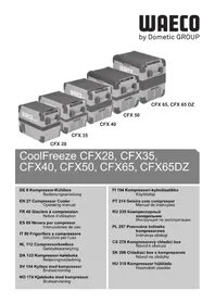
COOLMATIC MDC series refrigerators are suitable for use with a 12 V or 24 V DC voltage and can therefore also be used for camping or on boats. You can also use the MOBITRONIC EPS-100W and MPS-35 rectifiers to connect them to a 230 V mains supply.
The refrigerator can chill products and keep them cool. Products can be deep-frozen in the freezer compartment.
You can use the continuously variable thermostat to set the desired temperature.
All materials used in the refrigerator are compatible for use with foodstuffs. The refrigerant circuit is maintenance-free.
When used on boats the refrigerator can be subjected to a constant inclination of 30^ .
5.1 Operating and display elements
No. in
fig. 1, Explanation
page 3
1 Temperature controller
2 Error code LED
3 Operating panel with ventilation slots (only MDC-90 and MDC-110)
Error codes in the error code LED, see chapter "Troubleshooting" on page 34.

On the MDC-90 and MDC-110 models the temperature control and the error code LED are on the device operating panel. On the MDC-50 and MDC-65 models, the temperature control and the LED are integrated in the device.
6 Setting up and connecting the cooling device
6.1 Setting up the cooling device
The device is designed for ambient temperatures between +16^ and +32^ . In continuous operation, the air humidity may not exceed 90% .
Set up the cooling device in a dry, sheltered place. Avoid placing it near heat sources such as radiators, gas ovens or hot water pipes. Do not let it stand in the direct, strong sunlight.
The cooling device must be positioned so that heated air can dissipate easily. Therefore make sure there is adequate ventilation (fig. 2, page 4).
No. in
fig. 2,
page 4
Explanation
1 Hot waste air
2 Cold intake air
3 Condenser
4 With cover panel 50~mm above
6.2 Sealing system
The cooling device has a locking mechanism to protect it during transport. The following settings are possible:
- Position 1 (transport lock): (fig. 3 1, page 4) The door is locked and secured. To open the door, turn the bolt to position 2.
- Position 2 (releasing transport lock): (fig. 3 2, page 4) The door can be opened.
- Position 3 (VENT position): (fig. 3 3, page 4) The door is slightly open, but fixed in position. Use this position, for example, if you are not going to use the device for a long time.
6.3 Changing the door hinge
You can also change the hinge of the door, so that it opens to the left rather than the right.
To change the door hinge, proceed as follows (fig. 4, page 5):
Remove the upper door hinge (fig. 4 1, page 5).
Carefully lift out the door.
Remove the threaded pins (fig. 4 2, page 5).
Pull the locking hook (fig. 4 3, page 5) off the rod.
Remove the locking plate (fig. 4 4, page 5) and fit it on the opposite side.
Pull the rod downwards and out and put it in the other side.
Fasten the locking hook (fig. 4 3, page 5) back on the rod.
Detach the top and bottom lock holders (fig. 4 5, page 5) on the left side.
Detach the top and bottom door hinges (fig. 4 1, page 5) on the right side.
Fasten the top and bottom door hinges (fig. 4 1, page 5) to the left side.
Fasten the top and bottom lock holders (fig. 4 5, page 5) to the left side.
6.4 Changing the decorative plate
You can change the decorative plate on your cooling device to improve the appearance.
This is how to change the decorative plate:
Remove the screws 1 and 3 (fig. 5 1 and 3, page 5).
Remove components 2 and 4 (fig. 5 2 and 4, page 5).
Pull down the old decorative plate out of the door frame.
Caution: there is a risk of injury!
Put the new decorative plate in the door frame.
Fit the components 2 and 4 (fig. 5 2 and 4, page 5) back on the device.
Fasten the screws 1 and 3 (fig. 5 1 and 3, page 5).
6.5 Connecting the cooling device
For the electrical connection you also need the wiring diagram (fig. 6, page 5).
No. in fig. 6, Meaning page 5
1 Electronic terminal rail
2 Compressor
3 Temperature controller
Cable colours:
No. in fig. 6, Meaning page 5
bl Blue br Brown
Connecting to a battery
The cooling device can be operated with a 12 V or 24 V DC voltage supply.
To avoid voltage loss and therefore a drop in performance, the cable should be kept as short as possible and should not be interrupted if this is possible.
For this reason avoid additional switches, plugs or power strips.
Determine the required cross section of the cable in relation to the cable length according to fig. 7, page 5.
Key for fig. 7, page 5
| Co-ordinate axis Meaning Unit | ||
| I Cable length m | ||
| ØCable cross section mm2 | ||
Caution!
Make sure that the polarity is correct.
- Before starting up the device for the first time, check whether the operating voltage and the battery voltage correspond (see type plate).
Connect the cooling device
- As directly as possible to the pole of the battery or
- To a plug socket which is fused with at least 15 A (at 12 V) or 7.5 A (at 24 V).
Caution!
Disconnect the cooling device and other power consuming devices from the battery before connecting the battery to a quick charging device.
Overvoltage can damage the electronics of the device.
The cooling device is equipped with an electronic device to protect against reversing the polarity and short circuits when connecting to a battery.
To protect the battery, the cooling device switches off automatically if the voltage is insufficient (see table below).
| 12 V 24 V | ||
| Switch-off voltage | 10.4 V 22.8 V | |
| Switch-on voltage | 11.7 V | 24.2 V |
Connecting to 230 V mains supply

Danger of fatal injuries!
Never handle plugs and switches with wet hands or if you are standing in a puddle.
If you are operating your cooling device on board a boat with a mains connection of 230V from the land, you must install a ground protection circuit breaker between the 230V mains supply and the cooling device.
Seek advice from a trained technician.
To operate the cooling device with a 230V mains supply, use an EPS-100 W or MPS-35 MOBITRONIC rectifier.
7 Operation

Before starting your new cooling device for the first time, you should clean it inside and outside with a damp cloth for hygienic reasons (please also refer to the chapter "Cleaning and maintenance" on page 33).
7.1 Energy saving tips
- Choose a well ventilated installation location which is protected against direct sunlight.
- Allow food to cool down first before placing it in the device.
- Do not open the cooling device more often than necessary.
- Do not leave the door open for longer than necessary.
- Defrost the cooling device as soon as a layer of ice forms.
- Avoid unnecessarily low temperatures.
- Clean the condenser of dust impurities at regular intervals.
7.2 Using the cooling device
The cooling device conserves fresh foodstuffs. The freezer compartment conserves frozen foodstuffs and freezes fresh foodstuffs.

Caution!
Ensure that food or liquids in glass containers are not excessively refrigerated.
Liquids expand when they freeze and can thus destroy the glass containers.
Switch the cooling device on by turning the knob (fig. 1 A, page 3) to the right.

After switching on, the cooling device requires approx. 60 s until the compressor starts up.

Caution!
Ensure that the objects placed in the cooling device are suitable for cooling to the selected temperature.
Setting the temperature
You can set the temperature to any level using the knob. The built-in temperature control regulates the temperature as follows:
- min. (left limit) = warmest setting
- max. (right limit) = coldest setting

The cooling capacity can be influenced by:
The ambient temperature
The amount of food to be conserved
The frequency with which the door is opened
Conserving foodstuffs
You can conserve foodstuffs in the cooling device compartment. The time for which the food can be conserved in this way is usually stated on the package.

Caution!
Do not conserve warm food in the cooling device compartment. Do not place glass containers with liquid in the freezer compartment.

Food which can easily absorb tastes and odours and liquids and products with a high alcohol content should be conserved in airtight containers.
The cooling device compartment is divided in different zones with different temperatures:
- The colder zones are immediately over the base, near the back wall.
- Observe the temperature information and best before date on the food packaging.
Observe the following when using the device: -
Do not re-freeze products which are defrosting or have been defrosted, consume them as soon as possible.
-
Wrap food in aluminium foil or cling film and shut it in a suitable box with a lid. This ensures that aromas, the shape and the freshness are better conserved.
Securing the refrigerator door
You can prevent the refrigerator door from being opened inadvertently.
Put the locking mechanism on the top of the door to position 1
(fig. 3 1, page 4).
Defrosting the cooling device
Humidity can form frost in the interior of the cooling device or on the vaporiser. This reduces the cooling capacity. Defrost the device in good time to avoid this.

Caution!
Never use hard or pointed tools to remove ice or to loosen objects which have frozen in place.
To defrost the cooling device, proceed as follows:
Take out the contents of the cooling device.
Place them in another cooling device to keep them cool, if necessary.
Set the knob to 0.
Leave the door open.
Wipe off the water resulting from defrosting or – if present – empty the collecting tray. If your device has a water drain, drain the thawed water off.
Switching off and storing the cooling device
If you do not intend to use the cooling device for a long time, proceed as follows:
Turn the knob to 0.
Disconnect the power cable from the battery or pull the DC cable plug out of the rectifier.
Clean the cooling device (see chapter "Cleaning and maintenance" on page 33).
Leave the lid or door open for to avoid unpleasant odours building up.
Put the lock in the VENT position. This prevents odours from building up.
8 Cleaning and maintenance

Caution!
Do not use abrasive cleaning agents or hard objects during cleaning as these can damage the cooling device.

Caution!
Never use brushes, scouring pads or hard or pointed tools to remove ice or to loosen objects which have frozen in place.
Clean the cooling device regularly as soon as it becomes dirty with a damp cloth.
Make sure that no water drips into the sealings. This can damage the electronics.
Wipe the cooling device dry with a cloth after cleaning.
9 Guarantee
The statutory warranty period applies. If the product is defective, please contact the manufacturer's branch in your country (see the back of the instruction manual for the addresses) or your retailer.
For repair and guarantee processing, please include the following documents when you send in the device:
A copy of the receipt with purchasing date
A reason for the claim or description of the fault
10 Disposal

Caution!
When disposing of the device, make sure it is not overheated, as the insulating foam was made with flammable gas.
Place the packaging material in the appropriate recycling waste bins wherever possible.
If you wish to finally dispose of the product, ask your local recycling centre or specialist dealer for details about how to do this in accordance with the applicable disposal regulations.
11 Troubleshooting
Error code LED
The error code LED indicates various faults with a different number of flashes. One flash lasts a 1/4 of a second. The error codes are repeated every 4 seconds.
| Number of flashes | Error type Possible cause | |
| 1 Battery protection | on shut down | The battery voltage is outside of the set range |
| 2 Fan overvoltage | shut down | The fan is consuming more than 0.5 A on average or 1 A peak values from the electronic unit |
| 3 Motor start error | The rotor is stuck or the differential pressure in the cooling system is too high (> 5 bar) | |
| 4 RPM too low If | the cooling system is overloaded, the minimum speed of the motor of 1900 RPM cannot be maintained | |
| 5 Thermal shut down of the electronic unit | If the cooling system is overloaded or the ambient temperature is too high, the electronic unit becomes too hot |
Compressor does not run
| Fault Possible cause Remedy | ||
| UT=0 V The connection | between the battery and the electronics is interrupted | Establish a connection |
| Main switch defective (if installed) Replace the main switch | ||
| Additional supply line fuse has blown (if installed) | Replace the fuse | |
| UT≤U ON | Battery voltage is too low Charge the battery | |
| Start attempt with UT≤U OFF | Loose cablesPoor contact (corrosion) | Establish a connection |
| Battery capacity too low Replace the battery | ||
| Cable cross section too low | Replace the cable (fig. 7, page 5) | |
| Start attempt with UT≤U ON | Ambient temperature too high | - |
| Insufficient ventilation | Move the cooling device | |
| Condenser is dirty | Clean the condenser | |
| Fan defective (if installed) | Replace the fan | |
UT Voltage between the positive and negative electronic terminals UON Switch-on voltage of the electronics
U_OFF Switch-off voltage of the electronics
Interior temperature too low in control setting 1
| Fault Possible cause Remedy | |
| Compressor runs constantly | Thermostat sensor has no contact to the vaporiser |
| Thermostat defective Change the thermostat | |
| Short circuit in the thermostat line | |
| Compressor runs for a long time | A large quantity has been frozen in the freezer compartment |
Cooling capacity drops, interior temperature rises
Unusual noises
| Fault Possible cause Remedy | ||
| Compressor runs for a long time/continuously | Vaporiser iced over Defrost the vaporiser | |
| Ambient temperature too high – | ||
| Insufficient ventilation Move the cooling device | ||
| Condenser is dirty Clean the condenser | ||
| Fan defective (if installed) Replace the fan | ||
| Compressor does not run often | Battery capacity exhausted Charge the battery | |
| Fault Possible cause Remedy | |
| Loud humming A componentent of the refrigerant circuit cannot move freely (lies against the wall) | Bend the component carefully |
| Foreign body jammed between the cooling device and the wall | Remove the foreign body |
| Fan noise (if installed) – |
12 Technical data
All MDC series refrigerators have the following features:
- Connection voltage 12 V DC or 24 V DC
- Cooling device compartment temperature: +10 °C to +2 °C
- Freezer compartment temperature: 0^ to -18^
- Relative humidity: maximum 90 %
- Constant inclination: maximum 30^

- Test/certificates: complies with ErP/EuP directive
| MDC-50 MDC-65 | ||
| Overall capacity: 43 I 64 I Freezer compartment: 4 I 10 I | ||
| Average power consumption: 45 W | ||
| Dimensions (WxHxD) in mm: 425x620x445 485x673x475 | ||
| Weight: 15 kg 20 kg | ||
| MDC-90 | MDC-110 | |
| Capacity: Freezer proportion: | 90 I 10 I 13 I | 110 I |
| Average power consumption: 45 W | ||
| Dimensions (WxHxD) in mm: 485x830x475 525x805.5x547 | ||
| Weight: 28 kg 30.5 kg | ||
Versions, technical modifications and delivery options reserved. The coolant circuit contains R134a.
5 Description technique
Stalla in temperature
Lysdiod for felsignaler
Lysdioden for felsignaler avgerljuspulser/blinksignaler for att indikera olika störningar/fel. Enljuspuls ar 1/4 sekund lang. Felsignalen upprepas var 4:e sekund.
Stille inn temperature
Dometic Italy S.p.A.
Via Virgilio, 3
I-47100 Forli
+390543754901
+390543756631
Mail: info@dometic.it
Overseas + Middle East
AUS)Dometic Australia
1 John Duncan Court
Varsity Lakes QLD 4227
+61755076000
+61755076001
Mail: sales@dometic-waeco.com.au
CHDomatic Switzerland AG
Riedackerstrasse 7a
CH-8153 Rümlang (Zürich)
+41448187171
+41448187191
Mail: info@dometic-waeco.ch
Dometic Norway AS
Skolmar 24
N-3232 Sandefjord
+4733428450
+47 33428459
Mail: firmapost@waeco.no
HK)WAECO Impex Ltd.
Suites 2207-2211 · 22/F · Tower 1
The Gateway 25 Canton Road,
Tsim Sha Tsui · Kowloon
Hong Kong
+852 24611386
+852 24665553
Mail: info@dometic-waeco.com.hk
Dometic Denmark A/S
Nordensvej 15, Tauov
DK-7000 Fredericia
+4575585966
+4575586307
Mail: info@waeco.dk
NL Domatic Benelux B.V.
Ecustraat 3
NL-4879 NP Etten-Leur
+31765029000
+31765029090
Mail: info@dometic.nl
wECO Expex Ltd.
Taipei Office
2 FL-3 · No. 56 Tunhua South Rd, Sec 2
Taipei 106, Taiwan
+886227014090
+886227060119
Mail: marketing@dometic-waeco.com.tw
E Dometic Spain S.L.
Avda. Sierra del Guadarrama, 16
E-28691 Villanueva de la Canada
Madrid
+34902111042
+34 900 100 245
Mail: info@dometic.es
S Dometic Scandinavia AB
Gustaf Melins gata 7
Regional Office Middle East
PO Box 74775
Dubai, United Arab Emirates
+97143212160
+97143212170
Mail: info@dometic.ae
F Dometic S.N.C.
USA Dometic Marine Division
2000 N. Andrews Ave. Extension
Pompano Beach, FL 33069 USA
+19549732477
+19549794414
Mail: marinesales@domesticusa.com
FIN Dometic Finland OY
Mestarintie 4
FIN-01730 Vantaa
+358207413220
+35897593700
Mail: info@dometic.fi

www.dometic-waeco.com
- F
- Contents
- Notes on using the operating manual
- Caution!
- Note
- Safety instructions
- General safety
- Operating the device safely
- Intended use
- Scope of delivery
- Quantity Description
- Accessory
- Description Item number
- Technical description
- Operating and display elements
- Setting up and connecting the cooling device
- Setting up the cooling device
- Sealing system
- Changing the door hinge
- Changing the decorative plate
- Connecting the cooling device
- Connecting to a battery
- Connecting to 230 V mains supply
- Danger of fatal injuries!
- Operation
- Energy saving tips
- Using the cooling device
- Setting the temperature
- Conserving foodstuffs
- Securing the refrigerator door
- Defrosting the cooling device
- Switching off and storing the cooling device
- Cleaning and maintenance
- Guarantee
- Disposal
- Troubleshooting
- Error code LED
- Compressor does not run
- Technical data
- Description technique
- Stalla in temperature
- Lysdiod for felsignaler
- Stille inn temperature
- Overseas + Middle East
Brand : WAECO
Model : CoolMatic MDC50
Category : Fridge