Truvo - Detector BOSCH - Free user manual and instructions
Find the device manual for free Truvo BOSCH in PDF.
| Product type | Digital detector |
| Brand | Bosch |
| Model | Truvo |
| Max. detection depth (ferrous metals) | 70 mm |
| Max. detection depth (non-ferrous metals, copper) | 60 mm |
| Max. detection depth (live copper pipes) | 50 mm |
| Calibration | Automatic (manual possible) |
| Auto shut-off | After approx. 10 min |
| Operating temperature | 0 °C to +40 °C |
| Storage temperature | -20 °C to +70 °C |
| Relative air humidity | 30 % to 80 % |
| Power supply | 3 batteries 1.5 V LR3 (AAA) |
| Battery life (alkaline) | Approx. 5 h |
| Weight (according to EPTA 01:2014) | 0.15 kg |
| Detection indication | LED indicator (green/yellow/red) and audio signal |
| Main functions | Detection of ferrous metals, non-ferrous metals and live cables (110–240 V, 50/60 Hz) |
| Maintenance and cleaning | Soft, dry cloth; do not use detergents or solvents |
| Safety | Do not use in explosive atmosphere; consult other information sources before drilling |
| Spare parts and repairability | Repair by qualified personnel using original parts; Bosch after-sales service |
Frequently Asked Questions - Truvo BOSCH
User questions about Truvo BOSCH
0 question about this device. Answer the ones you know or ask your own.
Ask a new question about this device
Download the instructions for your Detector in PDF format for free! Find your manual Truvo - BOSCH and take your electronic device back in hand. On this page are published all the documents necessary for the use of your device. Truvo by BOSCH.
USER MANUAL Truvo BOSCH
OB1_BUCH-2841-002.book Page 1 Thursday, August 4, 2016 5:34 PM
WEUWEU
Robert Bosch Power Tools GmbH
70538 Stuttgart
GERMANY
www.bosch-pt.com
160992A3FC(2016.08)T/185

1609 92A 3FC
Truvo

BOSCH
Read and observe all instructions. The integrated protections in the measuring tool may be compromised if the measuring tool is not used in accordance with the instructions provided. SAVE THESE INSTRUCTIONS FOR FUTURE REFERENCE.
Have the measuring tool repaired only through qualified specialists using original spare parts. This ensures that the safety of the measuring tool is maintained.
- Do not operate the measuring tool in explosive environments, such as in the presence of flammable liquids, gases or dusts.
Sparks can be created in the measuring tool which may ignite the dust or fumes.
English | 17
The measuring tool may not be 100% accurate for technological reasons. For this reason and to eliminate hazards, familiarise yourself with the area using other sources of information, such as building plans and photographs taken during construction, etc. before carrying out any drilling, sawing or milling work on walls, ceilings or floors. The accuracy of the measuring tool may be affected by environmental influences, such the level of humidity or there being other electronic devices nearby. The structure and condition of the walls (e.g. damp, building materials containing metal, electrically conductive wallpaper, insulating materials, tiles) and the number, type, size and position of the objects may distort the measurement results. Inaccurate readings may be caused, for example, by the building materials (especially plaster and tiles) being made damp through high humidity. These influences may result in the indicator LED lighting up green despite there being an object within range of the sensor, or in the indicator LED lighting up red despite there not being an object within range of the sensor.
Make sure that you are properly earthed when taking measurements. If you are not properly earthed (e.g. by wearing insulating foot-wear or by standing on a ladder), it will not be possible to locate live cables.
Product Description and Specifications
Intended Use
The measuring tool is intended for the detection of ferrous metals (e.g. reinforced steel), non-ferrous metals (e.g. copper pipes) as well as "live" wires/conductors in walls, ceilings and floors.
Product Features
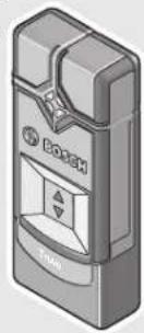
The numbering of the product features shown refers to the illustration of the measuring tool on the graphic page.
1 Marking aid
2 Signal LED
3 On/Off switch
4 Latch of battery lid
5 Battery lid
6 Serial number
7 Sensor area
Bosch Power Tools 1 609 92A 3FC(4.8.16)


18|English
Technical Data
| Digital Detector Truvo | |
| Article number | 3 603 F68 2.. |
| Maximum scanning depth*: - Ferrous metals | 70 mm |
| - Non-ferrous metals (copper pipe) | 60 mm |
| - Copper conductors (live)** | 50 mm |
| Calibration | automatic |
| Automatic switch-off after approx. | 10 min |
| Operating temperature | 0 °C . . . + 4 0 °C |
| Storage temperature | -20 °C...+70 °C |
| Relative humidity | 30 ... 80 % |
| Batteries | 3 x 1.5 V LR3 (AAA) |
| Operating lifetime (alkali-manganese batteries) approx. | 5 h |
| Weight according to EPTA-Procedure 01:2014 | 0.15 kg |
| * depending on material and size of the objects as well as material and condition of the base material (walls, ceilings, floors) ** less scanning depth for wires/conductors that are not “live” | |
| In terms of accuracy and scanning depth, the measurement result can be infe- rior in case of unfavourable surface quality of the base material. The measuring tool can be clearly identified with the serial number 6 on the type plate. | |
Assembly
Inserting/Replacing the Batteries
Alkali-manganese batteries are recommended for the operation of the measuring tool.
To open the battery lid 5, press on the latch 4 and fold the battery lid up. Insert the batteries. When inserting, pay attention to the correct polarity according to the representation on the inside of the battery compartment.
- Remove the batteries from the measuring tool when not using it for extended periods. When storing for extended periods, the batteries can corrode and self-discharge.

English | 19
Operation
Initial Operation
Protect the measuring tool against moisture and direct sun light.
Do not subject the measuring tool to extreme temperatures or variations in temperature. As an example, do not leave it in vehicles for a long time. In case of large variations in temperature, allow the measuring tool to adjust to the ambient temperature before putting it into operation. In case of extreme temperatures or variations in temperature, the accuracy of the measuring tool can be impaired.
Avoid heavy impact to or falling down of the measuring tool.
Switching On and Off
Before switching the measuring tool on, make sure that the sensor area 7 is not moist. If required, dry the measuring tool using a soft cloth.
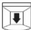
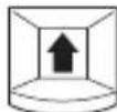
To switch on the measuring tool, slide the On/Off switch 3 downwards.
After a short self-test, the tool is ready for use. The readiness of use is indicated when the signal LED 2 illuminates. If the signal LED 2 fails to illuminate after switching on the tool, you must replace the batteries.
To switch off the measuring tool, slide the On/Off switch 3 upwards.
When no measurements are carried out for approx. 10 minutes, the measuring tool switches off automatically in order to extend the service life of the batteries.
Note: The on/off switch 3 will remain in the "on" position when the measuring tool switches itself off automatically. To switch the measuring tool back on, switch it off first before switching it on again.


20 | English
Operating Modes
The measuring tool detects objects below the sensor area 7.
Signal LED Explanation
green no object detected
yellow - metal object in the vicinity of the sensor
- small or low-lying metal object within the sensor area or
- impairment of the sensor due to unfavourable wall material
red and continuous tone metal object detected in the sensor area
red flashing (fast) and "live" wire/conductor detected intermittent sound
Detecting Metal Objects
After switching on, the signal LED 2 lights up green.
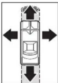
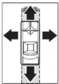
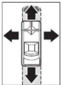
Position the measuring tool on/against the surface being detected and move it sideways.
- If no metal object is visible in the base material, then the signal LED 2 continues to illuminate green and no signal tone sounds.
- When the measuring tool comes closer to a metal object, the signal LED 2 first lights up yellow and changes to red the closer it comes to the metal object. As soon as the signal LED lights up red, a signal tone is also emitted, the pitch of which rises the closer it comes to the metal object.
- Over a metal object, the signal LED 2 illuminates red and a signal tone is emitted at maximum pitch.
Even with a yellow signal LED 2, a metal object may be located below the sensor area. Small or low-lying metal objects are located in the vicinity of the sensor or the wall material impairs the measurement results.


English | 21
After moving over the surface the first time, the position of the metal object is only roughly indicated. If you move the measuring tool over the metal object several times, the object detection will become increasingly precise. After moving over the metal object several times (without lifting the measuring tool from the base material), its position can be indicated very accurately: if the signal LED 2 illuminates red and the signal
tone sounds, the metal object is below the sensor area. When the pitch of the signal tone is highest, the metal object is located below the centre of the sensor.
Scanning for "Live" Wires
The measuring tool indicates wires, which carry voltage between 110V and 240V and a frequency corresponding to the widely used standard (AC with 50 or 60Hz ). Other wires (carrying DC, higher/ lower frequency or voltage) as well as non-"live" wires/conductors cannot be found reliably, but are possibly indicated as metal objects.
The detection for "live" wires/conductors takes place automatically with every measurement. When a "live" wire/conductor is detected, the signal LED 2 flashes red and an intermittent signal tone sounds with rapid tone sequence. Move the measuring tool repeatedly over the surface to locate the "live" wire/conductor more precisely. After moving over the surface several times, the position of the "live" wire/conductor can be indicated very accurately.
It is easier to find live cables if electricity consumers (e.g. lights, appliances) are connected to the cable being searched for and are switched on. Switch off electricity consumers before drilling, sawing or milling into the wall.
Note: Always ensure that you hold the measuring tool firmly without gloves to enable a good grounding. Also ensure that ladders/scaffolding must be grounded. Avoid ladders/scaffolding whose supports have plastic caps underneath them. Do not wear insulating footwear.
It may not be possible to find live cables in certain conditions (e.g. behind metal surfaces, behind surfaces that are very dry or very damp). If the indicator LED 2 lights up yellow or red over a large area, the material is electrically shielded and you will not be able to find live cables accurately.


22 | English
Working Advice
To avoid affecting the measurement, do not hold the measuring tool within range of the sensor. This will enable you to obtain more accurate measurement results.
Marking Objects
Detected objects can be marked as required. The outer edges of an object are indicated by the colour change of the signal LED 2 from yellow to red. The centre of the metal object can be determined by the pitch. Using a pen, mark the sought after location at the top and the side marker aids 1.
Continuous Flashing Green/Yellow/Red
If the signal LED 2 flashes alternately green, yellow and red, even when no metal object or no "live" cable is in the vicinity, the measuring device must be sent in for service.
Maintenance and Service
Manual Calibration
If the signal LED 2 illuminates red or yellow, even when no metal is in the vicinity of the measuring tool, the tool must be recalibrated.
- To do this, switch the measuring device on using the On/Off switch 3.
- Remove a battery from the switched on measuring device.
- While the battery is removed, switch the measuring device off using the On/Off switch 3.
- Reinsert the batteries into the measuring device (pay attention to the polarity!).
- Now remove all objects in the vicinity of the measuring device (including wrist watches or rings of metal) and hold the measuring tool up in the air.
- Switch the measuring device on using the On/Off switch 3 and off again within 3 seconds. The signal LED 2 of the measuring device will flash red in slow succession during the 3 seconds to indicate that it is ready to calibrate.
- Switch the measuring device back on within 0.5 seconds. The calibration is initiated and takes about 6 seconds. The signal LED 2 will flash green for 6 seconds in quick succession, the calibration is being performed. Now the device is once more ready for operation and the signal LED 2 illuminates solid green.

English | 23
Note: If the sequence of switching off then on again is not followed, no calibration is performed. The signal LED 2 remains either yellow or red, even though no metal is located within the vicinity. In this case, repeat the calibration.
Troubleshooting - Causes and Corrective Measures
Cause Corrective Measure
Signal LED 2 does not illuminate.
| Measuring tool is not switched on | Switch the measuring tool on. |
| Measuring tool has switched itself off | Switch the measuring tool off and then on again. |
| Batteries have not been inserted or been inserted incorrectly | Insert batteries. Pay attention to the polarity. |
| Flat or rechargeable batteries inserted | Replace batteries. Do not use rechargeable batteries. |
| Signal LED 2 illuminates yellow or red, even though no metal is located within the vicinity (warning of metal objects). | |
| Ambient temperature is too high/too low | Only use the measuring tool within the specific temperature range of 0 °C–40 °C. |
| Severe temperature change | Wait until the measuring tool acclimates to the ambient temperature. |
| Auto calibration not successful | Perform a manual calibration. |
| * Therefore, please also observe other information sources (e.g. construction plans) before drilling, sawing or routing into walls, ceilings or floors. | |
24|English
Cause Corrective Measure
Signal LED 2 lights yellow or red over large measuring area on the wall (warning of metal objects).
| Many, closely spaced metal objects | Pay attention to the pitch of the signal sound to differentiate between individual metal objects. Metal objects that are too closely spaced, cannot be detected separately.* |
| Building materials containing metal or reinforcing steel in the concrete | A reliable detection is not possible with metallic building materials (e.g. foil-laminated insulation materials, heat sinks).* |
| Solid metal objects on the back of the wall | Detection will not be accurate in the presence of solid metal objects (e.g. radiators).* |
| Auto calibration not successful | Perform a manual calibration. |
| Signal LED 2 flashes red over a large measuring area on the wall (warning of “live” cables). | |
| Improper grounding of the wall | With your free hand, touch the wall at a distance of 20-30 cm from the measuring tool to ground the wall. |
| * Therefore, please also observe other information sources (e.g. construction plans) before drilling, sawing or routing into walls, ceilings or floors. | |

English | 25
Cause Corrective Measure
"Live" cable is not found.
| No/atypical voltage on the cable | Add voltage to the cable, for example by turning on light switches assigned to it. The detection of cables with AC voltages outside of the range 110-240 V, 50-60 Hz is not reliably possible.* |
| Cable is located too deep. | The scanning depth is dependent on the building material and may be less than the maximum scanning depth.* |
| Cable runs in grounded metal pipe. | Use the measuring tool to locate the metal pipe. |
| Measuring tool is not grounded. | Hold the measuring tool firmly without gloves. Do not stand on insulating ladders or scaffolding. Do not wear insulating footwear. |
| Shielding building material or humidity too low/too high | Detection will not be accurate in the presence of metallic building materials or building materials that are too dry or too damp (e.g. if the humidity is too low or too high).* |
| Metal object is not located. | |
| Metal object is located too deep. | The scanning depth is dependent on the building material and may be less than the maximum scanning depth.* |
| Metal object is too small. | The scanning depth is dependent on the building material and may be less than the maximum scanning depth.* |
| Uncoordinated flashing in colours green, yellow, red | |
| Interference caused by electric or magnetic fields | Keep your distance from devices emitting strong electric or magnetic fields (e.g. computers, switch mode power supplies). |
| *Therefore, please also observe other information sources (e.g. construction plans) before drilling, sawing or routing into walls, ceilings or floors. | |


26 | English
Cause Corrective Measure
Measurement results inaccurate/implausible
| Interfering metal objects in the area of the sensor | Remove all interfering metal objects (e.g. watches, bracelets, rings, etc.) from within range of the sensor. Do not hold the measuring tool close to the sensor. |
Auto calibration not Perform a manual calibration. successful
Continuous flashing green/yellow/red, even when no metal or "live" cable is in the vicinity.
Measuring tool is Send the measuring tool in for service. defective.
- Therefore, please also observe other information sources (e.g. construction plans) before drilling, sawing or routing into walls, ceilings or floors.
Maintenance and Cleaning
Wipe away debris or contamination with a dry, soft cloth. Do not use cleaning agents or solvents.
In order not to affect the measuring function, decals/stickers or name plates, especially metal ones, may not be attached in the sensor area 7 on the front or back side of the measuring tool.
After-sales Service and Application Service
Our after-sales service responds to your questions concerning maintenance and repair of your product as well as spare parts. Exploded views and information on spare parts can also be found under:
www.bosch-pt.com
Bosch's application service team will gladly answer questions concerning our products and their accessories.
In all correspondence and spare parts orders, please always include the 10-digit article number given on the nameplate of the product.


English | 27
Great Britain
Robert Bosch Ltd. (B.S.C.)
P.O.Box 98
Broadwater Park
North Orbital Road
Denham
Uxbridge
UB95HJ
At www.bosch-pt.co.uk you can order spare parts or arrange the
collection of a product in need of servicing or repair.
Tel. Service: (0344) 7360109
E-Mail: boschservicecentre@bosch.com
Ireland
Origo Ltd.
Unit 23 Magna Drive
Magna Business Park
City West
Dublin 24
Tel. Service: (01) 4666700
Fax: (01) 4666888
Australia, New Zealand and Pacific Islands
Robert Bosch Australia Pty. Ltd.
Power Tools
Locked Bag 66
Clayton South VIC 3169
Customer Contact Center
Inside Australia:
Phone: (01300) 307044
Fax: (01300) 307045
Inside New Zealand:
Phone: (0800) 543353
Fax: (0800) 428570
Outside AU and NZ:
Phone: +61 395415555
www.bosch.com.au

28|English
Republic of South Africa
Customer service
Hotline: (011) 6519600
Gauteng - BSC Service Centre
35 Roper Street, New Centre
Johannesburg
Tel.: (011) 4939375
Fax: (011) 4930126
E-Mail: bsctools@icon.co.za
KZN - BSC Service Centre
Unit E, Almar Centre
143 Crompton Street
Pinetown
Tel.: (031) 7012120
Fax: (031) 7012446
E-Mail: bsc.dur@za.bosch.com
Western Cape - BSC Service Centre
Democracy Way, Prosperity Park
Milnerton
Tel.: (021) 5512577
Fax: (021) 5513223
E-Mail: bsc@zsd.co.za
Bosch Headquarters
Midrand, Gauteng
Tel.: (011) 6519600
Fax: (011) 6519880
E-Mail: rbsa-hq.pts@za.bosch.com
Disposal
Measuring tools, accessories and packaging should be sorted for environmental-friendly recycling.
Do not dispose of measuring tools and batteries/rechargeable batteries into household waste!
Francais|29
Only for EC countries:

According to the European Guideline 2012/19/EU, measuring tools that are no longer usable, and according to the European Guideline 2006/66/EC, defective or used battery packs/batteries, must be collected separately and disposed of in an environmentally correct manner.
Batteries no longer suitable for use can be directly returned at:
Great Britain
Robert Bosch Ltd. (B.S.C.)
P.O.Box 98
Broadwater Park
North Orbital Road
Denham
Uxbridge
UB95HJ
At www.bosch-pt.co.uk you can order spare parts or arrange the collection of a product in need of servicing or repair.
Tel. Service: (0344) 7360109
E-Mail: boschservicecentre@bosch.com
Subject to change without notice.
Français
Robert Bosch (France) S.A.S.
Bosch Service Center
Telegrafvej 3
2750 Ballerup
Pá www.bosch-pt.dk kan der online bestilles reservedele eller oprettes en
reparations ordre.
TIf. Service Center: 44898855
Fax:44898755
E-Mail: vaerktoej@dk.bosch.com
Bortskaffelse
Bosch Service Center
Telegrafvej 3
2750 Ballerup
Danmark
Tel.: (08) 7501820 (inom Sverige)
Fax: (011) 187691
1609 92A 3FC | (4.8.16) Bosch Power Tools


Norsk|111
Avfallschantering
Endast for EU-lander:
Mny pIeTe Ta epyaaleia metponc kal tic mataplic ota anoppmuata tou ontiou oac!
Movi yia xwpec tnc EE:

2 0jwJg Jy jy Jn no wJll ooc JI J I J I J I J I J I J I J I J I J I J I J I J I J I J I J I J I J I J I J I J I J I J I J I J I J I J I J I J I J I J
Jd2all
jagg jagl 2 oJw g a Jaaal paaa I gg
oojgoojw
2 2 2 2 2 2 2 2 2 2 2 2 2 2 2 2 2 2 2 2 2 2 2 2 2 2 2 2 2 2 2 2 2 2 2 2 2 2 2 2 2 2 2 2 2 2 2 2 2 2
UJIJI 1

psggo yjwai jyjwajugdic
oocjosig. jyjowbqj
sjjj jdyallpwll gog ooc wlaal
oocjowg.wwjwl (jswll gogo cgcwll oocg) o: jdwllpwll gogo l qdoyjw2 jds 2 jw2 jw2 jw2 jw2 jw2 jw2 jw2 jw2 jw2 jw2 jw2 jw2 jw2 jw2 jw2 jw2 jw2 jw2 jw2 jw2 jw2 jw2 jw2 jw2 jw2 jw2 jw2 jw2 jw2 jw2 jw2 jw2 jw2 jw
wJ

jLgS Lg yIy I gblnJc
jg jy yj yj yj yj yj yj yj yj yj yj yj yj yj yj yj yj yj yj yj yj yj yj yj yj yj yj yj yj yj yj yj yj yj yj yj yj yj yj yj yj yj yj yj yj yj yj yj yj yj yj y
jU|I) 5gA aJI gJ U b gB J I lo. (jJ60 g1 50 a a
Igblgbll lSg (J/1c21 s jll gJ qjaiuai
ducu 1Jsw qucu cquil ay 2 a yjus y jy
aJxoo pIwI IeI Uc IeI JUwU Ou xSjSg
suc yjusy jy bgsbJc uLklogg p 1000000000000000000000000000000000000000000000000000000000000000
1609 92A 3FC | (4.8.16) Bosch Power Tools


167
g 100000000000000000000000000000000000000000000
.1j8IgLqbgaw gJwJll oJyOyDshll Cooa
LbIg Juswll
7 wlll 1 y wll l s s s s s
/山 13
g. 2 oJwI g oJwI I JI JI JI JI JI JI JI JI JI JI JI JI JI JI JI JI JI JI JI JI JI JI JI JI JI JI JI JI JI JI JI JI JI JI JI JI JI JI JI JI JI JI JI JI
/1sui 3
aLac 1 aJ u J aJ bUJI aJ UJ aJ UJ UJ UJ UJ UJ
a liao u bssu, u log g i wuall osc g l o j 1j: abdo
wluai ooc u wu olc. u wu 3 o/ u wu
. quwu x p j xg l qagg

山
| اللهُّل | اللهُّل | |
| ojlalil klsj ybjr jz jz jz jz jz jz jz jz jz jz jz jz jz jz jz jz jz jz jz jz jz jz jz jz jz jz jz jz jz jz jz jz jz jz jz jz jz jz jz jz jz jz jz jz jz jz jz jz jz jz jZj. | 2 | |
| jw sh w jw sh w jw sh w jw sh w jw sh w jw sh w jw sh w jw sh w jw sh w jw sh w jw sh w jw sh w jw sh w jw sh w jw sh w jw sh w jw sh w jw sh w jw sh w jw sh w jw sh w jw sh w jw sh w jw sh w jw sh w jw sh wj. | d j z j d j l j d j d j d j d j d j d j d j d j d j d j d j d j d j d j d j d j d j d j d j d j d j d j d j d j d j d j d j d j d j d j d j d j d j d j d j d j d j d j d j d j d j d j d j d j d j d j d j d j d j d jd j d j d j d j d j d j d j d j d j d j d j d j d j d j d j d j d j d j d j d j d j d j d j d j d j d j d j d j d j d j d j d j d j d j d j d j d j d j d j d j d j d j d j d j d j d j d j d j d j d j D J D J D J D J D J D J D J D J D J D J D J D J D J D J D J D J D J D J D J D J D J D J D J D J D J D J D J D J D J D J D J D J D J D J D J D J D J D J D J D J D J D J D J D J D J D J D J D J D J D J DJ D J D J D J D J D J D J D J D J D J D J D J D J D J D J D J D J D J D J D J D J D J D J D J D J D J D J D J D J D J D J D J D J D J D J D J D J D J D J D J D J D J D J D J D J D J D J D J D J D J D j. | |
| g i jla) j l j l j l j l j l j l j l j l j l j l j l j l j l j l j l j l j l j l j l j l j l j l j l j l j l j l j l j l j l j l j l j l j l j l j l j l j l j l j l j l j l j l j l j l j l j l j l j l j l j l j I J I J I J I J I J I J I J I J I J I J I J I J I J I J I J I J I J I J I J I J I J I J I J I J I J I J I J I J I J I J I J I J I J I J I J I J I J I J I J I J I J I J I J I J I J I J I J I J I J I J I I J I J I J I J I J I J I J I J I J I J I J I J I J I J I J I J I J I J I J I J I J I J I J I J I J I J I J I J I J I J I J I J I J I J I J I J I J I J I J I J I J I J I J I J I J I J I J I J I J IJ I J I J I J I J I J I J I J I J I J I J I J I J I J I J I J I J I J I J I J I J I J I J I J I J I J I J I J I J I J I J I J I J I J I J I J I J I J I J I J I J I J I J I J I J I J I J I J I J I J I | ||
| g i jla) j l j l j l j l j l j l j l j l j l j l j l j l j l j l j l j l j l j l j l j l j l j l j l j l j l j l j l j l j l j l j l j l j l j l j l j l j l j l j l j l j l j l j l j l j l l l l l l l l l l l l l l l l l l l l l l l l l l l l l l l l l l l l l l l l l l l l l l l l l l l l l l l l l l l l l l l l l l l l l l l l l l l l l l l l l l l l l l l l l l l l l l l l l l l l L J I J I J I J I J I J I J I J I J I J I J I J I J I J I J I J I J I J I J I J I J I J I J I J I J I J I J I J I J I J I J I J I J I J I J I J I J I J I J I J I J I J I J I J I J I J I J I J I J I JI J I J I J I J I J I J I J I J I J I J I J I J I J I J I J I J I J I J I J I J I J I J I J I J I J I J I J I J I J I J I J I J I J I J I J I J I J I J I J I J I J I J I J I J I J I J I J I J I J I J J I J I J I J I J I J I J I J I J I J I J I J I J I J I J I J I J I J I J I J I J I J I J I J I J I J I J I J I J I J I J I J I J I J I J I J I J I J I J I J I J I J I J I J I J I J I J I J I J I J! | ||
| g i jla) j l j l j l j l j l j l j l j l j l j l j l j l j l j l j l j l j l j l j l j l j l j l j l j l j l j l j l j l j l j l j l j l j l j l j l j l j l j l j l j l j l j l j l j l j l f j. | ||
| g i jla) j l j l j l j l j l j l j l j l j l j l j l j l j l j l j l j l j l j l j l j l j l j l j l j l j l j l j l j l j l j l j l j l j l j l j l j l j l j l j l j l j l j l j l j l l l l l l l l l l l l L J I J I J I J I J I J I J I J I J I J I J I J I J I J I J I J I J I J I J I J I J I J I J I J I J I J I J I J I J I J I J I J I J I J I J I J I J I J I J I J I J I J I J IJ! | ||
| g i jla) j l j l j l j l j l j l j l j l j l j l j l j l j l j l j l j l j l j l j l j l j l j l j l j l j l j l j l j l j l j l j l j l j l j l j l j l j l j l j l j l j l j l j l j l j I J I J I J I J I JI J I J I J I J I J I J I J I J I J I J I J I J I J I J I J I J I J I J I J I J I J I J I J I J I J I J I J I J I J I J I J I J I J I J I J I J I J I J I J I J I J I J I J I J IJ! | ||
| g i jla) j l l l l l l l l l l l l l l l l l l l l l l l l l l l l l l l l l l l l l l l l l l l l l l l l l l l l l l l l l l l l l l l l l l l l l l l l l l l l l l l l l l l l l l l l l l l l l l l l l l LJ! | ||
| g i jla) j l l l l l l l l l l l l l l l l l l l l l l l l l l l l l l l l l l l l l l l l l l l l l l l l l l l l l l l l l l l l l l l l l l l l l l l l l l l l l l l l l l l l l l l LJ! | ||
| g i jla) i j i i i i i i i i i i i i i i i i i i i i i i i i i i i i i i i i i i i i i i i i i i i i i i i i i i i i i i i i i i i i i i i i i i i i i i i i i i i i i i i i i i i i i i i i i i i i i i i i i i i i 10000000000000000000000000000000000000000000000000000000000000000000000000000000000000000000000000000 | ||
| g i jla) i j i i i i i i i i i i i i i i i i i i i i i i i i i i i i i i i i i i i i i i i i i i i i i i i i i i i i i i i i i i i i i i i i i i i i i i i i i i i i i i i i i i i i i i i i i 100000000100000000000000000000000000000000000000000000000000000000000000000000000000000000000000000000000000 |
Bosch Power Tools 1609 92A 3FC| (4.8.16)

174|L
g w j 2 u 1 g 1 g 1 g 1 g 1 g 1 g 1 g
Jolgulc-1ba
| . . . . . . . . . . . . . . . . . . . . . . . . . . . . . . . . . . . . . . . . . . . . . . . . . . . . . . . . . . . . . . . . . . . . . . . . . . . . . . . . . . . . . . . . . . . . . . . . . . . . .. . . . . . . . . . . . . . . . . . . . . . . . . . . . . . . . . . . . . . . . . . . . . . . . . . . . . . . . . . . . . . . . . . . . . . . . . . . . . . . . . . . . . . . . . . . . . . . . . . . . . . . . . . . . . . . . . . . . . . . . . . . . . . . . . . . . . . . . . . . . . . . . . . . . . . . . . . . . . . . . . . . . . . . . . . . . . . . . . . . . . . . . . . . . . . . . . . . . . . . .. . . . . . . . . . . . . . . . . . . . . . . . . . . . . . . . . . . . . . . . . . . . . . . . . . . . . . . . . . . . . . . . . . . . . . . . . . . . . . . . . . . . . . . . . . . . . . . . . . . .. . . . . . . . . . . . . . . . . . . . . . . . . . . . . . . . . . . . . . . . . . . . . . . . . . . . . . . . . . . . . . . . . . .. . . . . . . . . . . . . . . . . . . . . . . . . . . . . . . . . . . . . . . . . . . . . . . . . . . . . . . . . . . . . . . . . . . . . . . . . . . . . . . . . . . . . . . . . . . . . . . . . . . . ? . . . . . . . . . . . . . . . . . . . . . . . . . . . . . . . . . . . . . . . . . . . . . . . . . . . . . . . . . . . . . . . . . . . . . . . . . . . . . . . . . . . . . . . . . . . . . . . . . . . 2 2 2 2 2 2 2 2 2 2 2 2 2 2 2 2 2 2 2 2 2 2 2 2 2 2 2 2 2 2 2 2 2 2 2 2 2 2 2 2 2 2 2 2 2 2 2 2 2 2 2 |
1609 92A 3FC | (4.8.16) Bosch Power Tools
Joc sllaia
SjS oJl j Sj SsO sSoo gdo J 1 SjS oJl jI J I .G CwS D GJJ GgS oJl jL iui agSj. gwi Jaa
Lull
. 2 JliSswgJwJgJgJgJgJgJgJgJgJgJgJgJgJgJgJgJgJgJgJgJgJgJgJgJgJgJgJgJgJgJgJgJgJgJgJgJgJgJgJgJgJgJgJgJgJgJgJgJgJgJgJ
j0j/3jj/jw soo jSj Saa
2 2j j 1j j j j j j j j j j j j j j j j j j j j j j j j j j j j j j j j j j j j j j j j j j j j j j j j j j j j j j j
uugw9 1j0
LwS pbi
a dS s g g b, g w w j j oj 2 uLk w g Jd j 20j l j 1j 3u oJl j 1j 1j 1j 1j 1j 1j 1j 1j 1j 1j 1j 1j 1j 1j 1j 1j 1j 1j 1j 1j 1j 1j 1j 1j 1j 1j 1j 1j 1j 1j 1j 1j 1j 1j

Bosch Power Tools 1609 92A 3FC| (4.8.16)
176|LwJl
g j 1j j j j j j j j j j j j j j j j j j j j j j j j j j j j j j j j j j j j j j j j j j j j j j j j j j j j j j j j j j j j j j j j j j j j j j j j j j j j j j j j j j j j j j j j
Jololola 1sIgss
240Vg110V jIgJgLdS gSg (60Hz 50 yglg)Ugao Jy dJy g
y/2yjg) LgLg.
yjg.
yjg.
yjg.
yjg.
yjg.
yjg.
yjg.
yjg.
yjg.
yjg.
yjg.
yjg.
yjg.
yjg.
yjg.
yjg.
yjg.
yjg.
yjg.
yjg.
y
J 1 J 1 J 1 J 1 J 1 J 1 J 1 J 1 J 1 J 1 J 1 J 1 J 1 J 1 J 1 J 1 J 1 J 1 J 1 J 1 J 1 J 1 J 1 J 1 J 1 J 1 J 1 J 1 J 1 J 1 J 1 J 1 J 1 J 1 J
1609 92A 3FC | (4.8.16) Bosch Power Tools

Lslac gil
.5s 7 jSsa oSg oo JJ |j |u| j|j|j|
aogj gjjio- jlllJ jI oJoaJwJyS OJsl JjI JSL
JgW
40s5 5 jduo
.1515115151515151515151515151515151515151515151515151515151515151515
gub yjul slo uo aunu nn l jg au yjul yjlspl
J. J. J. J. J. J. J. J. J. J. J. J. J. J. J. J. J. J. J. J. J. J. J. J. J. J. J. J. J. J. J. J. J. J. J. J. J. J. J. J. J. J. J. J. J. J. J. J. J. J. J.
a aai 1jI bawg I aia oJls JjI jI aai
i jn i .sblol lalb qI oiaow cba g

Jl j 1 Jg b oJ l j 1 g 1 g 1 g 1 g 1 g 1 g 1 g 1 g 1 g 1 g 1 g 1 g 1 g 1 g 1 g 1 g 1 g 1 g 1 g 1 g 1 g 1 g 1 g 1 g 1 g 1 g 1 g 1 g 1 g 1 g 1 g 1 g 1 g 1 g

J 1 J 1 J 1 J 1 J 1 J 1 J 1 J 1 J 1 J 1 J 1 J 1 J 1 J 1 J 1 J 1 J 1 J 1 J 1 J 1 J 1 J 1 J 1 J 1 J 1 J 1 J 1 J 1 J 1 J 1 J 1 J 1 J 1 J 1 J


1
C
| de EU-Konformitäts-erklärung Digitales Ortungs-gerät | Sachnummer | Wir erklären in alleiniger Verantwortung, dass die genannten Produkte allen ein-schlädiggen Bestimmungen der nachfol-gend aufgeführten Richtlinien und Verord-nungen entsprechen und mit folgenden Normen übereinstimmen. Technische Unterlagen bei: * |
| en EU Declaration of Conformity Digital Detector | Article number | We declare under our sole responsibility that the stated products comply with all applicable provisions of the directives and regulations listed below and are in con-formity with the following standards. Technical file at: * |
| fr Déclaration de conformité UE Décteur numérique | N° d'article | Nous déclarons sous notre propre responsabilité que les produits décrits sont en conformité avec les directives, règles normatifs et normes écuminés ci-dessous. Dossier technique auprès de: * |
| es Declaración de conformidad UE Detector Digital | No de articulo | Declaramos bajo notre exclusive responsabilité, que los produits nombrados cumplen con todas las disponeciones cor-respondientes de las Directivas y los Regla-mentos Mentionados a continuación y están en conformidad con las siguientes normas. Documentos技术和 de: * |
| pt Declaração de Conformidade CE Detetor digital | N.° doProduto | Declaramos sob{nossa exclusiva responsa-bilidaque os produits Mentionados cumprem todas as disponções e os regula-mentos indicados e está em conformi-dade com as seguides normas. Documentação和技术a pertencente à: * |


#
II
| it Dichiarazione di conformità UE | Dichiariamo molto la nostra piena respon-sabilità che i prodotti indicate sono con-formi a tutte le disposizioni pertinenti delle Direttive e dei Regolamenti elencati di seguito, nonché alle seguenti Normative. Documentazione Tecnica presso: * | |
| Località-tore digi-tale | Codice prodotto | |
| nl EU-conformiteits-verklaring | Wij verklaren op eigenverantwoordelijk-heid dat de genoemde producten voldoen aan alle desbetreffende bepalingen van de hierna genoemde richtlijnen en verorde-ningen en overeenstemmen met de vol-gende normen. Technisch dossier bij: * | |
| Digitale detector | Product-number | |
| da EU-overensstemmelses-erklæring | Vi erklærer som eneansvarlige, at det beskreve produit er i overensstemmelse med alle geldende bestemmelse i føl-gende direktiver og forordninger og opfyl-der følgende standarder. Tekniske bilag ved: * | |
| Digitalt Pejle-værktøj | Typenummer | |
| sv EU-konformitets-förklaring | Vi förklarar under eget ansvar att de nämnda produkterna uppfyller kraven i alla gällande bestämmelser i de nedan angivna direktiven och Förordningarnas och att de stämmer överens med följande normer. Teknisk dokumentation: * | |
| Digitaldetektor | Produkt-number | |
| no EU-samsvarserklaering | Vi erklærer unter eneansvar at de nevnte Produktene er i overensstemmelse med alle relevante bestemmelse i direktivene og forordningene nedenfor og med føl-gende standarder. Teknisk dokumentasjon hos: * | |
| Digitaldetektor | Produkt-number | |

III
C
Executive Vice President
Engineering and
Manufacturing

Helmut Heinzelmann
Head of Product Certification

Robert Bosch Power Tools GmbH, 70538 Stuttgart, GERMANY
Stuttgart, 01.01.2017