FET - Saw PROXXON - Free user manual and instructions
Find the device manual for free FET PROXXON in PDF.
| Product Type | Precision circular saw |
| Brand | Proxxon |
| Model | FET |
| Dimensions (L x D x H) | 300 x 320 x 170 mm (with blade guard approx. 220 mm) |
| Power supply | 220-240 V, 50/60 Hz |
| Power consumption | 200 W (KB 10 min) |
| No-load speed | 7000 rpm |
| Max. blade diameter | 85 mm |
| Max. sawing depth | 25 mm |
| Blade bore | 10 mm |
| Riving knife thickness | 1.2 mm |
| Sound pressure level (LPA) | 89.7 dB(A) |
| Sound power level (LWA) | 102.7 dB(A) |
| Vibrations | < 2.5 m/s² |
| Main functions | Height and tilt adjustment of blade, rip fence with precision scale, miter fence, extension table, dust extraction, automatic blade guard |
| Maintenance and cleaning | External cleaning with soft cloth, internal cleaning with vacuum after lifting the cover; belt and blade replacement described in the manual |
| Safety | Automatic blade guard, motor stop when lifting the cover, mandatory use of push stick for small pieces, mandatory connection of vacuum cleaner |
| Spare parts and repairability | Proxxon saw blades (ref. 28 731, 28 732, 28 734, 28 735); repairs by Proxxon central service |
| General information | Indoor use, do not dispose of with household waste; CE declaration according to applicable directives |
Frequently Asked Questions - FET PROXXON
User questions about FET PROXXON
0 question about this device. Answer the ones you know or ask your own.
Ask a new question about this device
Download the instructions for your Saw in PDF format for free! Find your manual FET - PROXXON and take your electronic device back in hand. On this page are published all the documents necessary for the use of your device. FET by PROXXON.
USER MANUAL FET PROXXON
Fold out the picture pages when reading the user instructions.

23-30
Français
- In general 15
- Specific safety regulations for circular saw benches 15
3.Description of machine 16 - Legend (fig. 1) 16
- Technical data 16
- Setting up the saw 16
6.1.Unpacking 16
6.2. Swinging open the upper housing part 17
6.3. Fastening the saw 17
6.4. Saw blade guard 17
6.4.1. Secure the saw blade guard with the splitting wedge 17 - Settings 17
7.1.Height adjustment of the saw blade 17
7.2. Adjusting the saw blade tilt 18 - Extendable saw table 18
9.Dust suction 18 - Working with the limit stops 18
10.1. Working with the longitudinal stop 18
10.1.1. Inserting, or removing, the longitudinal stop 18
10.1.2. Rough adjustment of the longitudinal stop 18
10.1.3. Adjusting the longitudinal stop with the help of the scale 18
10.1.3.1. Adjusting the limit stop scale (zero position) 19
10.1.4. Fine adjustment of the longitudinal stop 19
10.2. Auxiliary stop 19
10.3. Angle stop 19
10.4. Working with the limit stop strip with clamping piece for angle stop 19
10.4.1. Assembly and adjustment 19 - Sawing 19
11.1. General tips on sawing 20 - Changing the saw blade 20
12.1. Choosing the right saw blade 20 - Maintenance and repairs: 21
13.1. Cleaning the housing 21
13.2. Cleaning the inside of the device 21
13.3. Replacing the toothed belt 21 - Disposal 22
- CE Declaration 22
1. In general
Dear Customer!
The use of these instructions
- makes it easier to become acquainted with the device,
- prevents malfunctions due to improper handling, and
increases the service life of your device.
Always keep these instructions close to hand.
Only operate this device with exact knowledge of it and comply with the instructions.
PROXXON will not be liable for the safe function of the device for:
- handling that does not comply with the usual intended use,
- other application uses that are not stated in the instructions,
- disregard of the safety regulations.
You will not have any warranty claims for:
operating errors,
- lack of maintenance.
For your safety, please comply with the safety regulations at all costs.
Only use original PROXXON spare parts.
All rights reserved for further developments within the meaning of technical progress. We wish you much success with the device.
2. Specific safety regulations for circular saw benches
- Do not use deformed or flawed saw blades.
- Replace worn bench inserts.
- Use only the saw blades recommended by Proxxon. Utilised saw blades must comply with EN 847-1. The saw-cut may not be smaller than the thickness of the splitting wedge.
- Make sure the saw blade is suitable for the material to be sawn.
- Wear hearing protection!
- The sawdust from certain materials can be hazardous to your health. Therefore, wear a respirator.
- Wear gloves when handling saw blades and rough materials!
- Only operate the saw with a dust suction device! Your saw has a connecting piece at the back for this purpose. You can connect a vacuum cleaner here.
- For smaller work pieces, use a push-rod for the feed!
- Never work with a device that has faulty or defective parts. Your circular saw might no longer be safe. Therefore, have any damage immediately repaired by the Proxxon Customer Service!

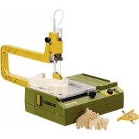
3. Description of machine
The FET table saw is a well thought-out machine for all occurring sawing tasks in the range of small and fine applications.
A powerful motor, solid mechanics, high-quality materials and meticulous production make this a reliable tool for all possible sawing applications.
Depending on the utilised saw blades, all types of wood, many non-ferrous metals, ceramics and plastics as well as many other materials can be processed with the machine.
The corresponding saw blades can be obtained from Proxxon and will be mentioned in more detail later on.
The bench is made of stable aluminium die casting and forms one unit together with the motor suspension: The guarantees the highest strength and naturally also affects the precision of the working results.
To guarantee the highest possible flexibility, we offer different types of limit stops that are included with the machine. So there is something for every application:
There is a longitudinal stop that runs in a guide along the front of the bench that can be easily shifted and arrested by hand, or which can be used with the precisely adjustable graduated scale.
Adjusting capabilities in the tenth of a millimetre range leave nothing to be desired and make it easy to saw work pieces to the desired, previously adjusted measure.
In addition there is a sophisticated and precise angle stop which can be extended with an aluminium profile strip with a moving clamping piece for the exact reproduction of many parts to be sawed out with equal angles and each with the same dimensions.
The safety aspect was taken care of as well: The saw blade is covered by a sturdy saw blade guard which automatically moves up when contact is made with the work piece, and which only releases as much of the saw blade as necessary. Caution!
For your own safety, it is understood that the saw may never be operated without this protective guard!
The upper part of the device is hinged so that it can be opened for cleaning and maintenance purposes. Thus the interior of the device can be cleaned of chips and dust with a vacuum cleaner, for example. To exclude any kind of hazard, a switching contact disconnects the electrics from the power mains when the upper housing part is open.
But during all cleaning, maintenance and adjusting work (and of course during sawing) please remember that your FSK is not a play toy but a tool for woodworking and is thus a potential source of danger!
Among others a push-rod for the secure feed of more compact work pieces and two Allen keys are also included in the delivery. These can be stored in a „key parking slot" on the right side of the housing.
In the interests of your own safety, please carefully read through and comply with the attached safety notes, which are also mentioned in these instructions, and make sure that you have also understood them!
4. Legend (fig. 1)
- Saw blade guard
- Saw table
- Saw blade
- Connection for dust suction
- Longitudinal stop
- Key parking slot
- Rubber connecting piece for suction
- Allen key
- Allen key
- Push-rod
- Angle stop
- Knurled screw for fine adjusting
- Motor unit
- Angle scale for saw blade tilt
- Saw blade adjustment for depth of cut
- Clamping piece
- Limit stop strip
- Mains cable
- On - Off switch
- Scale for longitudinal stop
- Extendable saw support
- Auxiliary stop
5. Technical data
Rotational speed: 7000/min
Saw blade diameter max. 85 mm
Depth of cut max.: 25 mm
Saw blade drill hole: 10 mm
Splitting wedge thickness 1.2 mm
Dimensions (in mm):
Width: 300 mm
Depth: 320 mm
Height: 170 mm (with saw
blade guard approx. 220 mm)
Motor:
Voltage: 220/240 Volt, 50/60 Hz
Power consumption: 200 W KB 10 min
Noise level:
LWA 102.7 dB(A)
Vibration
< 2.5 m/s
Only use in the house
Do not dispose of the device in household waste
6. Setting up the saw
6.1. Unpacking
Caution!
Please note that transport blocks have been attached to the device during packing to avoid damage during transportation. Make sure you remove all of them before commissioning! Carefully read through the instructions and especially observe the following chapter!
A transport block made of cardboard is inserted on the inside of the saw. This must be removed before initial commissioning. How to swing up the upper housing part is explained in the following chapter.
6.2. Swinging open the upper housing part
- Please open the packaging box to unpack, carefully remove the saw and deposit it on a firm and level surface.
- Release the knurled screw 1 (fig. 2) and swing up the upper housing part 2.
- Permit the latch 3 to engage.
- Before first commissioning, remove the cardboard that was used as safeguard during the transport.
- Release the latch 3 of the support and push the upper housing part back down. Caution! Hold on to the upper part when pushing down! Injuries might be caused if the upper part drops down unchecked.
- Retighten knurled screw 1.
6.3. Fastening the saw
Generally the saw must be set up on a fixed and level surface, ideally on a heavy workbench or a solid table. To obtain a secure hold, your FET should be screwed to the surface: For this purpose there are four holes in the housing bottom so that fastening screws can be screwed into them.
Note:
Safe and precise work is only possible with careful fastening! Therefore, please proceed as follows:
Caution!
Make sure the mains plug is disconnected!
- Swing up the upper part of the saw
- Permit the latch to engage
- Now you can see four hexagonal indentations on the in - side above the four screw holes in the housing bottom, see fig. 3. These are intended to receive M5 hexagon nuts, or the heads of M5 hexagon screws. Insert sufficiently long screws 2 from inside through the opening in the housing bottom and bolt them through the drill holes that you previously drilled in the underlay 3. Use a drilling template for the required hole spacing. You will find a sketch with the dimensions at fig. 4.
- Then release the latch of the support and push the upper housing part back down.
- Do not forget to tighten the knurled screw 1 (fig. 2)!
6.4. Saw blade guard
Your FET is equipped with a saw blade guard. It is designed in such a way that moves up as far as necessary during sawing and then drops back into its home position. It also adapts to the various adjusted cutting depths.
Caution!
The saw blade guard is an important safety tool and may in no way be tampered with or even dismantled. Operating the saw without this guard is dangerous!
While setting up and transporting the saw, always may sure that the upper saw blade cover is in its correct position. The free-lying, sharp teeth of the saw blade pose a considerable risk of injury!
6.4.1. Secure the saw blade guard with the splitting wedge
Caution!
For packaging reasons, the saw blade guard and the splitting wedge are not attached when the device is delivered. However, assembly is rather simple:
Caution!
Make sure the mains plug is disconnected!
- Swing open the upper housing part and arrest.
- Please note that the saw blade in its delivered condition is in the lower position to guarantee accessibility to the drive unit. Otherwise, please proceed as explained in the section "Height adjustment of the saw blade".
- If the two screws 1 (fig. 5a) are not loose, please release them slightly with a screwdriver. Insert the orange-coloured saw blade guard with the splitting wedge 2 in the saw blade slot 3 and insert behind the little plate clip 4. Please ensure correct fit: The splitting wedge is seated on the upper of the two screws 1 with its longer cut-out (fig. 5b) up to the limit stop! Make sure the splitting wedge is fitted correctly in any case! Only tighten both screws 1 afterwards! After you have tightened the screws, please check once more if the splitting wedge is seated firmly and if the saw blade can be turned freely.
- Push the upper housing part back down and secure with the knurled screw.
- Set the desired saw blade position as described further down in the chapter, "Height adjustment of the saw blade".
7. Settings
7.1. Height adjustment of the saw blade
To adapt the depth of cut, the position of the saw blade can be regulated in the height. On the one hand, this optimises the sawing performance, and on the other hand the risk of injury is reduced due to the restriction of the free saw blade part.
Caution!
Make sure the mains plug is disconnected for all adjusting work!
- Release the larger knurled button 1 (fig. 6) at the front operating plate and unscrew by a few revolutions
- The saw blade position can now be set using the smaller knurled button 2: Turning clockwise will adjust the blade upwards, and turning counter-clockwise will adjust the blade downwards.
- After the desired position is achieved, retighten the knurled button 1.
7.2. Adjusting the saw blade tilt
The saw blade can be tilted to manufacture metre cuts. The desired value is set, or read, with the help of the angle scale.
Caution!
Make sure the mains plug is disconnected for all adjusting work!
- Release handwheel 1 (fig. 7).
- Swing the saw blade to the right with the handwheel.
- Set or read off the desired angle with indicator 2 at the angle scale 3.
- Arrest the saw blade position by turning the handwheel 1 shut
8. Extendable saw table
Caution!
Make sure the mains plug is disconnected for all adjusting work!
In order to place larger work pieces easily and securely on the saw table, it has been designed as an extendable saw table. The extension is quite simple:
Please note:
- Use your finger to push the curry-coloured limit stop edge 1 (fig. 8a) towards the back. This makes it move out upwards.
- Pull out the saw table 2 with the limit stop edge into the desired position, see fig. 8b. If necessary, support with the swivelling lever 3.
- The small knurled screw 4 can be used to clamp the extendable saw table into the desired position, as necessary.
- Now push the limit stop edge 1 back into its initial position to achieve a plane surface. It is now possible to work with the saw. Please note: The limit stop edge can also be used for larger work pieces as a longitudinal stop, of course.
- After completing your work, simply push the extendable saw table 2 back into the initial position. If necessary, fold up the swivelling lever 3 before.
9. Dust suction
At the back of the housing of your FSK you will find a connecting piece for dust suction, see fig. 9: a vacuum cleaner is connected here.
This should always be operational while working! Not only because it guarantees a clean working environment, but also because this prevents the interior of the saw from becoming contaminated from sawdust.
The vacuum cleaner hose is simply connected to the rubber adapter, as shown in the picture.
A hint:
With the suction control device AS/E (article number 27 032) the vacuum cleaner can be switched on and off together with the saw. The mains connection of the vacuum cleaner is simply carried out through the AS/E.
10. Working with the limit stops
10.1. Working with the longitudinal stop
Longitudinal stops are indispensable working aids for producing any number of work pieces with exactly the same width (or length) without having to mark the piece to be sawn each time. The material to be sawn is simply guided along the longitudinal stop with slight pressure during the sawing procedure. The measure of the finished sawn work piece thus corresponds to the distance of saw blade and limit stop edge. If necessary, you can refer to the scale at the front of the housing to adjust the longitudinal stop.
The future measure of the work piece can be read off from a marking. However, the scale must be adjusted exactly to the saw blade beforehand – therefore „zeroiised". How this is done is described below.
The scale is dimensioned for the use of the limit stop on both sides of the saw blade. The most various sawing tasks are therefore no problem.
10.1.1. Inserting, or removing, the longitudinal stop
The longitudinal stop 1 (fig. 10a) is inserted, or removed, from the side (from the right or left) in the guide 2 at the saw table. While you are shifting, inserting, or removing the longitudinal stop make sure that both fixing options locking handle 3 and knurled screw 4 are released! The scale 5 was attached with restricted rotation. Please make sure it is properly seated when you insert the limit stop.
10.1.2. Rough adjustment of the longitudinal stop
The rough adjustment simply by shifting the longitudinal stop without using the scale 5 (fig. 10b) is sufficient for many cases.
When you shift the longitudinal stop, please make sure that both fixing options locking handle 3 and knurled screw 4 are released!
Once the desired position is achieved, the longitudinal stop is arrested by tightening the knurled screw 4 and then clamped with the locking handle 3.
10.1.3. Adjusting the longitudinal stop with the help of the scale
- When you shift the limit stop, please make sure that the locking handle 3 and knurled screw 4 are released.
- The longitudinal stop can now be shifted in its guide using the help of the scale 5. The position can be read from the left front limit stop edge 6, see fig. 10 c. Caution: The read value will only agree if the zero position of scale 5 is correct! How to correctly adjust the zero position of the scale is described in the section Adjusting the limit stop scale".
- Arrest the longitudinal stop by tightening knurled screw 4 and then clamping the locking handle 3.
10.1.3.1. Adjusting the limit stop scale (zero position)
For the reliable use of the scale 5 for the longitudinal stop, its position must first be co-ordinated to the saw blade - therefore "zeroised". This process is absolutely necessary after the saw blade has been replaced with a saw blade of different thickness, or if the limit stop was finely adjusted (see section "Fine adjustment of the longitudinal stop") at the knurled screw 7 (fig. 10d).
Caution!
Make sure the mains plug is disconnected for all adjusting work!
- Make sure that locking handle 3 and knurled screw 4 are released.
- Move the longitudinal stop 1 with the left edge 6 over the 0^ marking of the scale (either left or right from the saw blade, depending on what is needed for the task) as shown in fig. 10d and fix the position by tightening knurled screw 4.
- By turning the fine adjustment knob 7 bring the scale with its arrested longitudinal stop into the position where the side of the longitudinal stop facing the saw blade just barely touches the saw blade. Please carefully lift the saw blade guard 8 to do so, if necessary!
Now the distance between the saw blade and limit stop is ,0^ as shown by the scale.
The limit stop can now be aligned with the help of the scale, as described in the section „Adjusting the longitudinal stop with the help of the scale": The value read from the scale now corresponds exactly to the distance longitudinal stop - saw blade and thus the desired width of the work piece.
Caution!
It is possible that before adjustment in the zero position, the scale is in a position where the longitudinal stop already touches the saw blade before the left limit stop edge has reached the 0^ position on the scale. In this case simply correct the scale position with the fine adjustment knob 7.
10.1.4. Fine adjustment of the longitudinal stop
If after the sawing process it is necessary to make minor changes to the position of the limit stop (despite previous careful adjustment) to achieve the desired width, it is possible to move the limit stop for a small amount in the desired direction with the fine adjustment knob 7, see fig. 10d. Please note: One complete revolution will move the limit stop by 1mm Caution! For this procedure, the lock handle 3 must be released, but the knurled screw 4 must be tightened. After adjustment is completed, the limit stop must be tightened with locking handle 3 to continue sawing!
10.2. Auxiliary stop
Appropriate use of the auxiliary stop is made to be able to easily cut somewhat larger work pieces as well. For this, the saw table must be extended first, as described in the chapter "Extendable saw table"; but the limit stop edge is not „sunk" in the extendable part by „pressing in" but simply stays outside.
The distance to the saw blade determines the sawing width, which can therefore be varied depending on by how much the saw table is pushed in, or extended. To saw, always fix the limit stop by tightening the knurled screw. See fig. 8b.
10.3. Angle stop
If it is necessary to cut a board at right angles, or a strip with litre cut, then this can be sawn by using the angle stop. This runs in the guides provided either on the right or on the left of the saw blade, as required.
- Insert the angle stop in the guide 1 to the right or left of the saw blade, see fig. 11.
- Release knurled screw 2, set the desired angle at the scale 3 and retighten the knurled screw.
10.4. Working with the limit stop strip with clamping piece for angle stop
Ideal, e.g. if many strips will be cut with litre and equal length, see fig. 12. The limit stop strip is connected to the angle stop 2 to do this. The clamping piece 3 is used as length stop.
10.4.1. Assembly and adjustment
Push the limit stop strip 1 into the guide of the angle stop 2 (see fig. 13a/b) and insert together in the guide in the saw table. Caution! The knurled screw must be in the „released“ position otherwise the limit stop cannot be inserted.
- To adjust the angle, release knurled screw 4 and set the desired value at the scale 5. Retighten knurled screw 4. Adjust position of limit stop strip 1 and clamp firmly by tightening the knurled screw 3.
- Caution! Make sure at all costs that the limit stop strip 1 is correctly seated in the receiver of the angle stop 2 and that there is sufficient distance from the end of the limit stop strip to saw blade 7! In all cases: Switch off the saw and disconnect the mains plug and test to see that the limit stop strip does by no means touch the saw blade or the saw blade guard, see fig. 13c!
- Insert clamping piece 8 in the guide of the limit stop strip (fig. 13d) and determine the position in dependence on the desired work piece length. Please note: The hexagon nut travels in the guide of the limit stop! Fix the clamping piece with the knurled screw 9.
While sawing, the piece to be sawn is pushed up to the limit stop and can be crosscut as shown in fig. 12.
11. Sawing
Caution!
Your FET may not be used for slitting (notch completed in the work piece)! To groove or notch, please by all means use the Proxxon groove-milling device (article number 28736).
Hold the work piece on the saw table as shown in fig. 14. Adapt the feed according to the material, the saw blade and the work piece thickness! Hard materials, fine saw blades and thick work pieces do not "tolerate" as much feed as soft materials, rough saw blades and thin materials.
If you process correspondingly small work pieces then use the included push-rod, as shown in fig. 15. This prevents your hands from coming to close to the revolving saw blade and thus reduces the risk of injury:
Always keep the push-rod close to hand while working!
Please note:
- Only use perfect saw blades.
Always remove the mains plug for maintenance and upkeep work. - Do not let the device operate unsupervised.
When sawing, press the work piece onto the work plate, guide with sensitivity and with little force, more pressure on the work plate, less pressure against the saw blade. Guide the work piece slowly into the saw blade, particularly if the blade is very thin and the teeth very fine or if the work piece is very thick.
11.1. General tips on sawing
For good results, please note the following points:
- When sawing, press the work piece onto the work plate, guide with sensitivity and with little force; more pressure on the work plate, less pressure against the saw blade.
- Make sure that the work piece is lying properly on the saw table (no burrs or sawdust)
- Adapt the feed to the requirements by saw blade, speed and work piece material.
- Guide the work piece slowly into the saw blade, particularly if the blade is very thin and the teeth very fine or if the work piece is very thick.
- Only use perfect saw blades.
- Do not let the device operate unsupervised.
- Carefully mark out the check line.
- Make sure there is good lighting.
- Always work with connected dust suction!
- If necessary, use the included push-rod to feed the work piece.
12. Changing the saw blade
Your saw is equipped with a carbide-tipped saw blade with 24 teeth and an 80mm diameter ex works.
This is very well suited for most "sawing jobs", guarantees clean cuts in the most various materials and guarantees long service life. But it will not last for ever, of course: Wear will occur depending on the intensity of use: The saw blade will become dull, more force to push the work piece is required and the quality of the cut is reduced, the mechanics of the machine are stressed more strongly than necessary.
Then it is high time to replace the saw blade with a new one. It can also be necessary to use a different saw blade type for a particular task (see also the chapter, "Choosing the right saw blade" below) so that it needs to be exchanged for the standard blade. The work steps remain the same, naturally.
- Disconnect the mains plug!
- Turn the saw blade down as described in the chapter "Height adjustment of the saw blade".
- Swing open the housing as described in section 6.2
- To release the screw 1 (fig 16a), the shaft on which the saw blade 2 is mounted must be blocked. To do so, insert the smaller of the two included Allen keys 3 through the small drill hole 4 in the saw table and from there insert it into the saw blade shaft through a cross-hole, see fig. 16b. If necessary, this drill hole must be "found" somewhat by turning the saw blade by hand. A hint: For this procedure we recommend you adjust the saw blade to a relatively high height and then to lower it somewhat after finding the latching drill hole with inserted Allen key in order to gain full access to screw 1.
- Release the cheese-head screw 1 with the larger of the two Allen keys and remove together with disc 5.
Caution!
The teeth of even worn saw blades are still very sharp! Risk of injury!
- Remove the old saw blade upwards and through the saw blade opening and place the new saw blade on the shaft. Make sure the saw blade drill hole is seated correctly at the shaft shoulder!
- Please also make sure that the teeth are pointing in the direction as shown in the figures!
- Screw on disc 5 with the cheese-head screw 1 and tighten. Note that the saw shaft still needs to remain blocked with the small Allen key.
- Release the latch, push down the upper housing part and lock with the knurled screw.
12.1. Choosing the right saw blade
Caution!
When choosing the saw blade, make sure at all costs that the highest permissible speed is sufficiently high enough for the idling speed of the saw!
Only use original Proxxon saw blades.
The choice of the suitable saw blade has an enormous impact on the work result: Various characteristics such as work piece material, saw job intensity and the desired quality of the result must be considered. Proxxon has 4 different saw blades that can be used to operate the machine:
| Super-Cut Ø 85 x 0,5 x 10 mm, Suitable for more soft woods and plastics Article number 28 731 | |
| 36 teeth, carbide tipped Ø 80 x 1.5 x 10 mm, Use is ideal for balsa wood, plywood, softwood, fiberglass enforced sheets, hardwood, polycarbonate, plastics and aluminium Article number 28 732 | |
| 24 teeth, carbide tipped Ø 80 x 1.5 x 10 mm For aluminium, hardwood, chipboard, plastic Article number 28 734 | |
| Diamond-Coated Blade Ø 85 x 0.7 x 10 mm Specifically to cut ceramic parts and fiberglass enforced sheets Article number 28 735 |
13. Maintenance and repairs:
Caution!
Always disconnect the mains plug before doing any cleaning, setting, maintenance or repair works!
The device is maintenance-free apart from the necessity of regular cleaning (see below).
Only have repairs carried out by qualified specialist personnel or, even better, by the PROXXON central service. Never repair electrical parts, but always exchange them for original spare parts from PROXXON!
13.1. Cleaning the housing
For a long service life, the device should be cleaned after every use with a soft cloth, hand brush or a soft brush. Even a vacuum cleaner can be recommended.
Cleaning the outside of the houses can be done with a soft, possibly moist cloth. A soft detergent or other suitable cleaning agent may be used. Avoid using solvents or alcohol-based cleaning agents (e.g. benzine, rubbing alcohol, etc.) as these will affect the plastic housing shells.
If, despite using the dust suction during operation, it is necessary to clean the inside of the device, please simply swing up the upper housing part and vacuum the inside of the device with a vacuum cleaner.
13.2. Cleaning the inside of the device
Caution!
Never use compressed air for blowing out! The fine wood dust could become lodged inside the motor or on electrical components and impair the reliability and the safety of the machine!
- Make sure the mains plug is disconnected!
- Swing open the upper housing part (see also section 6.2, "Unpacking")
- Vacuum the inside of the device with a vacuum cleaner
- Push down the upper housing part and lock.
13.3. Replacing the toothed belt
A toothed belt transmits the power from the motor to the saw blade shaft. The belt has a very long service life, but when the machine is used extensively, it could be necessary to replace it after a longer operating period. The procedure is described here. In case you are unsure, please send the saw to our Central Service.
- Make sure the mains plug is disconnected!
- Set the saw blade to an approx. 40^ tilt as explained in section "Adjusting the saw blade tilt".
- Swing up the upper housing part as explained in section 6.2
- Block the shaft with the small Allen key as described in the Chapter 12.
- Unscrew the Phillips screw 1 (fig. 17). Remove thrust washer 2.
-
Pull off the old toothed belt 3 and fit the new toothed belt. Turn the drive at the toothed belt pulleies slightly back and forth until the new toothed belt sits correctly.
-
Replace the thrust washer 2 and tighten with the Phillips screw 1.
- Close the upper housing part and correct the saw blade tilt as desired.
- Make sure to remove the Allen key for blocking the shaft before commissioning.
14. Disposal
Please do not dispose of the device in the household waste! The device contains valuable substances that can be recycled. For any further questions, please contact your municipal disposal company or other appropriate municipal institutions.
15. CE Declaration
Device designation: Fine cut circular saw FET
We declare that the designated products comply with the provisions of the following EU directives:
EU Low-voltage directive 73/23/EWG-93/68/EWG
Applied standards: DIN EN 61029-1 / 12.2003
DIN EN 61029-2-1 / 12.2002
EU-EMC Directive 89/336/EEC
Applied standards:DIN EN 55014-1/09.2003
EU Machinery Directive 98/37 EEC
Applied standards: DIN EN 61029-1 / 12.2003
DIN EN 61029-2-1 / 12.2002
Date: 11.01.07
Signature:
Name: Jorg Wagner
Function of the
Signatory: Development & Construction
Sommaire :
Cher client, chere clientele!
Directive basses tensions U.E. 73/23/CEE-93/68/CEE
Directive CEM U.E. 89/336/CEE
A Anything's the best way to tell a story.
Aayo, I do not know how to tell a story.
Attenzione:
Tension: 220/240 Volt, 50/60 Hz