USER MANUAL DWS777 DEWALT
Transport of saven (Fig. A, B)
ADVARSEL: For at reducere risikoen for alvorlig personskade snu, ALTID lase skinnelasegrebet, geringslansen, smigholdegrebet, laseknappen og anslagets laseknapper, ffor saven Transporteres. Brug aldrig beskyttelsesskaerme til transport erer til loft.
You have chosen a DEWALT tool. Years of experience, thorough product development and innovation make DEWALT one of the most reliable partners for professional power tool users.
Technical Data
| | DWS771 DWS777 | |
| Voltage | VAC | 230 230 | |
| U.K. & Ireland only | VAC | 230 230/115 | |
| Type 2 2 | | | | |
| XPS Yes Yes | | | | |
| Power input W 1550 1800/1600 | | | | |
| Blade diameter mm 216 216 | | | | |
| Blade bore mm 30 | | 30 | | |
| Max. blade speed min | -1 | 2600-5200 | 6300 | |
| Kerf width | mm 2.6 | | 2.6 | |
| Mitre (max. positions) | left and right | 50° | | 50° |
| Bevel (max. positions) | left | 48° 48° | | |
| Compound metre | bevel 45° 45° | | | |
| mitre 45° 45° | | | |
| Capacities | | | | |
| cross-cut 90° | mm | 60 x 270 60 x 270 | | |
| mitre 45° | mm | 60 x 190 60 x 190 | | |
| mitre 48° | mm | 60 x 180 60 x 180 | | |
| bevel 45° | mm | 48 x 270 48 x 270 | | |
| bevel 48° | mm | 45 x 270 45 x 270 | | |
| Overall dimensions | mm | 460 x 560 x 430 | 460 x 560 x 430 | |
| Weight | kg | 15.5 | 15.5 | |
| XPS Energy Efficiency | | F | F | |
| Noise values and/or vibration values (triax vector sum) according to EN62841: | |
| LPA (sound pressure) | dB(A) | 93 | 96 | |
| LWA (acoustic power) | dB(A) | 102 107 | | |
| K (acoustic power uncertainty) | dB(A) 3.3 | | | |
The vibration and/or noise emission level given in this information sheet has been measured in accordance with a standardised test given in EN62841 and may be used to compare one tool with another. It may be used for a preliminary assessment of exposure.

WARNING: The declared vibration and/or noise emission level represents the main applications of the tool. However if the tool is used for different applications, with different accessories or poorly maintained, the vibration and/or noise emission may differ. This may significantly increase the exposure level over the total working period. An estimation of the level of exposure to vibration and/or noise should also take into account the times when the tool is switched off or when it is running but not actually doing the job. This may significantly reduce the exposure level over the total working period.
Identify additional safety measures to protect the operator from the effects of vibration and/or noise such as: maintain the tool and the accessories, keep the hands warm (relevant for vibration), organisation of work patterns.
Machinery Directive

Cross-Cut Mitre Saw DWS771, DWS777
DEWALT declares that these products described under Technical Data are in compliance with:
2006/42/EC,EN62841-1:2015+A11:2022;ENIEC62841-3-9:2020+A11:2020.
These products also comply with Directive 2014/30/EU and 2011/65/EU. For more information, please contact DEWALT at the following address or refer to the back of the manual.
The undersigned is responsible for compilation of the technical file and makes this declaration on behalf of DEWALT.

Markus Rompei
Vice President of Engineering, PTE-Europe
D-65510, Idstein, Germany
16.12.2022
THE SUPPLY OF MACHINERY (SAFETY) REGULATIONS
2008

Cross-Cut Mitre Saw
DWS771,DWS777
DeWALT declares that these products described under "technical data" are in compliance with:
The Supply of Machinery (Safety) Regulations, 2008, S.I. 2008/1597 (as amended),
EN62841-1:2015 + A11:2022 EN IEC 62841-3-9:2020+A11:2020.
These products also conform to the following UK Regulations: Electromagnetic Compatibility Regulations, 2016, S.I.2016/1091 (as amended).
The Restriction of the Use of Certain Hazardous Substances in Electrical and Electronic Equipment Regulations 2012, S.I. 2012/3032 (as amended).
For more information, please contact DEWALT at the following address or refer to the back of the manual.
The undersigned is responsible for compilation of the technical file and makes this declaration on behalf of DEWALT.
Karl Evans
Vice President Professional Power Tools EANZ GTS
DEWALT UK,
270 Bath Road, Slough
Berkshire SL1 4DX
England
16.12.2022

WARNING: To reduce the risk of injury, read the instruction manual.
Definitions: Safety Guidelines
The definitions below describe the level of severity for each signal word. Please read the manual and pay attention to these symbols.
DANGER: Indicates an imminently hazardous situation which, if not allowed, will result in death or serious injury.
WARNING: Indicates a potentially hazardous situation which, if not corrected, could result in death or serious injury.
CAUTION: Indicates a potentially hazardous situation which, if not allowed, may result in minor or moderate injury.
NOTICE: Indicates a practice not related to personal injury which, if not avoided, may result in property damage.
Discrete risk of electric shock.
Diaries risk of fire.
WARNING: Read all safety warnings, instructions, illustrations, specifications provided with this power tool. Failure to follow all instructions listed below may result in electric shock, fire and/or serious injury.
SAVE ALL WARNING AND INSTRUCTIONS FOR FUTURE REFERENCE.
The term "power tool" in the warnings refers to your mains-operated (cored) power tool or battery-operated (cordless) power tool.
1) Work Area Safety
a) Keep work area clean and well lit. Cluttered or dark areas invite accidents.
b) Do not operate power tools in explosive atmospheres, such as in the presence of flammable liquids, gases or dust. Power tools create sparks which may ignite the dust or fumes.
c) Keep children and bystanders away while operating a power tool. Distractions can cause you to lose control.
2) Electrical Safety
a) Power tool plugs must match the outlet. Never modify the plug in any way. Do not use any adapter plugs with earthed (grounded) power tools. Unmodified plugs and matching outlets will reduce risk of electric shock.
b) Avoid body contact with earthed or grounded surfaces such as pipes, radiators, ranges and refrigerators. There is an increased risk of electric shock if your body is earthed or grounded.
c) Do not expose power tools to rain or wet conditions. Water entering a power tool will increase the risk of electric shock.
d) Do not abuse the cord. Never use the cord for carrying, pulling or unplugging the power tool. Keep cord away from heat, oil, sharp edges or moving parts. Damaged or entangled cords increase the risk of electric shock.
e) When operating a power tool outdoors, use an extension cord suitable for outdoor use. Use of a cord suitable for outdoor use reduces the risk of electric shock.
f) If operating a power tool in a damp location is unavoidable, use a residual current device (RCD) protected supply. Use of an RCD reduces the risk of electric shock.
3) Personal Safety
a) Stay alert, watch what you are doing and use common sense when operating a power tool. Do not use a power tool while you are tired or under the influence of drugs, alcohol or medication. A moment of inattention while operating power tools may result in serious personal injury.
b) Use personal protective equipment. Always wear eye protection. Protective equipment such as a dust mask, non-skid safety shoes, hard hat or hearing protection used for appropriate conditions will reduce personal injuries.
c) Prevent unintentional starting. Ensure the switch is in the off-position before connecting to power source and/or battery pack, picking up or carrying the tool. Carrying power tools with your finger on the switch or energising power tools that have the switch on invites accidents.
d) Remove any adjusting key or wrench before turning the power tool on. A wrench or a key left attached to a rotating part of the power tool may result in personal injury.
e) Do not overreach. Keep proper footing and balance at all times. This enables better control of the power tool in unexpected situations.
f) Dress properly. Do not wear loose clothing or jewellery. Keep your hair and clothing away from moving parts. Loose clothes, jewellery or long hair can be caught in moving parts.
g) If devices are provided for the connection of dust extraction and collection facilities, ensure these are connected and properly used. Use of dust collection can reduce dust-related hazards.
h) Do not let familiarity gained from frequent use of tools allow you to become complacent and ignore tool safety principles. A careless action can cause severe injury within a fraction of a second.
a) Do not force the power tool. Use the correct power tool for your application. The correct power tool will do the job better and safer at the rate for which it was designed.
b) Do not use the power tool if the switch does not turn it on and off. Any power tool that cannot be controlled with the switch is dangerous and must be repaired.
c) Disconnect the plug from the power source and/or remove the battery pack, if detachable, from the power tool before making any adjustments, changing accessories, or storing power tools. Such preventive safety measures reduce the risk of starting the power tool accidentally.
d) Store idle power tools out of the reach of children and do not allow persons unfamiliar with the power tool or these instructions to operate the power tool. Power tools are dangerous in the hands of untrained users.
e) Maintain power tools and accessories. Check for misalignment or binding of moving parts, breakage of parts and any other condition that may affect the power tool's operation. If damaged, have the power tool repaired before use. Many accidents are caused by poorly maintained power tools.
f) Keep cutting tools sharp and clean. Properly maintained cutting tools with sharp cutting edges are less likely to bind and are easier to control.
g) Use the power tool, accessories and tool bits, etc. in accordance with these instructions, taking into account the working conditions and the work to be performed. Use of the power tool for operations different from those intended could result in a hazardous situation.
h) Keep handles and grasping surfaces dry, clean and free from oil and grease. Slippery handles and grasping surfaces do not allow for safe handling and control of the tool in unexpected situations.
5) Service
a) Have your power tool serviced by a qualified repair person using only identical replacement parts. This will ensure that the safety of the power tool is maintained.
Safety Instructions for Mitre Saws
a) Mitre saws are intended to cut wood or wood-like products, they cannot be used with abrasive cut-off wheels for cutting ferrous material such as bars, rods, studs, etc. Abrasive dust causes moving parts such as the lower guard to jam. Sparks from
abrasive cutting will burn the lower guard, the kerf insert and other plastic parts.
b) Use clamps to support the workpiece whenever possible. If supporting the workpiece by hand, you must always keep your hand at least 100mm from either side of the saw blade. Do not use this saw to cut pieces that are too small to be securely clamped or held by hand. If your hand is placed too close to the saw blade, there is an increased risk of injury from blade contact.
c) The workpiece must be stationary and clamped or held against both the fence and the table. Do not feed the workpiece into the blade or cut "freehand" in any way. Unrestrained or moving workpieces could be thrown at high speeds, causing injury.
d) Push the saw through the workpiece. Do not pull the saw through the workpiece. To make a cut, raise the saw head and pull it out over the workpiece without cutting, start the motor, press the saw head down and push the saw through the workpiece. Cutting on the pull stroke is likely to cause the saw blade to climb on top of the workpiece and violently throw the blade assembly towards the operator.
e) Never cross your hand over the intended line of cutting either in front or behind the saw blade. Supporting the workpiece "cross handed" i.e. holding the workpiece to the right of the saw blade with your left hand or vice versa is very dangerous.
f) Do not reach behind the fence with either hand closer than 100mm from either side of the saw blade, to remove wood scraps, or for any other reason while the blade is spinning. The proximity of the spinning saw blade to your hand may not be obvious and you may be seriously injured.
g) Inspect your workpiece before cutting. If the workpiece is bowed or warped, clamp it with the outside bowed face toward the fence. Always make certain that there is no gap between the workpiece, fence and table along the line of the cut. Bent or warped workpieces can twist or shift and may cause binding on the spinning saw blade while cutting. There should be no nails or foreign objects in the workpiece.
h) Do not use the saw until the table is clear of all tools, wood scraps, etc., except for the workpiece. Small debris or loose pieces of wood or other objects that contact the revolving blade can be thrown with high speed.
i) Cut only one workpiece at a time. Stacked multiple workpieces cannot be adequately clamped or braced and may bind on the blade or shift during cutting.
j) Ensure the mirte saw is mounted or placed on a level, firm work surface before use. A level and firm work surface reduces the risk of the mirte saw becoming unstable.
k) Plan your work. Every time you change the bevel or mitre angle setting, make sure the adjustable fence is set correctly to support the workpiece and will not interfere with the blade or the guarding system. Without turning the tool "ON" and with no workpiece on the table, move the saw blade through a complete simulated cut to assure there will be no interference or danger of cutting the fence.
1) Provide adequate support such as table extensions, saw horses, etc. for a workpiece that is wider or longer than the table top. Workpieces longer or wider than the metre saw table can tip if not securely supported. If the cut-off piece or workpiece tips, it can lift the lower guard or be thrown by the spinning blade.
m) Do not use another person as a substitute for a table extension or as additional support. Unstable support for the workpiece can cause the blade to bind or the workpiece to shift during the cutting operation pulling you and the helper into the spinning blade.
n) The cut-off piece must not be jammed or pressed by any means against the spinning saw blade. If confined, i.e. using length stops, the cut-off piece could get wedged against the blade and thrown violently.
o) Always use a clamp or a fixture designed to properly support round material such as rods or tubing. Rods have a tendency to roll while being cut, causing the blade to "bite" and pull the work with your hand into the blade.
p) Let the blade reach full speed before contacting the workpiece. This will reduce the risk of the workpiece being thrown.
q) If the workpiece or blade becomes jammed, turn the mitre saw off. Wait for all moving parts to stop and disconnect the plug from the power source and/or remove the battery pack. Then work to free the jammed material. Continued sawing with a jammed workpiece could cause loss of control or damage to the mitre saw.
r) After finishing the cut, release the switch, hold the saw head down and wait for the blade to stop before removing the cut-off piece. Reaching with your hand near the coasting blade is dangerous.
5) Hold the handle firmly when making an incomplete cut or when releasing the switch before the saw head is completely in the down position. The braking action of the saw may cause the saw head to be suddenly pulled downward, causing a risk of injury.
Additional Safety Rules for Mitre Saws
WARNING: Do not connect to the mains power supply into the unit. Complete instructions are read and understood.
DO NOT OPERATE THIS MACHINE until it is completely assembled and installed according to the instructions. A machine incorrectly assembled can cause serious injury.
- OBTAIN ADVICE from your supervisor, instructor, or another qualified person if you are not thoroughly familiar with the operation of this machine. Knowledge is safety.
- MAKE CERTAIN the blade rotates in the correct direction. The teeth on the blade should point in the direction of rotation as marked on the saw.
TIGHTEN ALL CLAMP HANDLES, knobs and levers prior to operation. Loose clamps can cause parts or the workpiece to be thrown at high speeds.
- AVOID UNCONTROLLED RELEASE OF THE SAW HEAD FROM
FULLY DOWN POSITION. Otherwise, there is a risk that the machine will tip over.
BE SURE all blade and blade clamps are clean, recessed sides of blade clamps are against blade and arbour screw is tightened securely. Loose or improper blade clamping may result in damage to the saw and possible personal injury.
DO NOT OPERATE ON ANYTHING OTHER THAN THE DESIGNATED VOLTAGE for the saw. Overheating, damage to the tool and personal injury may occur.
DO NOT WEDGE ANYTHING AGAINST THE FAN to hold the motor shaft. Damage to tool and possible personal injury may occur.
- NEVER HAVE ANY PART OF YOUR BODY IN LINE WITH THE PATH OF THE SAW BLADE. Personal injury will occur.
NEVER APPLY BLADE LUBRICANT TO A RUNNING BLADE. Applying lubricant could cause your hand to move into the blade resulting in serious injury.
DO NOT place either hand in the blade area when the saw is connected to the power source. Inadvertent blade activation may result in serious injury.
NEVER REACH AROUND OR BEHIND THE SAW BLADE. A blade can cause serious injury.
DO NOT REACH UNDERNEATH THE SAW unless it is unplugged and turned off. Contact with saw blade may cause personal injury.
SECURE THE MACHINE TO A STABLE SUPPORTING SURFACE.
Vibration can possibly cause the machine to slide, walk, or tip over, causing serious injury.
- USE ONLY CROSScut SAW BLADES recommended for litre saws. For best results, do not use carbide tipped blades with hook angles in excess of 7 degrees. Do not use blades with deep gullets. These can deflect
and contact the guard, and can cause damage to the machine and/or serious injury.
USE ONLY BLADES OF THE CORRECT SIZE AND TYPE specified for this tool to prevent damage to the machine and/or serious injury (complying with EN847-1:2017).
INSPECT BLADE FOR CRACKS or other damage prior to operation. A cracked or damaged blade can come apart and pieces can be thrown at high speeds, causing serious injury. Replace cracked or damaged blades immediately. Observe the maximum speed marked on the saw blade.
- CLEAN THE BLADE AND BLADE CLAMPS prior to operation. Cleaning the blade and blade clamps allows you to check for any damage to the blade or blade clamps. A cracked or damaged blade or blade clamp can come apart and pieces can be thrown at high speeds, causing serious injury.
- THE MAXIMUM SPEED OF THE SAW BLADE shall always be greater than or at least equal to the speed marked on the rating plate of the tool.
THE SAW BLADE DIAMETER must be in accordance with the markings on the rating plate of the tool.
DO NOT USE WARPED BLADES. Check to see if the blade runs true and is free from vibration. A vibrating blade can cause damage to the machine and/or serious injury.
DO NOT use lubricants or cleaners (particularly spray or aerosol) in the vicinity of the plastic guard. The polycarbonate material used in the guard is subject to attack by certain chemicals.
- KEEP GUARD IN PLACE and in working order.
- ALWAYS USE THE KERF PLATE AND REPLACE THIS PLATE WHEN DAMAGED. Small chip accumulation under the saw may interfere with the saw blade or may cause instability of workpiece when cutting.
USE ONLY BLADE CLAMPS SPECIFIED FOR THIS TOOL to prevent damage to the machine and/or serious injury.
MAKE SURE to use the correct saw blade for the material to be cut.
- CLEAN THE MOTOR AIR SLOTS of chips and sawdust. Clogged motor air slots can cause the machine to overheat, damaging the machine and possibly causing a short which could cause serious injury.
NEVER LOCK THE SWITCH IN THE "ON" POSITION. Severe personal injury may result.
- NEVER STAND ON TOOL. Serious injury could occur if the tool is tipped or if the cutting tool is unintentionally contacted.
WARNING: Cutting plastics, sap coated wood, and other materials may cause melted material to accumulate on the blade tips and the body of the saw blade, increasing the risk of blade overheating and binding while cutting.
WARNING: Always wear proper personal hearing protection. Some conditions and duration of use, noise from this product may contribute to hearing loss. Be aware of the following factors influencing exposure to noise:
- Use saw blades designed to reduce the emitted noise,
- Use only well sharpened saw blades, and
- Use specifically designed noise-reduction saw blades.
WARNING: ALWAYS use safety glasses. Everyday eyeglasses are NOT glasses. Also use face or dust mask if cutting operation is dusty.
WARNING: Use of this tool can generate and/or disperse dust, which cause serious and permanent respiratory or other injury.
WARNING: Some dust created by power sanding, sawing, grinding, and other construction activities contains chemicals known to cause cancer, birth defects or other reproductive harm. Some examples of these chemicals are:
- lead from lead-based paints,
crystalline silica from bricks and cement and other masonry products, and
arsenic and chromium from chemically-treated lumber.
Your risk from these exposures varies, depending on how often you do this type of work. To reduce your exposure to these chemicals: work in a well ventilated area, and work with approved safety equipment, such as those dust masks that are specially designed to filter out microscopic particles.
- Avoid prolonged contact with dust from power sanding, sawing, grinding, drilling, and other construction activities. Wear protective clothing and wash exposed areas with soap and water. Allowing dust to get into your mouth, eyes, or lay on the skin may promote absorption of harmful chemicals.
WARNING: Use of this tool can generate and/or disperse dust, which may cause serious and permanent respiratory or other injury. Always use approved respiratory protection appropriate for the dust exposure.
WARNING: We recommend the use of a residual current device with a 10mA current rating of 30mA or less.
Residual Risks
The following risks are inherent to the use of saws:
injuries caused by touching the rotating parts
In spite of the application of the relevant safety regulations and the implementation of safety devices, certain residual risks cannot be avoided.
These are:
Impairment of hearing.
- Risk of accidents caused by the uncovered parts of the rotating saw blade.
- Risk of injury when changing the unprotected saw blade.
- Risk of squeezing fingers when opening the guards.
- Health hazards caused by breathing dust developed when sawing wood, especially oak, beech and MDF.
The following factors increase the risk of breathing problems:
- No dust extractor connected when sawing wood
Insufficient dust extraction caused by uncleaned exhaust filters
Electrical Safety
The electric motor has been designed for one voltage only. Always check that the power supply corresponds to the voltage on the rating plate.

Your DeWALT tool is double insulated in accordance with EN60745; therefore no earth wire is required.
Warping: 115 V units have to be operated via a fail-safe isolating transformer with an earth screen between the primary and secondary winding.
If the supply cord is damaged, it must be replaced by a specially prepared cord available through the D'WALT service organisation.
Mains Plug Replacement (U.K. & Ireland Only)
If a new mains plug needs to be fitted:
- Safely dispose of the old plug.
- Connect the brown lead to the live terminal in the plug.
- Connect the blue lead to the neutral terminal.

NING: No connection is to be made to the earth terminal.
Follow the fitting instructions supplied with good quality plugs. Recommended fuse: 13 A.
Using an Extension Cable
If an extension cable is required, use an approved 3-core extension cable suitable for the power input of this tool (see Technical Data). The minimum conductor size is 1.5mm^2 ; the maximum length is 30m .
When using a cable reel, always unwind the cable completely.
Package Contents
The package contains:
1 Partly assembled machine
2 Hex key 4/6 mm
1 216 mm TCT saw blade
1 Material clamp
2 Base extension handles and installation hardware
- Instruction manual
- Check for damage to the tool, parts or accessories which may have occurred during transport.
Take the time to thoroughly read and understand this manual prior to operation.
The following pictograms are shown on the tool:

Read instruction manual before use.

Wear ear protection.

Wear eye protection.

Keep hands 100mm from either side of saw blade.

Do not stare directly into the light source.
Date Code Position (Fig. B)
The date code 32, which also includes the year of manufacture, is printed into the housing.
Example:
2019 XX XX
Year of Manufacture
Description (Fig. A-C)
WARNING: Never modify the power tool or any part of it. Damage or personal injury could result.
1 On/off switch
18 Bevel clamp handle
2 Guard lock release lever
19 Bevel scale
3 Fixed upper guard
20 Bench mounting holes
4Outer flange
21 Lock down button
5 Blade bolt
22 Rails
6 Lower blade guard
23 Saw head
7 Saw blade
24 Hex keys (Fiq, C)
8 Sliding fence lock knob
25 Cable clamp
9 Fixed table
26 Cable
10 Kerf plate
27 Speed control dial (DWS771 only)
11 Mitre arm
28 Padlock hole
12 Mitre latch
29 Bevel override lever
13 Rotating table
30 Base extension handles
14 Mitre scale
31 Dust extraction port
15 Sliding fence
32 Date code
16 Material clamp
17 Rail lock knob
Intended Use
Your DEWALT cross-cut mitre saw has been designed for professional cutting wood, wood products and plastics. When using the appropriate saw blades, sawing aluminium is also possible. It performs the sawing operations of cross-cutting, bevelling and mitring easily, accurately and safely.
This unit is designed for use with a nominal blade diameter 216 mm carbide tip blade.
DO NOT use under wet conditions or in the presence of flammable liquids or gases.
These miter saws are professional power tools.
DO NOT let children come into contact with the tool. Supervision is required when inexperienced operators use this tool.

JING! Do not use the machine for purposes other than intended.
- Young children and the infirm. This appliance is not intended for use by young children or infirm persons without supervision.
- This product is not intended for use by persons (including children) suffering from diminished physical, sensory or mental abilities; lack of experience, knowledge or skills unless they are supervised by a person responsible for their safety. Children should never be left alone with this product.
ASSEMBLY
WARNING: To reduce the risk of serious personal injury, turn off and disconnect tool from power source before making any adjustments or removing/installing attachments or accessories. Be sure the trigger switch is in the OFF position. An accidental start-up can cause injury.
Unpacking
The motor and guards are already assembled onto the base.
Cable Clamp (Fig. C)
Verify the cable 26 runs through the cable clamp 25. Allow enough cable for the saw head to travel, then tighten the clamp by means of the screw.
Bench Mounting (Fig. B)
- Holes 20 are provided in all four feet to facilitate bench mounting. Two different sized holes are provided to accommodate different sizes of bolts. Use either hole; it is not necessary to use both. Bolts with a diameter of 8mm and 80mm in length is suggested. Always mount your saw firmly to prevent movement. To enhance the portability, the tool can be mounted to a piece of 12.5mm or thicker plywood which can then be clamped to your work support or moved to other job sites and reclamped.
- When mounting your saw to a piece of plywood, make sure that the mounting screws do not protrude from the bottom of the wood. The plywood must sit flush on the work support. When clamping the saw to any work surface, clamp only on the clamping bosses where the mounting screw holes are located. Clamping at any other point will interfere with the proper operation of the saw.
- To prevent binding and inaccuracy, be sure the mounting surface is not warped or otherwise uneven. If the saw rocks on the surface, place a thin piece of material under one saw foot until the saw is firm on the mounting surface.
Assembling the Base Extensions (Fig. V)
WARNING: Base extensions must be assembled to both sides of the saw's base before using the saw.
WARNING: Be sure to adjust the base extensions using the rotating slots so they are level with the saw's base.
- Locate the holes above the hand indentations on the side of the base.
- Using a hex wrench, attach the screw 46 through the nut 47, through the base extension 30, and into the holes on the base.
- Ensure the extension is secure by pulling on the extension to verify no movement.
- Repeat steps 1 through 3 on the other side.
NOTE: Make sure the extensions are level with the work surface so that the workpiece rests evenly. A straight workpiece should have no gap between it and the base extensions.
Changing or Installing a New Saw Blade (Fig. A, C-E)
WARNING: To reduce the risk of injury, wear gloves when handling the new blade.
WARNING: To reduce the risk of injury, turn unit off and connect machine from power source before installing and removing accessories, before adjusting or changing set-ups or when making repairs. Be sure the trigger switch is in the OFF position. An accidental start-up can cause injury.
- Never depress the spindle lock button while the blade is under power or coasting.
- Do not cut light alloy and ferrous metal (containing iron or steel) or masonry or fibre cement product with this metre saw.
Removing the Blade
- Unplug the saw.
- Insert the 6 mm hex key 24 into the opposite location of the blade shaft and hold it (Fig. D).
- Loosen the blade bolt 5 by turning clockwise. Remove the blade bolt and the outer flange 4.
- Press the lower guard lock release lever 2 to raise the lower blade guard 6 and remove the saw blade 7.
Installing a Blade
- Unplug the saw.
- Install the new saw blade onto the shoulder provided on the inner flange 33 making sure that the teeth at the bottom edge of the blade are pointing towards the fence (away from the operator).
- Replace the outer flange 4, making sure that the location lugs 34 are engaged correctly, one on each side of the motor shaft.
- Tighten the blade bolt 5 by turning counterclockwise while holding the 6 mm hex key 24 engaged with your other hand (Fig. D).
WARNING: Be aware the saw blade shall be replaced in the described
Only. Only use saw blades as specified under Technical Data;
Cat. no.: DT4320 is suggested.
Transporting the Saw (Fig. A, B)
WARNING: To reduce the risk of serious personal injury, AYS lock the rail lock knob, litre latch, bevel clamp handle, lock down button and fence lock knobs before transporting the saw. Never use guards for transporting or lifting up.
- Before transporting the saw, lower the saw head, loosen the rail lock knob 17 and push the saw head all the way to the back. Press in the lock down button 21 and tighten the rail lock knob.
- Lock the metre arm in the full right metre angle, slide the fence 15 completely inward and lock the fence lock knobs, then lock the bevel clamp handle 18 with the saw head in the vertical position to make the tool as compact as possible.
- Before transporting the saw, verify that the cord is disconnected.
Always use the base extension handles 30 to carry the saw.
ADJUSTMENTS
WARNING: To reduce the risk of serious personal injury, turn off and disconnect tool from power source before making any adjustments or removing/installing attachments or accessories. Be sure the trigger switch is in the OFF position. An accidental start-up can cause injury.
Your litre saw was accurately adjusted at the factory. If readjustment due to shipping and handling or any other reason is required, follow the steps below to adjust your saw. Once made, these adjustments should remain accurate.
Adjusting the Rails for Constant Cutting Depth (Fig. A, B, F, G)
The blade must run at a constant cutting depth along the full length of the table and must not touch the fixed table at the rear of the slot or at the front of the rotating arm. To achieve this, the rails must be perfectly parallel to the table when the saw head is fully depressed.
- Press the lower guard lock release lever 2 (Fig. A).
- Press the saw head fully to the rear position and measure the height from the rotating table 13 to the bottom of the outer flange 4 (Fig. F).
- Loosen the rail lock knob 17 (Fig. B).
- Keeping the saw head fully depressed, pull the head to the end of its travel.
- Measure the height indicated in Figure F again. Both values should be identical.
- If adjustment is required, proceed as follows (Fig. G):
a. Loosen the locknut 37 in the bracket 35 under the upper dust extraction port 31 and adjust the screw 36 as required, proceeding in small steps.
b. Tighten the locknut 37
WIPING: Always check that the blade does not touch the table at the rear of the slot or at the front of the rotating arm at 90^ vertical and 45^ bevel positions. Do not switch on before having checked this!
Adjusting the Fence (Fig. H)
Turn the sliding fence lock knob 8 counterclockwise to loosen. Move the sliding fence 15 to a position that avoids the blade cuts it, then tighten the fence lock knob by turning clockwise.
Checking and Adjusting the Blade to the Fence
(Fig.B,I,J)
- Slacken the mitre latch 12.
- Place your thumb on the litre arm 11 and squeeze the litre latch 12 to release the rotating table 13/ litre arm 11.
- Swing the litre arm until the latch locates it at the 0^ litre position.
- Pull down the head and lock it in this position using the lock down button 21.
- Check that the two 0^ markings 38 on the litre scale 14 are just visible.
- Place a square 40 (FIG. J) against the left side of the fence 15 and blade 7.
W I NING: Do not touch the tips of the blade teeth with the square.
- If adjustment is required, proceed as follows:
a. Loosen the screws 39 and move the scale/mitre arm assembly left or right until the blade is at 90^ to the fence as measured with the square.
b. Retighten the screws 39
Checking and Adjusting the Blade to the Table (Fig. B, K-M)
- Loosen the bevel clamp handle 18 (Fig. L).
- Press the saw head to the right to ensure it is fully vertical and tighten the bevel clamp handle.
- Place a set square 40 on the table and up against the blade 7 (Fig. K).
W I R N I N G: Do not touch the tips of the blade teeth with the square.
- If adjustment is required, proceed as follows:
a. Loosen the bevel clamp handle 18 and turn the vertical position adjustment stop screw 41 in or out with the hex wrench (as shown in Fig. L) until the blade is at 90^ to the table as measured with the square.
b. If the bevel pointer 42 (Fig. M) does not indicate zero on the bevel scale 19, loosen the screws 43 that secure the scale and move the scale as necessary.
Checking and Adjusting the Bevel Angle (Fig. L, M)
The bevel override allows the maximum bevel angle to be set at 45^ or 48^ as required.
- Left = 45°
-
Right = 48°
-
Make sure the override lever 29 is located in the left position.
-
Loosen the bevel clamp handle 18 by pulling it outward then down and move the saw head to the left.
-
This is the 45^ bevel position.
If adjustment is required, turn the stop screw 44 in or out as necessary until the pointer 42 indicates 45^ .
Prior to Operation
- Install the base extensions to both sides of the saw's base. Refer to Assembling the Base Extensions section.
- Check the protective belt cover for damage and the proper functioning of the lower guard.
- Make sure to use the kerf plate. Do not operate the machine if the kerf slot is wider than 12mm .
- Install the appropriate saw blade. Do not use excessively worn blades. The maximum rotation speed of the tool must not exceed that of the saw blade.
- Make sure all locking knobs and clamp handles are tight.
- Use personal protective equipment and connect the saw to an external dust extractor.
- Although this saw will cut wood and many nonferrous materials, these operating instructions refer to the cutting of wood only. The same guide-lines apply to the other materials. Do not cut ferrous (iron and steel) materials, fibre cement or masonry with this saw!
- Do not attempt to cut excessively small pieces.
- Secure the workpiece.
- Allow the blade to cut freely. Do not force.
- Allow the motor to reach full speed before cutting.
OPERATION
Instructions for Use
WARNING: Always observe the safety instructions and applicable regulations.
WARNING: To reduce the risk of serious personal injury, turn off and disconnect tool from power source before making any adjustments or removing/installing attachments or accessories. Be sure the trigger switch is in the OFF position. An accidental start-up can cause injury.
Ensure the machine is placed to satisfy your ergonomic conditions in terms of table height and stability. The machine site shall be chosen so that the operator has a good overview and enough free surrounding space around the machine that allows handling of the workpiece without any restrictions. To reduce effects of increased vibration, make sure the environment is not too cold, the machine and accessory are well maintained and the workpiece size is suitable for this machine.
Switching On and Off (Fig. A)
A hole 28 is provided in the on/off switch 1 for insertion of a padlock to lock the tool.
- To run the tool, press the on/off switch 1.
- To stop the tool, release the switch.
Use of XPS LED Worklight System (Fig. A, N)
NOTE: The litre saw must be connected to a power source.
The XPS LED Worklight System is activated with a push button switch, fitted on the handle under the guard lock release lever 2. The XPS LED Worklight System is independent of the litre saw's trigger switch. A failure of XPS has no effect on the intended operation.
To cut through an existing pencil line on a piece of wood:
- Push the black plastic lever, then pull down on the operating handle to bring the saw blade 7 close to the wood. The shadow of the blade will appear on the wood.
- Align the pencil line with the edge of the blade's shadow. You may have to adjust the litre or bevel angles in order to match the pencil line exactly.
NOTE: If the LED is damaged, it must be replaced only by DEWALT or an authorised service organisation.
Speed Control Dial (Fig. A)
DWS771 only
The speed control dial 27 can be used for advance setting of the required range of speed.
Turn the speed control dial 27 to the desired range, which is indicated by a number (1-5).
- Use high speeds for sawing soft materials such as wood.
- Use low speeds for sawing hardwood.
Body and Hand Position (Fig. 0)
Proper positioning of your body and hands when operating the mitre saw will make cutting easier, more accurate and safer.
WARNING:
- Place your hands no closer than 100mm from the blade.
- Hold the workpiece tightly to the table and the fence when cutting. Keep your hands in position until the switch has been released and the blade has completely stopped.
Always make dry runs (without power) before finish cuts so that you can check the path of the blade.
Do not cross your hands.
- Keep both feet firmly on the floor and maintain proper balance.
- As you move the saw arm left and right, follow it and stand slightly to the side of the saw blade.
Basic Saw Cuts
Vertical Straight Cross-Cut (Fig. A, O)
NOTE: Use 216 mm saw blades with 30mm arbour holes to obtain the desired cutting capacities.
- Raise the saw head 23 to its highest position by pushing down on the saw head 23 and pulling out the lock-down button 21. Release the downward pressure and allow the saw head to rise to its full height.
- Squeeze the litre latch 12 then move the arm to the 0^n position.
- Release the mitre latch.
- Always ensure that the mitre latch is locked tightly before cutting.
- Place the wood to be cut against the sliding fence 15 and secure it with the material clamp 16.
- Take hold of the operating handle and press the guard lock release lever 2 to release the guard. Press the trigger switch 1 to start the motor. It is recommended to start the cut near the fence.
- Depress the head to allow the blade to cut through the timber and enter the plastic kerf plate 10.
- After completing the cut, release the switch and wait for the saw blade to come to a complete standstill before returning the head to its upper rest position.
WARNING:
Some types of plastic profiles, it is advisable to follow the sequence in reverse order.
- The lower blade guard is designed to close quickly when the lever 2 is released. If it does not, have the saw serviced by an authorized DEWALT repair agent.
- Turn the rail lock knob 17 to loosen.
- Push down the saw head 23, pull out the lock down button 21 and let the saw head rise to it's highest position.
- Place the wood to be cut against the sliding fence 15 and secure it with the material clamp 16.
- Lower the saw head then pull it to the end of its travel.
- Press the guard lock-up release lever 2 to release the guard. Press the trigger switch 1 to start the motor.
- Totally depress the head to allow the blade to cut through the timber and push the head back to complete the cut.
- After completing the cut, release the switch and wait for the saw blade to come to a complete standstill before returning the head to its upper rest position.
WARNING: Remember to lock the saw head in the rear position when the cutting cuts are finished.
Vertical Mitre Cross-Cut (Fig. A, P)
- Squeeze the litre latch 12. Move the arm left or right to the required angle.
- The litre latch will automatically locate at 0^ , 15^ , 22.5^ , 31.62^ , 45^ and 50^ both left and right. If any intermediate angle is required hold the head firmly and lock by fastening the litre latch.
- Always ensure that the litre lock lever is locked tightly before cutting.
- Proceed as for a vertical straight cross-cut.
WARNING: When mitring the end of a piece of wood with a small off-cut, position the wood to ensure that the off-cut is to the side of the blade with the greater angle to the fence, i.e.:
- left litre, off-cut to the right
right mtre, off-cut to the left
Bevel Cross-Cuts (Fig. L, Q)
Bevel angles can be set from 0^ to 48^ to the left. Bevels up to 45^ can be cut with the mitre arm set between zero and a maximum of 45^ mitre position right or left.
- Loosen the bevel clamp handle 18 by pulling it outward then down and set the bevel as desired.
- Set the override lever 29 if required.
- Hold the head firmly and do not allow it to fall.
- Tighten the bevel clamp handle 18 firmly.
- Proceed as for a vertical straight cross-cut.
Quality of Cut
The smoothness of any cut depends on a number of variables, i.e. the material being cut. When smoothest cuts are desired for moulding and other precision work, a sharp (60-tooth carbide) blade and a slower, even cutting rate will produce the desired results.
WARNING: Ensure that the material does not creep while cutting; clamp it securely in place. Always let the blade come to a full stop before raising the arm. If small fibres of wood still split out at the rear of the workpiece, stick a piece of masking tape on the wood where the cut will be made. Saw through the tape and carefully remove tape when finished.
Clamping the Workpiece (Fig. R)
WARNING: A workpiece that is clamped, balanced and secure before a cut may become unbalanced after a cut is completed. An
unbalanced load may tip the saw or anything the saw is attached to, such as a table or workbench. When making a cut that may become unbalanced, properly support the workpiece and ensure the saw is firmly bolted to a stable surface. Personal injury may occur.
WARNING: The clamp foot must remain clamped above the base of W whenever the clamp is used. Always clamp the workpiece to the base of the saw – not to any other part of the work area. Ensure the clamp foot is not clamped on the edge of the base of the saw.
CAITON: Always use a work clamp to maintain control and reduce risk of personal injury and workpiece damage.
For best results use the material clamp 16 made for use with your saw.
To Install Clamp
- Insert it into the hole behind the fence. The clamp 16 should be facing toward the back of the metre saw. Ensure the groove on the clamp rod is fully inserted into the base of the metre saw. If the groove is visible, the clamp will not be secure.
- Rotate the clamp 180^ toward the front of the mitre saw.
- Loosen the knob to adjust the clamp up or down, then use the fine adjust knob to firmly clamp the workpiece.
nOTE: Place the clamp on the right side of the base when beveling. ALWAYS MAKE DRY RUNS (UNPOWERED) BEFORE FINISH CUTS TO CHECK THE PATH OF THE BLADE. ENSURE THE CLAMP DOES NOT INTERFERE WITH THE ACTION OF THE SAW OR GUARDS.
Compound Mitre (Fig. S, T)
This cut is a combination of a litre and a bevel cut. This is the type of cut used to make frames or boxes with slanting sides like the one shown in Figure S.
WARNING: If the cutting angle varies from cut to cut, check that vel clamp handle and the mitre clamping knob are securely tightened. These must be tightened after making any changes in bevel or mitre.
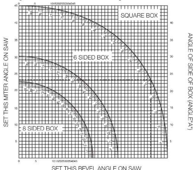
- The chart shown below will assist you in selecting the proper bevel and litre settings for common compound litre cuts.
- To use the chart, select the desired angle "A" (Fig. T) of your project and locate that angle on the appropriate arc in the chart. From that point follow the chart straight down to find the correct bevel angle and straight across to find the correct metre angle.
- Set your saw to the prescribed angles and make a few trial cuts.
- Practice fitting the cut pieces together. Example: To make a four-sided box with 25^ exterior angles (angle "A") (Fig. T), use the upper right arc. Find 25^ on the arc scale. Follow the horizontal intersecting line to either side to get the litre angle setting on the saw (23^) . Likewise follow the vertical intersecting line to the top
or bottom to get the bevel angle setting on the saw (40^) . Always try cuts on a few scrap pieces of wood to verify the settings on the saw.
WARNING: Never exceed the compound litre limits of 45^ bevel with

WARNING: To reduce the risk of serious personal injury, turn off and disconnect tool from power source before making any adjustments or removing/installing attachments or accessories. An accidental start-up can cause injury.
WARNING: Certain dust, such as oak or beech dust, is considered carcinogenic, especially in connection with wood-treatment additives.
Always use dust extraction.
- Provide for good ventilation of the work space.
- It is recommended to wear an appropriate respirator.
CAUTION: Never operate this saw unless the dust bag or ALT dust extractor is in place. Wood dust may create a breathing hazard.
CAITON: Check and clean the dust bag each time after using.
WARNING: When sawing aluminium, remove the dust bag, or connect the dust extractor to avoid the risk of fire.
Your litre saw has a built-in dust port 31 that allows connection to either a dust bag (33 mm nozzles) or direct attachment to the DEWALT AirLock (DWV9000-XJ) 45.
Observe the relevant regulations in your country for the materials to be worked.
To Attach the Dust Bag
- Fit a dust bag to the dust port 31.
To Empty the Dust Bag
- Remove dust bag from the saw and gently shake or tap the dust bag to empty.
- Reattach the dust bag back onto the dust port.
You may notice that all the dust will not come free from the bag. This will not affect cutting performance but will reduce the saw's dust collection efficiency. To restore your saw's dust collection efficiency, depress the spring inside the dust bag when you are emptying it and tap it on the side of the trash can or dust receptacle.
When vacuuming dry dust that is especially detrimental to health or carcinogenic, use a special dust Class M vacuum cleaner.
The dust port 31 on your litre saw is compatible with the DEWALT AirLock connection system. The AirLock allows for a fast, secure connection between the dust extractor hose and the litre saw.
- Ensure the collar on the AirLock connector 45 is in the unlock position. Align notches on collar and AirLock connector as shown for unlock and lock positions.
- Push the AirLock connector onto the dust port 31.
- Rotate the collar to the locked position.
NOTE: The ball bearings inside collar lock into slot and secure the connection. The litre saw is now securely connected to the dust extractor.
MAINTENANCE
Your DEWALT power tool has been designed to operate over a long period of time with a minimum of maintenance. Continuous satisfactory operation depends upon proper tool care and regular cleaning.
WARNING: To reduce the risk of serious personal injury, turn off and disconnect tool from power source before making any adjustments or removing/installing attachments or accessories. Be sure the trigger switch is in the OFF position. An accidental start-up can cause injury.
WARNING: If the saw blade is worn, replace it with a new sharp blade.

Lubrication
Your power tool requires no additional lubrication.

Cleaning
Before use, carefully check the upper blade guard, movable lower blade guard as well as the dust extraction tube to determine that it will operate properly. Ensure that chips, dust or workpiece particle cannot lead to blockage of one of the functions.
In case of workpiece fragments jammed between saw blade and guards disconnect the machine from the power supply and follow the instructions given in section Changing or Installing a New Saw Blade. Remove the jammed parts and reassembling the saw blade.
WARNING: Blow dirt and dust out of the main housing with dry air as dirt is seen collecting in and around the air vents. Wear approved eye protection and approved dust mask when performing this procedure.
WARNING: Never use solvents or other harsh chemicals for cleaning. In-metallic parts of the tool. These chemicals may weaken the materials used in these parts. Use a cloth dampened only with water and mild soap. Never let any liquid get inside the tool; never immerse any part of the tool into a liquid.
WARNING: To reduce the risk of injury, regularly clean the top.
WARNING: To reduce the risk of injury, regularly clean the dust collection system.
Optional Accessories
WARNING: Since accessories, other than those offered by DEWALT, have not been tested with this product, use of such accessories with this tool could be hazardous. To reduce the risk of injury, only DEWALT recommended accessories should be used with this product.
Range of saw blades available (recommended blades)
| Type of blade Blade dimensions Usage (diameter x bore x no. of teeth) |
| DT4310 series 40 216x30x24 For general purpose, ripping and cross-cutting of wood and plastics |
| DT4286 series 40 216x30x80 TCG for use with aluminum |
| DT4320 series 60 216x30x48 ATB for fine cutting of manmade and natural wood |
| DT4350 series 60 216x30x60 TCG for extra fine cutting of manmade and natural wood |
Consult your dealer for further information on the appropriate accessories.
Protecting the Environment
Separate collection. Products and batteries marked with this symbol must not be disposed of with normal household waste.
Products and batteries contain materials that can be recovered or recycled reducing the demand for raw materials. Please recycle
electrical products and batteries according to local provisions. Further information is available at www.2helpU.com.
Vice-President Engineering, PTE-Europa
DEWALT, Richard-Slinger-Strase 11
BEWAAR ALLE WAARSCHUWINGEN EN INSTRUCTIES ALS TOEKOMSTIG REFERENTIEMATERIALAAL
D-65510, Idstein, Germany
16.12.2022

d 45^ gering at hoger erler vandergering.

Toz Torbasini Bosaltmak Icin
- Toz torbasini testeden cikartin ve boşaltmak icin haffçé sallayin veya yurun.
- Toz torbasini toz portuna geri takin.

