ML1000EV - Garage door CHAMBERLAIN - Free user manual and instructions
Find the device manual for free ML1000EV CHAMBERLAIN in PDF.
Frequently Asked Questions - ML1000EV CHAMBERLAIN
User questions about ML1000EV CHAMBERLAIN
0 question about this device. Answer the ones you know or ask your own.
Ask a new question about this device
Download the instructions for your Garage door in PDF format for free! Find your manual ML1000EV - CHAMBERLAIN and take your electronic device back in hand. On this page are published all the documents necessary for the use of your device. ML1000EV by CHAMBERLAIN.
USER MANUAL ML1000EV CHAMBERLAIN
Manager, Regulatory Affairs
Chamberlain GmbH
Alred-Nobel-Str. 4
D-66793 Saarwellingen
February 2013
Babana P. Keckhoff
C
1 General safety guidelines 1
2 Intended use 2
3 Scope of supply 2
4 Product overview 2
5 Before you begin 2
6 Door types 2
6.1 Preparation 2
7 Tools required 2
8Assembly of the door opener 3
9Assembling the rail 3
10 Tighten the belt 3
11 Fitting rail to the drive 3
12 Installation of the opener 3
12.1 Centre of the garage door 3
13 Mounting header bracket 3
14 Attaching drive to header 4
15 Hang opener 4
16 Mounting door bracket 4
17 Attaching door arm on the trolley 4
18 Electrical connection 5
19 Connect illuminated push button 5
20 Installation of photocells .5
21 Connecting the opener 5
22 Program opener and test 5
23 Setting the limits 5
24 Test the Safety Reverse System 6
25 Program your remote / the Wireless push button (optional) .6
26 Special features 6-7
27 Operation of the door opener 8
28 Attach safety labels 8
29 Cleaning and maintenance 8
30 Cleaning 8
30.1 Maintenance 8
30.2 Replace batteries of the remote control 9
31Operator light 9
32 Disposal 9
33 Frequently asked questions 9-10 Diagnostic chart 11-12
34 Optional Accessories 12
35 Specifications 13
36 Service parts / Warranty 13
37 Declaration of conformity 13
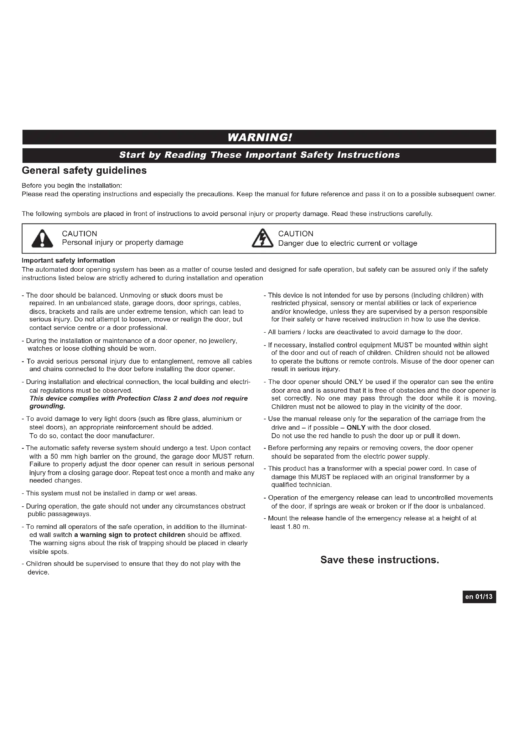
WARNING!
Start by Reading These Important Safety Instructions
General safety guidelines
Before you begin the installation:
Please read the operating instructions and especially the precautions. Keep the manual for future reference and pass it on to a possible subsequent owner.
The following symbols are placed in front of instructions to avoid personal injury or property damage. Read these instructions carefully.

CAUTION
Personal injury or property damage

CAUTION
Danger due to electric current or voltage
Important safety information
The automated door opening system has been as a matter of course tested and designed for safe operation, but safety can be assured only if the safety instructions listed below are strictly adhered to during installation and operation
- The door should be balanced. Unmoving or stuck doors must be repaired. In an unbalanced state, garage doors, door springs, cables, discs, brackets and rails are under extreme tension, which can lead to serious injury. Do not attempt to loosen, move or realign the door, but contact service centre or a door professional.
- During the installation or maintenance of a door opener, no jewellery, watches or loose clothing should be worn.
- To avoid serious personal injury due to entanglement, remove all cables and chains connected to the door before installing the door opener.
- During installation and electrical connection, the local building and electrical regulations must be observed. This device complies with Protection Class 2 and does not require grounding.
- To avoid damage to very light doors (such as fibre glass, aluminium or steel doors), an appropriate reinforcement should be added.
To do so, contact the door manufacturer. - The automatic safety reverse system should undergo a test. Upon contact with a 50~mm high barrier on the ground, the garage door MUST return. Failure to properly adjust the door opener can result in serious personal injury from a closing garage door. Repeat test once a month and make any needed changes.
- This system must not be installed in damp or wet areas.
- During operation, the gate should not under any circumstances obstruct public passageways.
- To remind all operators of the safe operation, in addition to the illuminated wall switch a warning sign to protect children should be affixed. The warning signs about the risk of trapping should be placed in clearly visible spots.
-
Children should be supervised to ensure that they do not play with the device.
-
This device is not intended for use by persons (including children) with restricted physical, sensory or mental abilities or lack of experience and/or knowledge, unless they are supervised by a person responsible for their safety or have received instruction in how to use the device.
- All barriers / locks are deactivated to avoid damage to the door.
- If necessary, installed control equipment MUST be mounted within sight of the door and out of reach of children. Children should not be allowed to operate the buttons or remote controls. Misuse of the door opener can result in serious injury.
- The door opener should ONLY be used if the operator can see the entire door area and is assured that it is free of obstacles and the door opener is set correctly. No one may pass through the door while it is moving. Children must not be allowed to play in the vicinity of the door.
- Use the manual release only for the separation of the carriage from the drive and - if possible - ONLY with the door closed. Do not use the red handle to push the door up or pull it down.
- Before performing any repairs or removing covers, the door opener should be separated from the electric power supply.
- This product has a transformer with a special power cord. In case of damage this MUST be replaced with an original transformer by a qualified technician.
- Operation of the emergency release can lead to uncontrolled movements of the door, if springs are weak or broken or if the door is unbalanced.
- Mount the release handle of the emergency release at a height of at least 1.80m .
Save these instructions.
2 Intended use
The device is intended for the opening and closing of garage doors (please refer to section 6 "Door Types").
The device is not meant for commercial use but solely for the use in private garage doors that are appropriate for a single household.
Any improper use of the drive could increase the risk of accidents.
The manufacturer assumes no liability for such usage.
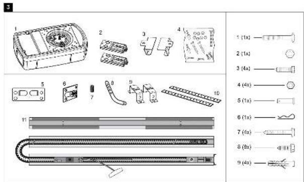
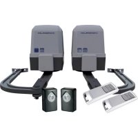
3 Scope of supply
Please check the supplied parts for completeness before starting the installation. Note: The numbering only applies to the corresponding section.
Parts overview (Drivehead):
-
Drive head 1x
-
Curved door arm 1x
-
Remote control 2x
-
Support bracket 2x
-
Support bracket 2x
-
Hanging bracket 2x
4.Hardwarebag 1x
- Rail 1x
Parts overview (Rail):
- Header bracket 1x
- Door bracket 1x
- Adapter for gear wheel 1x
Hardwarebag:
- Truss head screw
6x80mm1x - Safety cotter pin 1x
2.Lock nut M6 1x
7.Screw ST6x50mm
4x - Hexagonal head screw 4x
8.Screw ST6,3x18mm
2 × (4 ×) - Nut M6 4x
- Plug 4x
5.Bolt 1x
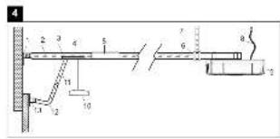
4 Product overview
This figure always offers you a complete overview of the ready-assembled system during the step by step installation of the system.
-
Header bracket
-
Power cable
2.Belt
- Drive head
3.Rail
-
Release
-
Carriage
-
Straight door arm
-
Connecting piece
-
Curved door arm
-
Mounting bracket
-
Door bracket
-
Support bracket
5 Before you begin
IMPORTANT NOTE
If your garage does not have a side entrance, an external emergency release should be installed. This allows for manual operation of the garage door from the outside during power failure.
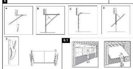
6 Door Types
A. One-Piece Door with Horizontal Track Only.
B. One-Piece Door with Horizontal and Vertical Track - Special door arm (E, The Chamberlain Arm™) and the Protector System™ required. See your dealer.
C. Sectional Door with Curved Track - See 20B - connect door arm.
D. Canopy door - Special door arm (E, The Chamberlain Arm™) and the Protector System™ required. See your dealer.
E. The Chamberlain ArmTM for use on door types B and D.
6.1 Preparation
First, check whether your door is balanced and in equilibrium. Open your door about halfway and let it go.
The door can now hardly change its position independently, but must remain in this position held by the spring force alone.
- The rail of the garage door MUST be connected securely and firmly to the supporting wall or ceiling above the garage door.
- Additional brackets and mounting rails (not included in the supply) might be required, if the your garage ceiling has a cladding, boards or similar.
- If your garage does not have a separate side entrance, an external emergency release (refer to section 34 "Optional Accessories") must be installed.
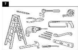
7 Tools required
Tool list:
Hacksaw
Ladder
Different drill bits for concrete
Marking pen
and(or wood (8,6,5,4.5 mm)
Pliers
Box wrench
Drilling machine
Water level
Hammer
Screwdriver
Ratchet 10mm / 13mm
Measuring tape
Assembly of the door opener

Important instructions for a safe installation.
Observe all assembly instructions.
Incorrect installation can cause serious injury.
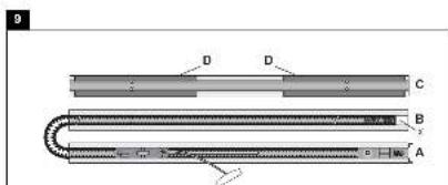
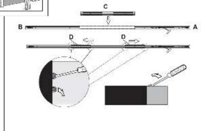
9 Assembling the rail
The rail is largely preassembled and consists of 3 parts.
The carriage, push rod, release handle, the guide pulley and the lintel bracket with belt tensioner are in the front part (A). The seating for the drive shaft and the sprocket are in the rear part (B). Lay the front and rear rail sections one behind the other.
Assembly of a 3-piece rail:
-
Remove cable ties that secure the belt.
-
Pull apart the two rail sections completely in order to create a gap for the middle section (C). This rail is designed in such a way so as to easily add the middle section. Slide the 2 connecting pieces (D) over the seams of the rail sections up to the markings. To secure the connecting pieces, bend the sheet metal lugs outwards with a suitable tool.
The assembly of the rail is complete.
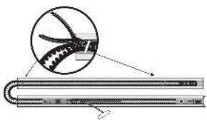
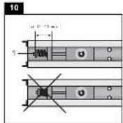
10 Tighten the chain belt
Tighten the belt of the rail until the spring (1) is compressed only by about half. The spring must compress and be able to bounce during operation.
11 Fitting rail to the drive
- Check if the belt is seated on the gear-wheel. If the belt has slipped off during assembly, relax the belt, lay it and tighten again.
- Turn around the rail (1) and completely put on the opener (3) with the gear side (2).
- Secure the rail on the opener with two mounting brackets (4) and the screws (5).
Optional:
To reduce the total overall length by 140mm the drive can be rotated by 90^ as shown in fig.11. This allows access and programming sideways.
Unscrew the switch and mount it to the designated second position. Remove the rubber plug in order to seal the cable exit.
Proceed with step 3.
This completes the assembly of the door opener.
12 Installation of the opener
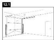
12.1 Centre of the garage door
Eye protection goggles should be worn for overhead work.
All available barriers / locks should be deactivated to avoid damage to the door.
To avoid serious injuries, remove all cables and chains connected to the door before installing the door opener. The door opener should be mounted at a height of at least 2.10m above the ground.
First, mark the centre line of the door (1). Draw a line to the ceiling starting from this point.
For installation on the ceiling, draw another line to the centre of the ceiling
(2) perpendicular to the door starting from this line.
Length approx. 2.80m
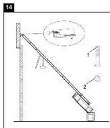
13 Mounting header bracket
Note:
Mount the rail max. 50mm above the top edge of the door. Depending on the door type, the top edge of the door is lifted by a few cm during opening.
A. Wall fastening:
Mount header bracket (1) centrally on the vertical centre line (2); thereby its lower edge lies on the horizontal line. Mark all holes for the header bracket. Pre-drill holes with 4.5mm diameter and fasten the header bracket with wood screws (3).
Note:
In case of mounting on a concrete slab / concrete header, the provided concrete plugs (4) and screws (3) should be used. Drill hole size in concrete: 8 mm.
B. Ceiling suspension:
Draw vertical centre line (2) further up to the ceiling and about 200mm along the ceiling. Attach header bracket (1) centrally on the vertical marking up to 150mm removed from the wall. Mark all holes for the header bracket. Drill holes with 4.5mm diameter and fasten the header bracket with wood screws (3).
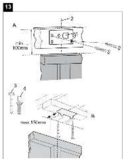
14 Attaching drive to header

It may be necessary to place the drive temporarily higher, so that the rail does not hit the springs in sectional doors.
The drive must either be well supported (ladder) or held firmly by
a second person. Put drive head on garage floor under the lintel bracket. Lift rail up till the holes of the fixing part and the holes of the lintel bracket are aligned. Insert screw (1) through the holes and secure with nut (2).
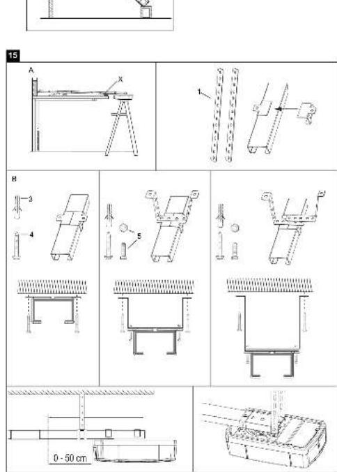
15 Hang opener
Fully open the door, put down door opener on the door (Fig. A).
Lay a piece of wood / cardboard on the marked spot (X).
The opener must be securely fastened to a structural support of the garage.
Three representative installations are shown (Fig. B).
Yours may be different. Hanging brackets (1) should be angled to provide rigid support. On finished ceilings, attach support bracket(not delivered) to a self-supporting structio-nal element before installing the opener. For concrete ceiling mount, use concrete anchors (3) provided.
On each side of opener measure the distance from the opener to the structural support (or ceiling).
Cut both pieces of the hanging bracket to required lengths. Flatten one end of each bracket and bend or twist to fit the fastening angles.
Do not bend at the bracket holes. Drill 4,5mm pilot holes in the structural supports (or ceiling). Attach brackets to supports with wood screws (4).
Lift opener and fasten to hanging brackets with screw and nut (5). Check to make sure rail is centered over the door.
Remove piece of wood / cardboard. Operate door manually.
If door hits the rail, raise header bracket.

Pay attention to a horizontal course of the rail along the ceiling. The distance can be adjusted by the given hole spacing.
Protruding ends of the ceiling fixture can be reduced if necessary.
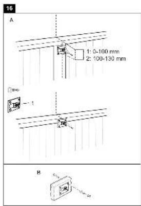
16 Mounting door bracket
Installation in sectional or one-piece doors:
The door bracket (1) has multiple mounting holes. Attach door bracket top centre on the inside of the door as shown. Mark holes and screw door bracket.
Mounting heights:
- One-piece or sectional door with a guide rail: distance to door top edge 0-100 mm.
- Sectional door with two guide rails: distance to door top edge 100-130 mm.
NOTE:
The attachment point on the door must be the frame or a stable place on the door panel. If necessary, drill through and screw (not included) together as shown in Fig. B.
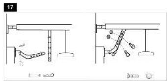
17 Attaching door arm on the trolley
The straight door arm is already pre-assembled.
Pulling the red handle the trolley will be released and can be moved manually.
-
The door should be fully closed if possible.
-
Pull down on the emergency release handle.
The lockout feature prevents the trolley from reconnecting automatically.
Push the green button on the trolley. With the next door movement the system will reconnect.

Mount the release handle of the emergency release at at height of at least 1.80m . Attach the yellow label regarding the release of the garage door opener (sticker) on the cord of the door handle.
18 Electrical connection

In order to avoid personal injury and damage to the device, the door opener should be operated only if such an instruction is explicitly stated in this manual. The power plug must always be accessible for the purpose of disconnecting the mains supply.
19 Install illuminated push button
Locate door control where the garage door is visible, away from door and door hardware and out of the reach of children. Mount at least 1,5m (5 feet) above the floor. Permanently fasten the caution label permanently to the wall near the door control as a reminder of safe operating procedures. There are 2 terminals on the back of the door control. Strip about 6mm of insulation from bell wire. Separate wires enough to connect the white/red wire to RED terminal screw and the white wire to WHT terminal screw. Fasten the door control to an inside garage wall with sheet metal screws (3) provided. Drill 4mm holes and use anchors (6) if installing into drywall. A convenient place is beside the service door and out of reach of children. Run the bell wire up the wall and across the ceiling to the garage door opener. Use insulated staples (5) to secure wire. Operation of the Door Control:
Press to open or close the door. Press again to stop the door while moving.
20 Installation of photocells (Optional accessory)
After installing and adjusting the door opener, photocells can be installed. The installation instructions are included with the photocells.
The optional photocells ensure that the door is open, or remains open, If people, especially young children, are in the door area.
By means of the photocells, a closing door is opened or an open door is obstructed from closing, if a person located in the door area interrupts the sensor beam.
Photocells are particularly recommended for families with young children.
21 Connecting the opener
Connect opener in accordance with local rules and regulations to a properly installed wall socket.
NOTE:
When the opener is switched on, the operator light is also turned on for 2.5 minutes.
22 Program opener and test

The door opener should only be used if the operator can see the entire door area and is assured that it is free of obstacles and the door opener is set correctly. No one may pass through
the door while it is moving. Before the first opening operation, check that all the facilities that are not needed are turned off. Remove all mounting aids and tools from the pivot area of the door.
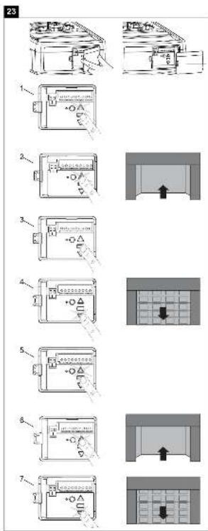
23 Setting the Limits
Travel limits regulate the points at which the door will stop when moving up or down. Follow the steps below to set the limits.
This operator is equipped with a two speed system that is automatically set by the software. Canopy or 1-piece garage doors will automatically run in slow speed to insure a safe operation according regulatory. Doors traveling shorter than 190~cm will run automatically slow.
INTRODUCTION
Your garage door opener is designed with electronic controls to make setup and adjustments easy. The adjustments allow you to program where the door will stop in the open (UP) and close (DOWN) position. The electronic controls sense the amount of force required to open and close the door. The force is adjusted automatically when you program the travel.
NOTE: If anything interferes with the door's upward travel it will stop. If anything interferes with the door's downward travel, it will reverse.
To watch a short instructional video on programming your new garage door opener use your smartphone to read the Code on this manuals back side or visit www.chamberlain.eu.
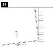
PROGRAMMING BUTTONS
The programming buttons are located under a removable cover on the back side of the garage door opener (see fig24).
- Press and hold the square Adjustment Button until the UP Button begins to flash.
- Press and hold the UP Button until the door is in the desired UP position. NOTE: The UP and DOWN Buttons can be used to move the door up and down as needed.
- Once the door is in the desired UP position press and release the Adjustment Button. The garage door opener lights will flash and the DOWN Button will begin to flash.
- Press and hold the DOWN Button until the door is in the desired DOWN position. Make sure the rail does not bend. NOTE: The UP and DOWN Buttons can be used to move the door up and down as needed.
- Once the door is in the desired DOWN position press and release the Adjustment Button. The garage door opener lights will flash and the UP Button will begin to flash.
- Press and release the UP Button. When the door travels to the programmed UP position, the DOWN Button will begin to flash. Note: IF the door does not travel to the UP position the travel limit programming failed. Begin again with step1. If door travel is too short please refer to section 33 "Frequently Asked Questions".
- Press and release the DOWN Button. The door will travel to the programmed DOWN position. Programming is complete.
24 Test the Safety Reverse System

The safety reverse system test is important. Garage door must reverse on contact with a 50~mm obstacle laid flat on the floor. Failure to properly adjust opener may result
in serious personal injury from a closing garage door. Repeat test once a month and adjust as needed.
OBSCTACLE TEST:
Place a 50~mm high obstacle (1) under the garage door on the floor.
Move door downwards. The door must reverse when it comes into contact with the obstacle. If upon contact the door stops, the door does not move down far enough. In this case repeat limit setting.
If the door reverses after contact with the 50~mm high obstacle, remove obstacles and open and close the door completely once. The door should not go back, if it reaches the door position "Closed". If it still reverses both limits must be reprogrammed.
OPENING TEST: Apply 20kg to the middle of the door.
The door should not open completely.
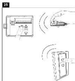
25
Program your opener and remote / the Wireless push button (optional)
Activate the opener only when door is in full view, free of obstruction and properly adjusted. No one should enter or leave garage while door is in motion. Do not allow children to operate push button(s) or remote(s). Do not allow children to play near the door.
Your garage door opener receives and one of the buttons remote control are pre-programmed. If you purchase additional remote controls, the garage door opener must be programmed to accept the new remote code.
Program the Receiver to Match Additional Remote Controls:
Using the yellow round button
- Press and release the yellow round button on the opener. The learn indicator light will glow steadily for 30 seconds (1).
- Within 30 seconds, press and hold the button on the hand-held remote that you wish to operate your garage door (2).
- Release the button when the opener light blinks once. It has learned the code. If the light bulb is not installed.
Now the opener will operate when the remote control push button is pressed. If you release the remote control push button before the opener light flashes, the opener has not learned the code.
To Erase all Remote Control Codes
To deactivate any unwanted remote, first erase all codes: Press and hold the yellow round button on opener until the learn indicator light goes out (approximately 10 seconds). All previous codes are now erased. Reprogram each remote or keyless entry you wish to use.
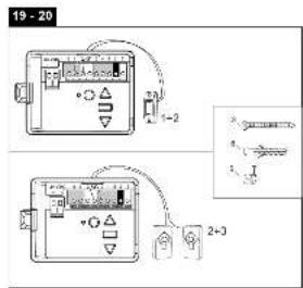
26
Special Features
A. Door within a door connection
Description of feature:
Locate auxiliary quick connect terminals. Remove wire bridge.
Insert bell wire into quick connect terminals 4 and 5.
B. Flashing light connection
Description of feature:
The Chamberlain flashing light can be installed anywhere.
Connect light leads to quick connect terminals 6 and 7.
C. Partial opening feature
Description of feature: The pedestrian, ventilation or pet opening position is an adjustable second stop position between the fully opened and fully closed position of the garage door.
Activate:
NOTE: Any time programming requires pushing two buttons simultaneously, make sure this is executed accurately. If other buttons than described will flash, briefly cut operator from current and start programming from the beginning.
- Move the door into to the desired partial opening position using the remote control or wallcontrol.
- Choose a non programmed button on your remote control.
- Push square button and UP button simultaneously for 3 seconds and wait for the operator light to flash. Then push the remote control button. To program an additional remote control start again with step1.
Deactivate:
- Move the door to the fully closed position.
- Push square button and UP button simultaneously for 3 seconds and wait for the operator light to flash.
D. Instructions for Auto-Close Feature
Description of feature: The Chamberlain Safety IR Sensors must be installed (required by EN60335-1-95).
Activate:
Push square and DOWN button simultaneously until the operator light blinks. 1 push UP button = 10 seconds, up to 180 sec. possible (18x) During countdown the down button flashes.
To complete programming push square button.
Deactivate:
Push square and DOWN button simultaneously until the operator light blinks.
To complete programming push square button.
Notes:
- The auto-close timer resets if the IR sensors are interrupted.
- In the partial open position automatic close is not possible.
- The garage door operator must have reached the programmed UP limit to activate the auto-close timer.
Troubleshooting:
Question: Operator will not work anymore without IR sensor.
Solution: Correct. IR sensors are mandatory once connected.
A full logic board reset is required.
E. OPEN, STOP or CLOSE programming of the remote control. Description of feature:
Each remote control button can be programmed to either OPEN, STOP or CLOSE the door.
OPEN:
Push yellow round button and UP button simultaneously until the led goes on. Now push a selected button on the remote control for OPEN only and wait for the operator light to flash.
STOP:
Push yellow round button and square button simultaneously until the led goes on. Now push another selected button on the remote control for STOP only and wait for the operator light to flash.
CLOSE:
Push yellow round button and DOWN button simultaneously until the led goes on. now push a third button on the remote control for CLOSE only and wait for the operator light to flash.
F. Keyless entry (requires 747REV wireless keypad):
Enter a 4 digit code of your choice to operate the door.
G. Temporary access (requires 747REV wireless keypad):
A temporary code can be programmed to allow limited access to the garage (by time or number of openings).
L. One button close feature (requires 747REV wireless keypad):
Without having the access code the door can be closed from any position (not opened).
N. myQ (requires 830REV gateway):
Allows operating your garage door opener via internet or a compatible mobile phone.
O. Garage Door Monitoring (requires 829REV Garage Door Monitor):
Features optical (by LEDs) and audible control of the status of your garage door. Allows closing your garage door from the place this device is installed.
P. Laser Park Garage Sensor
Photocells and laser park sensor required
Quick connection terminals 2 and 3
(available from around July 2013)
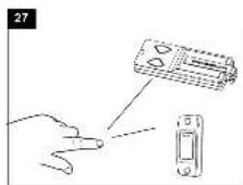
27 Operation of the door opener
Automatic opening / closing of the door:
The door opener can be operated using the following devices:
- Remote control: Press the button until the door starts to move.
- Wall switch (if this accessory is installed): Press the pushbutton until the door starts to move.
Manual opening of the door (by hand):

If possible, the door must be closed completely. Weak or defective springs can cause a rapid shutting down of the open door, which can lead to property damage or serious personal injury.
RELEASE: Briefly pull the red handle down. Then open the door by hand. Open close door without pulling the cable!
RECONNECT:
The lockout feature prevents the trolley from reconnecting automatically. Push the green button on the trolley. With the next door movement the system will reconnect.
Function sequence:
When operating the door opener by radio control or wall switch:
- closes the door when it is fully open,
- opens the door when it is fully closed,
- stops the door if it is opening or closing,
- the door moves in the opposite direction to the last completed move, if it is partially open,
- drives back the door to the open door position, if it hits an obstruction while closing,
- stops the door, if it encounters an obstacle during opening.
- Photocells (optional): By means of the photocells, a closing door is lifted up or an open door is obstructed while closing, if a person located in the door area interrupts the beam.
- THE MULTI-FUNCTION DOOR CONTROL (optional) Press the push bar (1) to open or close the door. Press again to stop the door.
Light feature
Press the Light button (2) to turn the opener light on or off. It will not control the opener light when the door is in motion. If you turn it on and then activate the opener, the light will remain on for 2-1/2 minutes. Press again to turn it off sooner.
The operator light switches on in the following cases:
- First turning on of the door opener (short)
- Power interruption (short)
- With each turning on of the door opener.
The light turns off automatically after 2 1/2 minutes.
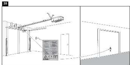
28 Attach warning labels (see fig. 28)
29 Cleaning and maintenance

Before any maintenance, cleaning and related maintenance work, the mains supply plug should be pulled out. Danger from electric shock!
Maintenance of the door opener
A proper installation ensures the optimum performance of the door opener with minimum maintenance. An additional lubrication is not required. Gross dirt accumulation in the guide rail may impair the function and must be removed.
30 Cleaning
Clean the drive head, wall switch and remote control with a soft, dry cloth. Do not use liquids.
30.1 Maintenance

Check the system often, especially cables, springs and fasteners, for signs of wear, damage or lack of balance. Do not use if repair or adjustment work must be performed, because an error in the system or an incorrectly balanced door may cause injury.
Once a month:
- Check automatic safety reverse again and reset if necessary.
- Operate door manually. If the door is unbalanced or stuck, please contact the service centre.
- Check for complete opening and closing of the door. Where appropriate, readjust limit switches and / or power.
Twice a year:
- Check the chain belt tension. For this, first disconnect the carriage from the drive. If necessary, adjust belt tension.
- Lightly lubricate the guide rail with standard grease (lubrication).
Once a year (at the door):
- Lubricate door roller, bearings and joints. An additional lubrication of the door opener is not required.
Do not grease the door rails!
Limit switch adjustment and force regulation:
These settings must be checked and undertaken properly during the installation of the opener. Due to weathering, minor changes can occur during operation of the opener that need to be addressed by a new setting. This can particularly happen in the first year of operation.
Follow the instructions for setting travel limits and force (refer to section 23 and 33) carefully and re-check the automatic safety reverse after each resetting.
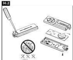
30.2 Replace batteries of the remote control
Battery of the remote control:
The batteries in the remote have an extremely long life.
If the transmission range decreases, the batteries must be replaced.
Batteries are not covered by the guarantee.
Please observe the following instructions for battery:
Batteries should not be treated as household waste.
All consumers are required by law to dispose of batteries properly at the designated collection points.
Never recharge batteries that are not meant to be recharged.
Danger of explosion!
Keep batteries away from children, do not short-circuit them or take them apart.
See a doctor immediately, if a battery is swallowed.
If necessary, clean contacts on battery and devices before loading.
Remove exhausted batteries from the device immediately! Increased risk of leakage!
- Never expose batteries to excessive heat such as sunshine, fire or the like!
- There is increased risk of leakage!
Avoid contact with skin, eyes and mucous membranes. Rinse the parts affected by battery acid with plenty of cold water and consult a doctor immediately.
Use only batteries of the same type.
Remove the batteries if the device is not being used for a long time.
Replacing battery:
To replace battery, turn remote control around and open the case with a screwdriver. Lift cover and lift control board below. Slide battery to one side and remove. Watch polarity of battery!
Assemble again from in reverse direction.
ATTENTION!
Danger of explosion if battery is replaced improperly.
Replacement only by identical or equivalent type (10A20-WH).
Operator light
The LED lighting has a very long life and is maintenance free.
The lens cover cannot be removed.
32 Disposal
The packaging is made from environmentally friendly materials. It can be disposed of in the local recycling bin. According to the European Directive 2002/96/EC on waste electrical and electronic equipment, this device must be properly disposed of after use to ensure the reuse of materials. The information on the possibilities of this waste disposal is provided by the local government or municipality.
33 Frequently asked questions
1. Door opener doesn't work with remote control:
- Is the opener connected to the power supply? If a lamp connected to the power socket does not turn on, check fuse or circuit breaker. (Some sockets are enabled via a wall switch).
- Are all door locks disabled?
See safety instructions!
- Check if remote control battery is lit.
Try operating with a new battery. - If you have two or more remote controls, of which only one works, check programming of the receiver.
- Is there snow / ice under the door? If yes, the door may be frozen onto the ground. Remove all obstacles.
- Perhaps the door spring is defective. This must be replaced by a specialist.
2. Transmission range of the device is too low:
- Is a battery inserted? Put in a new battery.
- Try radio control in the car at another location.
- The transmission range diminishes for metal doors, aluminium or metal panels.
3. Door reverses for no apparent reason:
- Is the door blocked by anything? Pull manual release and operate door by hand. In case of unbalanced or stuck gate, please contact the service department.
- Re-program operating force.
- Clear ice or snow in the closing area of the door.
- If the door reverses upon reaching the door position 'Closed', the limit switch must be set for this door position.
After completing every setting, the automatic safety reverse must be checked again:
An occasional resetting of the end positions is not unusual. In particular, the weathering can shift the doorway.
4. The garage door opens and closes by itself:
- Delete all remote controls and then re-programme them. See section 25.
- Is the remote control button jammed in position ON?
- Use only original remote controls! The use of third-party products leads to disturbances.
- The remote control button was pressed accidentally (pocket).
- Cable of the wall switch is damaged (remove for testing purposes).
- An accessory connected to the opener causes the drive (remove for testing purposes).
5. Door does not close completely:
- Re-programme stretch of way of the opener. Check for alterations in the mechanical components, e.g. door arms and fittings.
After each new setting of the door position 'Closed', the automatic safety reverse should be checked for function.
6. The door opens, but does not close:
- If installed, the photocells should be checked. If the LED at the photocells blink, the alignment should be checked.
- Check remote control or wall switch for function.
7. Operator light doesn't turn on:
- Open or close door. The light remains switched on for 2.5 minutes.
- Disconnect opener from the mains and connect again. The light comes on for a few seconds.
No power.
8. Operator light doesn't turn off:
- Disconnect the power from the mains supply for a short time and try again.
The 2.5 minutes are not yet over.
9. Motor hums and runs very briefly, but does not function:
- Garage door springs are defective. Close the door and disconnect from the opener by pulling on the handle of the carriage (manual release). Open and close door manually. If the door is properly balanced, it is held at each point of the doorway by the door springs alone. If this is not the case, contact your service centre.
- If this problem appears during the first use, the door may be locked. Deactivate door lock.
- Release opener from the door and try without door. If the door is fine, reprogramme operating force and stretch of way.
10. Opener works only in one direction:
- Door springs may be defective or the door is stiff in one direction.
- If the door is fine, re-programme operating power and stretch of way of the opener.
11. The belt rattles on the rail:
- Adjust the belt tension. The cause is usually a very tight chain/belt. The spring on the clamping device of the rail must not be compressed completely.
- The door runs unevenly and makes the drive vibrate. Improve door run.
12. Opener will not start due to power failure:
- Disconnect from the opener by pulling on the handle on the carriage (manual release). The door can now be manually opened and closed. If the opener is re-activated, the carriage also gets re-connected.
- If installed, the carriage is detached from the drive in case of power failure by an external emergency release from outside the garage.
13. Door reverses after the force was programmed:
- See if the rail bends. The opener requires a lot of power to move the door. Repair or install door correctly.
- Door is very heavy or in poor condition. Call a specialist.
14. Rail bends on the opener:
- Door is heavy, very heavy, stiff or in poor condition. Call a specialist.
- A swing of the rail while moving is a sign of an unevenly functioning door with constantly changing power requirements. Call specialist, possibly lubricate door. An additional suspension on the rail can be a remedy.
15. The opener „runs“ (audible turning of motor) but the carriage does not move:
The carriage is released from the opener.
- In a new installation: During the assembly of motor and rail, the pre-assembled adapter sleeve between the motor shaft and the rail was not installed. This sleeve is pre-assembled at factory, but can be removed. Standing behind the opener it can be observed whether the gearwheel turns in the rail or just the motor.
- In a new installation: The belt has come off from the gearwheel in the rail. Standing behind the opener, you can see the gearwheel.
- After years of use: Is the release defective or continuously disengaged?
- After years of use: The sleeve between rail and motor or the motor control gear is defective.
16. The door releases by itself from the carriage and stops:
- An external release that has been installed during a power failure should be checked whether it stretches and releases during the opening of the door. Watch the mechanism and reset if necessary.
- The handle of the release mechanism should not get caught in other items.
17. Setting the Force
The force setting button is located behind the cover at the operators backside. The force setting regulates the amount of power required to open and close the door.
- Open cover on the backside of the opener.
Locate the yellow round button (2). - Push the yellow round button (2) twice to enter unit into Force Adjustment Mode. The LED (3) (indicator light) and the UP button will flash. Push UP button. The operator will travel to the UP position learning the required amount of force. Once the UP limit is reached the LED and the DOWN button a start to flash. Push DOWN button. The operator will travel to the DOWN position learning the required amount of force.
Your garage door opener is programmed with self-diagnostic capabilities. The UP and DOWN arrows on the garage opener flash the diagnostic codes.
Diagnostic Chart
| DIAGNOSTIC CODE | SYMPTOM | SOLUTION | |
| Up Arrow Down Arrow Flash(es) Flash(es) | |||
| 1 | 1 | The garage door opener will not close and the light bulbs flash | Safety sensors are not installed, connected or wires may be cut. Inspect sensor wires for a disconnected or cut wire. |
| 1 | 2 | The garage door opener will not close and the light bulbs flash. | There is a short or reversed wire for the safety sensors. Inspect safety sensor wire at all staple points and connection points and replace wire or correct as needed. |
| 1 | 3 | The door control will not function. | The wires for the door control are shorted or the door control is faulty. Inspect safety sensor wire at all staple points and connection points and replace wire or correct as needed. |
| 1 | 4 | The garage door opener will not close and the light | Safety sensors are misaligned or were momentarily obstructed. Realign both sensors to ensure both LEDs are steady and not flickering. Make sure nothing is hanging or mounted on the door that would interrupt the sensors path while closing. |
| 1 | 5 | Door moves 6-8" stops or reverses. | Manually open and close the door. Check for binding or obstructions, such as a broken spring or door lock, correct as needed. Check wiring connections at travel module and at the logic board. Replace travel module if necessary. |
| No movement, only a single click. | Manually open and close the door. Check for binding or obstructions, such as a broken spring or door lock, correct as needed. Replace logic board if necessary. | ||
| Opener hums for 1-2 seconds no movement. | Manually open and close the door. Check for binding or obstructions, such as a broken spring or door lock, correct as needed. Replace motor if necessary. | ||
| 1 | 6 | Door coast after it has come to a complete stop. | Program travel to coasting position or have door balanced by a trained technician. |
| 2 | 1-5 | Replace logic board. | |
| 3 | 2 | Unable to set the travel or retain position. | Please refer to section 33 "Frequently Asked Questions", chapter 15 |
| 4 | 1-4 | Manually open and close the door. Check for binding or obstructions, such as a broken spring or door lock, correct as needed. If the door is binding or sticking contact a trained door systems technician. If door is not binding or sticking attempt to reprogram travel (refer to page 24). | |
| 4 | 5 | Opener runs approximately 6-8", stops and reverses. | Please refer to section 33 "Frequently Asked Questions", chapter 15 |
| 4 | 6 | The garage door opener will not close and the light bulbs flash. | Safety sensors are misaligned or were momentarily obstructed. Realign both sensors to ensure both LEDs are steady and not flickering. Make sure nothing is hanging or mounted on the door that would interrupt the sensor's path while closing. |
DIAGNOSTIC CODE
SYMPTOM
SOLUTION
Up Arrow Down Arrow Flash(es) Flash(es)
| 5 | 1 | Terminal 1+2 for wall control is short-ened longer than 4 seconds | Check wiring for push button if button is stuck and activated permanently. Remove wiring from terminal 1+2 on operator as test. Do not run push button wires next to high voltage wiring or in same conduit. |
| 5 | 5 | Low voltage | The operator has been shut off due to lower voltage supplied than allowed. If an external backup battery pack is installed, check if empty. If mains supply is used, check wiring and supply. |
| 6 | 1 | Maximum radio memory has been reached. | Maximum capacity for storage of remote controls has been reached. The first remote control or more previously programmed remote controls' codes have been replaced by a new one. To reset diagnostic remove power from the operator. |
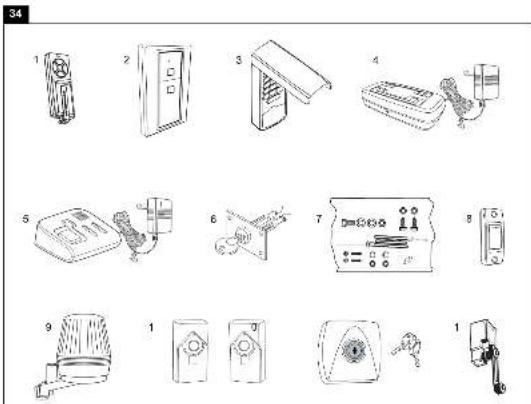
34 Optional Accessories
- TX4RUNI - 4-channel remote control
- 128REV - Wireless Wall Control 2-Channel
3.747REV -Keypad
4.830REV - myQ Starter Kit (Gateway + Photocells)
5.829REV - Garage Door Monitor
6.1REV -Quick release - 1702REV - Quick release
8.75REV - Wired push button - FLA-1LED - Flashing light
10.771REV -Photocells
11.41REV -Key switch (surface mount) - 16200LM - Door in Door contact
35 Specifications
Input Voltage. 230-240 VAC, 50 Hz
Max.Pull Force .700 N (COMFORT), 1000 N (PREMIUM)
Standby Power
(dooflyclosed)0.8W
Motor
Type. DC gearmotor permanent lubrication
Noise level. .54dB
Drive Mechanism...........Belt
Length of Travel....Adjustable
Opening speed, up to ...160 mm/s (COMFORT), 200 mm/s (PREMIUM)
Lamp. .On when door starts, off 2-1/2 minutes after stop.
Door Linkage ............Adjustable door arm. Pull cord trolley release.
Safety
Personal ...Push button and automatic stop in down direction. Push button and automatic stop in up direction.
Electronic........Automatic force adjustment
Electrical . . . . . . . . . . . . . . . . . . . . . . . . . . . . . . . . . . . . . . . . . . . . . . . . . . . . . . . . . . . . . . . . . . . . . . . . . . . . . . . . . . . . . . . . . . . . . . . . voltage push button wiring.
Limit Device .Mechanical RPM/Passpoint detector.
Limit Adjustment Electronic
Soft-Start/Soft-Stop...all
Dimensions
Length (Overall) 3200 mm
Headroom Required .......30 mm
Hanging Weight 12kg
Receiver
Memory Registers 180
Operating Frequency.....6-Band (433 MHz / 868 MHz)
SPECIAL NOTE: Chamberlain strongly recommends installing photocells on all garage door openers.
36 Service parts / Warranty
Please refer to www.chamberlain.eu or contact your local dealer.
Also refer to the available Warranty Book.
37 Declaration of conformity
Declaration of conformity
The listed automatic garage door opener corresponds to the applicable sections of the standards EN 55014-1 (2006), EN 55014-2 (2008), EN 61000-4-2 (2009), EN 61000-4-3 (2008), EN 61000-4-4 (2004), EN 61000-4-5 (2007), EN 61000-4-6 (2009), EN 61000-4-11 (2004), EN 62233 (2008), EN 300220-1 (V2.3.1),
EN 300220-2 (V2.1.2), EN 60335-1 (2010), EN 60335-2-95 (2004) in accordance with the provisions and all amendments to the European Directives 2004/108/EC, 2006/95/EC, 2006/42/EC and 1999/5/EG.
Model: ML700EV, ML1000EV
S./N: xxxxx000001 -xxxx99999
Manufacturer Chamberlain GmbH
Alfred-Nobel-Str. 4
D-66793 Saarwellingen
All technical archive data for the opener and the associated accessories are kept safe by Chamberlain GmbH and will be provided to the authorities on request if required.
B. P. Kelkhoff
Manager, Regulatory Affairs
Chamberlain GmbH
Alred-Nobel-Str. 4
D-66793 Saarwellingen
February 2013
Babana P. Keckhoff
C
Manager, Regulatory Affairs
Chamberlain GmbH
Alred-Nobel-Str. 4
D-66793 Saarwellingen
February 2013
Babana P. Keckhoff
C
Model: ML700EV, ML1000EV
S./N: xxxxx000001 - xxxxx99999
Manager, Regulatory Affairs
Chamberlain GmbH
Alred-Nobel-Str. 4
D-66793 Saarwellingen
February 2013
Babana P. Keckhoff
C
K. Laser Park garage sensor
Model: ML700EV, ML1000EV
S./N.: xxxx000001 - xxxx9999
Producent
Chamberlain
Alfred-Nobel-Str. 4
D-66793 Saarwellingen
Manager, Regulatory Affairs
Chamberlain GmbH
Alred-Nobel-Str. 4
D-66793 Saarwellingen
February 2013
Barbana P. Keckhoff
C
Oversikt over deler (drivhode):
1.Drivhode 1x
-
Festebøyle 2x
-
Handsender 2x
-
Opphengsjern 2x
-
Skinnefeste 2x
-
Skinne 1x
-
Tilbehorspose 1x
K. Laser parking garasjesensor
(fotocelle og laser parkeringssensor ndvendig) Hurtigkoblingsklemme 2 og 3 (tilgengelig ca. juli 2013)
Manager, Regulatory Affairs Chamberlain GmbH
Alred-Nobel-Str. 4
D-66793 Saarwellingen
February 2013
Babana P. Keckhoff
C
Manager, Regulatory Affairs
Chamberlain GmbH
Alred-Nobel-Str. 4
D-66793 Saarwellingen
February 2013
Babana P. Keckhoff
C
Marker (8, 6, 5, 4, 5 mm)
Model.. ML700EV,ML1000EV
S./N.: .xxxxx000001 - xxxxx99999
Producent Chamberlain GmbH
Alfred-Nobel-Str. 4
D-66793 Saarwellingen
Manager, Regulatory Affairs
Chamberlain GmbH
Alred-Nobel-Str. 4
D-66793 Saarwellingen
February 2013
Babana P. Keckhoff
C
Manager, Regulatory Affairs
Chamberlain GmbH
Alred-Nobel-Str. 4
D-66793 Saarwellingen
February 2013
Babana P. Keckhoff
C
Ta navodila obvezno shranite.
2 Namenska raba
(pri zaprith vratih) .0.8 W
Motor
Tip motorja .DC motor z gonioom s trajnim mazanjem
Raven hrupa .54dB
Vrsta pogona .zobati jermen
Dolzina poti vrat .nastavljiva
Hitrost odpiranja do 160 mm/s (COMFORT), 200 mm/s (PREMIUM)
Osvetlitev .vklopljena, ko se zažene pogon, izklopljena 2-1/2 minuti po ustavitvi.
Manager, Regulatory Affairs
Chamberlain GmbH
Alred-Nobel-Str. 4
D-66793 Saarwellingen
February 2013
Babana P. Keckhoff
C
Manager, Regulatory Affairs
Chamberlain GmbH
Alred-Nobel-Str. 4
D-66793 Saarwellingen
February 2013
Babana P.Kelkhoff
C
chata 6 x 80mm 1x 7. Parafuso ST6 x 50mm 4x
- Porca de seguranca M6 1x 8. Parafuso ST6,3 x 18mm 8x
3.Parafuso sextavado 4x 9.Bucha 4x - Porca M6 4x
5.Cavilha 1x
23 Ajustar as posicaoes finals
Comprimento (total) .3200 mm
Distancia necessaria do teto .30 mm
Peso suspenso 12kg
Receptor
Registo 180
2006/42/CEE e 1999/5/CE;
Modelo: ML700EV,ML1000EV
S./N: .xxxxx000001 - xxxxx99999
Hersteller
Chamberlain GmbH
Alfred-Nobel-Strasse 4
D-66793 Saarwellingen
Manager, Regulatory Affairs
Chamberlain GmbH
Alred-Nobel-Str. 4
D-66793 Saarwellingen
February 2013
Barbana P. Keckhoff
C
Manager, Regulatory Affairs
Chamberlain GmbH
Alred-Nobel-Str. 4
D-66793 Saarwellingen
February 2013
Barbana P. Keckhoff
C
Manager, Regulatory Affairs
Chamberlain GmbH
Alred-Nobel-Str. 4
D-66793 Saarwellingen
February 2013
Babana P. Keckhoff
C
Malli: ML700EV, ML1000EV
S./N.: xxxx00001 - xxxx9999
Valmistaja
Chamberlain GmbH
Alfred-Nobel-Strasse 4
D-66793 Saarwellingen
Manager, Regulatory Affairs
Chamberlain GmbH
Alred-Nobel-Str. 4
D-66793 Saarwellingen
February 2013
Babana P.Kelkhoff

Model: ML700EV, ML1000EV
S./N.: xxxx000001 - xxxx99999
Vyrobca Chamberlain GmbH
Alfred-Nobel-Str. 4
D-66793 Saarwellingen
Vsetky technické archivne udaje pre pohon a zodpovedajuce prislustenstvo je uschované firmou Chamberlain GmbH a na ziadost uradov sa da v pripadte potreby k dispozicii.
B.P.Kelkhoff
Manager, Regulatory Affairs
Chamberlain GmbH
Alred-Nobel-Str. 4
D-66793 Saarwellingen
February 2013
Babana P. Keckhoff
C
1 O6uue yka3aHnno texnke 6e0nacHocTn 2
2IcnoJb3OBAHHeNoHa3NaueHnO 2
3Obem noctabkn 2
4 O63op n3dennr 2
5Ipeed nauanom montaxka 2
6 Tnbl Bopot 2
6.1 PtoTobka 2
7 Heo6xoIIMble HnCTpyMeHTbl 2
8 MoHTaK IIpNbOda BOpOT 3
9 C6opka IHHbl 3
10HaTaeHne3y6aToRo pemn 3
11 CoeHHeHne IHHbI c npuBOdom 3
12 YctanOBka npBbOda Bopot 3
12.1 OnpeJeIeHne ueHTpa rapaKbIX BopoT 3
13 MoTax KpennenapxntpaBa 3
14 3akpenlenne npnboda Ha apxntpaBe .4
15 PoiBWeuBaHne npuBoDa 4
16 MoNTaX KpePJIeHnB BOpOT 4
17 3akpenJIeHne KpoHHTeHa BOpT Ha KaPeTke 4
18IopcoeHHeHneK3JKeKTpocetn 5
19 PtoKluoyHHe ocBeueHHo HacTeHHo KHOPIK 5
20 YctaHOBka foTopeIeHoro 6apbepa .5
21 PoiKlueyHne 6noka npuBoa .5
22 Perynipobka npOBepka BopoT 5
23 HacTpoiKa KOHcEbIX BbIKIOuChaTeIeI .5
24 PpOBepKa ABtOMaTnueckOrO oBpaTHoro XoJa No ycNoBnIO
6e3onacnoctn 5
25 PpOrrpaMMNPOBaHnpe paNooynpaBJeHnra /
HacteHHoK KhoKn paAnOynpaBHeNn (Onu) 6
26 CneuaalbHoe ochaueHne 6-7
27 YnpaBneHne npuBODom BopoT 8
28 KpenneHnpeDynpexkaioe 3naKa .8
29 OuchTka N TexHueckoe 6cbnykBaHne.8
30 Ouchka 8
30.1 Texnueckoe o6cnykBaHne 8
30.2 3aMeHa aKKyMnyTOpOB B nOpTaTnBHom
nyIbTe DnCTaHtioHHO ynpabHeHH 9
31 OcBeIeHne npBoda 9
32 Ytnnaaia. 9
33 YacTo BoaHnKaHouNe BonpocbI 9-10
Ta6nua dnaarHocTKn 11-12
34 DononHnTeIbHoe o6opuDobAHne 12
35 Texnueckne xapaKTepeCTNIK 13
36 3anactn /Iapantna 13
37 3aBbIeHHe O COOTBeTCTBmN 13
BHIMAHHE!
BAXHbIe YKA3AHnI NO MOHTAXy I NCNoJIb3OBAHNIO

O6zne npaBnla TexHnKn 6e3onacHocTu
Ipeen Hauajom MOHTaJa:
IpounTae, noxayncta, nHctpyKuIO no 3KnnyatauIN, INpeXe Bcero HxkeCneDyUOUIne npaBnna TeHNKn 6eONacHocTN. NHCtpyKuIO Heo6xoNMO coxpahntb nepeDaTbe BO3MOXHO CNeDyUOeMy BnaJeBtu.
Ipeed yka3aHnMn, npeDynpexdaIOUIMN O BepoTHocTn TpaBMnpoBaHn IIODee NII NOBpeKdEHm IMyIecTbA, NMeIeHb CneDyIOu
CNMBONJI. IoxKaJyIcTa, BHIMATEJIbHO npOHTaTe 3Tu yKa3AHNA.

OCTOPOXHO
TpaBMPOBaHne IIOe INI
NOBpeKdEHNHe IMyUeCTBa

OCTOPOXHO
Onachoctb nopaxeHHaJIeKtpnueckmM
TOKOM NIN HapjxHHeM
BaxKbIe yka3aHnNo TExHnke 6e3OnaCHOCTN
PnBOD BOPOT CNpoeKtnpoBaH IN PNOJEN NcblTaHnHa NpeDMeT HAdEeKHOCTN ynpaBHeHnO; OHO MOKeT 6bIb rapaHTnPOBaHO ToIbKO npn ycIOBm, ecnn BO Bpem MoTHaXhBIX pa60T n YnpaBHeHn TOHO BbINoHryIOrC, nepeuNCneHHbe Hnke yka3AHn NO TexHnke 6e3OnaCHOCTn.
-Bopota doJIKHbI 6bITb c6aHaHcnpoBaHbI. Bopota, KOtOpbIE He DBnraIOTcnn 3aeJaOT noDneKxat peMoHTy. RapaXhBIE BOPota, npYkHHbIM MexaHNm, Ka6eN, WKNbIb, KPOHUsTeHbI NmHbI HaxOJaTcN IO nOBbIeHHOH Hargy3KOi, YTO MOKeT CTAb TpNHyHOIN TReKeJIbIX TpaBM. He bTaTaeCbOCBo6OaNTb BOPota, cDBInHYbNX C MeCTa INN BblPoBHrTb, IyUwe o6paTInTeCb 3a NOMouBIO B cnyK6by TexHnHeckCOrO cepBnca INN K CneuNaIncTa m No rapaXhBIM BOPoTAM.
-Пи PMontaKe I TexO6cnyKmbaHnnpBbOda BOpOT He pa3peWaaTcHadeBaTb ykpaSeHn, Yacbl INI ODeXdy CBO6oHOro NOKPOr.
-Bo n36exaHne TaeKeIbIX TpaBM n3-3a HamaTbIBaHnI, nepeJ MOHTaxOM npBODa BOPOT Heo6xOIMO DeMOHTnpOBaT Bce NOcOeINHeHHbIe K BOPOTAM TPOCSbI NcENI.
- Pn MOtAkhbix pa6oTnx I NOKJIIOUeHn 3NeKTPuuecknx KOMNoHEHOB HeOxOJIMo co6IIOaTb DeNCTBHyOUIne MeCTHbIe npednncAHnno npoBeHeHIO CTPOITeNbHbIX IN 3NeKTPoMOHTAkhbIX pa6oT. DaHHoe yCTpOcICTBO OTBeuayet Tpe6oBAHNm 2Knacca 3auNTbI H Te Tpe6yEt
DONOHHTeJbHOro 3a3EmHeHn.
-Bo n36bexaHne NOBpeKdEHN BOPOT n3 OcO6o JERKx MATEpnaNoB (HaNP. CTeKNBOJOKHA, ANIOMHHN IIN CTaII) Heo6XoDMO yCTaHABnBaTb COOTBeTCTByIOUe YCNITeIN.ДЯ 3TORO o6paNTeCB, NOKaIyIcTa, K PON3BOJNTeJIIO BOPOT.
- ABToMaTnueckn 6oPbTHbI XoD BOpOT Heo6xOuMo npOBepaTb. PpN KOHTaKe T c npeTCTBnEM, Bo3BbIaIouMcraH aI yoBHeM 3eMnHa 50 MM, rapaKhBe BOpota OJXHbI OTbe3KaTb Ha3ad. PpN 3akpbBaHHn BOpOT HnPaBnHbO OTpErynIpoBaHbI pINBOd MoXeT CTaTb PnUHNHO TJeKbIX TeLeChbIX TpaBM. PpOBepkCy CneDuET NOBTopaTb pa3 B Mecau I npn Heo6xOuMoCTn BHocntb KoppeKtnpOBKn.
-ДанhoeобopydOBaHHe He DoJIxHO MOHTnPoBaTbC8 BO BnaxHbIX INN CbIpbIX NOMeUeHnX.
-Пин Экплугатугь Ворота He Должны ПеpeкpbiBaTb obшестveьыпуTN DBNIXEHA.
-ДЯн hamonhaHЯ O Heo6xOdMocTn 630nacHOrO ynpabIeHnry praOM co CBETaIeCn HAcTeHHoN KHOKnOc CneJyEt YCTaHaBnBaTb TaBnUky, HanomHaIOuYIO Heo6xOdMocTn 3aunTbI OT DeTeN. TaKKe B nOJe 3peHnra Heo6xOdmo YCTaHOBnTB TaBnUky, HanomHaHOuyo 0b OnaCHOCTn 3aueMJIeHnY.
- YTo6bI DeTn He IrgpaInCb C yCTpOiCtBOM 3a HmN Heo6xoDIMO npncMaTpNBAtb.
- DaaHoe yctpoiCTBO He npedHa3NaHeo IINI cNOJb3ObaHnIIOdbMn (B TOM YNCNE DeTBMN) C ORpAHueHHbIMN NCNXueCKIMN, OprAHOJIENTUeCKIMN, YMCTBeHHbIMN CTOOCBOHcTAMN ININ JIOdbMN, H NMeHOzMMN ONbTA N/INN 3HaHnE, ECNI TOJbKO OHN He HaxOJaTc NOd PnMCOTpOM JInCa, OTBeuHaOJIeO 3a INX 6e3OpaCHocTB, INN He NOLyUHnIOT Hero Yka3AHNA INCNoJIb3OBaTb yctpoiCTBO.
-Bo n36eKaHne NOBpeXeHnB OBOt Heo6xoDmO DeaKTHBnPOBaTb BCE mHeouIuecra 6nOKnPaTopbl /3anopbl.
-Bo3MOXHO,yCTaHaBJIbAeMbIyeyTPOJcTBaYnpaBJIeHnIIOJIKHbIMOHTPOBaTbCBA30He BNDIMOCTHNBOPOB TppeJEnAX HeDocraEMoCTnДЯTei.He pa3peWaiTe TeTAM BaIOBaTcBKnOHkAmn INyUcTPOJcTBAMINCTaHcUNHOHOrO ynpaBJIeHn.I3NoynOTpe6JIeHnEPINBODOM BOPOT MOKET PpNBecTK CepBe3HbIM TpaBMam. - PnBODom pa3peuaeTcY npabTb TOIbKO TOrda, KOrda noNb3oBaTeHIO BnHa Bc3 3OHa y BOpT, Bo3ne HIX HeT HNKaKx NpEaTCTBn, n EcIn npBOD npAunbHo OtperynpoBaH. He pa3peuaTc npoxoNTb uepe3 BOPTa, KOrda OHn eUe DnraTc. He pa3peuaiTe Detam Irpatb B6n3n BOpT.
- IcnoIb3yIte pyuhyo pa36noknpOBky TOnbKO dny OTOeDINHeHNA KapeTKn OT npBODa, n no BO3MOxHocTH TOJIbKO npn 3akpbITbIX BOPoTAX. He noIb3yItecb dny OTKpbITNry INN 3akpbITbNBOPOt KpaCHO pyKoRrKOi.
- Ipeed nauanom peMOHTbIX pa60I INI nepei cHrTneM 0bnIOBkn npBOD BOPOT HeoXoIMO OTCoeHNITb OT 3NeKTPoNTaHn.
- DaaHoe n3dJIne OcHaeHo TpaHcOpMaTOpOM CO CneUaNbHbIM KaBeJem. B cnyae NOBpeKDeHn KBAINuPPOBaHbI CneuaJIncT DOJIKeH 3aMeHNt b erHa opunHaNbHbI TpaHcOpMaTOp.
-Пи BкнючEHn abapHnHOn pa36knKupOBKn,В cnyae ecnOcna6nN INI CNOMaHbI npyKInHbI,INI ecnBOPTa He c6aJIaHCnpOBaHbI,TO OHMOrT HauTaH He KOHTpOJNPyEMoe DBIXKeHne.
PyKoTky abapnHOn pa36NOKpOBKn yCTaHaBnBaIte Ha BbICOT MHHmym 1,8M.
Даннай Инструкшия дожхна 6ытб obязателбно coхpaheha.
2 IcnoIb3OBaHne no Ha3HaueHnIO
YcTpoIcTBOp npedHa3Hauaetc DnO tKpbIBAHIN 3aKpbIBAHIN NOBemHBIX n CeKIOHHbIX rapaXbIX BOPOT B YacTHOM CekTope. YcTpoIcTBo He npEHa3HaueHO DnI pPomblJeHHORO npIMHeHIN, a NCKIOHTeNbHO DnI nCNoNt3OBaHIN Ha BOPoTAX YacTHbIX rapaXeIK, nCNoNb3yEmbIX DnI ONDHO DomOBlaJeHIN. NcNoNt3OBaHIn PpNBoDA He No Ha3HaueHIO MoKeT npNBecTN K HeCuaCTHom cyuAio. Ipon3BOIDTeNB He HecET OTBeTcBEHHocTN B Cnyae NcNoNt3OBaHIN He No Ha3HaueHIO.
3 KomnJIeKT nOcTaBKn
Ipeud Hauanom MOHTaxa npoBepbte, noxayuCTa, hanyue BCex DeTanei KOMnkeTa. PpimeaHne: Hymepaunr deTanei OTHOCNTcra ToJbKO K daHHoR rnaBe.
063op dTean
( npnBODHa rOIOBka):
8 MoNTaX npNBoDa BOpOT

BaxhIe yka3aHnI dIy HAdEHXoro MOHTaKa. Co6JIIOaIte BCE yka3aHnI dIy MOHTaXHbIX pa60T. HenpaBnIbHbI MOHTaX MoXe T npNBecTn K cepB3HbIM TpaBMam.
9 C6opka uHHbI
HnHa DnKHa 6bIb npDabapnteBHO CMOHTnpoBaHa, COCTn3 3
aacteB. B nepeDneuactn (A) pacnoNoXeHb KapeTka, TOnKaTeBna
TaHra, pyKoRTka abapmHo pa36NoKIpOBKn, OboDHO pONk, a TaKke
Opnhk kpoHtTeHc HataKHeTEm cenn. B 3aDneuactn (B)
pacnoNoXeHO KpennHeHne dny yctaHOBKn pInBoHO rO bana n 3y6UtaT
WeCTepHry. YIOXte nepeDHOIO N 3aDHOIO uactb nnHbOdy 3a dpYroN.
1.CHIMnTe KaBeJIbHbIe CTaKKN, KOtOpIbe QHKcPiyOT 3y6TuB peMeHb.
2. OToDBHbTe 06e qactn WInhTaK, YTO6bl MeKdy HMMN 6pa3Obaocb CBO6oHoe MecTo DnA CpeHNx 3JemeHTOB (C). UHa HCohCTpynpoBaHa TaK, YTO B Hee MOXHO CBO6oHOb BCTaBnTb CpeHNHe 3JemeHTb. BCTaBBte NOBepxCtIKOB qacteY WInhB 2 coeHNHTeJIa (D) Do MeTOK. JI
fHKcauM CoeHNHTeNBHX 3JemeHTOB 3arHNTe HApKy NoxDoRzIM
INCTpyMeHTOM MetaIIINueCKHe BblcTybl.
MOHTAK WInhB 3akOHyeH.
10 HataxeHne 3y6aTOro peMn.
HaTnHTe 3y6aTbI peMeHb HnHb HaToBko, TTo6bl npyKnHa (1) CkanaCb ToBko HanoNoBHy. PnAeknnyaTaUm OHa DoJnxHa npyKnHtB.
11 CoeHHeHne uHHbI c npBODom
- POBeBpTe, 306bI 3y6uTbI pEmHb 6bIa HaTeHa IeCTepHIO. Ecnn npn c6OpKe 3y6uTbI pEmHb COCKOUnla, To Heo6XoIMo OcnaBt, HAdTeN HAraHyTb CHoba.
- Pa3BepHnTe 1u (1), n BCTaBbTe DO KOHca B npNBOd (3) Toi CTopoHOH, rDe wecTepeH (2).
- 3aФИКСИРУТЕ WIINHY B INPINODE NOCPEДCTBOM DByx KpeIeXHbIX Cko6 (4) I BnHTOB (5).
OnuHaBHO:
Дяукорочи obseдлнь ha 140 MM, npINBOJ MOJOH CMECTNtB ha 90, KaK npEcdTaBHeHO ha pnc. 11. 3TO OTKpbIbAe TOCTyN I NO3BOJIaR e nporpamMnPoBaTb c 6OKOBO CTOpOHbI. Jnra 3TOrO ydaInTe
nepeKIOUaTeNb uYCTaHOBnTe eO Ha BTOPOI pEyCMOTpeHbI depKaTeNb. YdaNTe 3aNyUKN dNra 3aKnOpKn Ka6eNbHoro BbxOda.
3aTeM npOBecTn 3.
MOnTax npNBOda BOpOT 3aBepweH
12 YctaHObKa npNBoDa BOpOT
12.1 OnpeJeHne ueHTpa rapaXbIX BOpOT
PnBbINHeHn pa60 BblIe ypOBH rOIOBbl dIa3aUITbI rna3
HaDeBaIte OcKn.Bo n36ExAHne NOBpeKdEHHB BOPOT HeoXoHmO
deAKTInBPOBaTb BCE IMeHOuNEcB 6NOKpyHOuNE yCTPOiCTBa / 3anOpbl.
Bo n36ExAHne TReKeIbIX TpABM nepeD MOHTaXOM npIBoDA BOPOT
HeoBXoHmO DeMOHTnpoBAbB CeNOCoEOJIHHeHHBe K BOPOTAM TPOCbl N
ceII.PnBOD BOPOT ycTaHabJIbAetC h BaICote pN6I.2,1 M OT NoA.
Chaana npOOnKtne IINHIO ueTHPa BOPOT (1).NxCODI IN 30ToTouKn
npOOnKtne IINHIO do NOTOLKa.ДЯ MOHTaXoNo NOTOLKy npOToKtne NO
HanpaBHeHIO K BOPOTmNo CEHTpy NOTOJKA dpyrYIO LInHIO (2),
OTtanKBaRcB OT PnEbIDyuee. DnHa OK.2,80 M.
13 YcTaHOBka ONOPHOro KpOHSeiHa
YKA3AHNE: MoHTnPOBaTb 5HHy MaKcHMaJIbHO NIOTHO K BOPOTAM. MaKcIMyM 50 MM HAD cAmO BblCOKO TOUKO. B 3aBNCIMoCTN OT TINa BOPOT BepXHRA KPMKa BOPOT pN OTKpbIbAHm MOKeT NOHMaTbCRA Ha HECKOJIbKO CaHTImeTpOB.
A. YcTaHOBKa Ha cTeHy:
PnIOxNtE onOpHbIKpOHwTeH N OeHTpy BepTnKaJIbHOJ NHHN ceHTpa (2)PnI 3OTOM HNKHN Kpa KpOHwTeHa DOJXeH pOxODNTB NO rOp3oHTaNbHOJ LINHH. HaMeTbTe OTBepCTNA DN ONOPHOrO KpOHwTeHa. PpOCBepNTe OTBepCTNa DnAmETpOM 4,5 MM IN npKpeNtE onOpHbIKpOHwTeH camopezAMn DnA DepeBa (3).
PIMMEUAHHE: Pn MoTaxe Ha 6eToHHb I NToIOK/6eToHHyIOpeMbky Heo6xOdmo HcNoB3oBaTb DIO6eN dIg 6eToHa (4) I BNHTbI n3 KOMJIeKTA NoCTaKN. Pa3Mep OTBepCTna IIN CBepJeHn B 6eTOHe: 8 MM.
B. YcTaHOBka Ha NToJIOK:
Ipoeptnte BepTKaJIbHyIO JINHIO CEHTpa (2)do notoKna I daJe e no
noTOLKy np6I. Ha 200 MM. PpInOxNte Ha BepTKaJIbHyIO JINHIO CEHTpa
onOpHbI KPOHUsTeIH (1),OTCTyINB OT CTeHb HA 150 MM.HaMeTBe
OTBepCTnIgOnOPHOrO KPOHUsTeHa.PpocBepNTe OTBepCTnIg
dAmetPOM 4,5 MM n npIKpeITNe OnpHbI KPOHUsTeH camope3amn dJa
depeBa (3).
14 MoNTax npNBoDa

YTo6bI WnHa He cTaJIKNBaJnAc b C npyKnHaMm MHOROCEKUHOHbIX BOpT,MOKeT NpTepeBaTbcBpeMeHHO nIOJOXHTb PnIBoD HEMHO BblE. PtN 3Tom npINBOd HaO
NOMeCTnB Ha HAdEeKHyO onOpy (CTpeMAnky) nnn ero DoJnxH ydepKnBaTb BTOPO YeNoBek. IIOxKITE KOPNc npNbOda Ha non rapaKa nOg ONOpHBIM KPOHtEiHOM. PpINOHNMTe SiHNY TaK, qTO6bl OTBepCTnK pEnEHXo Yactn COBnAin C OTBepCTnMn Ha ONOpHOM KPOHtEiHe.
BCTABTe CKB03b OTBepCTnBnHT (1) nHaKpyTnte raKy (2).
15 HabeunBaHne npBoda BOpOT
OTkpOte nONHocTBbOBOTa, nONoxNtce CBepx npINoB OBOPT (pnc. A). POnIOXnTe B yka3aHHom MecTe (X) DepeBraKy /kapToH. PnIBoD dONJKeH 6bIb 3akpenneHa cMOHeCyUeM KOHCTpyKUnHOHOM 3JIemEnTe rapaKa. 3deCb npINoBOrTc TpI pInmepa MOHTaka (pnc. B), XOTBnHO He BO3MOxHO, YTO H N OIN H NIX HE COOTBeTCTByET B TOHOCTH BaWei CnCTMe. YTo6bl ObecNeuNTb JecKTKOCTb ONOpbl, NOBecHbIe KpenHnra (1) DOnKbHb IMeTb HAKNoH. B cNYaue noTOKOB C NOKpbITnEM (WtYkaTpyKa, o6NIzOBKa, o6ONoUka) Nepez 3akpenenHemmpINBOda Ha camOHeCyUeM KOHCTpyKUnHOHOM 3JIemEnTe CNEdyET O6OpyDoBaTb JecTKyIO MetaIINuYeCKyIO KOHCoNb (N3 KOMPiKeTA NoCTaBKn).ДЯ KpenHnRA K6eTOHOMy NOTOLyC nEduyET BOCNOB3OBAcbrA DIO6eJAMN IO 6eTOHy (3) N3 KOMPiKeTA NoCTaBKn. OTMepbTe C o6Ex CTOpOH OT npINoBa pacCToHnE Do cMOHeCyUeRO KOHCTpyKUnHOHORO 3JIemEnTa (NIn NoTOLKa).ObpeKbTe o6e Yactn NODBeCHORO KpenHnra DO Tpe6yEmo nnbl. CnIIIOuNTe KoHeu KaKdof KOHCoNl KpenHnra I daJe corHnTe INI pa3BepHnTe 3TN KOHcbl B COOTBeTCTBm C HyKhbIM YrIOM KpenHnra. N3beraTe Cn6aHnR KOHCoNl B MeCe T haoXdEHNr OTBepCTn KpenHnra. IpocBepNTe B cMOHeCyUeM KOHCTpyKUnHOHOM 3JIemEnTe (INN B NOToJIke) BeDuUne OTBepCTnRA DnAmETPOM 4,5 MM. Pnp NOMOUs Wypynob (4) CMoHTnpyTE KpenHnra HA COOTBeTCTByUoEe KOHCTpyKUnHOHOM 3JIemEnTe. POnHMnTE PtINoBD n 3akpennte erO Ha KOHCOnl NODBeCHORO KpenHnra C NOMOUsBIO BNhta, CTOnOPHOI Wa6bl I raIKN (5). Y6eDInTECB ToM, YTO peNbc paCnNoXeH NaB OPOtaM NocpeDInHe. Y6EPNTE Docky. PpINBeNTe BOPota B DvIXKeHne pykAMN. EcIn BOPota HATbikaOTc H peNbC, ycTaHOBITE KpenHnne XODoBOro peNbca Bblwe.

CneInte 3a TeM, YTO6bI UINHa npoxOuHa ropn3oHTaNbHO OTHOCInTeBHo NOTOnKa. PacCToHHe MOxHO peYIpopoBaTb 3a CET IMEOUxCXc OTBepCTN. Pn Heo6OUMocTN, BbICTyNaUQune KOUcBi NOTOnOuHOro KpePnEHH MoXHO yKOpOTNTb
16 MoNTaX 3JIeMeHtA KpeNJIeHnK BOpOTAm
YcTaHOBka Ha CeKIOOHbIe BOPoTa Hn Ha OJHOCTBOpaTbIe BOPoTA: KpenEHHa IIacTHHa K BOPoTAM (1) IMeET HeCKOJIbKO OTBepCTm IJa KpenIIeHn. PpInIOXKe TpeKEnKHyIO IpaCTHy K BOPoTAM BBepxY IO UHTpy BHYtpENHeI CTOpOHbI BOPoT, KaK NOKa3aHO Ha pncyHke. HAmTe OTBepCTN IN PpIKpyTNTE KpeKEnKHyIO IpaCTHy.
BbICota MOHTaxa:
- Ondoctbopatbe BOPoTnn CekuOnHhBc BOPoTa cOnHO HappaBnIOe nnHO: paccToHne Do BepxHe KpOMKn BOpOT 0-100 MM.
- Cekuohhbe BOpTa c DByMa HnPaBnaUcMM uHaMaPacctoHHe Do BepxHe KpOMKn BOpT 100 - 130 MM.
PpmeaHHe: MecTo KpeIeHnHa BOpTaX DoIxKHa 6bIb pAma IIN npOuHoe MeTo Ha NaHeJN BOpT. IpocBepnTe OTBepCTnK kAk Noka3aHo Ha pnc. B n3akpenTe BNHTAMn (Het B KOMIIKeTe).
17 KpenneHne pbuHaB OpoT K KapeTke
PpmoKpoHHTeIN BOPOT yxe yctaHOBnEH. OToeHNHe TKeapeTKy OT 3y6aTOro peMHra, nOraHyB 3a KpaCHyIO pyKoAry, n NepeDInbTe ee BpyHyIO.
PA36JIOKINPOBKA
- BopoTa DOJIKHbI 6bITb NO BO3MOXHOCTN 3aKpbITb NOnHOCTbIO.
- KpacHyIO pyKoRTky abapuHOn pa3bNOkpOBKn notaHTb BHN3. BJOKNPOBKA
MexHm3 pa36nOKnOBKn PpeoTbpaaet NOBtOpHy aBToMaTHueckyIO 6nOKnOBky KapetKn. HaxMnte Ha 3eJeHy KOHkNy Ha KapeTke N npc cIeMyOeM DnKHeHH BOPOT CnCTema CHOba 3a6nOKnpyetca.

YcTaHOBtpe pyKoTky abapuHnOH pa3bNOknpOBKn Ha BbcOte MmHmym 1,8 M. PpIKpeNTe K TpOcy pyKoTKn BOpT JeNTyO yKa3aTeNbHyO hKaNeKy O pa3bNOknpOBKe.
18 POncoeHHeHne K 3JeKtpocetN

Bo n36ekhaHne TpaBMnpoBaHnna IIOde H nobpeKdHnna yctpoCTBa npBbO BOpOT pa3peaTeB KKnOaTb, ToJIbKO ecIn B HactoIeM pykoBODCTBe DaHb NcHepNbIBaOHue
HnCTpykUIN.ДЯOTKIIIOUeHNAO T3NeKTpOcETN cTeBaR BUNKa DOJXHa HaxoNTbcraB CBO6OHO DoCTyHOM MecTe.
19 ПОДКЛЮЧЕНИЕ OСBE ueHHOн HaCTeHHOH KHOПКИ
Bce nepekniouateIIN KhoNk, yctaHaBnBaemIe Ha cTeHy,doJHKbI HaxoDntbcra B NoIe BNIMOCTN BOPOT, 3a npedenam30Hb HapabnIyOuixn HA Blicote Ok.1,5 M.PaDM C 3TmM BbIKIOUATEJMI NHeo6xOIMO NOMeCTNB TaBnHy, npdynpexJaIoUyO Heo6xOIMOCt 3aunTBi OT DeTe.Ha o6paTHoI CTPOHE BbIKIOUATEJN IMeTcI DBe BVHTOBle KNEMM.BChIMTE npimepHO Ha 6 MM N3OJIauIO CO 3BOHKO BORO npOBOD. OTeJIte PNOBA OOnIH OT dpyrO, YTObI npOBOD MOKHO 6blno NOKIIQUHTB K KEMME,a pNOBD K KEMME.CBeTAAnc HACTEH HbIKIOUHTB BbIKIOUATEJB: PnKpeNTe BbIKIOUATEJB K BYTpEHN CEte RAPaxa NocpeCTBOM CAMOHape-3hBX BnHTOB (3) n3 KOMNKeTA NOCTaKN. PInyCTAHOBKE Ha cTeHb, BOBeDEHbIE "cyXIM" CnOCobom CTPONTeBCTBA INN Ha 6BeONHbIE CTHeI, Heo6xOIMO npDeBapNTbHO PnOCBepNTb OTBepCTNA DaAMetPOM 5 MM N yCTaHOBNTb DIO6EN (6). UCTAHABINBaTb peKOMeHdyTCB03Ne 6OKOBORo BXOA B rapax Bhe PnpEDOB DOcRAeMOCT NeTe. PpONOXITE 3BOHKOBI npOBOD BDOJb CTHeI NO NOTONKY K npINBOy BOPOT. IJN KpeJIeHNr npOBDA NcONb3uyTe CkO6bCIO6eJMI (5). PpOTAHITE 3BOHKOBI npOBOD UpeE3 Ka6eNBHb KaHaI K KIeMME.
20 YcTaHOBka foTopeHOro 6apbepa (onzra)
ΦotopeneHbI 6apbep yctahabInBaetc nocne MOHTaKa n HactpoKn npBODa BOPOT. NHCPTyKUIN NO yCTAHOBKe HaxOHNCTB KOMNKeT NoCTABKn φotopeneHoro 6apbepa. DOnONHnTeNBHy BpOpeHbH BApBep o6ecneuBAET, YTObBi BOPOTa OCTaBAINCB OTKpbITbIMN, KOrda B 30He BOPOT haoJrTc NIOu, OOCeHNO DeTN. Ecnn IIOuN, HaxoJaunec B 30He BOpOT nepeceky T Lyu nepeDaTuKa, To 6laRogapra φotopeneHomy Bapbpye 3akpbBaIOUncsE BOPota NDoHMMAOTc BBepx INI 6IoKpyIOCTc OTKpbBaIOUncsE BOPota. UCTaHObKa φotopeneHoro 6apbepa OOCeHNO peKOMeHdyETc dna Cemei, rDe ecTb MaNeHbKne DeTN.
21 Повлочене блoka пивoda
IoiKIIIOHTe npIBO BOPOT B COOTBETCTBN C INHCTpyKUJMM N
DnpeKTINBaMn, DeiCTBYIOUIMN B MeCte YcTAHOBKN, K PO3eTKe C
3a3EMIAIOUM KOHTaKTOM, YcTAHOBJIENHOI CORIaCHO IpeDNICAHNM.
IPIMEUAHNE: Ppi BKIOUeHN npIBoHa Ha KOpOTKoe BpEm BAIOUaETcra
I NOCDBETKa pIBOda.
22 PerynipoBka n npOBepka BOpOT

PnBOD pa3pewaaTc BkIOUaTb ToIbKO, KOrJa NoJIb3OBATeIHO BnDA BC8 3OHa y BOpOT, Bo3ne HIX Het NIKAKNX npenrTCTBm I ecnn PnBOD npaBnIbHO OTPeryNipoBaH. He pa3pewaeTc
IpoxOHTbYepe3BOPoTa,KOrdaOnH eue HaxoJrTcB D BnXeHN. Ipeep NepBbIM BKNIOUeyHMeN pOBepeTbe, YTObbl OKnIOUeHb BCE yCtpoiCTBa,KOTOpbIe He nCNOJb3yIOTCa.Y6epNTe N3 30HbI ONyCKaHN BOPOT BCE MOHTaXHbIe PnCnOCOJIeHn INHCTpyMeHTbl.
23 HactpoIka KOHeuHbIX NOLOXeHn
KoheHbIe NOLOKeHn - 3TO NOLOKeHn, B KOTOpbIX OCTaHaBnBaIOCTc BOPota, KOrda OHn DnBKyTcB BExp HnBn3. BblOnHIne CneDyUOuine 3AnbI pIporpaMMNPOBaHnДЯ NaCtpoKIN KoHehXIOLOKeHn. PpNBOD OCHaSeH DByM RAckocCTaMn. PporpaMMHOe ObecneueHne npIBoDA npri pIporpaMMNPOBaHn ABTomAtNuCeCKn Bbl6nPaet NOnxOJaUcCKOpcTb. OnpOKnDbBaHouuceCRA BOPota n ODHocTBopCuATBe BOPota DBVaIOTcA BAtOMaTHueCKn PpeDnCaHHbIM O6pa3OM Ha MaJIo CKopoCTN. BOPota, YbKa KapTeKa KOpOye, Yem 190 cm DnBraIaoCT MeJNeHNo.
BBEDEHNE:
3NeKtpoHnka pa3DbNkKn rapaXhBx BOpOT cKOHCTpynpObaHa TaKIM 6bap3OM, YTO6bl BCE HAcTpoKn, KaK, HanpImep, HAcTpoKa KOHeHbIX NOJIOKeH N OTKP n 3AKP, 6bln ynpOeHbI. Pn 3Tom 6IOKn ynpabJeHH AToMaTneckn peRNCptpuyOT Heo6xoDmble ycHnna, Heo6xoDmble dnn pINBOda nI DocTNKeHn KOneHbIX NoJIOKeHn.
YKA3AHNE:
PnIIO6OBIpenTCTBn BO BpeMa IOnbema BOPoTa OCTaHaBnBaHOTc. PnIIO6OBIpenTCTBn BO BpeMa ONyckAnBaBOPoTa DnBraKOTc H3aJ. NocTe caiT www.chamberlain.eu INN OTOCKAnpye Tc NOMOuCBOero CMaprfoha paonoloxKeHHb Ha obaTHo CTOpone pykoBoDCTBa KOD, dIpaIOcMOtpa KopoTKoro BnDeo, KaCAHOeOra PaobToHOBpA3DbNKn rapaxhblx BOPoT.
KHONKINPOTPAMMIMPOBAHNA:
KhoNKn nporpaMMnpoBaHn paCIONoXeHbHa CbeMHoN KpbIWe Ha 6oPaTHo CTOpOHe npBODa (CM. pnc.24).
- HαkaTb n ydepKnBaTb HαkaTo npraMoYroIbHyIO KhONky nporpaMMnpoBaHna (Mexdy KhoNkAmN OTKP u 3AKP) do toro MOMeHTa, KOrDa NaHcHET MuraTb KhoNkn OTKP.
- HaxaTb u yedeKxBaTb HaxaToT oTbKO KhoNkY OTKP do DocnkeHn Tpe6yemoro KOHeHoro noNoKeHn OTKP. YKA3AHIE: C NOMoBIO KhoNOK OTKP u 3AKP MoKHO ouHb ToHo peryIInpoBaTb INN KoprKeTnPoBaTb KOHeHbIe NoNoKeHn.
- KaK TOnbKO BOpOa OKaKyTcB Heo6xOdNIMOM KOHeyHOM NOIIOKeHNOTKP, NOBtOpHO HaxMnTe npmoyrObnHyIO KhoNky npOrpaMMnpOBAHNA.OcBeueHne npNbOda 3AmraeT, IN KhoNka 3AKP NaHET Mrtarb.
- HaxaTb N ydepKnBaTb HaxaToT ToBko KhoNky 3AKP Do DocnKeHn Tpe6yemoro KOHeuHOro NoNoKeHn 3AKP. YDocToBepeBtecb, YTO Bbl HeaNeKO OTBexaNN Nnn NsHa N3OrHyTa BBepx. YKA3AHNE: C NOMOUsbIO KHONoK OTKP N 3AKP MoXHo OueHb ToHOp perynipobAtb Nnn KoppeKTnpOBaTb KOHeuHbIe NoNoKeHn.
- KaK TOnbKO BOpOa OKaKyTcB Heo6XoDUMOM KOHeuHOM NIOJKeHHN 3AKP, NOBTOpHO HauKMITE npMoyrOJIbHyI OKnIy IpoIpaMMIpOBAHn. OcBeueHne npNbOda 3amIraeT, IN KhoNka 3AKP HaHHT nobTOpHO MInrTaB.
- Haxmnte Ha KhoNky OTKP. Pnp DocTnxKeHn BopoTaMn 3aIporpaMMnpOBaHHoro KoHeuHOro NIOxKeHn OTKP, KhoNka 3AKP NaHT MraTb. YKA3AHNE: EcIn BOPota He ocTaHaBJIbAHO TcB KOHeUHOM NIOxKeHn OTKP, nporpaMMnpOBaHne He ydaNoCb. NobTopnte BCE waRn, HauHna c Waara 1. EcIn BOPota DnKyTcRe HeOcTaTOUHO DaNeKO, npOHTte B pa3dene 33 "Jacto 3aDaBaemble Bonpocbl".
- Haxmte Ha KhoNkY 3AKP. Tenepb BopoTa DnKyTcK 3aIporpaMMPOBAHHOMy NonoKeHIO 3AKP. PporpaMMPOBaHne 3aBepseHo.
24Проверка abTomatnueckoro obpaTHoro xoda

ABTOMaTneckn 06paTHbI XoD BOpOT Heo6XoDMIO npOBepraTb. PnKoHTaKTe C npenrTcBHeM, BO3BbIaIOUIMCraHd yPoBHem 3eMn Ha 50 MM, rapaxHbIe BOpTa DOJXHbI BO3BpaAaTbcra Ha3aH. HenpaBnBHo OtperyNpObaHHbI npBOd MoKeT cTaTb
npuHNOI TRAeJIbIX TEJIeCHbIX TpABM No pnpHMe 3aKpbIBaHNB BOpOT. IpoBepKy cJeMyET NOBTOrPaTb pa3 B MeCra N npn Heo6XoDmOCTN BHOcTN KoPekTHIpOBKn.
PpOBepKa Ha KOHTaKT C npenTCTBHeM:
Nojoknte Ha noi noi rapaxhblm BopoTaM npenrTcBne (1) BBICOTO 50 MM.
Onyctte BOPota. PnKoHTaKe C npenrTcBHeM BOPota DOJIKHbI OTBExaTb H3aI. Ecnn PnKoHTaKe BOPota OCTaHaBnBaHOCT, 3TO 3HaUHT, YTO OHN He DOctaTOHO ONyCKaIOCTBHN3. B 3OTm CNyae HeOBxOJIMO 3aHOBO 3AnporgammmPOBaTb 06a KOHehBX NIOJOXEHNI.
Ecnn nocne KOHTaTc npenrTcBnEM BbICToI 50 MM BOPoTa OtBe3KaIO T ha3d, y6epTe npenrTcBnE uOdn pa3 nonHOCTbO 3akpoITe NOTKPOITe BOPoTA. BOPoTa He DOJKNHbI OtBe3KaTb Ha3ad, KORda OHN DOCTNHyT NOJOKHeHHra "3aKpIbTO". ECnn OHN BCJe OE OtBe3KaHO, O6a KOHeHbIX NOJOKHeHHa DOnXhbl 6bIb 3aHOBO 3anporpaMMPOBaHb.
PpOBepKa Ha oTKpbIbAHnE: PpIIOxNte K cIeHTpy BOpO Tycnne B 20 K. Bopota He DoJXHbI NODHMATbcR.
DnarHOCTNKa HeNcnpaBHocTeN:
Ipo6nema: PpB0d 6oNbwe He pa6oTaet 6e3 foTopeHoro 6apbepa.
PeueHHe:OTcyTCTBHe HeNCnPaBHoCTeI. PpaBnIbHo. FTopeJeHbI 6apbep, KaK ToJIbKO OH OJHaXDbI BKIOuHTcR, Heo6xOIM B 063aTeJIbHom nopAKe.
E. 3aeneCTBOBAHne KHOJOK NOpTaNBHOrO NepeJaTcNkA dNn OTKPbITnR, OCTAHOBa n 3AKPbITnR OncanHe cyHKun:
KaJdA KONka NopTaTnBHO nepaTaYnKa MoKet 6bITb 3anporpaMMnpoBaHa Ha KomaHdbI 3AKP, OCTAHOB n 3AKP. OTKP:
OndOBpemHeHn HaxaTb JxenTyIO KONKy nporpaMMnpoBaHn I KNKny OTKP Do BKNIOueHn CBeToNDoA. TeNepb Ha nopTaTMBHom nepeDaTuKe HaxaTb KONKy, COOTBeCTByIOUyIO KOMAnDe OTKP, n NOdoXdaTb Do HauJaM MraHn OCBeUeHn PnIBOda. OCTAHOB:
OdHOBpeMeHHo HaxKaTb KeNtYIO KHOIky npOrpaMMIpOBaHHn I npRMOyToBHyIO KHOIky npOrpaMMIpOBaHHn DO MOMeHTa BKIOueHHn CBETOHOda. HAXMnTe Ha KHOIky Ha npTaTHBHom NepeDaTuKke COOTBeCTByIOuYIO KOAmHe OCTAHOB, INoDOxJnte Do hauJa MIRHaHH oCBeUeEHn npIBoDA.
3AKP
OdHOBpeMeHHo HaxaTb JeNtYIO KHONKy nporpaMMnpoBaHnry IN KONKY 3AKP Do BKNIOueHnCBeToNDNoA.
TenepbHa npTaBHom nepeDaTuKe HaxaTb KhoNky, COOTBeTCTByUOyIO KOMaHne 3AKP, INoOxJaTb Do HaaJa MIna HnraHnocBeueHnnpuBOda.
F. NporpammmpoBaHne paAnoynpaBnmeMoN cnCTEmbI DocTyna 6e3 KJIoua (ToIbKO c paAnoynpaBnmeMbIM KOOBbIM 3aMKOM 747REV):
IcnoIb3yIte BOpTa C NmHbIM KOdom n3 4 uΦp.
G. BpeMeHHbI DoCTyI (ToIbKO c paAnoynpaBnEMyIM KOIOBbIM 3AMKOM 747REV):
BpeMeHHbIKoDIIORpaHnueHnHO DocTyBaRapax (orpaHnueHbIe BO BpeMeHN IIN ORpaHnueHbIe NO KOJInuEcTBy npOceCbI OTKpbIbAHNIA) MOKeT IpOrpaMMIpOBaTbcra.
H.ФункцяЗakpbibahnnoOTdnelbHOKNKONKOI (TOnbko cpaNoynpaBnREMbIM KOIOBBIM 3AMKOM 747REV): Be3 KODa DocTyna BOpTa MOryT 3AkpbITbcra N3 IIO6Oro NOIOKeHHA (He OTKpbIBaTbcra).
I. myQ (ToIbKO c 830REV INTEPHT INTEPpeHCOM, Gateway): IosBONReT kCNnlyaTnpoBaT rapaxHbIe BOPota uepe3 INTEPHT nIO COBmecTmbl MOuNbHbI TelefoH.
J.Pene rapaxhbx BOPOT (TOnbKO pene rapaxhbx BOPOT 829REV): o6ecneuBaET ONTuYeCKN (C NMOUcBIO CBeToIDNoDOB) IN 3ByKOB0I KOHTpOJI bIIOXKeHn BOpOT. BOpota MOrY 3aKpbBaTbcra TaKke C NMOUcBIO 3TOrO yCTpoiCTBa
K.「rapaxhblnla3epHbI npkoBOuHbI daTtHK
(Heo6xOIMCBeTOB0BapbepnIa3epHbI napKOBOHyI daTtIK) KJIeMMbI dIg bIcTporo coeINHeHIn 2 n 3 (doCTyTHIO pPIMepHO c HONr 2013r.)
27 UnpaBJIeHne npIBoDom BOPOT
ABTOMaTnueckoe OTkpbltne/3akpbltne BopoT:
PpNBOD BOPOT aKTHBnpyeTc npn nmoOnn cneDyioux ycTpoNCTB:
- IopTaTnBhB npeDaTnK: HaxmMaTe KhoNkY, noka BopoTa He HaHyT DnHexHe.
- HacTeHHbI BblKIOUaTeJIb (ecn3O o6OpyIOBaHHe yCTaHOBJIeHO): Haxmaite KHOIOuHbI BblKIOUaTeJIb, noka BOPOTa He HaHyT DINKeHne
OTkpBITne BOPOT BpyHyIO (pyHoi pexm):
No BO3MOXHOCTN BOPoTA DOJNKHbI 6bITb NOHOCTBIO 3aKpbITbI. Ocna6JIeHNbIe NII NIOJOMAHHbIe npyXnHbI MOrYT npOBOUPOBaTb 6bICTpo naJeHne BOPOT, YTO MOxET pINBECTN
K NOBpeXdeHIO HmUeCTBa NJI TpaBMnpoBAHIO JIOJe.
PA35JIOKINPOBAHNE: KopoTko notaHyTB BnH3 3a KpaChyO pyuKy. 3aTeM OTKpbIb Tb BOPoTa pyKaMn. He OTKpbBaIe/3aKpbBaIe BOPoTa 3a Tpoc!
BLOKIOPOBKA: MexaHm3 pa3bIOKIpOBKn npedToBpaAaet NOBtOpHyo aBTOMaTneCckyio 6bOKIpOBky KapeTkN. HaxMnte Ha 3eNeHyIO KHONKy Ha KapeTke I npi CneDyUoem DnBKeHn BOPOT, CnCTema CHOba 3abokpyetc.
Функюнрованe
PnAaBauPiBbOaBOpC NOMOcIyNtTa DuctaHNOHOrO ynpabHeHH HAcTeHHORo BkIOuAteIa:
-BopoTa 3aKpbIbAHTcR,ecIN OH6blN NOJIHOCTbO OTKpbITbI;
- BOPOTA OTKpbIBAHOCTCA, ECNI OHN 6bIIIN NIOHOCtBu 3aKpbITbI;
- BOPoTaOCTaHaBJIbAIOCTc,ecnOHONOTKpbIbAioTcNIN3AkpbBaIOCTc;
- BOPoTa DnKxTyC8 HnPaBnEHH nPoTHBONIOXHOM NOcNeHEmy BbIOnJIHeHHOMy DnKxKeHHO,ecNJ OHN OTKpbITb YAcTNoHO;
- BOPoTa BO3BpaUaHOTcHa3aD B OTKpbIToe NIOXKeHne BOPoT,ecn npN 3aKpbITn OHn HaTKHyInCb H nppeTCTBHe;
- BOPoTA OCTaHABINBAIOCTC, ECNI PnO OTKpbITN OHN BCTpeTNI npenrTCTBNE.
-ΦOTOpENEHbB 6apBep (DOnONHnTeNbHo):Ecnn IIOu HaxOJaUneC B30He BOPOT npecekyT Lyu nepeDaTuKa,To 6laRoApa φOTOpENEHOMy 6apBepy 3akpbBaHOUneCBAPOTa NOHMaOTcB BBepx INI OTKpbBaHHe BOPOT 6nOKpyETc.
- YHNBEPCAJIbHA HACTEHHA KOHCOJIb (OuioHaJIbHO) HaMMte OIN pa3 Iaor OTKpbIbAHn / 3akpbIbAHn BOPOT Ha KhoNky (1). IIra octaHOBKn DInkKyUxxCBa BOpOT HaxKaTb NOBTOPOHO.
UnpaBHeHneOCBeSeHnEM
Tbbl BkIOuHTb NIN BbIKIOuHTb OCBeSeHne npIBoHa, HaxMnte
BbIKIOuTeJIb (2) C NaIINcIbO LIGHT. KorDa BOpTa OTKpbBaIOCTcN INI
3aKpbBAIOCTc, 3OT BbIKIOuTeJIb He OKa3bIBaEt BnIAHHe Ha OCBeSeHne
npIBoDA.
EcNbl BkIOuAeTe OCBeSeHne N 3aTeM aKTINBpYte TnpIBoD BOPt, TO
CBET RopIT eEe B TeeHHe 2,5 MHN. INaToro YTObbl BkIOuHTb
OCBeSeHne paHSe, HaxMnte BbIKIOuTeJIb eEe pa3.
Iopcbetka npBbOa BkHouaETcB CneDyUox CnyaX:
- NepBoe BKNIOUeHne npINBOJa BOpT (HeHaDoJIro)
- OTKNUeHne noaTuKa (HeHaJIoIro)
3.Пи Кждом BKIOUChEN IN pINBOda BOPOT
Yepe3 2,5 MHyTb CBET ATOMaTHUeCKN BbIKHIOaETc.
28 Kpenenne npeynpekaoero 3naka (Pnc. 28)
29 OuNCTka n TexHnueckoe obcnyxNbAHne
IpeKaKdbIM npoBeDeHem pa60T no yxOy, ouHcTke I TeXo6CnyKunBaHHIO He6xOJNMO BbITrNBaTB CeTeByO BNkky. Onachocb nopakHeHH 3JeKTPnueckm TOKOM!
TexnuecknyxOa3a npBODOM BOPOT
BbIOnHeHHhe HaJIeKaUIM Oba3OM MOHTaXHbIe pa6oTbI o6ecneayat ONtHMaIbHyIO FyHKUHOHaIbHocTb PnIBOa BOPOT Pn MNHMaIbHbIX 3aTpatax H aTexobcnykBaHne. DOnOpHNTeIbHra CMa3ka He Tpe6yETc. He6xOIMMo ydaIaTb KpyNbIe YacTnKr Ipr3n, NonaAIOuNe B XoOBOUYu SHHy n HapuuaIoune eepa60Ty.
30 OuNTka
Kopnyc npBoda, HacTeHHb BblkUoyateIb n NopTaTnBhI nepeDaTtK OunuBaT ToNko MmKo, cyxO TpRKnO. He nCnoNb30aBt KnDkoCTb.
30.1 TexHnueckoe o6cIyXnBaHne
Kak moxho yuue npobepnre obopyoBaHne, B ocoeHHocn npoBoda n3neMeHTb KpeNHeHna Ha HAnHne npn3HaKOB n3HOca, noBpexKeHnru HeDocTaOuyu 6aIahCnpOBky. He
NIOb3yIeTcB npINBOOM,ecNI OH Tpe6yeT peMOHTa INH NaCTpoIKN,T.K. HEnCnpabNocTB o6OpYoBaHnN INH HenPabINbHO OTbaNaHCnpoBaHHbIe BOPota MOrYT npINBeCTN K TpaBMAM.
Odnpa3BMeca:
- BbInOnHInTe NOBtOpyNoPobEpy ABToMaTnueckOro oBaPaTHOro XoJa BOpOT n pRn Heo6XoDnMoCTn peRyInpOBky.
- OTKpoTe/3akpoTe BOpTa BpyHny. EcIn BopoTa He OTbAnaHcnpoBaHbI INI 3aeJaIO T6paTntecb, NOkaJIyNCTa, B CJNyK6y TexHmueckoro cepBnca.
- PnOBepeTe, YTObI BOpota nonHocTbIO OTKpbIbaNcB/3aKpbIbaNcB. Ecnn Heo6xOJMo, OTperyIpyte KOHcEBoB BBIKNoHaTeIb IIN TAgROoe ycUIne.
Ba paa B roq:
-Поверяп Te Hataхжену 3учatoRo peMHЯ.Дя SToro Chauana HaO OTOcoeHINHTb OT npVBODa KapETKY. Ecn Heo6xOdmo, BblnoHInHb Hataxжhenu ceHn.
OdH pa3 B roD: (Ha BOpotax)
Cma3aTb pONKn, nOuINHKn uWapHnpbl. DOnonHnTeIbHa Cm3Ka npBbOa BOpOT He Tpe6yETcA.
PerynnpOBKa KOHcEBO RbIKNoaTeIry TAROBOrO yCNIIHr:
DaHHypeRynpOBky npOBepaHT npMOtacke npBODa N BblONHrOHT
HaJIeXaUIM Opa3OM. B 3ABNCIMOCNTn OT NorOHBIX ycNOBNI pN
3KcNpyATAuIN PnBODA BOPOT MOrYT BO3HkAaTB He3NaHTeNBHbIE
OTKnHOHeHr, KOTOpBye YcTaPAHrTOc DonOHNTeBHO perynnpOBKo.
OcoBeHHo 3To MoKet IMeT MeCTo B nepBbY rOd 3KcNpyaTuIN.
BblONHInTE HcTpyKcIMn No hactpoKe KOHcEBO RbIKNoaTeIry n TAROBOr
ycnIraN cO6JIouDAIte IN N B daJIbHeIeM, Nocne KaJdoN NOBTOpHO
perynnpOBKn npOBepaTe NpeOxpaHnTeMbHy fYNKcHIO
abTomatueckoro o6paTHoro XoDa BOPOT.
rus 08/13
30.2 3aMeHa 6aTapeek Ha nopTaTHBHom nepeDaTUnke
BaTapeKa npTaTHBHO npepaTCHKa:
BaTapeKINB NopTaHBNOMpePaTnke Ype3BvauHaNo DOnroBeHuI.Pin COKpaueHH 30HbIpePeaCnHana, Heo6xOIMo 3aMeHHTb BaTapeKN.Ha BaTapeKINrapaHTnHe pacnpoctpanreTcN.
yUHTe cneDyIOuIe yka3aHn, kacaOuIuec6 6aTapeek:
He pa3pe7aetaTc8yTININ3INPOBAtb 6batapeKn BmteC 6bIOTOBIM MycopoM.
3aKHOaTeJIbCTBO 6o3bIbAeT KAKDOrO NtPe6NtEnr yTININ3INPOBAtb 6batae-
HnADnEJaUIm 6bpa3OM B pdeYCMTopeHHbIX DnE 3TOr PnyHKtax C6opa.
HnKorDa He 3apJXaIte 6batapeKn, OHn dNt E TOrO He pdeYCMTopeHbI.
OnachoctbB3pbBa!
XpaHNTe 6bATEpeMn B MeCTax, HeOcTyNbIX IJIa DeTei, He NepembikaiTe IN Hpe pa3bnpaIte.
EcnBbIporJIoTNiBbataeIKy,HEMeIeNHOo6paTHTecbKbpaU.
Pepc yctaHOBKO,piNe HcOxOIMOCn 3auchntTe KOHTaKTbHa bTaapeKe Ha yctpOCTBe.
Pa3pndBwUoc6 BaTapeKy 6e3oTnaraTeIbHO n3BLeKeNtE n3 ycTpOncTBa! NobIweHHa ONaCHOCT BblteKaHn!
He noDBepraTe 6aTapeiKy Upe3MepHomy nepepeBy, HapnMpE, Ha coHnce, BO3ne orrHa n dp!.
Cyuectbyet noBbIeHHaonacHOCTb BbTEKaHnI
I36eraaTe nonadHnHa Koxy, B rna3a n Ha cnnncTyO obOnouky. Mecta, Ha KOtOpbIe nonana KcNcNoTa n3 batapeek, HEmdneHNO npomoe TdoCTaTOHbIM KOINHECTBOM XONODHO BObln HEmdneHNO 6paTInTecb Kbpay.
Pon3BODTe ONDOBpeMeHHy 3aMeHy cpa3y BCex 6aTaapeek.
NcnoB3yTeToIbKO6aTapeKNOdHOroTnna,HeNCnoJIb3yTeDpyr c Dpyrom 6aTapeKn pa3hIx TINOB INN CNOJb3OBAHHBe NHOBBe 6aTapeKn.
Ecnn yctpoCTBO npoONKInTeNbHoe BpeM He nCnObl3yeTc, To 6aTaepKn He06xOdmo N3Bnueb.
3aMeHa 6aTaapeek:
Дязаменибатаразецк,在погиьдьгшьпспсхшьн OTBETKIN C OБРATHOД CTOPOBH.IIODHITb KpbIshky IN3BNeYb paCNOJIOK- ENHHI TAM 6NOK yypaBHeNHa.БATapeiKN NOBepHyb 60kOM IN 3BNeYb. Пун установке Баразецк obpatNTb BHNMaHne Ha npabuIbHyIO NONAPHOCTb.Посné 3TORO cHObA co6ePHTe nopTaTHBHy npeDaTCHK.
BHIMAHHE!
Pn Hnpabnblho 3aMeHe 6aTapeek CyueCTBye TOnachocb B3pbBa.
BatapeKn CneIyET MeHrToTb ToIbKO Ha TOUHO TAKHe JIN HA ODHOTINHbIE (Homep dIra 3akasa XXXXX).
31 OcBeueHn npBoda
CBeToIOIOHOe OcBeueHne OeyH DoIroBeeHoe H He Tpe6yeT 06cnykBaHn. Kopny CBeToIOIOOB He MoKet 6bItb CHrT.
32 ytnnn3aun
Ynakobka coctount n3 He Hahocuux yuepe6a Okpykaoiecpee MaepnaIOB. OHa MoKeT 6bIb yTNIN3NPOBaH a B MeCThBIX KOHTeHepax dIaBTOpHHO nepepa6OToKn. CorNaCHO EbponeckO dupeKTHBe 2002/96/EGo6 oCtnykmbxN 3NeKtpOnpnp6opax 3Tu np6Opby DoJKNbI NOcneNCNoB3OBAHNA YTNIN3NPOBaTbca B HaDNeKaUeM NopRdKe Dnra TORO, yTObI oEcecNtB NOBtropHe NCnONb3OBAHHe MaepnaIOB. YnpabNeHne OBUnHb INn rOpoDa INHOpMpye T BO3MOXHoCTn DaHHoYTNIN3aUN.
33 Yacto 3aDaBaemble Bopocbl
1.PnBOD BOpOT He BKIOUOaETcnyIbTom DuctaHOnHHOro ynpaBneHn: POKKIOUeH JIN npBOD K 3AnEKTponITAHNO? EcnI NaMna, BKIOUeHHaB p03eTKy, He 3aropaeTcN, npOBepTe npedoxpaHHTeN INN BkIOUaTeN MaKcIMAbHoH Harpy3Kn. (HeKOTpBe p03eTKN BKIOUaHToCyepe3 HaCTeHHbI BbIKIOuATEB.)
Bce nn 6nokpaTopb BOpOT EaekTbnpoBaHb?
CMOTPNyka3AHNIO TEXHKe 6e3OnaCHOCTN
Korda haximaetc KhoNka Ha nopTaTnBHom nepeJaTnke,doJxhen 3arOpaTbcra KOHTponbHbI cBeToDnO. Ecnm 3oro He npocXoDnT,TO pa3pRKeHa 6aTaapeKa, HncnPapBeH nopTaTnBhbl nepeDaTHNK IIN paCtOrHne Do npBODa CnWkoM 6onbwoe.
-Nonpo6yIe BkIOuHTb,yCTaHOBnHOByIO 6aTapeiKy.
- Ecnn y Bac nnn 60nBwe npTatNBbIX nepaTaNkA, n3 KOTopbIpa6oTaET OToBkoOnH, npOBepTe nporpamMnpoBaHne npmHnka paDnocnHa.
- EcTb NOI BOPOTAMN CHER / nE? B 3TOM CNyae BOPOTA MOrn IpMep3HyTB K 3emne. YdaNTe BO3MOXHbIe npenrTCTBnR.
- Bo3MOKHO, cNoMaHa npyXnHa BOpO. Ee 3aMeHy Heo6xoJMo nOpyuHTb CneuaJIu3IupoBaHNo KOMNaHH.
2.CnHKOM MaHbKaa daNbHocTb nepedaun cHana npTaTHBHoro nepdaTnuka:
-Поверьт,Всtabлеси Мбатаркa?Всtabпг Нуюбатарку.
-Nonpo6yIte BOCNOb3OBAbTcBpyNbTOM dHCTaHcHOnHO ynpabNeHnC ppyrTO MecTa B TpaHCnOpTHom CpeDCTbe.
- Pn MeTALHueckx BOPoTax, BOPoTax cAIOHMHeBOn HIn MeTALHueckO 0bnIOBko daIbHOCTb nepaun cnHana yMeHbaeTcra.
3. Bopota 6e3 kaon-nn6 npuHbI OTbe3kaOT Ha3aI:
- PioBopbTe, He IIN nepei BOpotaMnpenrTcBn? NotaHnte yctpoNCTBO pyuHOn pa36NoKpOBoN iOTkoPe/3akPoTe BOPota BpyuHyo. Ecnn BOPota He o6aHaNCPOBaHbI INN 3aeJaIOt ObpaTInTeCb, NoXaNyHcTa, B cnYk6y texHuueckOro cepBnCa.
- BbInonHnTe nobToPnoe nporpaMMnpoBaHne pa6oero ycuiu n nytn nepemueHn npBoda.
OuNCTIeJeiINnCHERB30He3aHpaHbBOpOT.
- Ecn npn doctnxkhen noxoxhen,3akpbitoBOPota oTbe3kaotobpaHo, Heo6xoImo OtperynpoBaTB KOHcEBoB BbIKHouaTeIb Dn daHHoro nOtokeHn BOPOT.
IocneKaKdopeRyInpOBKn Heo6xOdmo npOBepaHT npEoXpaHITeHHyO cyHKUIO ABTOMaTHueCKOrO oBpaTHoro XoDa BOPOT:
- Pēnpòmènčaŋ perynipobKa KOHeuHoro noloxeHnRA JIJIaTcR ObUHbIM dENOM. ΠyTb dBIXeHnB BOpT MoKet MeHrTaC rOcoEhHO n3-3a NoroDhbix ycnobn.
4. rapaxhble BOPota OTKpbIbAOTcN 3aKpbIbAOTc CaOCTeJIbHO:
YdAnJIte KObl BCEx NpOtaNBbIX NepeDaTcIKOB IN BblOnJHnTe NOBtOpHO npOrpaMMnPOBaHne.CMToPn NyKt "IporpaMMnPOBaHne nOpTaNBbIX nepeDaTcIKOB".
-Поберп, He 3aedaeT ПКногka ДИСТаHиоHOrO ynpaBneHnB nNoJoxeHnN "BKЛ."?
- IcnoIb3yIte ToIbKO opuHnHaIbHbIe NpIbTbI dIcTaHcuOHoro ynpaBHeHra! IcnoIb3OBAHHe I3dEIN CTOpOHHX npon3BOUHTeN Bbl3BaET HenoJaKn.
-KHONKa DnCTaHcNHOynpaBHeHna 6bIa Haxkata cIyauHIO (B KapMaHe).
- NobpekddnpoBOD nacteHHoro BbIKIOuOaTeJIa (ChrTb nocne npOBepKn).
- OДна ИЗ KOMПЛЕКТЮУОЧИ ДЕТАЕ, NOДСоЕДИЕНHAЯ K ПИВБODY, AKТИВИРУЕТ DMIXHEHNE (СНЯТ БОСЕ ПОВЕРКИ).
5. Bopota nonHocTbIO He 3aKpbIbAOTc:
BbINOHNTe NOBTOHoe nporpaMMIOBaHne NytnpeMeueHn npBOda.
IpoBepbTe MExaHueckne Detan Ha npedMet n3MeHeHn, HAp. pbuarn BOpOT n HauJaKn.
Iocne KaKdoi NoBTopHoi HAcTpoKn NIOJoxHeNr BOpot "3aKpbITo" Heo6xOIMMO CHOba npOBepaTb npedoxpaHntbHyIO cyHKuHO ABTomaTHueckoro 6paTHoro XoDa BOPOT.
6. Bopota OTKpbBaIOCTc, Ho He 3aKpbBaIOCTc:
8. NocBcTeKa npBOda He BbIKnHouaTc:
-
OTKIIOHTe npIBoD Ha KopoTkoE BpeMg OT 3JIeKTPoNITaHnI N NOIKIIOHTe CHOBA.
-
Eüe He npoJno 2,5 MmhyTbI.
9.Дигател kyyknt nnn nepemeaaet npHBoJ ha ouehb He6onbwoe pacctoHHe, n daIbwe He pa6otaert:
-
HencnpaBnI npyknHbI rapaXhIx BopoT. 3akpoIte BopoTa, n, notHyB 3a pnyk,OTcoedinHTE kapeTKy OT npBODa (pyHaN aP36nKupOBA).OTkpOIte n 3akpOIte BOPa BpyHyU. EcnI BOPa OTbalaHcnpoBaHn I npBaNbHO, TO B KaJdoToTQue NytN nepMeEeHn BOPT OH yedeXbaIO TaTObKO npYknHAMn. EcnI 3TO He TAK, To o6patntecb B cnyx6y TexHnuecko cepBnca.
-
Ecnn daHna np6bneMa BO3HnKaeT npn nepBOM BBOe B3KcNpyaTuHO,TO BO3MOxHo,TO BOpTa 3abNOKpOBAHbI. DeakTNbpyyTe 6NoKpOBky BOpT.
-
OToCoeDInHTe npBOD ot BOPOT n npOBepbTe erO paBOTy. Ecnn BOPota B nopAJaKe, Bo3MOnKHO, Heo6xOJIMO nepenporpammuPoBaTb pa6ooee ycHnne I nyTb nepeMeueHnnpBOIDA.
10. PnBOD DnRaTcra TOnbKO B OdHOM HAnpaBHeHH:
-
Bo3MOxH0, HeNCpA8HbI npyKInHb I BOpOT nIN DnBKeHne BOpOT B OndHy n3 CTOpOH 3aTpUdHeHO.
-
Ecni BOPoTa B nopAke, BblOnHnTe NoBtOphoe npOrpAmMnPoBaHne pa6OherocynnI INyTI nepeMeueHnnpBOda.
11.BhTytn uHHbI rpeMNT 3y6qatoro peMHr:
- IcnpabBe HataKeHne 3y6aToro pemHa. qAae BCero npuHnHa Kpoetc B CnIbHO HataHyToI cen. PpyKHa HataXHoro yCTpOHTBa uINbHe DoJHKHA CKIMaTb NIOHOCTbIO.
Bopota DnkyTcHepaBHomepHO Bbl3bBAOT Bn6paunIO npB0da. Heo6xmoU ynyuHTb DnKHeHne BOpT.
OCTaHOB pnpDnXKeHn BOpOT
Bbepx.
Be30nacHOCTb 3NEKtpoHHbIX
PpN6OpOB.ABToMaTInueckaHaCTpoKa
yucnna/Ta.
Be3onachoctb 3neKtpnuecknx
PpH6OpOB .TpaHcfoopMaTopHa 3aunTa oT
peperpy3kn npoBoka Hn3Koro
HanpJxHeHnI DnHaCTeHHoH
KOHCOON
HacpoKa KOHcEBbX BbIKHOaTeNe .ONTHueCKoe paCNo3HaBaHne YnCna
O6bopoTOB NIOJoxKeHnBBOpT.
HactpoKa KOHcEBBIX BbIKIOUaTeNei .MexAHueckn DaTtHK BpaueHna /
Passpoint Detektor
HactpoKa KOHcEBbIX BbIKNoaTeNe .3NeKTPoHHa
IporpamMpyembI CTapr /
nporpaMMnpyemblIOCTaHOB .Bce MoJeJI
Pa3Mepbi
Дин(a) 3200 MM
Heo6xoDnMooe
pacctoHne do noToIka .30 MM
POnDbecHoi rpy3. \~12Kr
PpHmHK
Pernctp namrtn 180
Pa6oya yactota .6-ycactoTHa (433 Mru/ 868 Mru)
YKA3AHHE: Chamberlain HactoTeIbNo IpeIraeT yTaHOBky
foTopeHnHO 6apbepa Bo Bcex npBODax rapaXhBx BOpO!

3anachbte yactn / rapaHTna
2006/95/EG, 2006/42/EG u 1999/5/EG.
MoeB: ML700EV,ML1000EV
S./N: .xxxx000001 - xxxxx99999
PonuzbOuTeJIb
Chamberlain GmbH
Alfred-Nobel-Strasse 4
D-66793 Saarwellingen
BceTexHnueckne apxHBhIe daHHbIe, kacaHouiec npIBOda n
COOTBETCTBYUUX KOMJIeKTyUOUX XpaHrTcB KOMnAHm
Chamberlain GmbH in B cnyuae Heo6xOdmoCTn MoTy 6bItb
npedocTabHeHb no 3anpocy.
B.P.Kelkhoff
Manager, Regulatory Affairs
Chamberlain GmbH
Alred-Nobel-Str. 4
D-66793 Saarwellingen
February 2013
Barbana P. Keckhoff
C
1 Opé sigurnosne napomene 2
2 Uporaba u skladu s namjenom 2
3 Opseg isporuke 2
4 Pregled proizvoda 2
5 Pije nego sto započnete 2
6 Tipovi vrata 2
6.1 Priprema 2
7 Potrebiti alat 2
8 Montaza pogona vrata 3
9 Sastavljanje vodilice 3
10 Zatezanje zupccastog remena 3
11 Montaza vodilice na pogon 3
12 Ugradnja pogona vrata 3
12.1 Odreivanje sredine garaznih vrata 3
13 Montaza elementata za zašitu od pada 3
14 Pričvršćenje pogona na element za zašitu od pada . . . . . . 4
15 Vjesanje pogona vrata 4
16 Montaza elementa za pričvršćenje vrata ............................4
17 Pričvršćenje nosača vrata na klinzi mehanizam 4
18 Elektrichi priključak 5
19 Priključenje osvjetljene zidnog prekidača 5
20 Instalacija foto-senzora 5
21 Priključenje pogonske jedinice 5
22 Namestanje i testiranje vrata 5
23 Namjestanje krajnjih sklopi .5
24 Testiranje automatskog sigurnosnog vračanja vrata 6
25 Programiranje daljinskog upravljanja /
zidnog radio prekidača (opcija) 6
26 Posebna oprema 6-7
27 Rukovanje pigeonom vrata 8
28 Pricvrscenje plocica s upozorenjima 8
29 Ciśćenje i odrzavanje 8
30 Ciśćenje 8
30.1 Održavanje 8
30.2 Zamjena baterija u ručnom odašiljacu .9
31 Osvjetijenje pogona 9
32 Zbrinjavanje 9
33 Cesta pitanja 9-10
Tabela s difjagnozama 11-12
34 Opcionalni pribor 12
35 Tehnički podaci 13
36 Rezervni dijelovi / Jamstvo 13
37 Izjava o sukladnosti 13
UPOZORENJE!
Na početku pročitajte ove važne upute o sigurnostil
1 Opé sigurnosne napomene
Manager, Regulatory Affairs
Chamberlain GmbH
Alred-Nobel-Str. 4
D-66793 Saarwellingen
February 2013
Babana P. Keckhoff
C
1 Instruetiuni generale de siguranta 2
2 Utilizare conform destinatiei 2
3 Sfera de livre 2
4 Prezentarea generala a produsului 2
5 Inante de a incepe 2
6 Tipuri de porti 2
6.1 Pregatire 2
7 Unelte necessities 2
8 Montajul系統 de actionare a portii 3
9 Asamblarea pinei 3
10 Tensionarea curelei dinate 3
11 Montajul pinei la sistemas de actionare 3
12Instalarea systemul de actionare a portii 3
12.1 Determinarea centrului porti de garaj 3
13 Montajul elementului de fixare a buiandrugului . 3
14 Fixarea systemului de actionare la buiandrug 4
15 Suspendarea simul de actionare a portii 4
16 Montajul disposizitivului de fixare a portii 4
17 Fixarea bratului portii la carucior 4
18 Conectare electrica 5
19 Conectarea comutatorului iluminat de perete sau consolei 5
20Instalarea unei bariere luminoase .5
21 Conectarea unitati de actionare 5
22 Reglarea bi testarea portii 5
23 Reglarea intrerupatorului de sfarpit de cursa .5
24 Testarea cursei automate de return de siguranta 6
25 Programarea a telecomenzii/
comutatorului radio de perete (optional) 6
26 Dotare speciala 6-7
27 Utilizarea systemului de actionare a portii 8
28 Fixarea placutelor indicatoare 8
29 Curatare pi intreinere 8
30 Curățare 8
30.1 Intretinere 8
30.2 Inlocuirea bateriilor telecomenzii 9
31 Lampa systemdui de actionare 9
32 Evacuarea deteurilor 9
33 Intrebārī freventa 9-10
Tabel de diagnoză 11-12
34 Accesorii optionale 12
35 Date tehnice 13
36 Piese de schimb/Garantie 13
37 Declaratie de conformitate 13
AVERTIZARE
Incepefli prin a citi acesto instrucfliuni importante de siguranflae
1 Instruktiuni generale de siguranta
Inaive a incepe montajul: Va rugam sa citi instruunile de utilizare si, in special, urmaoarele instrui de siguranta. Pstra t inuie prn consultarea ulterioar s inmanat-ile unui eventual proprietar ulterior.
Lungime (totala) .3200 mm
Spatiu liber de trecere la plafon . . .30 mm
Greutate suspendata 12kg
Receptor
Registru de memorie 180
Frecventa de operare .6 benzi (433 MHz / 868 MHz)
INDICATIE: Chamberlain recomanda in mod expres montarea barierei. luminoase la toate sisteme de actionare pentru porti de garaj!
36 Piese de schimb / Garantie
Model: ML700EV, ML1000EV
S./N.: xxxx000001 - xxxx99999
Producator Chamberlain GmbH
Alfred-Nobel-Strasse 4
D-66793 Saarwellingen
Manager, Regulatory Affairs
Chamberlain GmbH
Alred-Nobel-Str. 4
D-66793 Saarwellingen
February 2013
Babana P. Keckhoff
C
1 Almenar oryggisupplysingar 2
2Fyrirhuguo notkun. 2
3 Innifali 2
4Voruyfirlit. 2
5 Aour en hafist er handa. 2
6Geroir hroa 2
6.1 Undirbuningur 2
7 Nauosynleg verkfaeri. 2
8 Uppsetting huroaopnarans 3
9 Brautin sett saman 3
10 Strekta tannreim. 3
11 Braut sett upp a opnara. 3
12 Isetning huroaopnara. 3
12.1MiOja bllskurshurər ákvorouo 3
13 Festing f bverbita yfir dyrum sett á. 3
14 Opinarinn festur viö pverbitann 4
15 Huroaopnarinn hengdur upp 4
16Hurorfesting settupp 4
17 Huroarmur festur vio sleoa. 4
18 Rafmagnstenging 5
19 Upplystur veggrofi vi o rafmagn. 5
20 Ljóshliö sett upp 5
21 Drifeiningin tengd. 5
22Huroin still og profu 5
23 Markrofar stillir. 5
24 Sjalfirk oryggisbakfaersla profu6
25 Stillingar fjarstyringar/prälauss veggrofa (aukabunaʊr).6
26 Sertbunaour. 6-7
27 Notkun huroaopnarans. 8
28 Upplysingaskilti fest. 8
29 Brif og viðhald. 8
30 Brif 8
30.1 Viðhald 8
30.2 Skipt um rafhlóurí fjarstýringu 9
31 Ljós huroaopnara. 9
32 Forsun 9
33 Algengar spurningar 9-10
Tafla fyir bilanagreiningu. 11-12
34 Aukabunaour 12
35 Taeknilysing. 13
36 Varahlutir/abyrgo. 13
37 Samræmisyfirílysing 13
VARUd!
Byrjio a o lesa pessar mikilvægu oryggisupplysingar
1 Almenar oryggisleiobeiningar
Aóur en pu hefst handa vio uppsetingu:
Vinsamlegast lestu notkunarleiöbeiningarnar og sertaklega varuəarrəstafanirnar. Geymdu handbokina svh aot fletta upp i henni sior og til a koma henni afram til seinni eiganda.
Eftirfarandi ták n er a finna fyr framan leiobeingarnar til a foroa likamstjoni eoa eignatjoni. Lesio pessar leiobeingar gaumgaflega.

VIDVÖRUN
G. Timabundinn aogangur
(aedins meo 747REV práolausri kódalæsingu):
I. myQ ( aöeins meo 830REV netgattinni (Gateway):
Gerir kleift aö stjörna bilskürshurðinn i gegnum internetiö eəsamhaeføa farsima.
Heildarlengthd .3200 mm
Nauosyneg
Módel: ML700EV, ML1000EV
S./N.: xxxx000001 - xxxx99999
Framleiðandi
Chamberlain GmbH
Alfred-Nobel-Str. 4
D-66793 Saarwellingen
Manager, Regulatory Affairs
Chamberlain GmbH
Alred-Nobel-Str. 4
D-66793 Saarwellingen
February 2013
Babana P. Keckhoff
C
Chamberlain GmbH
Alfred-Nobel-Strasse 4
66793 Saarwellingen
Germany
www.chamberlain.eu
diy@chamberlain.eu

114A4C035B 2013, all rights reserved