
70900 NG - Telescope BRESSER - Free user manual and instructions
Find the device manual for free 70900 NG BRESSER in PDF.
| Product type | Achromatic refractor telescope |
| Brand | Bresser |
| Model | 70900 NG |
| Focal length | 900 mm |
| Objective lens diameter | 70 mm |
| Magnification | 45x to 337.5x (depending on eyepiece) |
| Supplied eyepieces | K-20 mm, K-12 mm, K-4 mm |
| Mount | Equatorial with hour axis and declination, azimuth adjustment |
| Finder scope | 6x25, adjustable |
| Included accessories | Zenith mirror, 1.5x erecting lens, adjustable aluminum tripod, accessory tray, flexible shafts |
| Power supply | None (manual operation) |
| Maintenance and cleaning | Clean lenses with a soft, lint-free cloth; protect from dust and humidity; use the dust cover after use |
| Safety | Never look at the sun; risk of blindness and fire; use under adult supervision |
| Spare parts and repairability | Do not disassemble; contact the retailer or customer service |
| Recommended use | Astronomical observation (moon, nebulae) and terrestrial (with erecting lens) |
Frequently Asked Questions - 70900 NG BRESSER
User questions about 70900 NG BRESSER
0 question about this device. Answer the ones you know or ask your own.
Ask a new question about this device
Download the instructions for your Telescope in PDF format for free! Find your manual 70900 NG - BRESSER and take your electronic device back in hand. On this page are published all the documents necessary for the use of your device. 70900 NG by BRESSER.
USER MANUAL 70900 NG BRESSER
Durchmesser: 3.476 km
Never look through this device directly at or near the sun. There is a risk of
BLINDING YOURSELF!
Children should only use this device under supervision. Keep packaging materials (plastic bags, rubber bands, etc.) away from children.
There is a risk of SUFFOCATION!
Fire/Burning RISK!

Never subject the device - especially the lenses - to direct sunlight. Light ray
concentration can cause fires and/o
RISK of material damage!

Never take the device apart. Please consult your dealer if there are any s. The dealer will contact our service and send the device in for repair if nee
Do not subject the device to temperatures exceeding 60 C.
TIPS on cleaning

Clean the lens (objective and eyepiece) only with the cloth supplied or some other soft lint-free cloth (e.g.
micro-fibre). Do not use excessive pressure - this may scratch the lens.
Dampen the cleaning cloth with a spectacle cleaning fluid and use it on very dirty lenses.
Protect the device against dirt and dust. Leave it to dry properly after use at room temperature. Then put the dust caps on and store the device in the case provided.
RESPECT privacy!

This device is meant for private use. Respect others' privacy - do not use the device to look into other homes, for example.
DISPOSAL

Dispose of the packaging material/s as legally required. Consult the local au-y on the matter if necessary.

Your telescope has the following parts (Figures 1-3)
1 Telescope tube
2 Finder
3 Adjusting crews for finder
4 Tube opening
5 Objective lens
6 Eyepiece holder
7 Focus adjustment knob
8 Tube holder
9 Tripod head (with pole elevator cradle and mount)
10 Accessory tray
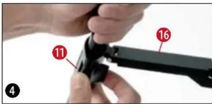
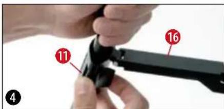
11 Locking clips (on tripod)
12 Mounting bracket for the tray (on division bar)
13 Tripod legs
14 Flexible shaft (long)
15 Flexible shaft (short)
16 Tripod leg brace
17 Latitude control rod
183 Eyepieces (0 31.7 mm or 11/4") f = 20mm,f = 12mm,f = 4mm
19 Zenith mirror
20 Inverting lens 1.5x
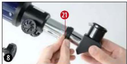
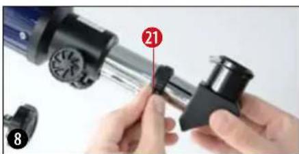
Parts of the Eyepiece holder (Figure 8)
21 Clamping screw
21a Lens Cover
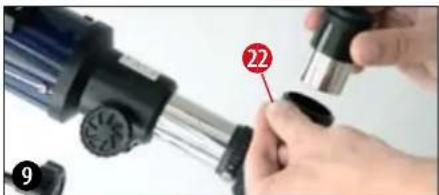
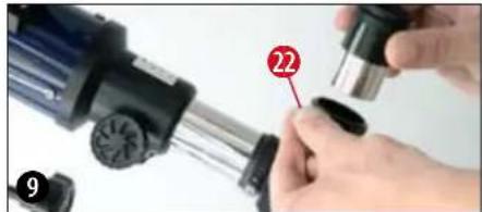
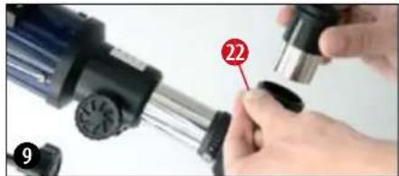
Parts of the Zenith Mirror (Figure 9)
22 Clamping screw
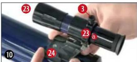
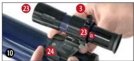
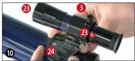
Parts of the Finder (Figure 10)
23 Front lens mount (objective lens)
23a Objective lens counter-ring
24 Finder holder
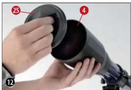
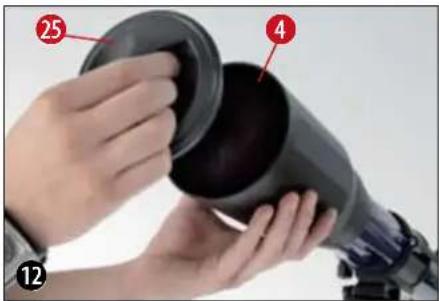
Parts of the Telescope Tube (Figure 12)
25 Lens Cover
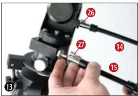
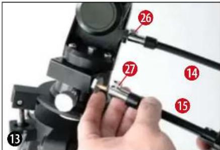
Axel with flexible shaft (Figure 13)
26,27 Clamping screw for the flexible shaft
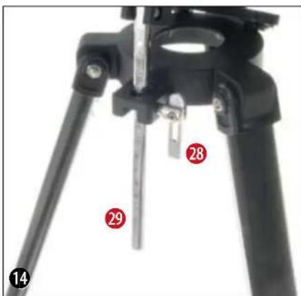
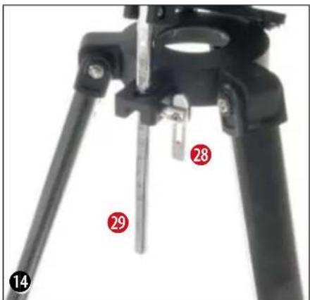
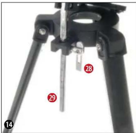
Pole elevator cradle (Figure 14)
28 Clamping screw for pole elevator cradle
29 Latitude control rod
30 Tilt plate
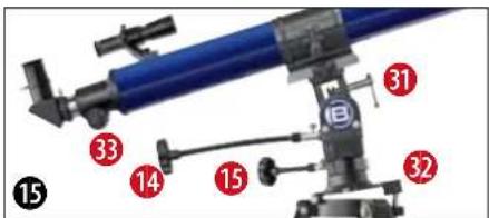
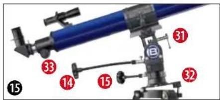
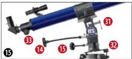
Parts of the Mount (Figure 15)
26 Flexible shaft (for counterweight shaft, for tracking)
27 Flexible shaft (for declination shaft)
31 Vertical clamp
31a Declination shaft
32 Dovetail adapter
33 Horizontal clamp
STEP1 - Assembly
2. General Information regarding Assembly, Positioning
Before beginning with the assembly, choose a suitable position for your telescope.
It will help if you assemble this apparatus at a spot from where you have a clear view of the sky, a sturdy surface beneath you, and enough space.
Important: Tighten screws only as much as you can by hand - do not "over-tighten" the screws.
3. Tripod
Take the three-legged tripod and set it vertically on the floor with the feet pointing downwards. Now take two of the tripod legs (13) and pull these legs carefully out away from each other, until they have reached their fully opened position. During this time, the entire weight of the

BREESER
m - 1 0 ;

tripod rests on one leg. Finally, set the tripod down on all legs, so that it stands straight.
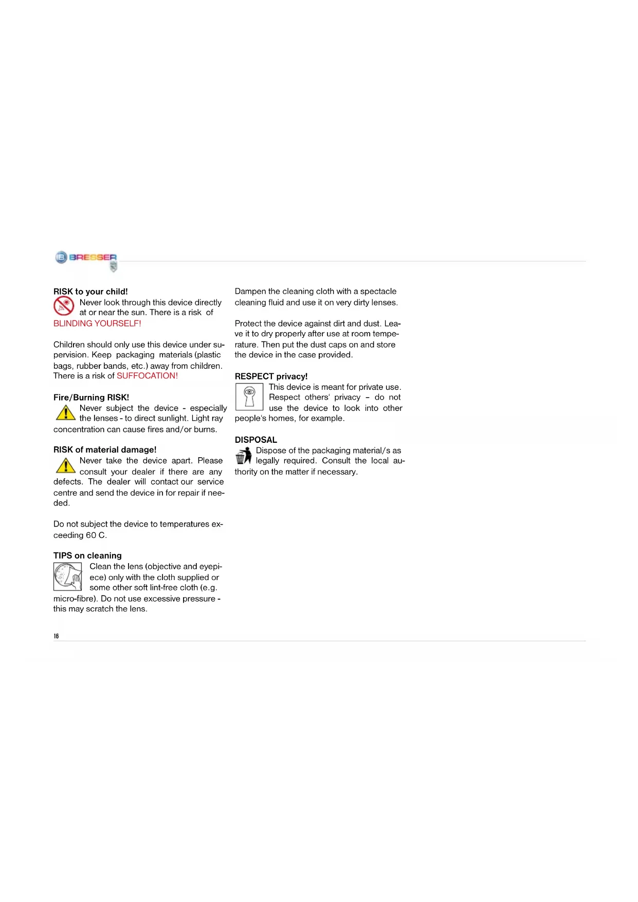
Loosen the three locking clips (11) (Figure 1 + 4) on the tripod legs, pull each individual tripod leg out until it has reached the desired length (see figure 4), close up the locking clips and set the tripod down on a sturdy, even surface.
TIP:
A small water level on the accessory tray can help you position your tripod horizontally.
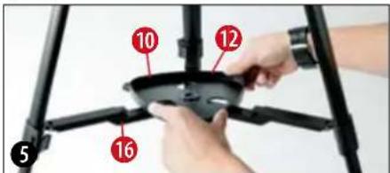
4. Mounting the tray:
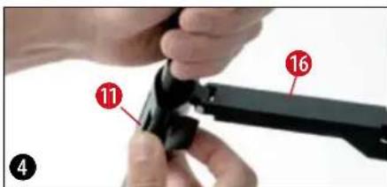
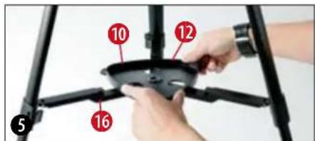
The accessory tray (10) (Figure 1 + 3) must be positioned with its flat side down in the middle of the tripod leg brace (16) (Figure 1), and then must be mounted by turning it 60^ in a clockwise direction (Figure 5).
The three projections on the tray plate must match up to the mounting brackets on the di
vision bars (12) (Figures 1 + 3) and must snap into place. If necessary, you may push the tripod leg brace downwards a little.
5. Tube
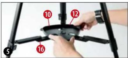
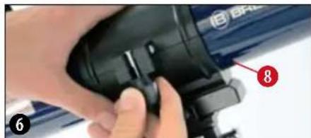
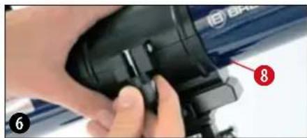
In order to mount the telescope tube (1) (Fig. 1), loosen the locking screw on the tube clamp (8) (Fig. 6) and open up the clamp.
Set the tube in the middle of the holder and snap the clamp shut again. Please screw the locking screw on the holder tightly, using your hand only.
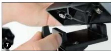
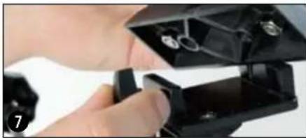
Now set the tube (and holder) onto the mount with the objective opening in the direction marked (N-marking on the tripod head, north point and telescope figure on the mount). Then fasten the tube holder with the clamping screw of the dovetail adapter on the mount head (Figure 7).
6. Inserting the Eyepiece
Three eyepieces (18) (Figure 2) and one zenith mirror (19) (Figure 2) come with your telescope. With the eyepieces, you can control the magnification of your telescope.
Before installing the eyepieces and the zenith mirror, take the lens cap (21a) out of the eyepiece holder (6) (Figure 1). Loosen the clamping screws (21) on the eyepiece holder and insert the zenith mirror. Then screw the clamp screws (21) back on.

BREESER
m - 1 0 ;

Finally, in the same way (by opening and closing the clamp screws) secure the 20-mm eyepiece in the zenith mirror.
Be sure that the entrance of the eyepiece (the end you look into) is facing straight upwards. This will make observation easier. Alternatively, loosen the clamp screws (21) on the eyepiece holder and turn the zenith mirror into this position.
7. Mounting and Adjusting the Finder
Slide the foot of the finder holder (24) completely into the finder holder base on the telescope tube (Figure 10). The finder holder will snap into place. Be sure that the objective lens on the finder is pointing in the direction of the front tube opening.
On the finder holder, there are adjusting screws for the finder (3) (Figure 1): two clamp screws (black) and one spring-loaded counter screw (silver). The clamp screws (black) are to be screwed (equally as far) in so that you can feel some resistance; the finderscope is then secure.
Before beginning an observation, it is absolutely necessary that you align the finderscope - the finderscope and the main telescope must point to exactly the same position. Here is the process for alignment:
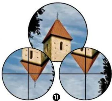
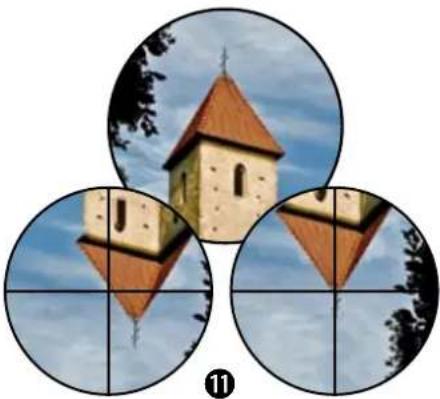
Take the 20-mm eyepiece, set it into the zenith mirror and aim the main telescope at an easy to find, clearly defined earthbound object (Figure 11, e.g. church steeple, gable of a house). The object should be at least 200-300 meters away. Hone in on the object so that it is exactly in the middle of the field of vision when you look through the eyepiece.

The image reproduced will be upright, but rotated around its vertical axis (you will see a mirror-image). In the finder, however, the reproduced image will be upright and its sides will not be reversed, as above. Now turn one of the two clamp screws (right/left) of the finderscope while looking continuously through the finder. Continue to turn until the finder's crosshairs are exactly over the position that corresponds to what you see when you look through the eyepiece of the main telescope.
Focusing the finderscope:
Turn the front lens mount (23) one to two rotations to the left. Now you can adjust the counter-ring (23a) by itself.

BREESER

m - 1 0 ;

( a - 5) ^2 > 0 ,
Look through the finder and focus on a faraway object. Tum the front lens mount (23) in one direction or another until the object appears in focus. Now screw the counter-ring (23a) in the direction of the lens mount.
8. Lens Covers
In order to protect the interior of your telescope from dust and dirt, the opening of the tube is protected by a lens cover. There is also a lens cover (21) on the eyepiece holder (6) (Figure 1).
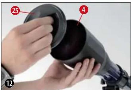
For observing, take the caps off the openings.
9. Flexible shafts
In order to facilitate the exact fine adjustment of the declination- and right ascension shafts, the flexible shafts have been placed on the holders of both these shafts, in the places designed for that purpose.
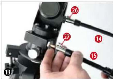
The long flexible shaft (14) (Figure 1) is mounted parallel to the telescope tube. It is secured with a clamp screw (16, 17) on the designated indentation on the shaft.
The short flexible shaft (15) (Figure 1) is mounted sideways. It is secured with a clamp screw (16, 17) on the designated indentation on the shaft. Your telescope is now ready for use.
STEP II - Using the Telescope
1. Operation -Mounting
Your telescope comes with a mount that gives you two possibilities for observation.
A: Azimuthal = ideal for viewing objects on the Earth (terrestrial observation)
B: Parallax = ideal for viewing objects in the sky (astronomical observation)
Regarding A:
In azimuthal mode, the telescope swings horizontally and vertically.

Loosen the pole elevator clamp screw (28) and lower the tilt plate (30) until it is horizontal (in other words, until it stops). Screw the pole elevator clamp screw back on.
Loosen the vertical clamp (31) and set the tube in a horizontal position. Screw the clamp back on.
By turning both flexible shafts (14, 15) (Figure 1), the telescope can be moved horizontally and vertically.
Regarding B: Kapitel (3-11).
2. Set-Up (at night)
A dark location is very important for many observations, as bothersome lights (lamps, lanterns) can have quite a negative effect on the detail and clarity of the telescope image.
If you leave a bright room at night to go outside, your eyes need time to adjust to the darkness. After approx. 20 minutes, you can begin with
the astronomical observation.
Do not observe from closed spaces, and set up your telescope with the accessories approx. 30 minutes before beginning observation; this will ensure that the temperatures inside the tube have adjusted.
In addition, you should be careful to set your telescope on a level, stable surface.
3. First time Set-up
Loosen the pole elevator clamp screw (28) and set the tilt plate (32) roughly to the latitude of your location, according to the scale of the latitude control rod (29) - in Germany, this is about 50^ . Point the part of the tripod with the North-marking (N) in a northerly direction. The upper side of the tilt plate will also be pointing north. The latitude control rod will be pointing south.
4. Positioning of Geographical Latitude
From a street map, an atlas, or the Internet, find out your location's angle of latitude. Germany lies between 54^ (Flensburg) and 48^ (Munich) north geographical latitude. Now loosen the pole elevator clamp screw (28) and tilt the tilt plate (32) until the number on the latitude control rod (29) that is next to the
clamp is the same number as your location's angle of latitude (e.g. 51^ ).
TIP:
The angle of latitude can always be found in an atlas on the right side, or on the left side of a map. You can get more information at your city hall, your land registry office, or on the Internet: for instance, at www.heavens-above.com. There, under "Anonymous user > Select," you can choose your country; the relevant information will then come up.
5. Final orientation
Turn the declination shaft (8) as well as the telescope holder upwards 90^ (white arrow markings at the front of the mount will be across from each other). Set the tube the right way around (see telescope illustration and north arrow) in the holder and tighten the clamp screw. The eyepiece of the telescope is now pointing at the ground; the objective lens is pointing at the North Star. Loosen first the clamp of the latitude control rod and then the clamp of the declination shaft, and bring the North Star into the middle of the eyepiece field of vision.
Finally, retighten the clamp. From this point onward, the tripod may not be moved or adjusted because the orientation will be lost.


The telescope is now properly oriented. This procedure is necessary for tracking celestial bodies.
6. Tracking- and/or Observation Position
Loosen the vertical clamp (8) and tilt the telescope tube 90^ downwards. Loosen the horizontal clamp (33) and turn the telescope 180^ to the right or left, until the objective lens is pointing in the direction of the sky.
Retighten all clamps so that you can track with the flexible shaft.
The manual operation of the counterweight axis (right ascension axis, R.A. axis) via the flexible shaft (26) allows for the rotation of the Earth in such a way that the positioned object always stays in the eyepiece field of vision.
If you would like to switch to another object, loosen the clamps, swing with the tube in the proposed direction and retighten the clamps. The fine adjustment is then performed with the flexible shafts (14, 15) (Figures 1).
7. Finder
Your telescope is now roughly aligned and set up.
In order to obtain a comfortable observation position, carefully loosen the screw on the tube clamp (8) (Figure 1) so that you can turn the telescope tube. Bring the eyepiece and the finderscope into a position from which you can observe comfortably.
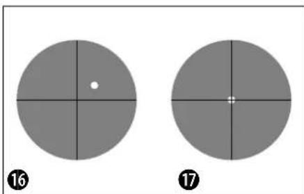
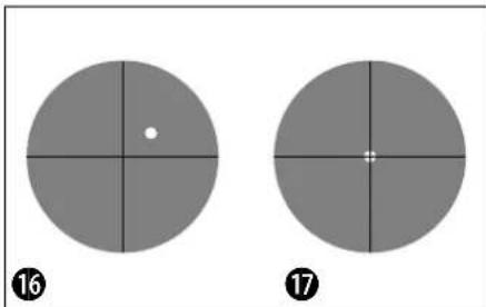
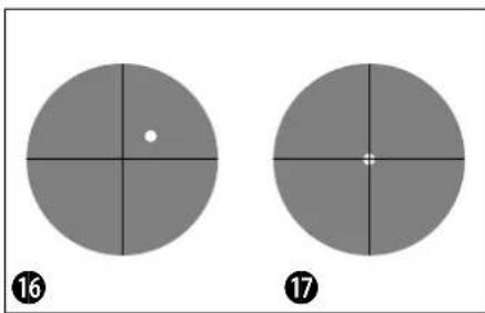
The fine adjustment happens with the help of the finderscope (2). Look through the finder and try to hone in on, for instance, the North Star (Figure 16), positioning it in the middle of the finder's crosshairs (Figure 17). For the exact adjustment, the shaft of the counterweight axis (26) as well as the shaft of the declination axis (27) will be helpful.
8. Observation
After you have located the North Star in the finder, you will be able to recognize the North Star when you look through the eyepiece of the telescope. If needed, you can angle the telescope even more exactly toward the star (with the help of the flexible shafts), or you can adjust the focus with the focus knob (7) (Figure 1).
Additionally, you can now switch to a higher magnification by changing the eyepiece (to a smaller focal width). Please be aware that the magnification of the stars is barely perceptible.
TIP:
Eyepieces are lens systems designed for your eye. In an eyepiece, the clear image that is generated in the focal point of a lens is captured (in other words, made visible) and magnified still more. Eyepieces with various focal widths are necessary in order to achieve various degrees of magnification. Begin each observation with an eyepiece with a low magnification (= large focal width, e.g. 20 mm).

9. Finding stars
In the beginning, you will certainly find it difficult to orient yourself in the sky, since stars and constellations are always moving, and their position in the sky varies according to the season, date, and time.
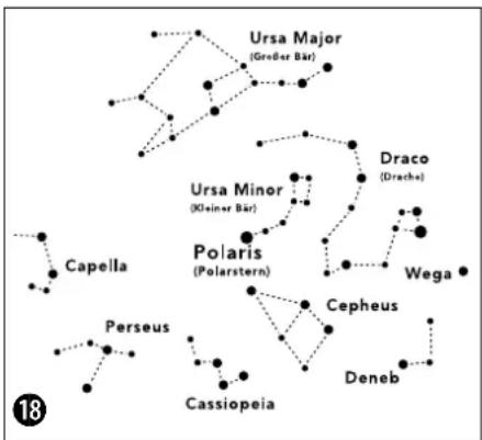
The North Star is an exception to this. If you were to imagine the polar axis of the Earth extending out into space, it would approximately hit the North Star. The so-called north celestial pole is the starting point for all star charts.
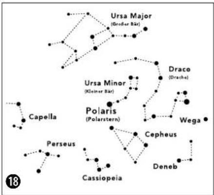
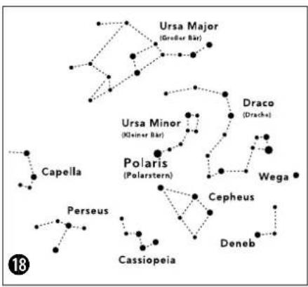
On the drawing (Figure 18), you see a number of the more familiar constellations and star clusters, which are visible throughout the year. The position of the stars is, of course, dependent on date and time.
If you have fixed your telescope on one of these stars, you will notice that within a short time it disappears from the eyepiece field of vision. In order to compensate for this effect, operate the flexible shaft (17) of the counterweight axis, und your telescope will follow the apparent path of this star.
10. Accessories
Three eyepieces (18) (Figure 2) come with your telescope. By switching the eyepieces, you can control the magnification of your telescope.
The zenith Mirror (19) (Figure 2) produces an image reversal (mirror-image) and is only used for astronomical observation.
In order to see an image that is upright and properly orientated side-to-side (no mirror-image, in other words), you must use the inverting lens that came with your telescope. Loosen the clamping screw (39) and take the zenith mirror out of the eyepiece holder (6) (Figure 1). Then set the inverting lens (20) (Figure 2) straight into the eyepiece holder and retighten the clamping screws with your hand. Then, place the eyepiece (e.g. f = 20 ~mm ) into the opening of the inverting lens and tighten the clamping screw there.
Note:
| Focal width of the telescope tube : Focal width of the eyepiece = Magnification |
| Let's calculate: 900 mm : 20 mm = 45x900 mm : 12 mm = 75x900 mm : 4 mm = 225x |

BRESSER
图
11. Dismantling the Telescope
Hopefully your observation session will have been interesting and successful; afterwards, it is recommended to store the telescope in a dry and well-ventilated room. Please do not forget to place the lens caps back onto the front tube opening and the eyepiece holder. All eyepieces and optical accessories should also be stored in their respective containers.
TIP:
The inverting lens is not suitable for astronomical observation. Here, work with just the zenith mirror and an eyepiece. For terrestrial observations and for viewing nature, you may use the inverting lens with an eyepiece.
Troubleshooting:
| Problem Solution | |
| No image Remove lens cap from lens opening | |
| Fuzzy image Adjust focus with focus adjustment knob | |
| Focusing is not possible | Wait for temperatures inside tube to balance out (about 30 minutes) |
| Bad image Never observe through a pane of glass. | |
| Object of observation is visible in finder, but not in telescope | Align finder (see chapter 7) |
| Sluggish or stiff steering of the shafts Balance | telescope |
| Image is "askew," even with zenith mirror | The eyepiece holder in the zenith mirror must be aligned vertically |

1. Technical data:
- Double-lens system (achromatic) made of glass
- Alt-azimuth mount with equatorial wedge (Optimised mounting system with flexible shafts)
Magnification: 45x - 337.5x - Lens Diameter: 70 mm
Focal Length: 900 mm
3 eyepieces: K-20 / K-12 / K-4 mm - Diagonal Mirror
- 6x25 Viewfinder
1.5xErecting lens - Adjustable Aluminium Tripod
2. Possible objects for observation:
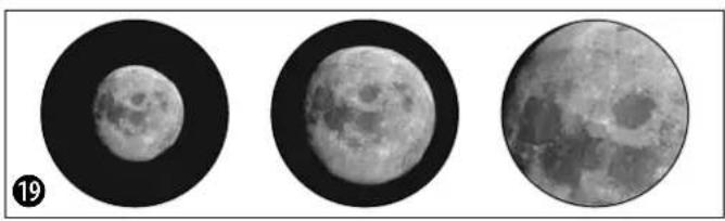
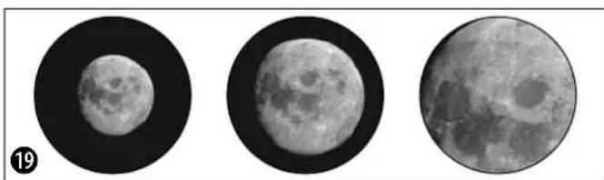
We have compiled and explained a number of very interesting celestial bodies and star clusters for you. On the accompanying images at the end of the instruction manual, you can see how objects will appear in good viewing conditions through your telescope using the eyepieces that came with it.
The Moon
The moon is the Earth's only natural satellite.
Figure 19)
Diameter: 3.476 km
Distance: approx. 384 401 km
The moon has been known to humans since prehistoric times. It is the second brightest object in the sky (after the sun). Because the moon circles the Earth once per month, the angle between the Earth, the moon and the sun is constantly changing; one sees this change in the phases of the moon. The time between two consecutive new moon phases is about 29.5 days (709 hours).
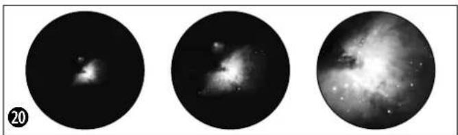
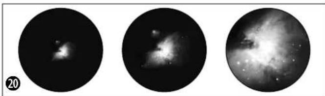
Orion Nebula (M 42)
M 42 in the Orion constellation (Figure 20) Right ascension: 05:32.9 (Hours: Minutes) Declination: -05:25 (Degrees: Minutes) Distance: 1.500 light years
With a distance of about 1500 light years, the Orion Nebula (Messier 42, abbreviation: M 42) is the brightest diffuse nebula in the sky - visible with the naked eye, and a rewarding object for telescopes in all sizes, from the smallest field glass to the largest earthbound observatories and the Hubble Space Telescope.
When talking about Orion, we're actually referring to the main part of a much larger cloud of hydrogen gas and dust, which spreads out with over 10 degrees over the half of the Orion constellation. The expanse of this enormous cloud stretches several hundred light years.
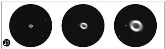
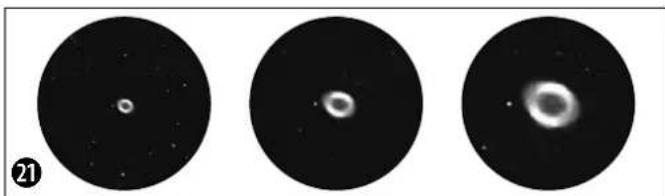
Ring Nebula in Lyra constellation (M 57)
M 57 in the Lyra constellation (Figure 21) Right ascension: 18:51.7 (Hours: Minutes) Declination: +32:58 (Degrees: Minutes) Distance: 2.000 light years
The famous Ring Nebula M 57 in the constellation of Lyra is often viewed as the prototype of a planetary nebula; it is one of the magnificent features of the Northern Hemisphere's summer sky. Recent studies have shown that it is probably comprised of a ring (torus) of brightly shining material that surrounds the central star (only visible with larger telescopes), and not of a gas structure in the form of a sphere or an ellipsis. If you were to look at

BRESSER


the Ring Nebula from the side, it would look like the Dumbbell Nebula (M27). With this object, we're looking directly at the pole of the nebula.
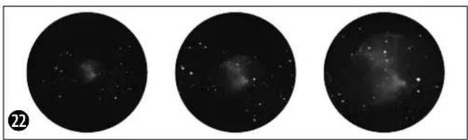
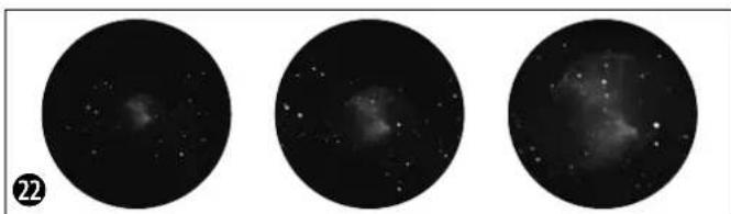
Dumbbell Nebula in the Vulpecula (Fox) constellation (M 27)
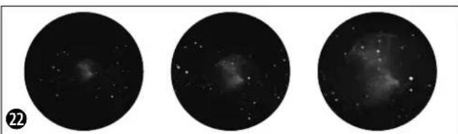
M 27 in the Fox constellation (Figure 22)
Right ascension: 19:59.6 (Hours: Minutes)
Declination: +22:43 (Angle: Minutes)
Distance: 1.250 light years
The Dumbbell Nebula (M 27) in Fox was the first planetary nebula ever discovered. On July 12, 1764, Charles Messier discovered this new and fascinating class of objects. We see this object almost directly from its equatorial plane. If you could see the Dumbbell Nebula from one of the poles, it would probably reveal the shape of a ring, and we would see something very similar to what we know from the Ring Nebula (M 57). In reasonably good weather, we can see this object well even with small magnifications.
The Moon
Orion Nebula (M 42)
Ring Nebula in Lyra constellation (M 57)
Dumbbell Nebula in the Vulpecula (Fox) constellation (M 27)
f=20 mm f=12 mm f=4 mm

3. Telescope ABC's
What do the following terms mean?
Barlow Lens:
The Barlow Lens was named after its inventor, Peter Barlow, a British mathematician and physicist who lived from 1776-1862. The lens can be used to increase the focal width of a telescope. Depending on the type of lens, it is possible to double or even to triple the focal width. As a result, the magnification can of course also be increased. See also "Eye-piece."
Focal width:
Everything that magnifies an object via an optic (lens) has a certain focal width. The focal width is the length of the path the light travels from the surface of the lens to its focal point. The focal point is also referred to as the focus. In focus, the image is clear. In the case of a telescope, the focal widths of the telescope tube and the eyepieces are combined:
Lens:
The lens turns the light which falls on it around in such a way so that the light gives a clear image in the focal point after it has traveled a certain distance (focal width).
Eyepiece:
An eyepiece is a system made for your eye and comprised of one or more lenses. In an eyepiece, the clear image that is generated in the focal point of a lens is captured and magnified still more.
There is a simple formula for calculating the magnification:
Focal width of the telescope tube / Focal width of the eyepiece = Magnification
You see: In a telescope, the magnification depends on both the focal width of the telescope tube and the focal width of the eyepiece.
From this formula, we see that if you use an eyepiece with a focal width of 20 mm and a telescope tube with a focal width of 600 mm, you will get the following magnification: 600mm / 20mm = 30 times magnification
Inverting lens:
The inverting lens is set into the eyepiece holder of the telescope before the eyepiece itself. This lens can produce an additional magnification (mostly around 1.5x ) via the integrated lens in the eyepiece. As the name suggests, the image will be turned around if you use an inverting lens, and appears upright and even properly oriented on the vertical axis.
Magnification:
The magnification corresponds to the difference between observation with the naked eye and observation through a magnification apparatus (e.g. a telescope). In this scheme, observation with the eye is considered "single", or 1x magnification. Accordingly, if a telescope has a magnification of 30x, then an object viewed through the telescope will appear 30 times larger than it would with the naked eye. See also "Eyepiece."
Zenith mirror:
A mirror that deflects the ray of light 90 degrees. With a horizontal telescope tube, this device deflects the light upwards so that you can comfortably observe by looking downwards into the eyepiece. The image in a zenith mirror appears upright, but rotated around its vertical axis (what is left appears right and vice versa).

Distance:env.384,401 km
m = 311 ;
m = 311 ;
11. Demontage van de telescoop
Distance: circa 384.401 km
m = 311 ;


ONACHOCT OT HmUeCTBeHa nobpeda!
He pa3rno6BaBte yctpoCTbTO. B cnya, Ye Bz3HnKHe HnKaKbB DeΦeKT, MoJn CBpKHe Tce C HaSiN TBPROBcN PpeCTaBHTen. ToI ce Ce CbPKe Cbc cepBn3Hn Hn cHTbp N ne Hn ppaTHy cTPOCTBOTo 3a nonpaBka, aKO e Heo6xOdmo.
He n3naIte yctpoNCTBOTO Ha TemnepaTpaHd 60^
3AEBEKK3a nouchTaBaHeto

IouncBaTe neuTe (Bn3bOpn n/ nnneun) C meKa Kbpna, KOrTo He OCTaBA BnAkhna NmMbx (HanpImep
MnKpOΦn6bP).HeHaTnCKaTe CnHc H nata 3a Da He HaDpackateJeuNTe.
3a da otctpaHnTe no-ynopHTne 3aMbpcBaHHa, HablaXhHeTne NOUcTBaUcaTa KbPna Cpa3TbOp 3a NoOuCtBaHe Ha OUYa N TbPkAte HeKHO Ieunite C HeJ.
IpeNa3BaIte ycToBTOOT npax nBnra! CneI yNtpe6a -ocOeHO BycnoBna HaBncoKa BnAKnOCT -octaBeTe yCToBTODa ceakImMaTHn3npa 3a H3BecTHo Bpeme,3a Da MoKe ocTaTbHATA Bnara Da ce N3napiOTcpanHe TOKpHbAnoto 3a npax nPnp6epete ypeDa YcaHTata OT KOMnEKA.
3aunHa JnHHTo npoctpaHCTBO!

BnHoknIte ca npedHa3HaueHcama 3a nUHO noJ3BaHe. Mony yBaKaBaBae npaBOTo Ha yeDInHeHne Ha
IpyrXopa-Hn3no3BaIte6HOKnTe 3a da rIeDATE B yKAn anapTaMeHTn HAnpMep.
H3XBbPnAHE
H3XbPnIe pa3dEnHO onaKOBbHITe MaTePnAnCnopeBnA Hm (xapTn, KapToH n dp.). CbPkTe ce c MecThata cnJyK6a 3a pa3dEnHO cmetocb6npaHe nn HHCTaHnHTa 3a ONa3BaHe Ha OKoIHATA cpe Da 3a INHOpMaUNr OTHOCHO npabINHOTo HxBpnaHe.

Toba ca yactnte Ha Teleckona (H3o6p.1-3)
1 Ty6yc Ha Teneckona
2 Tbpcay
3 BInrBoBe 3a peryInpaHe Ha Tbpcaa.
4 O TBOP Ha Ty6yca
5 O6eKTHB
6 OkynpEn Bb3eN
7 BnHT 3a HacTpoKa Ha foKyca
8ДьржанHaубуca
9IbabaHa CtaTnBa (C HAcTpOka Ha nonpHata BnCOUHa NMOHTPOBKA)
10 TdeneHne 3a npHaJnEJxHocTn
11 Cko6n 3a npikpenBaHe (KbM cTaTHBa)
12 CkO6n (Ha cToiKaTa) 3a OTeJeHHeTO 3a npHaadJeXHOCTN
13 TpHnHor
14 TbBkAB JIOCT (aBnB)
15TbBkABNoCT(Kbc)
16 Pa3wnpnten Ha TpHora
17 Hactpoika Ha rpaayca Ha pa3upeHneTo
183 Okynpa (31,7 MM Cb0TB. 11/4"):
f=20MM,f=12MM,f=4MM
193eHnTHo orIeIaIoo
20 PeΦpaKTop 1,5x
HaIbPkaHHe HaokyIpa (N3o6p.8) ETANI-Crno6Bahe
21 3aTaraBnHT
21a Ppepa3Ho Kaane
Ha 3eHHToTo orIeJaNo (H3o6p.9)
22 3aTaraBnHT
YactnHaTbpcaya(H3o6p.10)
23 PpeHa CnCTema OIeun (O6ekTnB)
23a KoHTpaWai6a Ha 06eKTHBa
24 丁bpkaHa TaBpcaya
Yactn Ha Ty6yca (N3o6p.12)
25 PpeNa3Ho Kaanae
Oc C TbBkAB JIOCT (H3o6p.13)
26,27 3aTarau BnHT Ha bKaBna JIOCT
Poiipha oc (V3o6p.14)
28 3aTgauBHTHaIpaHataoc
29Пьбгчзнстpoикha reorpaФСКATAшрпHA
30 BnKeea ce natafOpMa
HaMOHTNPOBkata (H3o6p.15)
26 TbBkab NoCT (3a npocneIbaHe no yacobata oc)
27 TbBKBAB NOCT (3a DeKJIHaHauHOHata OC)
31BepTKaJIHn KneMn
31a DeklnHaauNoHnOc
32 AanTOp Tn,naCTOBnu OanaKa
33 Xopn3OHTaJIH KIeMn
2.06uHaHΦopMaun3a crno6raHeTo, H36Op HA MACTO
Ipei Da 3aOnuHew CbC CrNo6BaHaTe Tp6Ba Da H36eew NoXoJauO MRCTo 3a TB0B Teneckon.
LHe 6bIe NoJIe3HO da N36peu MMCTO,OT KOETo Ie HMaU Do6pa BUNMOCT KbM He6eTO,CTaBnHa OCHOBA NIOCTaTbYHO pOcTpaHCTBO.
BaHHO: 3aTeHHIO6pe BCNUBHTOBe Ha pKa 3a da npedOTbpaTHN ppeBbptaHETo HM.
3. CTAHB
B3emn TpknpaKna CtaTnB n ro noCTaBn XOpH 30HTaHNO C kpaKaT a HADOny.Cera xBaHn Dba OT KpaKaT a (13) n r naTbOpn BHMaTeHn Ha MaKcMaHIO pa3ctoHHne eHN O npTo3n HAHH cHaIATA TeXeCT Ha cTaTHBa nada Bbpxy eINHH KpaK. HApAa NoCTaBn CtaTnBa H3npaBeH.

BFRSER

Ocboodn trnte 3aTraun ck6b (11) (H3o6p. 1 +4) Ha KpaKaTaHa cTaNbA, pa3TeRn BCEkn KpaDIO XeNaHa TaBnHa (BnK N3o6p.4), 3aTeHN OTHOBCKoBHe n CLOKn CTaNbHa HapabHa OCHOBA.
CbBET:
B OTDENHnEto 3a npHaNDeKHOHMa Ma JbK HbEnIp, KOITMOKHe Da TNIOMORHe pN XOpI3OHTaJIHOTo N03NUOHHPaHE Ha TBOr CTaTHB.
4. MoThnpaHc Ha OToJeHeHcTe 3a npHaDneKHOCTN
OTdeneHHeTo 3a npHaIeJHKoHcTn (10) (N3o-6p.1+3) ce noCTaBc nNoCKata cTpaHa HaDony no cpeDataHa pa3WuPteNa Ha TpHora (16) (N3o6p.1) n Ce MoHTnpa KaTO CE BbPTn no NocKa Ha YacOBHKnOBaTa CTrpenka (N3o-6p.5).
Tpne Kpa Hnntopmata Ha oteneHneto Tp6ba da cbbnadat cbc ckObnte (12) (N3o6p. 1 + 3) Ha cpeHNthe OCN n da Bn3at B THX. 3a
cTMa MoKe pa3WnHpTeNr Ha TpHOra neKo Da ce HATNCHe HADony.
5. Ty6yc
3aMOHTaHa HTy6yca(1)(H3o6p.1)pa3xna- 6n 3aTARaUNBnHT Ha CkO6ata Ha Tsy6yca (8) (H3o6p.6) n OTBOPn CkO6ata.
IocTaN Ty6yCa B cpeaTa Ha IbPkaHa 3aTBOpN OTHOBO CkObata. 3aterHn BnHTa HapbKa.
Cera noctabn tybcya,3aedno cIbpxkaa Byka3aHata nocoka (N-O3haueHHe Ha rnaBata HA ctaTnBa, CTpeIka- ceBep H3O6paKeHHe Ha Teneckona Ha MOHTnpOBkata) Ha MOHTpOBkata. Cera 3akpeni Dpbkaua Ha Tybca Cbc 3atraunn BINT Ha aanTopa TnN ,NaCTOBnua OnaWka" KbM IbaBata Ha MOHTnpOBkata (N3o6p.7).

6. NocTabrHe Ha OKyIpa
TBOAT TENECKON NDBA B KOMNNEKT C TPN OKYJIAPA (18) (N3o6p.2) n eHNO 3eHNTHO ORIeJaLo (19) (N3o6p.2).C OKYJIAPTE ONpeDenHJXeJIHOTO YBENHHe Hn TBOR TEICKON.
Ipei Da noctabuW OKyIaPHTe N 3EHINTHO OrIeJalO TpRbA Da OTcPaHNI PpeJNa3HOTOKanaue(21a) ot OKyIaPnH B3en (6)(N3o6p. 1). PaXna6n 3aTgauNTe BuHTOBe (21) Ha OKyIaPnH B3en N Bkapai IbpBO 3EHINTOOrIeJalO.CneD ToBa OTHOB 3aTeHN BuHTOBete (21).


BRESSER

CneTobnno Cbunna HauHn COTBnHTBaHe n 3aBnHTBaHe Ha 3aTaraunte BnHTOBe (22) 3akpenBaW Okynpa ot 20 MM B 3eHNTHOTO Orndano.
O6bPHN BnHMaHHe Ha TOBa, MRCTO 3a rIe-daH He OKyIpa Da 6bDe BePTnKaIIHO Harope. TOba yneChraB rIeHaTe. B npOTuBEH cnuyai pa3xIa6n BnHTa (21) Ha OKyIrpHnBb3en I 3aBbPTn 3EHTHOTo ORIeDaIIO B Ta3n IO3nIur.
7. Tbpcau-MOHTaH HacouBaHe
ByTHn naneuHa IbpkayHa Tbpcaa (24) DOKpaB B OCHOBATA My HA Ty6yca Ha TEnecko- na (N3o6p.10).IbpkaHT Ha Tbpcaa BnHa ce 3akpenBa.BHmabai npn noCTaBHHeTo 0eKTHBt Ha Tbpcaa Da e B Nocoka, coeua npedHn OTbOp Ha ty6yca.
HaIbPkaaHa Tbpcaa CeHAMpat BnHtO Bete 3a perynipahe Ha Tbpcaca (3)(N3o6p. 1):Dba 3atraaun BNHTa (cepH) n edha npyKHHa KOHTpaawba (cpepbcta).3atraaHTe BnHTOBe (cepH) Tp6Ba da ce 3aterHat paBHomepno DToONKOBA, ye da ce yceua cbnpotNBHeH; TaKa TbpcaybTe 3akpehen.Ipein da 3anoHew c HabIOdeHEnTo e 3aTbHKNTENHO Da Harnacu Tbpcaa-3a CENTa TbpcaybTn INaBHNAT TeNECKON Tp6Ba da ca pueuHn Hacooyen B Edna Ncbua No3uHa. 3a HacouBaHeto IM Tp6Ba da HappaBNI CneHOTO:
Bzemn Okynpa ot 20 MM, noCTabn ro B 3eHHTHO TO OrNeJaIO HAcOu IaABHn TeneckON BbM Iecen 3a HAMpaHe, ENo3HaNo DeHINHPaH ZEmeH O6K (N3o6p.11, HanPmep Kynon Ha CbPKBa, NOKPNBeH BpX Ha Kbua). Pa3cToHHnE To P8bBa Da 6bJe Nohe 200-300 M. Harlacn Teneckona Taka, Ye o6eKbT da nonaHHe ToUHO B CpeDaTa Ha 3pntEnHOTOnne Ha OKynpa.
N36paJKeHHeTo e 3npaBeHo, Ho cTpaHnHo orNeJaHHO o6bPhato. B TbpcaHa o6aue e n3- npaBeHo i cTpaHnHo BApHo. Cera 3anoHn Da bTpHn (HaHcHo/HaHBo) eoHn OT dBaTa 3aHrau BNHTa Ha TbpcaKaTO eHNOBpEmeHNO rMaau ppe3 Hero. PpaBn TOBA DOKATO KpbCTbT Ha TbpcaA DOCTIRHe ToHATA N03uN, KOrTO Da CbBnada C N03uNtA Ha OKyIpa Ha rnaBHnTeleckon.
Hactpoika Ha foKyca Ha Tbpcaya: 3aBbptn npedhata cncTeMa ot leu (23)do DBe 3aBbptaan HanaBO.Cera MoKeu DaHaCTponu OTdeJIHO KOHTpaaw6aTa (23a).

BRESER
1

IorneHn npes Tbpcaa n Fokycnpa daeH otdaeneH o6ekt. 3abptn npedhata cncteMa ot neun (23) B ehdata n B dpyrata nocoka, dOKato o6ekTbT ce BNn rCHO. Cera 3aterHn KOHTpaawbaata (23a) no nocoka h cnctemaTa OT neun.
8.Ппeдзн Качета
3a da ce npednataR BbtpeunHte cactn Ha TBOI TELECKON OT npax M pbcOTnHa OTbopa HA Ty6yca NMa npedna3Ho Kanaue (25).Cbio Taka npedna3HO Kanaue (21) NMa n Ha OKyJIAPHNB3eN (6)(N3o6p.1).
3a Ha6JIODeHHe MAXHN KanaYeTata OT OTOBOpHTe.
9. TbBKBaB NoCTOBe
3a da ce ynechni npeun3nata Hactpoika Ha octa no DeKlnHaunn H peKTacuen Tpr6Ba da ce 3aKepeNRT BbKaBNTe loCTOBe Ha npEd-Ha3HaueHNTe 3a cenTa DbpXauH Na dBete OCN.
Дьгггтьвкавлoct(14)(ИЗбp.1)ce MoTHnIpa napaJIeHNo Ha Ty6yca.3akpenBaHTo CTaba C BnHT(16,17)KbM npedBnDEHnHaDpe3 HaOCTa.
KbCnT TbBkAB JocT (15) (M3o6p.1) ce MoTHa CtpaHnHc. 3aKpenBaHeTo CTaba C BHT (16, 17) KbM npedBnHeHH Hape3 Ha octa. Cera Beue TBoRr Teleckon e rotob 3a paOba.
ETAN II - I3noJ3BaHe Ha TeJeckona
1.YnpaBneHHe-MOHTpOBKa
TBOI TENECKON pa3nOJaRA C MOHTNPOBka, KO-ATO N03BOJRA JBa HauHa Ha H6NIOHeH.
A:A3myTaanHO = ndeanHO 3a 3emHO ha6nIO-ene (TepeCtnpAnHO Ha6nIOeHne)B: EKb-TopnHNO = ndeanHO 3a He6ecHO ha6nIOeHne (actpoHa6nIOeHne)
KbMa:
Pn a3MyTaJHaT a NoCTaHObKa TeNEcKoNTbT
ce DnKn BepTNKaJIHo n XOpN3OHTaJIHO.

Pa3xna63aTgauin BnHT 3a HactpoKaTa Ha nonpaHata OC (28) nHaKIOHN DnBKeUata Ce nlatopma DoKATO 3actaHe XOpN3OHTaHO (do Kpa). 3aTeHn OTHOBo BNHTA.
Ocbo6oBn BepTnKaHInTe KIeMn (31) nocTaBn Tybyca B xopnsOHTanHO nIoJxHeHne. 3aterH N OTHOBKlEMNTE.
TeneckonbT cera moke kato ce Bbptat DbaTa noDBNHNIOCTa (14, 15) (N3o6p.1) da ce DBNHN XOpIN3OHTaJIHO INBPTKAnHO.
KbM B: bNk pa3den (3-11).
Ta NOCOKa H3aTeRnO OTHOBCKoBte.ΦHnHaTahacToPouKa ce NoCTHra OTHOBc FbBkABTeNoCTObe (14,15)(N3o6p.1).
7. Tbpcau
Cera TBoRr Teneckon e noLyuHn OCHOBHnTe HAcOKa N HAcTPOkN.
3a da noctnHHeu yOo6Ha no3nua 3a Ha6IIODeHHe pa3XnaBnHMaTeHbNHTa Ha bPJaHauHa ty6yca (8) (V3o6p.1), 3a da moKeeW Da BbPTnW camn rTy6c.Harlnacn Okynpa n Tbpcaa B no3nua,OT KOrTo da Tne yOoHo Da H6IIOdaBaaw.
Hnata HactpoKa CTaBc NOMOHTa Ha Tbpcaya (2).IorneHN npe3 Tbpcaua n ce onTai HanpImep Da HarnacuN nonpHaTa 3Be3da (N3o6p.16) B cpeata Ha Kpbcta(N3o6p.17).3a npenuHa HactpoKa ue ca ot NOMOIOCTOBete Ha Yacobata oc (26) Na DeeklnHa-ooHHata oc (27).
8. Na6HNO3eHne
Cne KaTo cn HactpOnn noJrphata 3Be3a B Tbpcau,ue MoKeew Kato nOrIeHHeu npes Okynpa da Ra pa3no3Haeeu npe3 Teneckona.
B cnyuacn omoaTa Ha TbBkabte NoCTOBe 电MOxew Da HACOHN TEeCKOna C no-ToJrMa TOHOCnPMA 3BE3data KaKTo n da npednpemew HAcTpoKa Ha KOKyca (7) (N3-06p.1) 3a NO-rolma JCHota Ha KapTHHaTa.
OcbenToba cera MoKeW Upe3 CmHa Ha OkyIpa (c TaKbB C NO-MaIKO FOkyCHO pa3CTOHHne) da NoCTnHHeu No-ToJAMo YBeJIuHHeHne.
MOna 06bpHn BnHmHaHe Ha TOBa,Ye yBeneHHeHTo Ha 3Be3dTe e HnIOxHO 3a QOBeKoTO OKO.
CbbET:
Okynapte ca 06bphatn KbM OKOTcHTEMn OT leu. C okylapa ce B3npema KaptnHaTa, KOHO B3HNKBA BB FOKyca Ha O6kTNBa, T.e CTaba BNIMa n Ce yBEniYaBa Oue BeHbX. Heo6xOIMn Ca OKyprn c pa3NHy FOkychn pa3CTOHHN 3a da Ce nonyat pa3NCHyBEInHHe. 3anoBuB BCaKO Ha

BRESER
m - 1 0 ;

6nIOeHne cOKyIaP C B3MOxHO HAI-MaKo yBEnueHne(= rOJMAO FOkycho pa3cToHHne, HApnMep 20 MM).
9. TbpcHe Ha 3Be3n
B haHAnOTo opHeHTnpaHTo B 3Be3dHTo He6e cnHypHo ue Tc Ce CTpyBa tyDHO, 3auOTo 3Be3dHte N Cb3Be3dNtA Ca NoCToRHHo B DnKHeHne I PpOMeHr CBOrA No3uHa He6eTo cNopeI ce30Ha, DaTata N Yaca.
EINHCTBeHOTOn 3KKnIOUeHHe e NIOIrpHaTa 3Bc3Ja. Ppe3 HeN IpemHHaba (OcTa TcHo) MNCIEHOTo IPODbJIKeHHe Ha NIOIrpHaTc OC Ha 3eMra.Taka HapeueHnT He6ecen
ceBepen NIOUCnyK3aH3XoHaTOyKaHa BCNUK 3Be3HN KAPTN.
Ha n3o6paqhenHTo (N3o6p.18) MoKeew da BnDnH HkON PO3HATn Cb3Be3Dn H 3Be3Dn, KOHTO CE BnKdT ppe3 cIyNaTa rOINHa. NOppeBata Ha Cb3Be3DnTa oBaue 3aBnCn OT DaTATA uYaca.
Ako HacouH TeneckOa CN KbM HAKo OT Te3n 3Be3n CnE N3BecTHO Bpeme Ue yCTaHOBnU, ye Tne n3ye3HaIa OT 3PHTeHOTo None Ha OKyIpa.3a Da HeyTpAnuHpaW To3n eΦeK Tp6Ba Da 3aDenCTBaW TbBkABn NoCT (17) HA YACOBATA OC IN TBoT TeneckON Ue CnEBA DnHexHeTO Ha Ta3n 3Be3da.
10.Принадпекhhoctn
KbM TBOR Teneckon HMa TPh OkyIpa (18) (H3-06p.2). CbC CMHaTt Ha OkyIapTe onpeJeLII WYBENUeHNHeTo Ha Teneckona.
Yka3aHne:
| Фокуното разб轨道交通а Телескona | : Φокуното разб轨道交通e На okулра | = увениевETО |
| Можемда сmetем | 900 mm : 20 mm = 45x | |
| 900 mm : 12 mm = 75x | ||
| 900 mm : 4 mm = 225x |
3eHHTHOTOrnepaO(19)(H3o6p.2)npuHaBaOrnepaHO6bpaHtObpaNcEhnon3Ba cAmo 3a He6echn Ha6IIOHeHn.
3a da da noIyuHn npabHnEn O6pa3 TpR6Ba da nIOnI3BaHnMnpaunCe B KOMIIeKtapeΦpakTOp.
Pa3xnaBnHTa(21)NOTCPaHH 3eHNTHOTO orneIao ot bPkaHa OkyIpa(6)(H3o6p. 1).Cera noCTaBN peOpaKTopa(20)(H3o6p.2) TOHO B nIb3raVa Ha OKyIpa NOTHOBO 3aterHN BnHTa.Cera NoCTaBN OKyIpa(HanpImepf = 20MM) B OTbopaHa peOpaKTopaN 3aterHH BNHTaTAM.

BRESSER
(1)

11.ДемоHTираеHa TeNEcKOna
Cne edno HadaBame ce nHTepecho n ycneuHo HabIOHene npenopbYBaMe TeneckoIbTa da ce CbxpaHBA B cyxo n PpOBETPBO NoMeueHene. He 3a6paBn Da cNoKni npedNa3HnTe kanaeta Ha OTbopa Ha Tybca Ha OKyIaHn B3eJ. CbTO taka TpRbBa BCNUKOKyIaHn ONTHeCKn npHaJIeXHOCT Da ce npnbepaBt KytInte 3a CbxpaHene.
CbbET:
PeΦpaKTopbT He e NOxOxIa 3a acTpPOHmueeCKo Ha6nIOdeHne. H3noJ3BaI cAmO 3eHNTHOTOr OrNeIaNo IeINN OkyIarp. 3a 3eMHnI npipOHN Ha6nIOdeHn MOKeW da N3noJ3BaIpeΦpaKTopa C eINH OkyIarp.
OTcPaHbAHe Ha deΦeKTH:
M 42 B Cb3Bc3DneTo OpnoH (N3o6p. 20)
Pa3cToHHe: 1.344 CBETNIHHI rOuHH OTe- MATA
Cbc CBOeTO pa3cTOnHHeTO OT 3emrTa OT 1.344CBETINHHI rOHNH MblnBnHaTApOp OH (Messier 42, Hkpatko M 42) e Hau-APkata dNfysHaMbrrnHa Ha He6eTo-BnIMa C npocTo OKU O6EKT, KOTo cN 3acnykaBa Da ce BnC TeneckOnu C BCRAKKn Pa3mepn,OT Hau-Mankn GbHKoJ Do Hau-RoEMHe TcMn HOBCEpBaTopn N KOCMHueCKn TeteckOn Xb6bn. CTaba Bnpoc 3a no-roJMaTa qact ot DOCTa OBUnpeh Obnak OT BODOpOen Ra3 n npax, KoTo CE npoctnpa c Haid 10 rpaCy ca nped NOOBnHaTc OT CB3Be3dHTo OpnoH. Pa3npoctnpaHTo HA To3n rnaHTcKn Obnak 0xbuasa HAKONKO CTOTnCn CBETINHHI rOHN.
MbIJIaIBHaTa Ring B cb3BeaJeTo Ipa (M 57)
M 57 B cb3BcE3DneTo Jnpa (N3o6p.21)
Pa3cToHHe:2.412 CBeTnHHn rOuHHn OT 3eMRTa
N3BecTHaMaMfRnBnHaRingM57BCb3Be3- DHeToJInpaYecTOceB3npHemaKATO npOTnHa NnAHeTapHa MfRnBnHa; TReact OT KpacOTHTe HaIATHO He6 BeBepHO TOnykbNo.Ha-HOBtne HcNeDbAHn NOka3-BaT,YeNO BcRABepoTHOCT CTABBaBnPOC 3aPbCTen (Torus)OT RPKo CBeTeuMa MatePn,KOrTOo6rpbUa ceHTpAlHATA 3Be3da (BnDnMa cAmO C rONEm TeneckOn),a He 3a KpBflNaHEnmncOBnHa CTpykTypa

BREESER
(1)

片

2
ot ra3. Ako yOBek norIeHne MByrBnHaTa Ring otCTpaHb 6h My 3anpHnUyana Ha MByrBnHaTa Hpa (M 27). Pn To3n o6eK BxKaMe TOHNOJoca Ha MByrBnHaTa.
MbrnBna Inpa B Vulpecula (M 27)
M 27 B cB3Be3dne Vulpecula (H3o6p. 22)
Pa3cTOrHHe:1.360CBeTIHHHROdHH
MbrnBnata Tnpa (M 27) Bv Bulpecula e npbPaTAt OKpTa PAnHeTapHa MbrnBnHa. Ha 12.Knn 1764 Yapnc MeCnepe OTkPBA TO3n HO H BnHyBaNKnac o6eKn. Hne MoKeem da NaHIOAbame To3n O6eNToTHTOE K-BatOpnaHATA My paBnHa. Ako MoKeewe da BNIM MbIaNbHATA Tnpa OT nonOca N, BepoTHO Uewe Da HMa FopMaTHa npbCTeH N da npnHua Ha MbrnBnHATA Ring M 57. Iopadn CBOrA rPKoT To3n O6eTe BnIM DOpn npn NO-JLoWm MeteOpONrHuN yCNOBnA.
NyhaTa
MbrnHaOpnoH (M42)
MbrnBuHata Ring BInpa(M57)
MbIaBnHaTa Hpa B Vulpecula (M 27)
f=20mmf=12mmf=4mm


BRESSER


ONACHOCTb TpaBMnpoBaHn!
HnB KOem Cnyae He CMOTPeYepees 3TO yCTPOINCTBO pRMO Ha CoHNue HnB HanpaBHeHH CoHNua. OnaCHOctb IOTEPH 3PEHNAI!
TeMOryT nonb30BaTbCRA yCTPOINCTBOM TOnbKO noI npncmOTpOM B3Pocnblx.XpaHIne yNaKOBky (PiactNIOBble NaKeTB,pe3HOBbie IeHTb Hnp.) B HeOCTynHom IaI AeTe MeCe. CyueCTByET onaCHOctyUdUJEHHI
ONACHOCTb IOXAPA!
He octabnate yctpoCTBO-B OocobHHoCTN HnH3bI -noD npMbIMC conHehblmnyamn!H3-3a fokycnpOBKn conHehbx lyey MoKeT Bo3HNKHyb noKap!
ONACHOCTb
NoBpeKdEHHMaTepeHaJa!
HkoRa He pa36paIte yCTPOINCTBO. Pn BO3HNKHOBEHN HEnCNPaBHOCTe 06paTInTeCb K DInepy. OH CBAHKETC C HaIM CEPBNCbHM UeHTPOM N Pn HEoXODMOCT OTnpaBNT YCTPOINCTBO B peMOHT.
He noDBepraTe yCTpoNCTBO BO3dEiCTBHO TempeaTp BIIe 60°C.
YKA3AHNA no qnctke
JIIN3bl (OKyIaBb I O6BeKTHB) CNeDyET OUYIaTb TOJIbKO MRAKOH HETKaHOcALFeTKOHN (HaNPmEP, MNKPOΦn6pO). He DaBHTe CNIuKOM CNJIbHO -MOKHO noUAPAanb INH3Y.
IydaeneH6onee CnBbX 3arp3HeHH CMOHTE YCTAUYo CaFETK BY KNDKOCTN IINCTKN OOKOB IN POTPNTE NINH3bl C He6oJIbWIM yCNIHEM.
3aunuante yctpoiCTBO OT nbnn n Bnarn! Nocne nCnoIb30BaHnB - B OOC6EHooCTn npn Bblcokoi BnaJHHoCTN BO3dyxa - NoepKHTe yctpoiCTBO HEKOtOpoe BPem npn KOMHaTHOH Temnepatype, TTObI DaTb NCnapITbcA OCTatoHHO Blare. Hadehte nbine3auNTbe KOONaUKN I NOMeCTNE yctpoiCTBO B Cymky, BXODaYIOB KOMPiNEKT NOCTABKN.
3AUHTA cfepbI JnHJn3HN!
BnHOKn npEdHa3NaYeHbI Dnla NlHuHO rNCNoB3oBaHn. Co6nOdaIte npaba Ha NlHuHyo KxN3Hb OKpyKaIOuNX Bac IIOdei - He nCNOJb3yIte 3TO yCTPOIcTB0, HApIMep, DnA 3aRJaDbBaHnB OKHa XKnBix NOMEueHn!
YTNIN3AUIN
YTHIN3NpyTeynakOBkyKaKnpeDnHcHo 3aKOHOM. Pn HEO6XoDnMoCTn npOKOHcyNbTnpyIeCb C MeCTbIMn BlaCTrMn.

3TO KOMNOHEHTbI TeNECKONA (pnc.1-3)
1 Tpyba teneckona
2 NcKaTeJIb
3IOCTnPOBOUHbIe BnHTbI dNcKcTeJIa
4 OTBepCTne Tpy6bTeNeckona
5ObBeKTHB
6 Ctonophoe konbocbeKTHBa
7KonecnopepynipoBaHnpeKocTn
8 Ctonophoe KoiIbO ty6bl Teneckona
9 TOnOBKa WtATnBa (c 6aHaHcnpom dnnpeyI npOBaHnB BbICOTb NIOKOBmMOHTaHHbIM yCTPOICTBOM)
10ItoKdnpnHaadneKHOCTe
11ΦHKcatOpHbIe3aXnMbI(HaWtTaHBe)
12 Onopnacko6a (Ha cpeHcStoKe) 1xpaHeHH
13 HOKKI WtTaTnBa
14I6KnBan(dnnHbH)
15Γn6KnBn(KopoTkn)
16 Pacnopka JIJI WITNA
17 NlaHka dna yctaHOBKn rpaDyca Wnpotb
183okynpa(031,7MMnnn11/4):f=20MM,f=12MM,f=4MM
193eHHTHOe 3epKaIIO
20O6opauBaUoaIINH3a1,5x
KOMNOHEHTbHa CTONOPHOM KOJIbue 06BeKTbA (pHc.8)
21 CToOpHbBnHT
21a 3aunTHaKpbuHa
KOMnoHeHTbHa3eHHTHom 3epKaJIe (pnc.9) 22 CTOnOpHbI BnHT
KOMnoHENTbHa HcKaTeNe (pnc.10)
23 PpeHnopabaIHH3bI(O6BeKTHB)
23a KOnTprauee KOnbUO 6bEeKtBa
24 Depehtb Nckatela
KOMHOENTbHa Tpy6 TeNeckona (pnc.12)
25 3aunTHa KpbuKa
Ocb C rH6Km BaJOM (pHc. 13)
26,27 CTonOpHbI BnHT rKoro Ba
BalaHcnp dnnpepynHpoBaHHBbICOTbl nonIOcoB (pnc.14)
28 CToOpHb BnHT MexaHn3Ma peYInpoBaHaBb BbICOTbl IIOIOOB
29 PnHaKa dIy yCTaHOBKn rpaDyca WnpOtbl
30 NaHOpamHa nlaactHa
KOMNOHENTbMOHTaHHORO yCTpOcTbA (PHC.15)
26 I#6kBnA(JaYacOBO OCH, 1nBBeEHNA Teneckona)
27 I6kBn (DnOcnCKIOHeHnA)
31 BeptnKaJIbHbI 3aJHM
31a OcbcknoHeHH
32 Aaantep 1nactoukHN XBOCT
33 TOpn3oHTaBbHb3aKMM
3TANI MOHTaK
2.067aHnΦopMaHrO MoHTaHe, MeCTO yCTaHOBKn
IpeKde yem npctynatb K MOHTaKy, Bbl-6epnte nOxOrauee MeCTO dNy yCTaHOBKN Teleckona. YcTaHabnBaTe TeneCKON B TAkom MecTe, H3 KOtopoRo XopoWo BNHO He6o, HMeETCA YcToHnBOE OCHOBAHne N DOCTaTOHHO CBOODHO rpoCTpHaCTBa.
BaxHo:3aTnBaTe Bce BnHTbI TOnbHO OT pyH, He Donyckn Hx nepetraBaHH.
3. LtTaTHB
Bo3bMnTe WtATNB-tpehory n yctahOBnTE ero BepTKaJIbHO HOKKAMn BHN3. TepeB Bo3bMnTEc b 3a DBe HOKKu WtATNBA (13) n octopoxHo pa3DbIraTne IX DO nonHOCTBO packpblTO rnoJKeHn. Bec BEc WtATNBA pni 3om paonnonaraetcHa OndHn HOKke. 3atem yctahOBnTE WtATNB npAmO.

Ocna6bte TPN PnKcaTOpHbIX 3aXnMa (11) (pnc. 1 +4) Ha HOKKax WtATnBa, BbITAHite KaKdyIO HOKKy WtATnBa NO OTdEJIbHOCTn HA HyKHyIO DnHy (cm. pnc. 4), 3aKpOte PnKcaTOpHbIe 3aXmbl N yCTaHOBnTE WtATnB Ha TBepDyIO POBHyIO NobepxHOCTb.
PEKOMEHDAUHA:
IbipabHHBaHHaHTnBaNoTrop3oHTaNNCNOB3yTe BatepNaC,ycTaHOBNEeroHaNToK IINPnHaNDJeKHOCTe WtATnBa.
- MoTAn JOTka IIN npHaJNeKHOCTe IToK dI npHaJdNekHOCTe (10) (pnc. 1 + 3) ycTaHABnBaETcPOBHO CTOpOH BHN3 no ueHTpy Ha pacnOpky dIa WtAtnBa (16) (pnc. 1) n HkCnpyeTc Nytem nobopota Ha 60^ no yacOBo CTpeJIke (pnc.5).
TpBbCTyNa NotKa DnI PnHAdJeKHOCTe DOJXHBc COBMeCTNbC COnOpHbIMCKo6aMn (12) (PNC. 1 + 3) cpeHne CToKN 3aΦHK-CNPOBaTbCpN HeOxODmOCTH DnI 3TOCnEyET CnERKa HadaBtB Ha paCnpKy dNla WtATnBA BHN3.
5. Tpy6a
ДиMoHTaKa Tpy6bl TeNeckona (1) (pnc. 1) OTKpyTne CTOnOpHbB BnHT KOxYxa Tpy6bl (8) (pnc.6) n OTKpoTe KOxYx.
Ynoxnte Tpy6y no ceHTpy B dePkateIb n CHOba 3akpoite KOkxy. 3atAHnTe OT pyKn CTOnOpHb BNHT Ha dePkateIe.
Tenepb yctaHOBNTpy6y, BkIOUcA depKaTeIb ty6bC OTBepCTHcM OObEKTbBA,BnpoMapKnpoBaHHOM HAnpaBHeHn (MapKnpoBKn N Ha rOIOBKe 7tATNbA,yKa3bBAHOucaNHa CeBep CTpeJIka N I3O6paKeHne Teneckona Ha MOHTaXHOM yCTPOINCTBe) Ha MOHTaXHoe YCTPOINCTBO.3aKpENITE DepKaTeIb ty6bTEleCKONA C NOMOUsbC TOnOpHrO BnHTa aAdANTepa NaCTOCHIN XBOCT Ha MOHTaXHOr TONOBKe (PNC.7).
6.YctaHOBbOKyIpa
B cTaNdApTHyO KOMnneKtauHo TeNEckOna BXoJAT TPN OKyIpa (18) (pnc. 2) n3eHNTHoe 3epKaIIO (19) (pnc. 2). C nOMoubO OKyIpaOB 3aJaETcH Heo6xOaIMoe yBeINueHHe TeneCKOna.
Ipepe yctaHOBKO kOyIpaOB u 3eHHTHO 3epKana Heo6xoJIMO ydaJIb 3aunTHyO KpbIuKy (21a) n3 cTOnOpHOrO KOIbUca 06BeKTHBa (6)(pnc.1).Ocna6bTe cTOnOpHbE BnHTbI (21) HA cTOnOpHOM KOIbUce 06BeKTHBa n ChauAna BCTaBbTe BHytpb 3eHHTHOe 3epKaNo. Pocne 3TORO CHOBA 3aTRHInTE cTOnOpHbI BnHT (21).

BREESER
- 实验原理

1
3aTeM TaKIM JKe O6pa3OM nyTem OTBnHnBaHN H 3aTaRnBaHN CTONOpHBIX BNHTOB (22) 3aKpeNITE 20-MmIImMeTPOBb OKyIp B 3eHNTHOM 3epKaJIe.
Cneinte 3a TeM, yTo6bI OTBepCTHe Okynnpa CMOTpeNo BEPTKanbHO BBePx. 3To 06cneHbaet 6Oone ydo6hI IOCTyn K OKynpy.Lno OTKpyTHe CTOnOpHb BNHT (21) HcTOnOpHOM KOJIue 06BeKTnBa I NOBepHInTe 3EHINTHe 3epKaIO B daHHoe NIOJOKeHne.
7. Mohtan H perynpobAHne hkaTea
3aDbHbTe HOKky DepeKaTeNn NcKaTeNn (24) NONHOCTbO B OCHOBaHHe DEpeKaTeNn NcKaTeNn Ha TpyBe Teneckona (pnc.10).DepeKaTeNb NcKaTeNn PnpBODHTCn B OHKCNPOBaHHe NOIIOKeHne.CneHte 3a TEM, Yo6bI ObEeKTHB NcKaTeNn 6bl HapPABHeB CTOpOHy NepeHrero OTBepCTn Tpy6bl.
Ha depkaTe ne nkaTe na HaxoTcTnpoBouHbIe BNHTb I NkaTea (3) (pnc. 1): Da cTOnOpbIx BNHTa (uephoro uBeta) nNoDnpyKHHHeHH b KOHTpaUuN BnHT (cepe6pcTOro uBeta). CToonOpHbIe BNHTb (uephoro uBeta) cJeMyET paBHomePBO BKpyuHBaTb Do Tex nop, noka He NouyBCTByetc ConpOTNBHeHne; NOcIe 3TOrO nckAteJIb TeneckKona 3aФнкCupOBaH.
PpeKJe Yem npNCTynatb K Ha6NoJedHnAM, Heo6xoJIMO BblONHHTb IOCTNPOBky NCKaTeJI TeneckOJa - Pn3TOM NCKaTeJI TeneckOJa N OCHOBHa TpyBa TeneckOJa DOnJHKb 6bITb HAnpabIeHb B ONDy TochKy. IopraDOK BblonHeHHa peryIINPOBKn
Bo3bMnte 20-MnHmMetpObBIOkynrp, yctaHOBHTEeroB3eHNTHoe3epKaIO N HApPaBBte OCHOBHyTOpy6yTeNEckOnaHaHAzEMHbIO6BeKT,KOTOpBIJIERKOINDEHTNFOuPyETcN KOTOpBI MOKHOIerKOHaHTN(pnc.11,Hanp., WIIINbKOLOKOBH,PPOHTOHKpbIiHNJINoTOMa).YdaneHneDONKHO COCTABnTbHe Me Hee 200-300 M.NomeCTHeO6BeKTTOHNO no CEHTpy PONJ3peHnOkyjnpa.
OTo6paKeHHe N3o6paKeHHe BepTnKaJIbHoe, Ho 3ePKaJIbHO-NepeBepHytoe. B nCKaTeNe oTo6paKeHHe N3o6paKeHHe, HAnpoTHB, BepTnKaJIbHoe He3epKaNbHoe.
Teneb BpaaTe (BnpBO/BneBO) OIN H3 DByX CTONOPbIX BNHTOB NCKaTeN TENECKOa IN pN 3OM NOCToRHH CMOPTNE B NCKaTeNB. PpOOnKaIe TBnONHATb 3Ty npoueDpy Do tex np, noka nepeKpeCTne NCKaTeN He OKaKeTc TOUHO BNOJKeHN, KOtOpoe COOTBetCTBye NT60paKeHN Ope3 OKyIrp OCHOBHOr Tpy6bl TEleckOAna.
Hactpoka pe3KoCTN NcKaTeNA Teneckona IOBepHnTe nepeDHO OnpaBy NInH3bI (23) Ha OINH - DBA O6OpTa BnEBo. Tenepb MOxHo 13MeHrTb NOOKeHne OTdEhBO KOHTpueTo KOnbua (23a).

BREESER

1 + u7 = 4.8
IocmOpnte uepe3 nckateBn BbInonHnte fokcynpoBky Ha ydaenHHom o6bKeTe. BpaaainTe nepedno Onpaby NHH3b1 (23) B odHom n3Ha npabHeHdo TEx nop, noka 6bEKT He 6y-ET OTo6paKaTbcra DoctatoHoi pe3KoCTbHO. Teepb 3atHnnte KOHTpuaee KOnbuO (23a) B HnpabHeHn OnpBbl NHH3bl.
8.3aunTHbIe KpbIuKn
ДлгзитыВHTpeHHK KOMnoHETOB TeneCKOna OT nonadHn ПьИN Ipr3N OTBepCTHe Tpy6b3azkpBaetc3aunTHO KnkpIkwO (25). 3aunTHa KpIwka (21) TaKke yctanabnBaETcHa CTonOpHoe KOJIbUO OBeKTbA (6) (Pnc.1).
Ipeep Haayalom Ha6nOeHn CHmHTe KpbIuK COTBepCTn.
9.нбкneBaJIbI
Длг obecneueHnnpeun3HOHHn HactpoKNOCNCKHOHnOCSNPAMbIXBOCXOXJDeHnR6KHeBaIyCTaHaBnBAOTCAHa npedycMOtpeHhIe DnTTOTePKeTaENObexOcEi.
ДиHHьгбкнВал(14)(pnc.1)ycTaHabNbaeTc npaPnJIbHo Tpy6 TeNeckona.KpenHeHcOcUeCTBnErcnOMoUbTO cTo-nOpHOro BnHTa(16,17)BnpedyCMOTpeHHOMyrybneHNHaocn.
Kopotkn n6kn Bn (15) (pnc. 1) yctanabnaBaetc c60ky.KpenneHne ocyuectbnetaTcC nOmoBIO CTOnOpHoro BNHTa (16, 17) B npedycMOTpeHHOM yrny6beneHH Ha ocn.Tenepb TENECKON rTOB KHCNOB3OBAHIO.
3TANII-NCNoJb3ObaHneTeJeckona
1.06paueHne-MoHTaHHoe yctpOcTBO
Teneckon Ochauen MOHTaKbHM yCTpO-CTBOM, KOTOpoe No3BOJReT BcTH Ha6NIOHeHne DByMn CNOOC6AMn.
A: a3HMyTaIbHbI = IHeaJIbHO nOxOJNT ⅡIHa6JIIODeHnI 3a 3eMne (Ha6JIIODeHnE 3eMHbIX 06BeKToB)
B:napaIIaKTHueckn = iIeaeJIbHO NOIOxO-NT IIN Ha6NIOHeHne He6ecbIX 06bEKTOB (actponorHueckoe Ha6NIOHeHne)
A: npn a3HMyTaIbHo yCTaHOBKe Teneckon nepeMeuaetcB rTopn3OHTaIbHom n

BepTKaHbOM HnpaBneHHx.OTKpyTHTe CTOnOpHb BnHT MexAH3Ma peryInpOBAHnBBicOtbl NOIOcOB (28) n onyckaIte naHopamHyo INaCTHy (30) do Tex nop, noka OHa HEOKaKeTcB Trop3OHTaJIbHOM NIOJKeHN (T.e.,do ynpa).CHOBa 3aTHHrTe CTOnOpHb BnHT MexAH3Ma peryInpOBAHn BBICOtbl NOJIcoOB.
OTkpyTHe BepTNKaIbHb3aJHM (31) n yCTaHOBHTe Tpy6y B rOpN3OHTaJIbHOe NOnoKeHne. ChOba 3aTnHte 3aKm.Teneckon MoKet nepemeuatabcno ropn3OHTaII H BepTNKaIIN ToIbKO nyTeM BpaueHn O6Ox r6Knx BaIOB (14,15)(pnc.1).
B:Kcm.rnaby(3-11).
2.YctaHOBka(BHOHHeBpeMa))
PacnoIoxKeHne C Hn3KoOCBeueHHO BnRETC OeyH BaXhBIM YcIOBHeM, TAK KaMeMaIouIe NCTOuyHKn CBeta (NaMnbl, FOpHApN) MOyT 3HaHTeNbHO CHNXKaTb pe3KOCTbTeTanei n3OpaKeHHa Teneckona
EcnBbHn HcHbIO n3 OcBeueHHOro nome- uenHa yuNcy,BaWIM rna3am Chaana He- 06xOIMO npBbIKHyb K TemHote. PnpMepHO uepe20 MmHT nocne 3TOrO MoKHO npCTy- naTb K actpOioIurueckOMy Ha6HooHeHIO.
He ocyuectbnaite HabloeHne n3 3akpbItbx NOMeueHH uYCTaHaBnBaTe TeneckOn C npHaJNeKHOCTAMnpMepHo 3a 30 MNHy TpeD hauanom Ha erO MeTO yCTaHOBKn, YTO6bI oBeCneHTb BpABHnBAHne TEMepatypbB type. Kpome toro, TeneckONdoJIkeH pa-nolaraTbca Ha POBHOu yCTOuHBIO NobepxHOCTN.
3. HauanbHaYcTaHOBKa
OTkpyTHe CTOnOpHbI BnHT MexaHn3Ma pery
InnoBAHn Bbcotb NIOIOcOB (28) INBINOJIHn
Te rpy6yO uCTaHOBky NaHOpAMHO nlaCTINb
(32) no 10kaIe nnaHKn dny yCTaHOBKn rpaDy
ca 10pToB (29) Ha rpaDyC uHOpTO bAwaero
MeCTOnoNoJKeHHN (B FepMaHN OKO 50°).
YCTaHOBtE 10TaTHB-TPEHORY MapKnpOBKO
ceBepa (N) B HapBaJIeHHN Ha ceBep. Bepx
HraCTopoHa NaHOpAMHO nlaCTINbI TaKke
doJHKHa 6bItb HapBaJIeHa Ha ceBep. PAnKa
dNry UCTaHOBKn rpaDyCa 10pOTo bDOJHKHa yKa
3bIBaTb HA 10r.
- Hactpoika reorpaqnecko shpoTb OnpeJeIte rpaDy uc npOToB bawero Mecta Na6IOeHnno KapTe aBtOMoBnIbHbIX Do por, atIacy nN y3HaIte erO B cETN INTEpHET. FepMaHHa pacnonaraetcMekdy 54° (FJIenC6ypr) 48° (MOnxeh) ceBepHO reorpaqnecko shpoTb.
TenepbOTKpyTte CTONOpHbI BnHT MExaHn3Ma peryu npoBaHnB bICotbI nonocob (28)HaKaIOHOHe NaHOpAMHyIOIacTHy (32)doTexnop, noka YncLO, KOtOpoe HaxOJITcHaIIaHKe IINy yCTaHOBKn rpaDyCa WnpOtB (29)BO3Ne 3aXmMa, He 6yDet COOTBeCTBOBaTbRpaDcy WnpOtB BaWero MecTa yCTaHOBKn (Hanp.,51°).
PEKOMEHDAUHA:
ToHbI rpaDyC uHpoTb BaWero MeCTa Ha- 6JIIOEHNrYkA3bIBaETCR B aTnace Ha npabOM nIN neBOM none reorpaFnecko KAPtB. KpOme TOrO, 3Tu HΦopMauHO MOKHO nOlyuHTb B aDMHHCTpaUNBaWero HaceJeHHoro nyHKTA, B 3eMNEMePHOM ynpaBHeHN nIN uepe3 cTeB INTEpHET. 3Decb, HAnPIMep no aDpecy www.heavens-above.com. 3Decb no nyTH «Anonymous user > Select» (AHOHMhBn NOJb3OBateB > Bb6paTb) Bb6epnte BaUy cTpaHy; 3aTEM 6dyT OTO6paKeHb DaHHhe.

5. KoheuHaHa yctaHOBka
NoBepHnte Ocb CKIOHeHHa (8), BKNIOUaH aMOHTaKHOe yCTPOINCTBO TeneckOHa Ha 90°BBEPX (6bIbe MapKnIPOBKn BΦOpMe CTPENOKcNEpeHN Ha MOHTaKHOm YCTPOINCTBe pacNOIaraiOTc Dpyr HAnpOtINb Dpyra).PpaBnIbHOyCTaHOBNTe PTOy6 TeLEeCKOa (CM. I3o6paKeHne TeneckOHa N yKa3bIABoUyO Ha CeBepCTpeNk) B DEPKaTeNb N 3aTAHIne CTONOPbHbnBTenepb OKyIaHPaHn Tpy6Ka TeneckOaN CMOTPNB HAnpABLeHHn NOA, a OBekTNB-B HAnpABLeHHn IOnpHOn 3Be3db. OTkpYtnte NocNeIOBaTeNbHO 3axHM PnANHKn DnY CTAHOBKN rpaDyca WIpOTb N OCB KcIOHeHHn pa3MeCTte IOnpHyIO 3Be3dy no CEHTpyNOA 3peHHa. 3aTEM CHOBa 3aTHIne 3axHM.Tenepb UtaTHB-TPehora 6oJIbWe HeDOLKeH nepemeuATbcn IN INpepcTaIBaTBCr, TAK KAK 3TO npHBedET K c6oO yCTaHOBKn. TeneckON Tenepb npABInbHO yCTaHOBHeN. 3Ta npoueDpya Heo6xOIMa dN for oBeCneHnBEeHHa TeneckONa BCJeD 3a He6eChblMN ObekTamH.
6.ПОJOKEHHe BeDeHnHa HbIIODeHn
OTKpyTHe BepTNKaIbHb3aXHM (8) nHaKnO-HnTe Tpy6y TeNeCKoHa 90° BnH3. OTKpyTHe rOpN3oHTaNbHb3aXHM (33) nNoBepHnTe Tneckon Ha 180° Bnpabo HnBnEBo, yTo6blnH3a ObekTnBa 6blna HanpaB
HeB He6o.3aTaNHTe BCE 3aXmMbI, YTO6bIO ObecneuHTb BO3MOxHocTB BeDeHHC NOMO- bIO rN6KOrO Bana.
PyuHoe npBBeHeHne B DeIcTBne YacOBoO cN (ocb npMbIX BOCXoKdHn, ocB R.A.) c NOMOsbIO r6koro Bana (26) o6ecneHbaet KOMNeHcaUHO BpaSeHHa 3eMn, 6naOdaepa My 3aФHKcHPOBaHHb O6bekt NoCToHHo HaxODHTC B NOLE3peHHa OKyIpa. Pn He-06xOdmocTN nepexOda K dpyromy O6bektY OTKpyTte 3aKmbl, npeMeCTnte Tpyb By HynKHom HanpaJIeHHn IN CHOBA 3aTHHTE 3aKmbl. ToHah yCTaHOBka (14, 15) (pnc. 1).
7.нсателb
Ha 3OM BbINHeHa rpy6a yCTaHObKa n Ha- cTPOka Teneckona.
DnI NOUYEHNA YIO6HO N03uHn H6NIODeHn OcTOPOKHO OTKpyTHe BNHT KOHXyTa Tpy6bI (8) (pnc.1),YTO6bI Tpy6a Teneckona MOrna BpaatbCn. YCTAHOBIne OKynnp INCKATENB Teneckona B N0NOxHne, YIO6HOE DnI Be- dENHn HA6NIODeHn. ToHn HAcTPOKa ocU- ceCTBnETcC n NOMoBu HCKATen TeneckO- na (2). IyraJepe3 NcKATEnb, NOnbTaITecb yCTaHOBnTb No CEHTpy NepeKpeCTNa HcKATen (pnc.17) HapnPmep, PONPHyO 3Be3dy (pnc. 16). PnToHn HAcTPOKe nCNoNb3yETcB BaI YacBOB OCN (26), a TaKke BA ON CKnHOHn (27).
8. H6nOeHne
Ecnn nocne yctahOBKn nckateHa NpIapHyo 3Be3dy nocmOTpeb uepe3 Okynp, B Teneckone MoxHOp paarndetb NpIapHyo 3Be3dy.
PnH Heo6xOJIMOCTH MOXHO C NOMOJIbIO Rn6KHX BAIOB BbIIOJIHNITb 0OE TOUYHO YCTaHOB-Ky TEeCKOna Ha 3Be3dy, a TAKKe BblIOJIHNITb HAcTPOJky pe3KOCTN H3O6paJKeHH C NOMOJIbIO KOJecnKa peryIINpOBaHHpe3KOCTN (7) (Pnc.1).
Kpome toro, Tenepb MOKHO nyTeM 3aMeHbOkyIpaOB (CMeHbWM FOKyCHbIMpacCTOHNEM) yCTaHOBtB 60JIbUeE 3HaueHeN pIn6NIkeHn. NOMHNT O TOM, 4TO pIN6NIkeHn 3Be3D nPaKTNUeCKn HEBO3MOKHO 3aMetTb.
PEKOMEHDAUH:
OkynbpI npdctabHOT coboi paonolKeHHbHe Ha CTopoHe rna3a cnCTembl HN3.C NOMOsbIO Okynpa BOCpInHMmaETcOBpa3y

BRESSER
(1)

IOoeeecB FOKaIbHO TOpKe O6BeKTHBa H3O-6paXeHne, T.e., OHO CTaHOBITcB HINMbIM UyBENuHBaETc Eepe pa3. Heo6xOINMbI OKyJIrpbI C pa3HbIMFOKyCHbIMPiacCTOBHHM, YTO6bl ObcNEHTb pa3NJHbIe 3HaueHHYBEInueHHN.Bcerda HaHHaTe Ha6NIDeHHC NcNoJIb30BaHNEM OKyJIraPc He6OJIbIIm M yBENueHHnEM (= 60JIbWoe FOKyCHOE pACCTOHHne, HAp., 20 MM).
9.ПОИСК 3ВeЗД
Chayana opneHTaun Ha 3Be3dHm He6e onpeDeneHHo NOKaKHeTcBAM CNOxHoi, TaK KaK 3Be3DbI N CO3Be3dN BcerDa HaxOJrTCB DIBNXHnB 3aBNCIMOCTH OT BpEmHroda, DaTbI N BPemHn NX NONOKeHne Ha He6e MeHRETcR.
NcknoueHem ABnEeTc NpIepnHa 3Be3da. Upe3 Hee npoxoHT (doCTaTOHTo TOHO BO- 06paKaemoe npOOnKeHne nOHPoH OCN
3emn. TaK Ha3bIaEmbI CeBepHbI nOIOc Mnpa 06pa3yET NxCODHyTOUky BCex KapT 3Be3dHoro He6a.Ha qeTeKe (pnc.18) npedCTaBHeHb HEKOTOpble 3HaKOMbIe CO3Be3DnHn 3Be3Dhbe CKONJIeHn, KOTOpble MOKHO Ha6HDoTaB KpyrIb roJ.PacnoLoKeHne He6ecbIX CBetn B JIObOM Cnyae 3aBNCHT OT DaTbI HBPemEH CYtOK.
EcnHn Hnpanbntb Teneckon Ha OndHy n3 3THX 3Be3d, Bbl 06HapyKInte, yTO Hepe3 KOpOTkoe Bpem OHa yXoNDt N3 NOA 3peHHa OKyIpa. DnKOMnHeCaunn 3ToRTO 3ΦΦeKta CneJyET nCnOJIb3OBaT rNkBn BAN (17) YacBOBn OcN, 4TObI o6ecneHTb BeDeHne Teneckona No BOo6paKaemOn TpaEKTopnn DaHNHO 3Be3DbI.
10.Принадпжнocтн
B CtaHdapTHyO KOMIIeKTAuHo Teneckona BXoJrT pN OKyIpa (18) (pnc. 2). PyTeM 3aMeHbOkyIpaOB 3aJaETcH Heo6xOAnMoE yBeJIHyHeHne Teneckona.
3eHHTHOe 3epkano (19) (pnc.2) BbINOHNHEO60paunBaHne N3o6paKeHHa (B 3epKaIbHOOpNEHTaUN) HcONb3yETcTOnbKO dNHa-6JIIODEHH He6echBx ObekTOB.
IJIIOJUyHIN He3epKaJIbHOrO INPpAMOrIO3OpaKeHHN Heo6xoDnMo HcNoIb3OBaTbBXOJNUO B KOMIIeKTI NocTaBKN O6opauBaHOUYIO NH3y.
OTkpyTHTe CTONOPHbBnHT (21) n3BLeKeHtTe 3eHNTHoe 3epKano n3 CTONOPHO KOBuaO6BeKTnBa (6) (pnc. 1). Tenebp yctaHOBHTe O6opauNBAHOUyIO NHH3y (20) (pnc. 2) npAMOB CTONOPHO KObUo OBekTnBa H CHOBA 3aTAHHTe CTONOPHBn BnHT OT pyKn. 3aTEM yCTaHOBHTe OKyIrp (HaNPmep, f = 20 MM) B OTBepCTHe O6opauNBAHOUe IHH3bI N 3aTAHHTe TAM CTONOPHBn BnHT.
Yka3aHHe:
| Фокунhoe pacstörнe телескona : | Фокунhoe pacstörнe okулра = ybeлиенье |
| Pacuet ви不在乎япс с一件事情们 образим | 900 mm : 20 mm = 45x |
| 900 mm : 12 mm = 75x | |
| 900 mm : 4 mm = 225x |

BRESER
m - 1 0 ;

11.ФokychoepacctoHHneTeleckona
Iocne INTEpeCHoro n ycneHoro HabIOeHnpeKOMeHNyETcN NOMeCTNb TeneckON dIxApaHHeNn B cyxo e XopoOo npOBetpnaEMOe NOMEseHne. He 3abBaIte HaedeBaT 3aunTHbI KpbIkwHa nepeDHee OTBepCTne Tpy6bl Ha CTOnOpHoe KOJIcuo OBeKTbA. Bce OkyApbl n PpHaADJeXHOCTn ONtueCKOcn CNTEmbl DOnKHbI XpaHHTcB C COOTBETCTBYUHX KOHTeHepax.
PEKOMEHDAUNA:
IaactpoHommuecknx Ha6nIOeHn OobapuBaIOUa HIN3a He IcnoIb3yETc. IcnoIb3yIte B 3OTOM CNYae TOIbKO 3EHHTHO 3epKaIIO n OKyIaP. Ia Ha6nIOeHn HA3emHbIX npnpOdbIX OBeKTOB MOXHO IcNOJIb3oBaTb OOBpaAIBAOUHO INH3y COKyIpaOM.
YctpaHHe HEnCnpaBHOcte:
- ByxHH3OBbI OBeKTHB (axpomat) H3 CTekJa
A3MytaIbHaMAOTnPObKa C NOMOuBbO 6aHcnpa DnpeyInpOBaHHBaICoTbI ONHOOB (ONHMnHPOBaHHaMOHTaXHHa
CNCTeMa C H6KHM BalaMn)
- YBENHHe: 45x - 337,5x
-Диаметробъektнва:70 MM
ΦokychoepacctoHHe:900MM
- 3 okyjra: K-20 / K-12 / K-4 MM
3eHHToe 3epKaI0
Tpy6a-nckateIb 6x25
-06opauBaioaJnH3a1,5x
PerynpyemblnoBbICote aIIOHMnHHeBBWtATNB
2.Bo3MOKHbIe 6ObekTbHa6nHOeHHa:
Danae MblnoobpannIINBACnONcAnHeckOkbOueHb INTEpeChbIX He6ecbIX TeN 3Be3dbix CKoJIeHn. Ha COOTBETCTByOuXn HIIIOCTpaunx B KOUe pyKOBOdCTBa MOHXOBdTe, KAK ByyT BByIgIaTeB O6BeKt byepe3BAW TEneCKON C BXODAUMN B KOMNJIeKT OKJIpamn npn XopoWei BNIMOCTH:
IyHa
NyHa RABRETCA eINHCTBHeHHbIM eCTeCTBeHHbIM CNYTHKOM 3emJn. (pnc.19)
DnAmEtp:3476KM
YdaneHHe:OK.384400KM
IyHa n3BecTHa eue c DoHCTOpNueCkX BpeMeH. NocLe CoINHa OHa RnAeTcB TOpbIM no pa3mepy o6BeKtOM Ha He6e. TaK KaIyHa coBepwaet OINH O6OpOT BOKpyr 3emR B TeueHne MeCAu, yroN MeKdy 3EmNei, LyHOH n CoINHeM NOCToRHHo N3MeHReTc- 3TO MOKHO BnTeB NO UKNaM LyHbIX Pa3.BpMa MEKdy DByM CJeDyUOUMn Dpyr 3a Dpyrom Fa3Am HOBONYHn COCTaBnEe OKoNo 29,5 dHe (709 YacOB).
TymaHHocTh OphoHa (M 42)
O6bekt M 42 B co3Be3dHn OpnoHa (pnc. 20) YdaeneHne: HaxoHTcH Ha pacCToHHn B 1 344 CBETOBHX NET OT 3eMHN
BnaOda npMepHO B 344 CBeTobbIXNETYMaHHOCTbOpHOA (ObEeKMeCcBe 42, cokpaueHHo M 42) ABnTeCn CamoI RPKOn DnΦy3HOn TYMaHHOCTbHO Ha He6e. OHa BNDA HeBOOPyKeHHbIM Ia3OM N ABnTeCn RPNBLeKaTeNbHbIM ObEeKToM dNn H6nOHeHn B TeneckOJI BCex pa3MePOB -OT camBX MAnEhBkX NOEbIX MoDEne JIO camBX KpyNHbX HAeMHbIX O6cePBAtOpN IN KOCMueCKOrO TeneckOJa Xa6bl. PeY 3deCb NEDt 06 OCHOBHou qactNoBbUoro OblaKa n3 BOOpOda n Nblnn, KOtOpoe BbITAHyTO BoNee Hm Ha 10 rpaDycOB Upe3 NoONBHy CO3BezDnO PnoHa. IpotJKeHHocT bTOrpoanHOHO OblaKa CoCTabJIeT MHOrne COTHn CBETOBbIX NT.
KolbueBaTymaHocTbBco3Be3dHnInpbl (M57)
Obekt M 57 B co3Be3Hn Nlpbl (pnc.21) YdaJIeHHe: HaxoIHTcHa paCCTOHHN B 2412 CBETOBbIX net OT 3emn 3HaMeHITar KOnbueBaTymaHHOCTb M 57 B co3Be3Hn Nlpbl aacto paccMatpmbaETCR b KaueCTBE npOTOnna PIIaHETAPHOr TymaHHOCTH. Oha ABnEETCA HACTOUM yKpaWHeHem IeTHero He6a B CeBepHom NonyuapHN. HoBHe NCCLeDobAHN NOKa3aNN, QTO, NO BCeB BepoTHOCTH, OHa npEdCTABJIeT CO60 KonbUO (top) n3 CBETLOCBETAUECMATEPEN, KOTOPAR OKpyJKAeT CEHTpALbHyIO 3Be3dy (BnDA TOnbKO B BoNbIe TEneckOnb), a He O wApoo6pa3HOH INI 3ININCONdALbHO rA3OBO CTpykType.

BREESER
(1)


EcHb6blMOKHO 6bIHO Ha6bIHOaTb KOJIbueByo TymAHOCbB 60KOBOI NIOCKOCTN, COCTOPHO, OHa 6bla 6bl NOXKa HA NIIaHEtAPHyO TymAHOCbTaHTeJIb (M 27).Mb BmIMToIbKO NIOHC TymAHOCn Pn H6bIIODeHN daHHoro 06bEkTa.
TymaHOCb TaHTeB B CO3Be3dN JInChuKn (M 27)
Obekt M 27 B c03Be3dN JInChuKN (pnc.22) YdaJIeHHe:1360CBETOBbIXNET
TymaHHocb TaHntb (M 27) B co3Be3dn NnCnKb6blna nepBoo O6hApyKeHHo nlaHeTapHo TymaHHoctbHO.12 H0ra 1764 Yapb3 Meccbe OTkpbl 3OT HOBb yINBHTeNbHbKnLacc He6cbHX ObkToB. Mbl Ha6nIooaEM 3OT ObEKT npAKTHueCKn TOHOb Eero KBAtOpHaNBHO pIOCKOCTn. EcNb 6bl y Hac 6bla BO3MOXHOCTb HaONDAbTBymaHHOCb TaHTeB COnHO r ee NOIOCOB,BO3MOXHO, Oha 6bl IMeJa BnKD KObua H6bla 6bl NOXOKa Ha KolbcyeYIO TymaHHoctb M57. BnroDapr CBOe IpKOCTn DaHHb OBekr BnDEH daKe PnH HeONTMaNbHbIX NOrODHbX yCIOBnAX.

Nya
TymaHHocTh OpnoHa (M 42)
KolbueBa TymaHHoCTb CO3Be3Hn Hnpbl (M 57)
TymaHocTh TaHTeB B CO3Be3dH NCHN (M 27)
f=20 mm f=12 mm f=4 mm


BRESSER


BRESSER

Meade Instruments Europe
GmbH & Co. KG
Gutenbergstr. 2
DE-46414 Rhede
Germany
www.bresser-junior.de

- BLINDING YOURSELF!
- Fire/Burning RISK!
- RISK of material damage!
- TIPS on cleaning
- RESPECT privacy!
- DISPOSAL
- Your telescope has the following parts (Figures 1-3)
- Parts of the Eyepiece holder (Figure 8)
- Parts of the Zenith Mirror (Figure 9)
- Parts of the Finder (Figure 10)
- Parts of the Telescope Tube (Figure 12)
- Axel with flexible shaft (Figure 13)
- Pole elevator cradle (Figure 14)
- Parts of the Mount (Figure 15)
- STEP1 - Assembly
- General Information regarding Assembly, Positioning
- Important: Tighten screws only as much as you can by hand - do not "over-tighten" the screws.
- Tripod
- TIP:
- Mounting the tray:
- Tube
- Inserting the Eyepiece
- Mounting and Adjusting the Finder
- Lens Covers
- Flexible shafts
- STEP II - Using the Telescope
- Operation -Mounting
- Regarding A:
- Set-Up (at night)
- First time Set-up
- Positioning of Geographical Latitude
- Final orientation
- Tracking- and/or Observation Position
- Finder
- Observation
- Finding stars
- Accessories
- Dismantling the Telescope
- Technical data:
- Possible objects for observation:
- The Moon
- Orion Nebula (M 42)
- Ring Nebula in Lyra constellation (M 57)
- Dumbbell Nebula in the Vulpecula (Fox) constellation (M 27)
- f=20 mm f=12 mm f=4 mm
- Telescope ABC's
- Barlow Lens:
- Focal width:
- Lens:
- Eyepiece:
- Inverting lens:
- Magnification:
- Zenith mirror:
- Demontage van de telescoop
- ONACHOCT OT HmUeCTBeHa nobpeda!
- 3AEBEKK3a nouchTaBaHeto
- 3aunHa JnHHTo npoctpaHCTBO!
- H3XBbPnAHE
- Toba ca yactnte Ha Teleckona (H3o6p.1-3)
- HaIbPkaHHe HaokyIpa (N3o6p.8) ETANI-Crno6Bahe
- Ha 3eHHToTo orIeJaNo (H3o6p.9)
- YactnHaTbpcaya(H3o6p.10)
- Yactn Ha Ty6yca (N3o6p.12)
- Oc C TbBkAB JIOCT (H3o6p.13)
- Poiipha oc (V3o6p.14)
- HaMOHTNPOBkata (H3o6p.15)
- 2.06uHaHΦopMaun3a crno6raHeTo, H36Op HA MACTO
- BaHHO: 3aTeHHIO6pe BCNUBHTOBe Ha pKa 3a da npedOTbpaTHN ppeBbptaHETo HM.
- CTAHB
- CbBET:
- MoThnpaHc Ha OToJeHeHcTe 3a npHaDneKHOCTN
- Ty6yc
- NocTabrHe Ha OKyIpa
- Tbpcau-MOHTaH HacouBaHe
- 8.Ппeдзн Качета
- TbBKBaB NoCTOBe
- ETAN II - I3noJ3BaHe Ha TeJeckona
- 1.YnpaBneHHe-MOHTpOBKa
- Tbpcau
- Na6HNO3eHne
- TbpcHe Ha 3Be3n
- 10.Принадпекhhoctn
- 11.ДемоHTираеHa TeNEcKOna
- MbIJIaIBHaTa Ring B cb3BeaJeTo Ipa (M 57)
- MbrnBna Inpa B Vulpecula (M 27)
- ONACHOCTb TpaBMnpoBaHn!
- ONACHOCTb IOXAPA!
- ONACHOCTb
- NoBpeKdEHHMaTepeHaJa!
- YKA3AHNA no qnctke
- 3AUHTA cfepbI JnHJn3HN!
- YTNIN3AUIN
- 3TO KOMNOHEHTbI TeNECKONA (pnc.1-3)
- KOMNOHEHTbHa CTONOPHOM KOJIbue 06BeKTbA (pHc.8)
- KOMnoHeHTbHa3eHHTHom 3epKaJIe (pnc.9) 22 CTOnOpHbI BnHT
- KOMnoHENTbHa HcKaTeNe (pnc.10)
- KOMHOENTbHa Tpy6 TeNeckona (pnc.12)
- BalaHcnp dnnpepynHpoBaHHBbICOTbl nonIOcoB (pnc.14)
- KOMNOHENTbMOHTaHHORO yCTpOcTbA (PHC.15)
- 3TANI MOHTaK
- 2.067aHnΦopMaHrO MoHTaHe, MeCTO yCTaHOBKn
- BaxHo:3aTnBaTe Bce BnHTbI TOnbHO OT pyH, He Donyckn Hx nepetraBaHH.
- LtTaTHB
- Tpy6a
- 6.YctaHOBbOKyIpa
- Mohtan H perynpobAHne hkaTea
- 8.3aunTHbIe KpbIuKn
- 9.нбкneBaJIbI
- 3TANII-NCNoJb3ObaHneTeJeckona
- 1.06paueHne-MoHTaHHoe yctpOcTBO
- 2.YctaHOBka(BHOHHeBpeMa))
- HauanbHaYcTaHOBKa
- PEKOMEHDAUHA:
- KoheuHaHa yctaHOBka
- 6.ПОJOKEHHe BeDeHnHa HbIIODeHn
- 7.нсателb
- H6nOeHne
- PEKOMEHDAUH:
- 9.ПОИСК 3ВeЗД
- 10.Принадпжнocтн
- 11.ФokychoepacctoHHneTeleckona
- PEKOMEHDAUNA:
- 2.Bo3MOKHbIe 6ObekTbHa6nHOeHHa:
- IyHa
- TymaHHocTh OphoHa (M 42)
- KolbueBaTymaHocTbBco3Be3dHnInpbl (M57)
- TymaHOCb TaHTeB B CO3Be3dN JInChuKn (M 27)
- BRESSER
Brand : BRESSER
Model : 70900 NG
Category : Telescope