
CLASSIC 60900 EQ - Telescope BRESSER - Free user manual and instructions
Find the device manual for free CLASSIC 60900 EQ BRESSER in PDF.
| Product Type | Refractor telescope with equatorial mount |
| Brand | Bresser |
| Model | CLASSIC 60900 EQ |
| Aperture (objective diameter) | 60 mm |
| Focal length | 900 mm |
| Magnification with included eyepieces | 20 mm: 45x, 4 mm: 225x (with Barlow 3x: up to 675x) |
| Mount | German equatorial (parallactic) with RA and DEC axes, manual control cables |
| Tripod | Steel, adjustable height, with accessory tray |
| Finder | Red dot LED finder with brightness adjustment (2 levels) |
| Included accessories | Eyepieces (20 mm, 4 mm), zenith mirror, Barlow lens 3x, smartphone adapter, counterweight and shaft |
| Power supply | Button cell battery (CR2032) for LED finder |
| Estimated weight | Approximately 6 kg |
| Usage | Private astronomical observation (moon, planets, nebulae) and terrestrial (with erecting lens not included) |
| Safety | Never look directly at the sun; risk of blindness; keep out of reach of children; do not expose to high temperatures |
| Maintenance | Clean the lenses with a soft, lint-free cloth (microfiber); protect from dust and moisture |
| Spare parts and repairability | Eyepieces, finder, accessories available; in case of defect, contact the dealer or Bresser customer service |
| Warranty | 2 years, extendable upon online registration |
Frequently Asked Questions - CLASSIC 60900 EQ BRESSER
User questions about CLASSIC 60900 EQ BRESSER
0 question about this device. Answer the ones you know or ask your own.
Ask a new question about this device
Download the instructions for your Telescope in PDF format for free! Find your manual CLASSIC 60900 EQ - BRESSER and take your electronic device back in hand. On this page are published all the documents necessary for the use of your device. CLASSIC 60900 EQ by BRESSER.
USER MANUAL CLASSIC 60900 EQ BRESSER
Never attempt observing the sun with this telescope! Especially keep it in mind while the telescope is used by children! Observing the sun – even for a very short time – will cause blindness! Packing material (plastic bags, rubber bands etc.) has to be kept out of reach of children!
(FR) AVERTISSEMENT!
natural_image
Four black-and-white product images labeled 18, 19, 20, and 22, showing different mechanical or electronic components (no text or symbols on parts)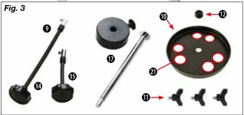
Durchmesser: 3.476 km
About this Instruction Manual
Please read the safety instructions in this manual carefully. To avoid damage to the unit and the risk of injury, only use this product as described in the manual.
Keep the instruction manual handy so that you can easily look up information on all the functions.

DANGER!
You will find this symbol in front of every section of text which deals with the risk of severe injury or even death in the event of improper use.

ATTENTION!
You will find this symbol in front of every section of text which deals with the risk of damage to property or the environment.
Intended Use
This product is intended only for private use.
It was developed for the magnified display of things in nature.
General Warning

RISK OF BLINDNESS!
Never use this device to look directly at the sun or in the direct proximity of the sun. There is a RISK OF BLINDNESS!

RISK OF CHOKING!
Children should only use the device under adult supervision. Keep packaging material (plastic bags, rubber bands, etc.) out of the reach of children! There is a RISK OF CHOKING!

FIRE RISK!
Do not place the device — in particular the lenses — in direct sunlight. The concentration of light could cause fire.

ATTENTION!
Do not disassemble the device. In the event of a defect, please contact your dealer. He will contact the Service Centre and can send the device in to be repaired, if necessary.
Do not expose the device to high temperatures.

Privacy PROTECTION!
This device is intended only for private use. Please heed the privacy of other people. Do not use the device to look into apartments, for example.
Accessories may vary depending on the model.
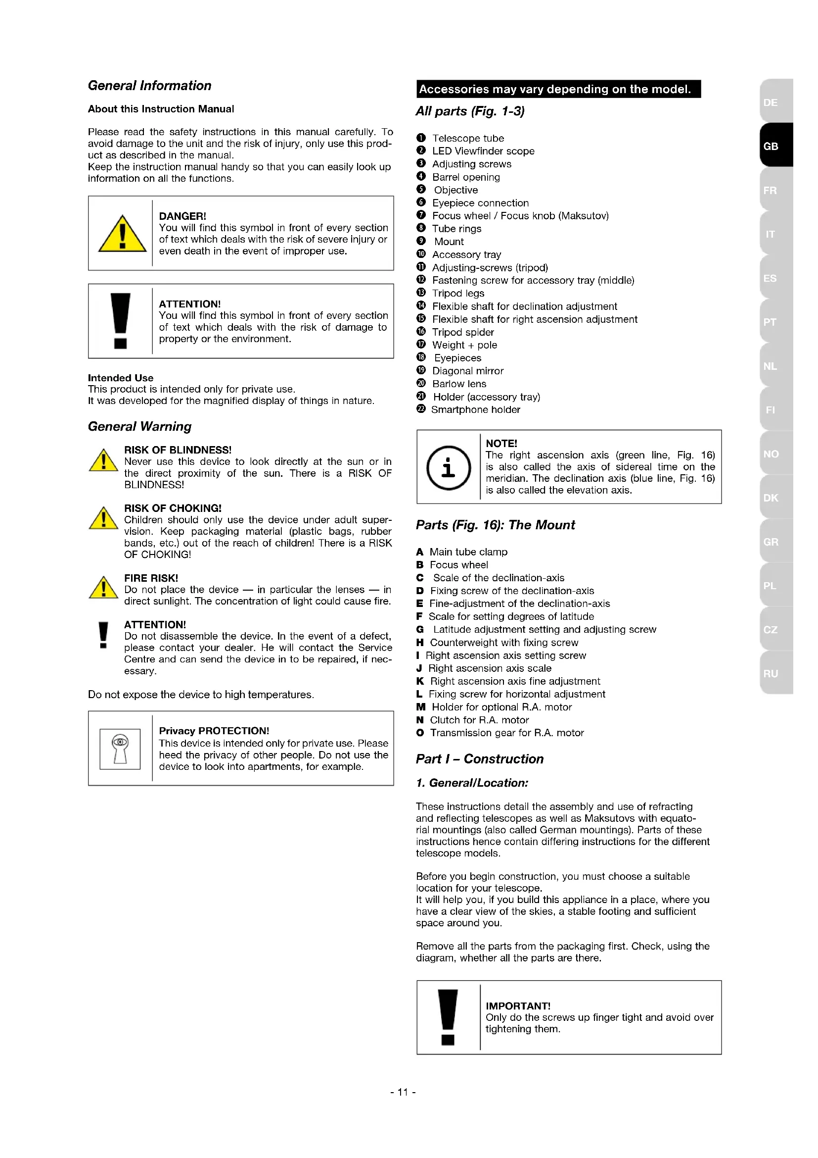
All parts (Fig. 1-3)
① Telescope tube
② LED Viewfinder scope
③ Adjusting screws
4 Barrel opening
5 Objective
⑥ Eyepiece connection
⑦ Focus wheel / Focus knob (Maksutov)
8 Tube rings
9 Mount
10 Accessory tray
⑪ Adjusting-screws (tripod)
⑫ Fastening screw for accessory tray (middle)
⑬ Tripod legs
14 Flexible shaft for declination adjustment
15 Flexible shaft for right ascension adjustment
16 Tripod spider
⑰ Weight + pole
18 Eyepieces
19 Diagonal mirror
20 Barlow lens
21 Holder (accessory tray)
22 Smartphone holder

NOTE!
The right ascension axis (green line, Fig. 16) is also called the axis of sidereal time on the meridian. The declination axis (blue line, Fig. 16) is also called the elevation axis.
Parts (Fig. 16): The Mount
A Main tube clamp
B Focus wheel
C Scale of the declination-axis
D Fixing screw of the declination-axis
E Fine-adjustment of the declination-axis
F Scale for setting degrees of latitude
G Latitude adjustment setting and adjusting screw
H Counterweight with fixing screw
■ Right ascension axis setting screw
J Right ascension axis scale
K Right ascension axis fine adjustment
L Fixing screw for horizontal adjustment
M Holder for optional R.A. motor
N Clutch for R.A. motor
- Transmission gear for R.A. motor
Part I - Construction
1. General/Location:
These instructions detail the assembly and use of refracting and reflecting telescopes as well as Maksutovs with equatorial mountings (also called German mountings). Parts of these instructions hence contain differing instructions for the different telescope models.
Before you begin construction, you must choose a suitable location for your telescope.
It will help you, if you build this appliance in a place, where you have a clear view of the skies, a stable footing and sufficient space around you.
Remove all the parts from the packaging first. Check, using the diagram, whether all the parts are there.

IMPORTANT!
Only do the screws up finger tight and avoid over tightening them.
2. Tripod
The tripod legs are pre-installed and already connected to the tripod head (Fig. 5, X) and tripod spider (Fig. 1, 16). Remove the tripod from it's packaging and place it upright with the feet at the base. Take two of the legs and carefully pull them apart until they are in the fully open position. The entire weight of the tripod rests on one leg during this procedure. Then set the tripod upright again.
Now extend each individual tripod leg to the desired length (see Fig. 4) and then tighten the clamping screw on each (Fig. 4, 11) (a total of 3) until they are all hand tight. Do not over-tighten them. The clamping screws serve to set the tripod leg interior segments to the desired height.

NOTE!
The right ascension axis (green line, Fig. 16) is also called the axis of sidereal time on the meridian. The declination axis (blue line, Fig. 16) is also called the elevation axis.
3. Mounting
Next the mounting (Fig. 1, 9) is fastened to the tripod head (Fig. 5, X). To do so insert the mounting from above in the tripod head and turn the knurled screw hand tight from below.
First prepare the mount (Fig. 1, 9), put the weight on the weight shaft pole (Fig. 7, X) and then screw it securely into the mount from below.
The tube ring (Fig. 1+3, 8) should now be placed on the mount and fixed with the screw (Fig. 8, X).
Maksutov optics have no tube-clamp. The rail is placed directly on the mount.
4. Accessory tray:
First unscrew the fastening screw for the accessory tray (12). Now insert the accessory tray (10) as seen in Fig. 6. Lastly screw the fastening screw (12) in the middle tightly, to secure the accessory tray (10).
5. Tube:
5.1 To mount the telescope tube (Fig. 1, 1) you undo the screw on the tube ring (Fig. 9, X) and open up the ring.
5.2 Now you place the tube in the centre of ring and close the ring up. Now secure the mounting by tightening the screw.
Note: The main tube clamp may have 2 screws depending on model (Fig. 9b). Mounting the main tube is in principle as given here.
6. Inserting the eyepiece
6.1. On refracting telescopes
Two eyepieces (Fig. 2, 18) and a star diagonal prism (Fig. 2, 19) are supplied as standard with this telescope.
With the eyepieces, you can decide which magnification you want for your telescope.
Before you insert the eyepiece and the star diagonal prism, you must remove the dust-protection-cap from the eyepiece connection tube (Fig. 1, 6).
Loosen the screw (Fig. 12, X) on the eyepiece connection tube and insert the star diagonal prism. Retighten the screw (Fig. 12, X) on the eyepiece connection tube.
Then open and close the clamping screw (Fig. 13a, X) to fasten the 20 mm eyepiece in the zenith mirror in the same way.
Make sure that the eyepiece is pointing vertically upwards. Otherwise loosen the screw (Fig. 12, X) on the eyepiece connection tube and rotate the star diagonal prism into the vertical position.
6.2. On reflecting telescopes
Please loosen the clamping screw on the eyepiece supports (Fig. 1, 6). Remove the eyepiece supplied (Fig. 2, 18) with the 20 mm maximum focal length and insert it directly in the eyepiece supports. Hand tighten the clamping screws (Fig. 3b, X). Remove the dust cap from the main tube end.
RISK OF BLINDNESS!
Never use this device to look directly at the sun or in the direct proximity of the sun. There is a RISK OF BLINDNESS!
7. Assembling the LED Viewfinder scope
Note: The LED Viewfinder has a battery safeguarded against discharge with plastic foil when shipped. This must be removed before first use (Fig.1d).
Viewfinder scope assembly -
LED Viewfinder scope with Quick Insert
The LED Viewfinder scope (Fig. 1a) and mounting constitute a single unit. Slide the foot of the LED Viewfinder scope completely into the appropriate base on the telescope main tube (Fig. 10, X). The Viewfinder scope mounting will snap in place. Important. Make sure the LED Viewfinder scope lens points towards the main tube end (Fig. 1, 4).
8. Aligning the Viewfinder scope
The LED Viewfinder scope must be adjusted before use. This means that the LED Viewfinder scope and the telescope tube must be aligned in parallel.
Insert the eyepiece with the greatest focal length in the zenith mirror (Fig. 13a, refracting telescopes only) or directly in the eyepiece supports (Fig. 13b, reflecting telescopes only). Point the telescope at a significant object approximately 300 meters away (e.g. house gable, church tower top, etc.) and adjust until it appears in the centre of the field of vision (Fig. 15 A).
Then turn the LED Viewfinder scope (Fig. 1, 2) on using the On/Off switch (Fig. 1b, Z). Select setting „2“ in daylight, setting „1“ for nighttime.
Look through the LED Viewfinder scope and align it by turning the horizontal (Fig. 1b, X) and vertical (Fig. 1b, Y) adjustment screws until you see the red dot in the centre of the image (Fig. 15, C). Viewfinder scope and telescope are now adjusted to one another.
9. Protection-caps:
In order to protect the inside of your telescope from dust and filth, the tube opening is protected by a dust-protection-cap.
For observation remove the cap from the opening.
10. Flexible shafts
To ease precise adjustment of the declination and right ascension axes flexible shafts are installed in the holding devices of both axes provided for the purpose (Fig. 14, X).
The long flexible shaft is mounted parallel to the telescope barrel (Fig. 1, 14). It is secured in place with a clamping screw in the axis notch provided.
The short flexible shaft is 1, 15) is mounted laterally. It too is secured in place with a clamping screw in the axis notch provided.
Your telescope is now ready for use.
Part II - Handling
1. Telescope mount:
The following points of information are important for positioning and tracking accuracy of your telescope during night time observation.
Your telescope has a so called equatorial mount. The main attribute of this mount is that it has two perpendicular axes which rotate to one another. (Fig 16, a+b).
The so-called right ascension axis (or RA or axis of sidereal time on the meridian) (Fig. 16, b) must be aligned parallel to the earth's polar axis (Fig. 26, c). The coordinates are found in e.g. celestial charts and programs.
Manually operate the right ascension axis via the flexible shaft (Fig. 1, 15) to constantly compensate for the earth's rotation by turning it in the opposite direction.
As this axis must thus constantly be moved in a controlled manner using the flexible shaft an electric tracking accessory would be sensible (the necessary equipment for this is already installed - sh. parts - assembly)
2. Setup:
A dark place is essential for observations because light of all kinds (e.g. street lamps) disturb the visible details of the sky. If you leave a bright room at night, your eyes need approximately 20 minutes to reach full night adaptation. After this time, your observations can be started.
Don't observe from enclosed areas and put your telescope in location, with the accessories, 30 mins before beginning observation, in order to guarantee a temperature balance.
You should also make sure that the telescope is placed on a stable and even ground.
3. Balance:
To avoid demages from sensitive parts of the mount, the two axes must now be balanced before observation.
I.e. the declination axis and the horary axis are correct, to make working of the telescope easy and precise.
The horary axis is balanced by loosening the fixing screws (Fig. 16 I) and tilting the weight pole into a horizontal position. Now adjust the counterweight (Fig. 16 H) on the pole, until the tube and the weight remain in this horizontal position. Retighten the fixing screw (Fig. 16 I) on the horary axis.
The declination axis is balanced by loosening the fixing screw (Fig. 16 D) on the declination axis. Then loosen the screws on the tube mounting (Fig. 16 A) and move the tube as long as it remains in a horizontal position. Don't forget to retighten the fixing screws again.
4. Adjustment:
To set the latitude axis (Fig. 16, F) (polar height) loosen the fixing screw (Fig. 18, X) and adjust the polar height using the adjusting screw (Fig. 18, Y).
The latitude scale has to be adjusted according the local latitude (e.g. Munich 48°, Hamburg 53°)
Don't forget to tighten the fixing screw afterwards. Now set the Declination axis (Fig. 16 C) to 90^ by loosening and retightening the screw (Fig. 16 D). The telescope tube is now pointing to the celestial pole.

NOTE!
The latitude of your observation site can be found in maps or in the internet. A good source of information is www.heavens-above.com. After checking “anonymous user” > “select” you may choose your land and city.
5. Polar alignment
Align the telescope with the barrel opening at the front to north. To do this loosen the fastening screw (Fig. 19). You can then turn the barrel until it faces exactly northwards. If necessary, use a compass. Then tighten the fastening back up again.
Examine whether your telescope is mounted as shown in Fig. 28. The counterweight (Fig. 28 X) points to the floor and makes together with the tube a vertical axis.
In this position Polaris is visible in the viewfinder; it is the brightest star in the polar region (Fig. 27). If it is also seen in the field of view of the 20 mm eyepiece, polar alignment is reached.
This alignment requires little patience but results in accurate pointing.
The declination scale should now be set to "9" (90°). After doing this, you can use the dec. and R.A. scale to find celestial objects (also see part II - 13).
Once adjusted as above you can utilise the celestial object search facility using the scales (see also 3.1. Feasible Observation Objects).
6. Viewfinder scope
Your telescope is now roughly aligned and set.
To arrive at a comfortable observation position carefully undo the main tube mounting screws (Fig. 9, X) until you can rotate the telescope main tube. Move eyepiece and LED Viewfinder scope until the position is comfortable for you.
Fine adjustment is done with the aid of the Viewfinder scope. Look through the LED Viewfinder and try to align it with the polar star (Fig. 27) with the help of the red dot (Fig. 15). In precisely adjusting your telescope you will find the shaft (Fig. 16, K) of the hour axis (Fig. 16, b) and that (Fig. 16, E) of the declination axis (Fig. 16, a) helpful.
7. Observation
Once you have set the polar star in your LED Viewfinder scope you will be able to view it through your telescope eyepiece.
If necessary, you can with help of the flexible handles align the star more exactly, just as you can adjust the definition by using the focussing wheel (7).
Furthermore, you can now, by changing the eyepiece, increase the magnification. Note that the magnification of the stars can hardly be seen.

NOTE!
Eyepieces enlarge the (not directly visible) picture of the telescope's prime focus. The less the eyepiece's focal lengths is, the stronger is the magnification. So various eyepieces are needed to reach different magnifications. Begin every observation with a low magnification (20mm eyepiece).
8. Find a star:
Initially it will be difficult for you to find your bearings in the firmament, since the stars and the constellations are always moving and according to season, date and time their position in the heavens will change. The pole star is the exception. It is a fixed star and the starting point for all star maps.
At the beginning, you should look at some well known constellations and star groups order that are visible the whole year over. The position of the heavenly bodies is however dependent on date and time.
If you have aligned your telescope accurately on one of these stars, you will find that it has vanished your visual field after a few minutes. To even out this effect, you must turn the flexible handle (Fig. 16 K) the horary axis and your telescope will follow the trajectory of this star.
9. Part circles:
Stars and other heavenly bodies are positioned in the heavens by coordinates. The place of a star is fixed in the universe by the rectascension (horary) and by the declination.
Declintion (Fig. 16 C) is the spacing of a heavenly body from the Heaven's equator, in angle degrees. To the north of the equator, the degree number is positive. If the star is to the south of the equator, the degree number is negative.
Rectascension (Fig. 16 M) a measured distance of a star from the heavens equator in sidereal (star) time. The vernal equinox is the point where the ecliptic meets the equator (Fig. 26 e) at the beginning of spring. The value of the daily heavenly revolutions is counted in the tempo of a 24 hour clock.
For more accurate information look at your star maps and corresponding compartment-literature (special-accessories).
10. Accessories
Your telescope is supplied with a number of accessories as standard (Fig. 2). Depending on model this may include the following.
10.1. Eyepieces
Change eyepieces to change your telescope's magnification.
Formula for calculating magnification:
Focal length of the telescope : focal length of the eyepiece = magnification
Beispiele:
| Focal length telescope | Focal length eyepiece | Magnification | Magnification with 3x Barlow lens |
| 700 mm 20 m | m 35X 105X | ||
| 700 mm 4 mm | 175X 525X |
10.2. Zenith mirror (refraction telescope only)
The zenith mirror reverses (Fig. 2,19) reverses the image (mirror image) and is therefore used only for celestial observation.
10.3. Barlow lens
A Barlow increases magnification three times over.
10.3.1 Assembling and using refracting telescopes
If you use a refracting telescope the Barlow lens should only be inserted in the zenith mirror (Fig. 13a, X). Remove the eyepiece from the zenith mirror and replace it with the Barlow lens. Then first insert the eyepiece with the greatest focal length and then hand tighten the clamping screw to affix it in place (Fig. 24).
10.3.2 Assembling and using reflecting telescopes/Maksutovs If you use a reflecting telescope please undo the clamping screw on the eyepiece supports (Fig. 13b, X) and remove the eyepiece from those supports. Then insert the Barlow lens straight in the supports and hand tighten the clamping screw. Finally first insert the eyepiece with the greatest focal length in the Barlow lens and then fasten it in place with the clamping screw (Fig. 24).
10.4 Smartphone holder
Insert the eyepiece into the smartphone holder and tighten the screw (Fig. 25, X) to the bracket firmly. Then set the smartphone holder with the eyepiece into the eyepiece connection (6) or the diagonal mirror (19) (refractor telescopes) and tighten the clamping screws (Fig. 25, Y) by hand firmly. Now start your smartphone camera app and press your smartphone on the suction cups. Make sure that it is properly secured. The camera should rest just above the eyepiece. Place the smartphone exactly over the eyepiece, so that the image is exactly centered on your display. It may be necessary to use the zoom function to fill out the whole screen of your smartphone. The suction cups must be dry, clean and free from all kinds of dust and dirt. We assume no responsibility for dropped and broken smartphones due to incorrect handling.
11. Dismantling:
After a hopefully interesting and successful observation, it is recommended that you store the entire telescope in a dry, well aired area. On some telescopes the tripod and mount can easily be separated. The adjustments to the mount will remain intact. Don't forget to put the dust-protection-caps onto the tube opening and onto the eyepiece connection. Also, you should stow all the eyepieces and optical accessories into their corresponding receptacles.

NOTES on cleaning
Clean the lenses (eyepiece and/or lens) with a soft and lint-free cloth only (e.g. microfibre). Do not apply excess pressure to the cloth so as to avoid scratching the lenses.
To remove more stubborn dirt, moisten the cleaning cloth with an eyeglass-cleaning solution and wipe the lenses gently.
Protect the device from dust and moisture! After use - in particular in situations of high humidity - let the device acclimatize for a short period of time, so that the residual moisture can dissipate.
Part III - Appendix
1. Possible observation targets
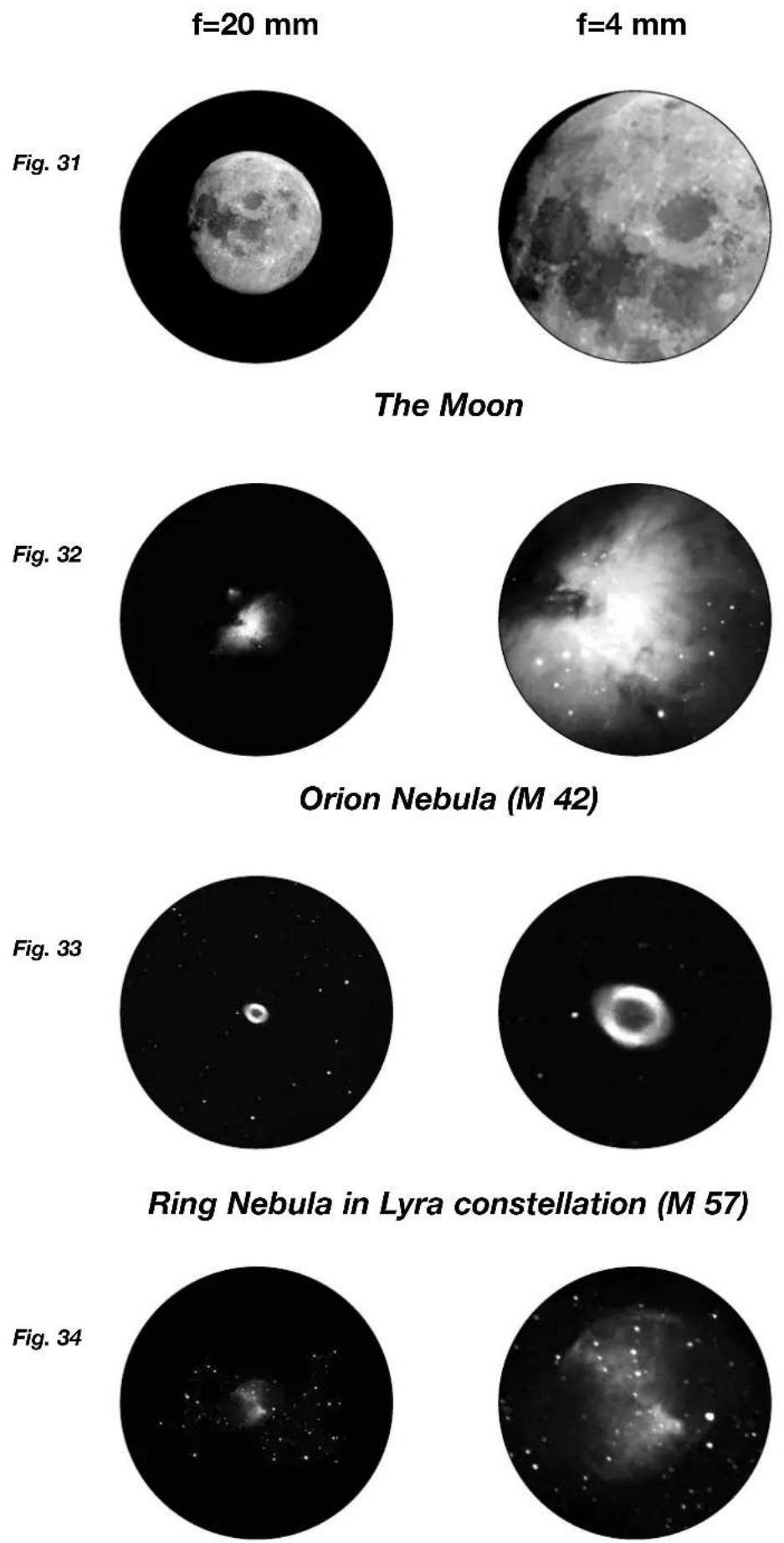
In the following, we like to present to you a choice of very interesting and easy-to-find celestial objects. On the depending pictures at the end of the manual you will see how they will appear in the eyepiece of your telescope:
The moon (Fig. 31)
The moon is the only natural satellite of the earth.
Diameter: 3,476 km
Distance: 384,000 km (average)
The moon is well-known since thousands of years. He is the second-brightest celestial object after the sun. Because the moon circles around the earth, he changes periodically its inclination to the sun; therefore we see changing phases. The time for one complete lunation is 29.5 days (709 hours).
Constellation Orion: The great Orion nebula / M 42 (Fig. 32)
Right Ascension: 05h 33' (hours : minutes)
Declination: -05^ 25' (Degrees : minutes)
Though it is 1,600 light years away, the Orion nebula (M 42) is the brightest nebula object at the sky – visible even with naked eyes and a worthwhile object for telescopes of all kinds and sizes. It consists of a gigantic cloud of hydrogen gas with a diameter of hundreds of light years, taking a field on the sky of 10^ .
Constellation Lyra: The Ring Nebula / M 57 (Fig. 33)
Right Ascension: 18h 52'
Declination: +32° 58'
Distance: 4,100 light years
The famous Ring Nebula is often called the prototype of planetary nebulae; he belongs to the northern hemisphere summer sky's pieces of splendour. Recent investigations have shown that he is a ring of light-emitting matter that surrounds its central star (only visible in bigger telescopes). If one could look onto its top, he would see a structure like the Dumbbell Nebular / M 27
Constellation Vulpecula (little fox):
The Dumbbell Nebula / M 27 (Fig. 34)
Right Ascension: 19h 59'
Declination: +22° 43'
Distance: 1,250 light years
The Dumbbell Nebula / M 27 was the first planetary nebula ever found. On July 12th, 1764, Charles Messier discovered this new and fascinating class of objects. We can see it directly from its equatorial pane. If it could be viewed from top, we would appear like the Ring Nebula / M 57. This Object can even be viewed at average weather conditions at low magnifications.
2. Troubleshooting:
Mistakes:
Help:
No picture Remove dust protection cap and sunbathe-shield from the objective opening.
Blurred picture Adjust focus using focus ring
Focus knob The Maksutov design may require more than 20 revolutions at the focusing knob to obtain a sharp image.
No focus possible
Wait for temperature to balance out
Bad picture Never observe through a glass surface
Viewing object visible Adjust finder (See Part I: in the finder, but not 8. Construction) through the telescope
Heaviness in the flexible Telescope and counter handles on the axis weight not balanced over the shaft Despite using star The star diagonal prism diagonal prism should be vertical in the picture is the eyepiece connection "crooked"

DISPOSAL
Dispose of the packaging materials properly, according to their type (paper, cardboard, etc). Contact your local waste disposal service or environmental authority for information on the proper disposal.
Please take the current legal regulations into account when disposing of your device. You can get more information on the proper disposal from your local waste disposal service or environmental authority.
Downloads:
- Astronomy software
- Moon map
- Instruction Manual
The regular guarantee period is 2 years and begins on the day of purchase. To benefit from an extended voluntary guarantee period as stated on the gift box, registration on our website is required.
You can consult the full guarantee terms as well as information on extending the guarantee period and details of our services at www.bresser.de/warranty_terms.
LUNE (illustration 31)
BESCHERMING van privacy!
Del I - Sammensening
1. Generelt/lassering:
natural_image
Close-up of a black telescope mounted on a tripod, labeled 'Fig. 17' (no other text or symbols visible)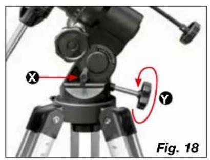
natural_image
Close-up of a tripod-mounted optical instrument with labeled points X and Y, showing mechanical components and motion arrows (no text or symbols beyond labels)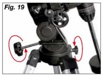
natural_image
Close-up of a camera setup with mechanical components and red circular annotations (no readable text or symbols)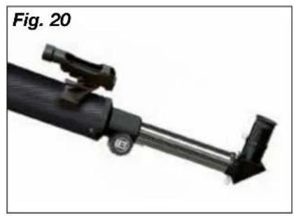
natural_image
Close-up of a black mechanical lever with attached bracket and adjustment knob (no text or symbols visible)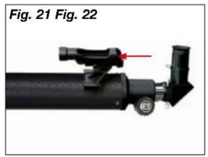
natural_image
Close-up of a mechanical device with a red arrow pointing to a component, labeled Fig. 21 and Fig. 22 (no text or symbols on the device itself)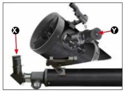
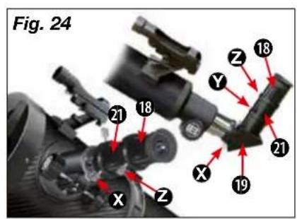
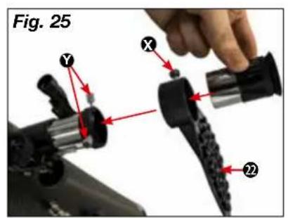
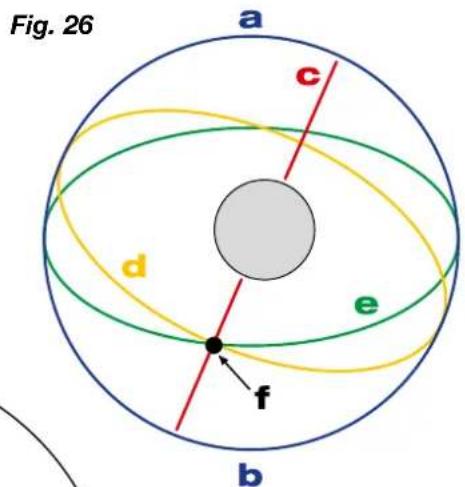
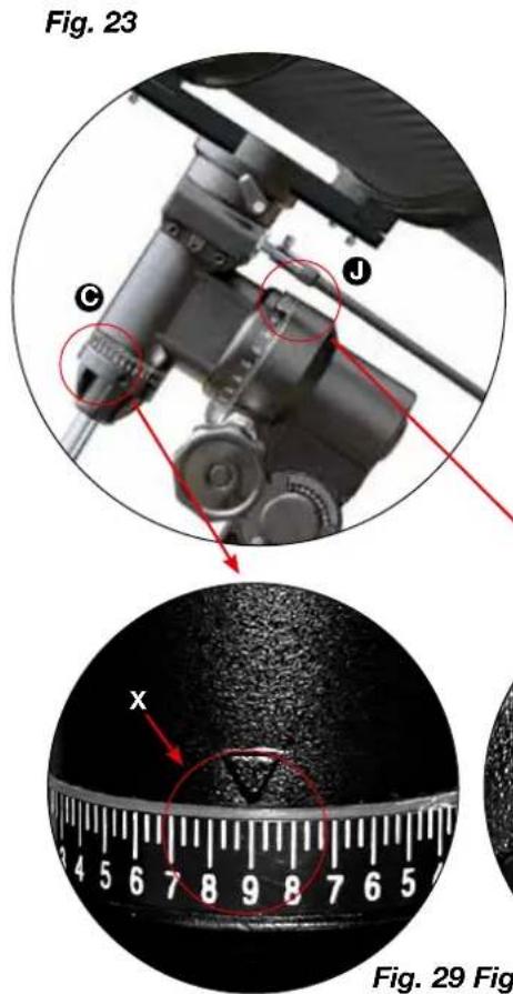
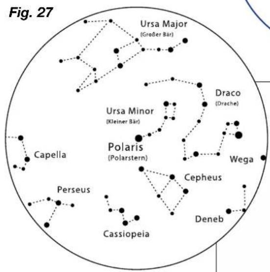
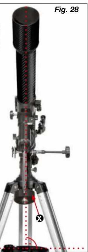
Fig. 29 Fig. 30
Dumbbell Nebula in the Vulpecula (Fox) constellation (M 27)
natural_image
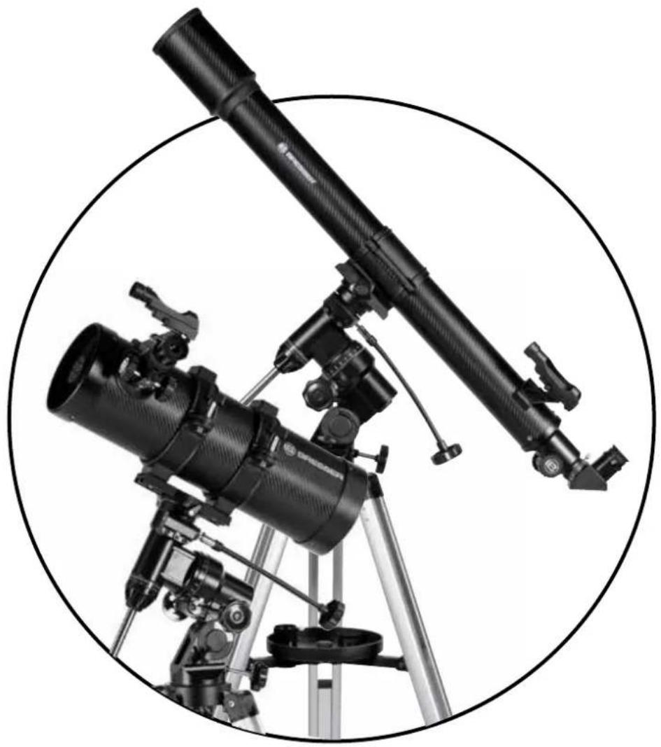
Black-and-white photo of a large telescope mounted on a tripod, enclosed in a circular frame (no text or symbols visible)
BRESSER®
Bresser GmbH
Gutenbergstr. 2 · DE-46414 Rhode Germany

- (FR) AVERTISSEMENT!
- About this Instruction Manual
- DANGER!
- ATTENTION!
- Intended Use
- General Warning
- RISK OF BLINDNESS!
- RISK OF CHOKING!
- FIRE RISK!
- Privacy PROTECTION!
- Accessories may vary depending on the model.
- All parts (Fig. 1-3)
- NOTE!
- Parts (Fig. 16): The Mount
- Part I - Construction
- General/Location:
- IMPORTANT!
- Tripod
- Mounting
- Accessory tray:
- Tube:
- Inserting the eyepiece
- On refracting telescopes
- On reflecting telescopes
- Assembling the LED Viewfinder scope
- Viewfinder scope assembly -
- LED Viewfinder scope with Quick Insert
- Aligning the Viewfinder scope
- Protection-caps:
- Flexible shafts
- Part II - Handling
- Telescope mount:
- Setup:
- Balance:
- Adjustment:
- Polar alignment
- Viewfinder scope
- Observation
- Find a star:
- Part circles:
- Accessories
- Eyepieces
- Formula for calculating magnification:
- Zenith mirror (refraction telescope only)
- Barlow lens
- Assembling and using refracting telescopes
- Smartphone holder
- Dismantling:
- NOTES on cleaning
- Part III - Appendix
- Possible observation targets
- The moon (Fig. 31)
- Constellation Orion: The great Orion nebula / M 42 (Fig. 32)
- Constellation Lyra: The Ring Nebula / M 57 (Fig. 33)
- Constellation Vulpecula (little fox):
- The Dumbbell Nebula / M 27 (Fig. 34)
- Troubleshooting:
- Mistakes:
- Help:
- DISPOSAL
- Downloads:
- LUNE (illustration 31)
- BESCHERMING van privacy!
- Del I - Sammensening
- Generelt/lassering:
- BRESSER®
Brand : BRESSER
Model : CLASSIC 60900 EQ
Category : Telescope