
STELLAR 60800 AZ - Telescope BRESSER - Free user manual and instructions
Find the device manual for free STELLAR 60800 AZ BRESSER in PDF.
| Product Type | Telescope |
| Brand | Bresser |
| Model | STELLAR 60800 AZ |
| Category | Telescope |
| Mount Type | Azimuth mount (alt-azimuth) |
| Optical Type | Refractor (lens) |
| Objective Diameter | 60 mm |
| Focal Length | 800 mm |
| Maximum Magnification | 200x (4mm eyepiece) or 600x with 3x Barlow lens |
| Accessories Included | 20mm and 4mm eyepieces, LED finder, star diagonal, 3x Barlow lens, smartphone adapter, accessory tray |
| Power Supply | CR2032 battery for LED finder |
| Tripod Height (max) | Approx. 120 cm |
| Tube Length | Approx. 70 cm |
| Weight | Approx. 3.5 kg |
| Safety | Never look at the sun – risk of blindness |
| Cleaning | Soft, lint-free cloth (microfiber) possibly moistened with glasses cleaner |
| Storage | Dry and ventilated place, dust caps on |
| Warranty | 2 years (extension possible upon registration at www.bresser.de/warranty_terms) |
Frequently Asked Questions - STELLAR 60800 AZ BRESSER
User questions about STELLAR 60800 AZ BRESSER
0 question about this device. Answer the ones you know or ask your own.
Ask a new question about this device
Download the instructions for your Telescope in PDF format for free! Find your manual STELLAR 60800 AZ - BRESSER and take your electronic device back in hand. On this page are published all the documents necessary for the use of your device. STELLAR 60800 AZ by BRESSER.
USER MANUAL STELLAR 60800 AZ BRESSER
Never attempt observing the sun with this telescope! Especially keep it in mind while the telescope is used by children! Observing the sun – even for a very short time – will cause blindness! Packing material (plastic bags, rubber bands etc.) has to be kept out of reach of children!
(FR) AVERTISSEMENT!
natural_image
Close-up of a mechanical component with a red circle highlighting a specific area, labeled 'Fig. 1b' (no text or symbols on the object itself)Fig. 2 Fig. 3
20
19
22
natural_image
Close-up of a mechanical clamp or clip assembly with red arrows indicating movement, labeled 'Fig. 6' (no text or symbols on the diagram itself)
natural_image
Mechanical assembly diagram showing a bracket with a red arrow indicating a joint or connection point (no text or symbols present)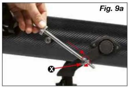
natural_image
Close-up of a mechanical component with a labeled part (Y) and a figure in the background, no readable text or symbols present.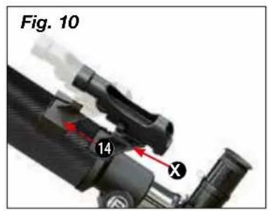
natural_image
Close-up of a hand holding a small tool with red annotation arrows, next to a black mechanical component (no text or symbols visible)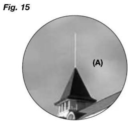
natural_image
Circular black-and-white photo of a church tower with a pointed spire, labeled (A), against a cloudy sky background.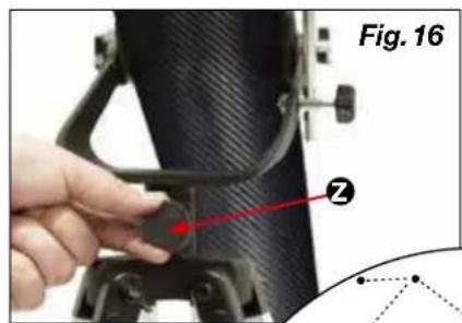
natural_image
Close-up of a black bicycle boom lever with attached bracket (no visible text or symbols)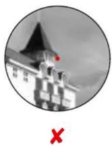
natural_image
Black-and-white circular image of a building with a red flag on top and a red X symbol below (no text or symbols on the main structure)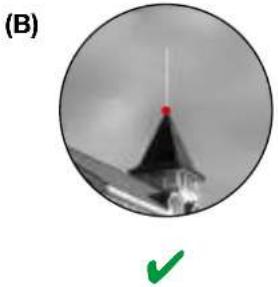
natural_image
Circular grayscale image showing a conical object with a red dot and a green checkmark below (no text or symbols)
flowchart
graph TD
    A["Ursa Major (Großer Bär)"] --> B["Capella"]
    C["Ursa Minor (Kleiner Bär)"] --> D["Polaris (Polarstern)"]
    E["Draco (Drache)"] --> F["Wega"]
    G["Caspiopeia"] --> H["Perseus"]
    I["Cepheus"] --> J["Deneb"]
    K["Desferent"] --> L["Desferent"]
Durchmesser: 3.476 km
About this Instruction Manual
Please read the safety instructions in this manual carefully. To avoid damage to the unit and the risk of injury, only use this product as described in the manual.
Keep the instruction manual handy so that you can easily look up information on all the functions.

DANGER!
You will find this symbol in front of every section of text which deals with the risk of severe injury or even death in the event of improper use.

ATTENTION!
You will find this symbol in front of every section of text which deals with the risk of damage to property or the environment.
Intended Use
This product is intended only for private use.
It was developed for the magnified display of things in nature.
General Warning

RISK OF BLINDNESS!
Never use this device to look directly at the sun or in the direct proximity of the sun. There is a RISK OF BLINDNESS!

RISK OF CHOKING!
Children should only use the device under adult supervision. Keep packaging material (plastic bags, rubber bands, etc.) out of the reach of children! There is a RISK OF CHOKING!

FIRE RISK!
Do not place the device — in particular the lenses — in direct sunlight. The concentration of light could cause fire.

ATTENTION!
Do not disassemble the device. In the event of a defect, please contact your dealer. He will contact the Service Centre and can send the device in to be repaired, if necessary.
Do not expose the device to high temperatures.

Privacy PROTECTION!
This device is intended only for private use. Please heed the privacy of other people. Do not use the device to look into apartments, for example.
Accessories may vary depending on the model.
All parts (Fig. 1-3)
① Telescope tube
② LED Viewfinder
③ Adjusting screws
4 Barrel opening
5 Objective
⑥ Eyepiece connection
⑦ Focus wheel
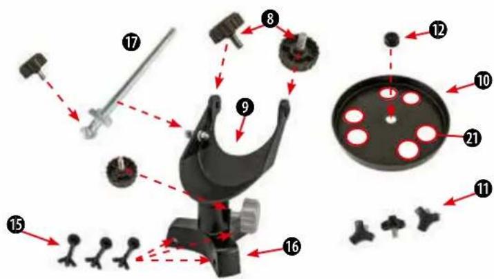
8 Fastening screws (Tube)
9 Mount
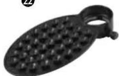
⑩ Accessory tray
⑪ Adjusting-screws (tripod)
⑰ Fastening screw for accessory tray (middle)
⑬ Tripod legs
14 Holder (LED Viewfinder)
⑮ Screws (tripod head)
16 Tripod head
17 Vertical fine adjustment
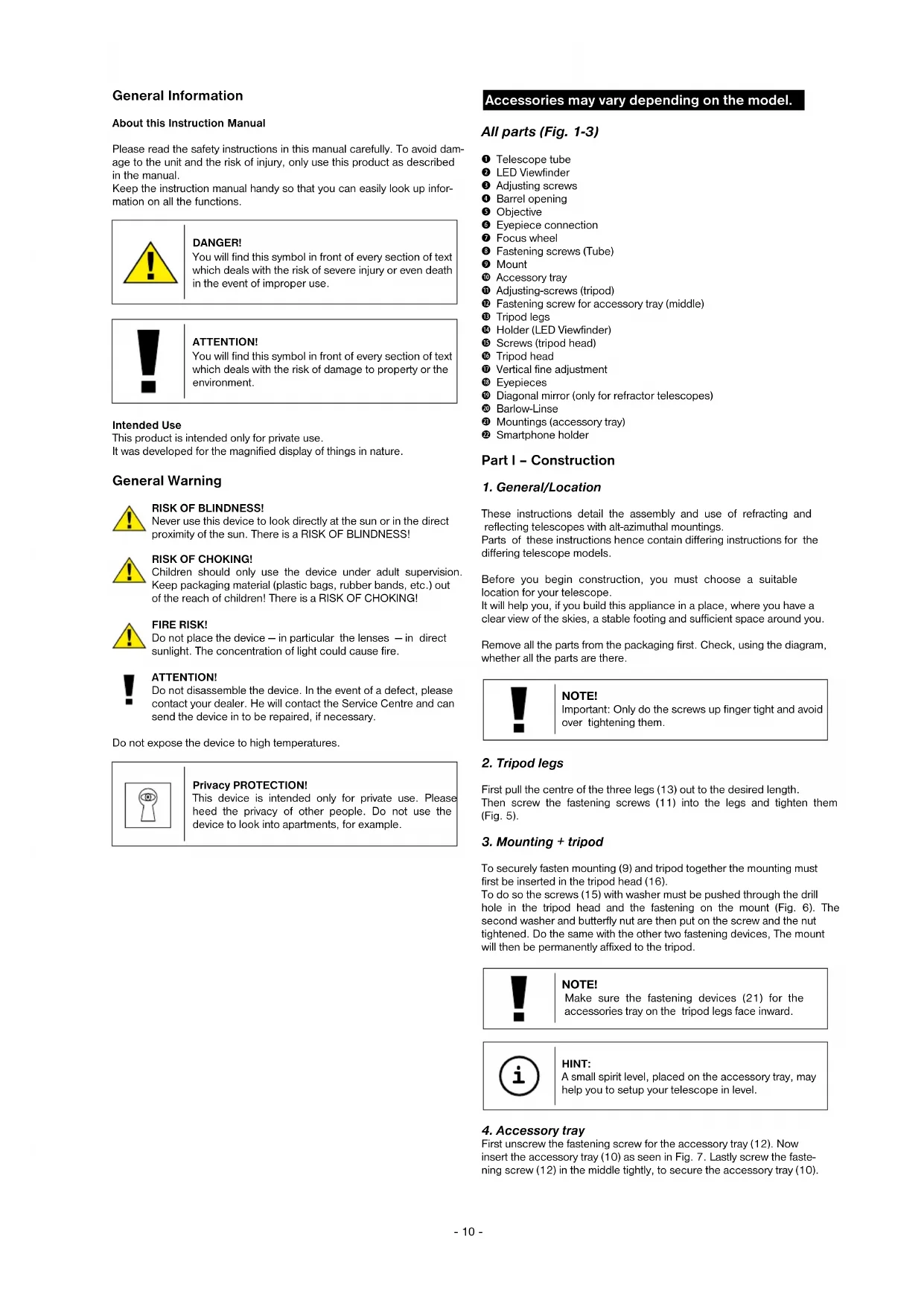
18 Eyepieces
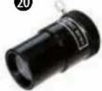
⑲ Diagonal mirror (only for refractor telescopes)
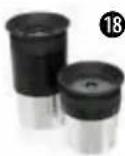
20 Barlow-Linse
21 Mountings (accessory tray)
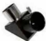
② Smartphone holder
Part I - Construction
1. General/Location
These instructions detail the assembly and use of refracting and reflecting telescopes with alt-azimuthal mountings.
Parts of these instructions hence contain differing instructions for the differing telescope models.
Before you begin construction, you must choose a suitable location for your telescope.
It will help you, if you build this appliance in a place, where you have a clear view of the skies, a stable footing and sufficient space around you.
Remove all the parts from the packaging first. Check, using the diagram, whether all the parts are there.

NOTE!
Important: Only do the screws up finger tight and avoid over tightening them.
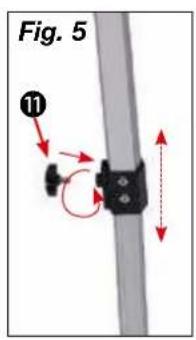
2. Tripod legs
First pull the centre of the three legs (13) out to the desired length. Then screw the fastening screws (11) into the legs and tighten them (Fig. 5).
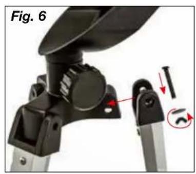
3. Mounting + tripod
To securely fasten mounting (9) and tripod together the mounting must first be inserted in the tripod head (16).
To do so the screws (15) with washer must be pushed through the drill hole in the tripod head and the fastening on the mount (Fig. 6). The second washer and butterfly nut are then put on the screw and the nut tightened. Do the same with the other two fastening devices, The mount will then be permanently affixed to the tripod.

NOTE!
Make sure the fastening devices (21) for the accessories tray on the tripod legs face inward.

HINT:
A small spirit level, placed on the accessory tray, may help you to setup your telescope in level.
4. Accessory tray
First unscrew the fastening screw for the accessory tray (12). Now insert the accessory tray (10) as seen in Fig. 7. Lastly screw the fastening screw (12) in the middle tightly, to secure the accessory tray (10).
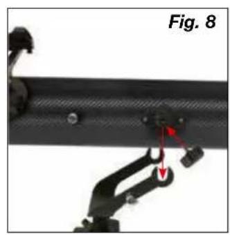
5. Tube
Now hold the telescope main tube (1) as shown in the middle of the alt-azimuth mount (9) and screw the screws (8) into the tube from both sides (Fig. 8).
6. Vertical fine adjustment
To mount the vertical fine adjustment (17) first push the adjustment rod through holding device (X) on the mount (Fig. 9a).
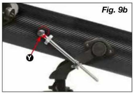
Then undo the screw (Y) for the adjustment rod and insert on the other end of the rod. Then tighten it in place (Fig. 9b).
Important: Do not screw the vertical fine adjustment fastening screw too tightly. If you do the main tube will not be vertically adjustable.
RISK OF BLINDNESS!
Never use this device to look directly at the sun or in the direct proximity of the sun. There is a RISK OF BLINDNESS!
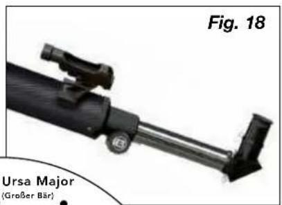
7. Assembling the LED Viewfinder
Note: The LED Viewfinder scope has a battery safeguarded against discharge with plastic foil when shipped. This must be removed before first use (fig.1d).
Viewfinder scope assembly:
LED Viewfinder scope with Quick Insert
The LED finder scope (Fig. 1a) and mounting constitute a single unit. Slide the foot of the LED finder scope completely into the appropriate base on the telescope main tube (Fig. 10, X). The finder scope mounting will snap in place.
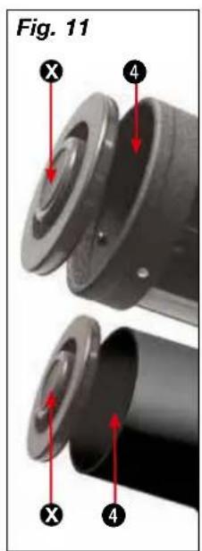
Important: Make sure the LED finder scope lens points towards the main tube end (Fig. 1, 4).
8. Aligning the finder scope
The LED finder scope must be adjusted before use. This means that the LED finder scope and the telescope tube must be aligned in parallel.
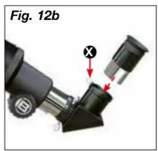
Insert the eyepiece with the greatest focal length in the zenith mirror (Fig. 12b, refracting telescopes only) or directly in the eyepiece supports (Fig. 13, reflecting telescopes only). Point the telescope at a significant object approximately 300 meters away (e.g. house gable, church tower top, etc.) and adjust until it appears in the centre of the field of vision (Fig. 15 A).
Then turn the LED finder scope (2) on using the On/Off switch (Fig. 1b, Z). Select setting „2“ in daylight, setting „1“ for nighttime.
Look through the LED finder scope and align it by turning the horizontal (Fig. 1b, X) and vertical (Fig. 1b, Y) adjustment screws until you see the red dot in the centre of the image (Fig. 15, B). Finder scope and telescope are now adjusted to one another.
9. Protection-caps
In order to protect the inside of your telescope from dust and filth, the tube opening is protected by a dust-protection-cap (Fig. 11, X).
For observation remove the cap from the opening.
10. Inserting the eyepiece
10.1. On refracting telescopes
Two eyepieces (18) and a star diagonal prism (19) are supplied as standard with this telescope.
With the eyepieces, you can decide which magnification you want for your telescope.
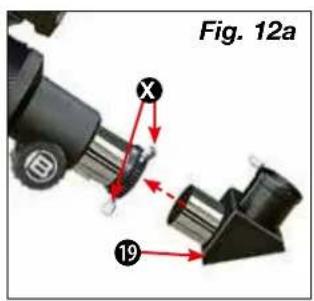
Before you insert the eyepiece and the star diagonal prism, you must remove the dust-protection-cap from the eyepiece connection tube (6). Loosen the screw (Fig. 12a, X) on the eyepiece connection tube and insert the star diagonal prism. Retighten the screw (X) on the eyepiece connection tube.
Then open and close the clamping screw (Fig. 12b, X) to fasten the 20 mm eyepiece in the zenith mirror in the same way.
Make sure that the eyepiece is pointing vertically upwards. Otherwise loosen the screw (Fig. 12a, X) on the eyepiece connection tube and
rotate the star diagonal prism into the vertical position. Remove the dust cap from the main tube end.
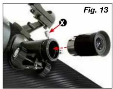
10.2. On reflecting telescopes
Please loosen the clamping screw on the eyepiece supports (6). Remove the eyepiece supplied (18) with the 20 mm maximum focal length and insert it directly in the eyepiece supports. Hand tighten the clamping screws (Fig. 13, X). Remove the dust cap from the main tube end.
Part II - Handling
1. Mount
Your telescope is equipped with an azimuth mount that is easy to use. You can adjust your telescope horizontally and vertically with it.
2. Setup
A dark place is essential for observations because light of all kinds (e.g. street lamps) disturb the visible details of the sky. If you leave a bright room at night, your eyes need approximately 20 minutes to reach full night adaptation. After this time, your observations can be started.
Don't observe from enclosed areas and put your telescope in location, with the accessories, 30 mins before beginning observation, in order to guarantee a temperature balance.
You should also make sure that the telescope is placed on a stable and even ground.
3. Vertical and horizontal adjustment
3.1. Vertical adjustment
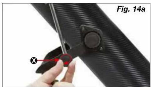
Undo the fastening screw (Fig. 14a, X) and move the tube up or down. Once you find the right setting turn the fastening screw hand tight. This makes the adjustment a fixed one.
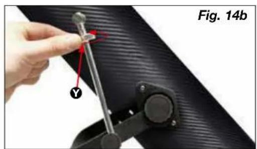
Minor changes can be carried out by slight turns of the adjustment wheel (Fig. 14b, Y). Before re-adjusting undo the fastening screw (Fig. 14a, X).
3.2. Horizontal adjustment
To move the telescope horizontally undo the fastening screw (Fig. 16, Z) and turn the device in the desired direction.
Once you've reached the desired position retighten the fastening screw hand tight
4. Observation
Aim the telescope at the object to be observed. Look through the LED finder scope and centre the object in the middle of the viewing field (red dot) by horizontally and vertically adjusting the telescope.
If you now look through the lens you will see the magnified object.
Turn the focussing wheel to get it into sharp focus if necessary.
You can also change the lens to achieve greater magnification.

HINT:
Start each observation with a low-power lens (20 mm).
5. Finding stars
You will initially have problems orienting yourself in the sky as stars and constellations are in constant movement and change their position depending on the season, date and time.
The polar star is the sole exception. It is a fixed star and the starting point of all stellar maps.
You can see some well-known stars and constellations on the map that are visible throughout the year. The arrangement of the stars is dependent on the date and the time, however.
6. Accessories
Your telescope is supplied with a number of accessories as standard (Fig. 2). Depending on model this may include the following.
6.1. Eyepieces
Change eyepieces to change your telescope's magnification.
Formula for calculating magnification:
Focal length of the telescope : focal length of the eyepiece = magnification
Beispiele:
| Focal length telescope | Focal length eyepiece | Magnification | Magnification with 3x Barlow lens |
| 700 mm 20 m | 35X 105X | ||
| 700 mm 4 mm | 175X525X |
6.2. Zenith mirror (refraction telescope only)
The zenith mirror reverses (19) reverses the image (mirror image) and is therefore used only for celestial observation.
6.3. Barlow lens
A Barlow lens (20) increases magnification three times over.
6.3.1 Assembling and using refracting telescopes
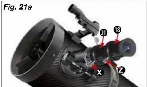
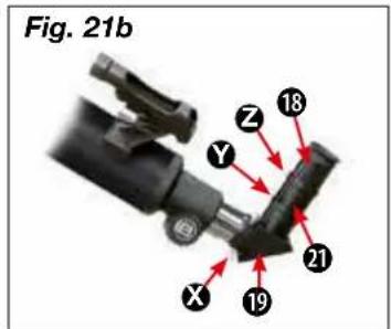
If you use a refracting telescope the Barlow lens should only be inserted in the zenith mirror (Fig. 12a, X). Remove the eyepiece from the zenith mirror and replace it with the Barlow lens. Then first insert the eyepiece with the greatest focal length and then hand tighten the clamping screw to affix it in place (Fig. 21, Z).
6.3.2 Assembling and using reflecting telescopes
If you use a reflecting telescope please undo the clamping screw on the eyepiece supports (Fig. 21, X) and remove the eyepiece from those supports. Then insert the Barlow lens (20) straight in the supports and hand tighten the clamping screw. Finally first insert the eyepiece with the greatest focal length in the Barlow lens and then fasten it in place with the clamping screw (Fig. 21, Z).
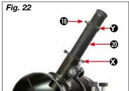
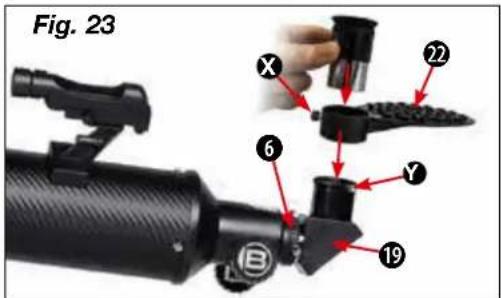
6.4 Smartphone holder
Insert the eyepiece into the smartphone holder and tighten the screw (Fig. 23, X) to the bracket firmly. Then set the smartphone holder with the eyepiece into the eyepiece connection (6) or the diagonal mirror (19) (refractor telescopes) and tighten the clamping screws (Fig. 23, Y) by hand firmly. Now start your smartphone camera app and press your smartphone on the plate. Make sure that it is properly secured. The camera should rest just above the eyepiece. Place the smartphone exactly over the eyepiece, so that the image is exactly centered on your display. It may be necessary to use the zoom function to fill out the whole screen of your smartphone. The suction cups must be dry, clean and free from all kinds of dust and dirt. We assume no responsibility for dropped and broken smartphones due to incorrect handling.
7. Dismantling
After a hopefully interesting and successful observation, it is recommended that you store the entire telescope in a dry, well aired area. On some telescopes the tripod and mount can easily be separated. The adjustments to the mount will remain intact. Don't forget to put the dust-protection-caps onto the tube opening and onto the eyepiece connection. Also, you should stow all the eyepieces and optical accessories into their corresponding receptacles.

NOTES on cleaning
Clean the lenses (eyepiece and/or lens) with a soft and lint-free cloth only (e.g. microfibre). Do not apply excess pressure to the cloth so as to avoid scratching the lenses.
To remove more stubborn dirt, moisten the cleaning cloth with an eyeglass-cleaning solution and wipe the lenses gently.
Protect the device from dust and moisture! After use - in particular in situations of high humidity - let the device acclimatize for a short period of time, so that the residual moisture can dissipate.
Part III - Appendix
1. Possible observation targets
In the following, we like to present to you a choice of very interesting and easy-to-find celestial objects. On the depending pictures at the end of the manual you will see how they will appear in the eyepiece of your telescope:
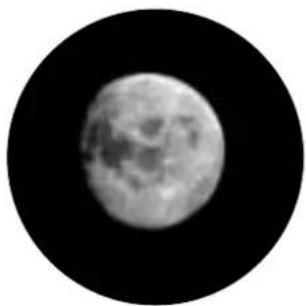
The moon (Fig. 24)
The moon is the only natural satellite of the earth.
Diameter: 3,476 km
Distance: 384,000 km (average)
The moon is well-known since thousands of years. He is the second-brightest celestial object after the sun. Because the moon circles around the earth, he changes periodically its inclination to the sun; therefore we see changing phases. The time for one complete lunation is 29.5 days (709 hours).
Constellation Orion: The great Orion nebula / M 42 (Fig. 25)
Right Ascension: 05h 33' (hours : minutes)
Declination: -05^25' (Degrees : minutes)
Though it is 1,600 light years away, the Orion nebula (M 42) is the brightest nebula object at the sky - visible even with naked eyes and a worthwhile object for telescopes of all kinds and sizes. It consists of a gigantic cloud of hydrogen gas with a diameter of hundreds of light years, taking a field on the sky of 10^ .
Constellation Lyra: The Ring Nebula / M 57 (Fig. 26)
Right Ascension: 18h 52'
Declination: +32° 58'
Distance: 4,100 light years
The famous Ring Nebula is often called the prototype of planetary nebulae; he belongs to the northern hemisphere summer sky's pieces of splendour. Recent investigations have shown that he is a ring of light-emitting matter that surrounds its central star (only visible in bigger telescopes). If one could look onto its top, he would see a structure like the Dumbbell Nebular / M 27
Constellation Vulpecula (little fox):
The Dumbbell Nebula / M 27 (Fig. 27)
Right Ascension: 19h 59'
Declination: +22° 43'
Distance: 1,250 light years
The Dumbbell Nebula / M 27 was the first planetary nebula ever found. On July 12th, 1764, Charles Messier discovered this new and fascinating class of objects. We can see it directly from its equatorial pane. If it could be viewed from top, we would appear like the Ring Nebula / M 57. This Object can even be viewed at average weather conditions at low magnifications.
- Troubleshooting
| Mistakes: | Help: |
| No picture | Remove dust protection cap and sunbathe-shield from the objective opening. |
| Blurred picture | Adjust focus using focus ring |
| No focus possible | Wait for temperature to balance out |
| Bad picture | Never observe through a glass surface |
| Viewing object visible in the finder, but not through the telescope | Adjust finder (See Part II-4) |
| Despite using star diagonal prismthe picture is “crooked” | The star diagonal prism should be vertical in the eyepiece connection |

DISPOSAL
Dispose of the packaging materials properly, according to their type (paper, cardboard, etc). Contact your local waste disposal service or environmental authority for information on the proper disposal.
Please take the current legal regulations into account when disposing of your device. You can get more information on the proper disposal from your local waste disposal service or environmental authority.
Downloads:
- Astronomy software
- Moon map
- Instruction Manual
The regular guarantee period is 2 years and begins on the day of purchase. To benefit from an extended voluntary guarantee period as stated on the gift box, registration on our website is required.
You can consult the full guarantee terms as well as information on extending the guarantee period and details of our services at www.bresser.de/warranty_terms.
BESCHERMING van privacy!
natural_image
Close-up of a black mechanical device with a red arrow pointing to a component (no visible text or symbols)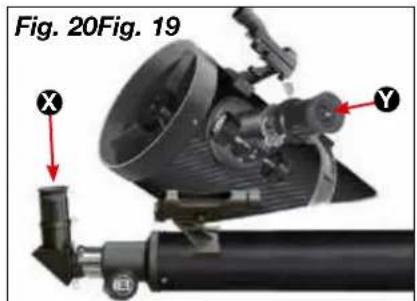
f=20 mm f=4 mm
Fig. 24
The Moon
Fig. 25
Orion Nebula (M 42)
Fig. 26
Ring Nebula in Lyra constellation (M 57)
Fig. 27
Dumbbell Nebula in the Vulpecula (Fox) constellation (M 27)
natural_image
Black-and-white circular image of the Moon showing full moon and visible craters against a black background (no text or symbols)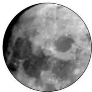
natural_image
Grayscale circular image of the Moon showing craters and maria (no text or symbols)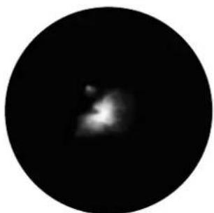
natural_image
Circular black image with a faint, blurry bright spot in the center (no text or symbols)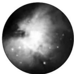
natural_image
Black-and-white astronomical image of a nebula or starburst structure with bright central glow and diffuse arms (no text or symbols)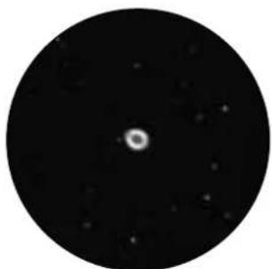
natural_image
Circular black-and-white astronomical image showing a bright central point surrounded by scattered stars (no text or symbols)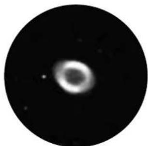
natural_image
Circular astronomical image showing a bright central object with diffuse surrounding glow, resembling a star or nebula (no text or symbols)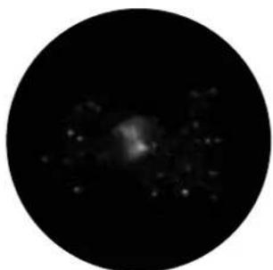
natural_image
Circular black-and-white astronomical image showing a diffuse bright source against a dark background, with scattered faint stars (no text or symbols)
natural_image
Circular grayscale astronomical image showing a star field with bright spots against a dark background (no text or symbols)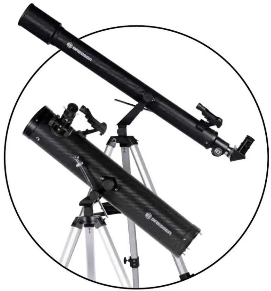
natural_image
Two black telescope-like instruments mounted on a tripod, enclosed in a circular frame (no text or symbols visible)
BRESSER®
Bresser GmbH
Gutenbergstr. 2 · DE-46414 Rhode Germany

- (FR) AVERTISSEMENT!
- About this Instruction Manual
- DANGER!
- ATTENTION!
- Intended Use
- General Warning
- RISK OF BLINDNESS!
- RISK OF CHOKING!
- FIRE RISK!
- Privacy PROTECTION!
- Accessories may vary depending on the model.
- All parts (Fig. 1-3)
- Part I - Construction
- General/Location
- NOTE!
- Tripod legs
- Mounting + tripod
- HINT:
- Accessory tray
- Tube
- Vertical fine adjustment
- Assembling the LED Viewfinder
- Viewfinder scope assembly:
- LED Viewfinder scope with Quick Insert
- Aligning the finder scope
- Protection-caps
- Inserting the eyepiece
- On refracting telescopes
- On reflecting telescopes
- Part II - Handling
- Mount
- Setup
- Vertical and horizontal adjustment
- Vertical adjustment
- Horizontal adjustment
- Observation
- Finding stars
- Accessories
- Eyepieces
- Formula for calculating magnification:
- Zenith mirror (refraction telescope only)
- Barlow lens
- Assembling and using refracting telescopes
- Assembling and using reflecting telescopes
- Smartphone holder
- Dismantling
- NOTES on cleaning
- Part III - Appendix
- Possible observation targets
- The moon (Fig. 24)
- Constellation Orion: The great Orion nebula / M 42 (Fig. 25)
- Constellation Lyra: The Ring Nebula / M 57 (Fig. 26)
- Constellation Vulpecula (little fox):
- The Dumbbell Nebula / M 27 (Fig. 27)
- DISPOSAL
- Downloads:
- BESCHERMING van privacy!
- BRESSER®
Brand : BRESSER
Model : STELLAR 60800 AZ
Category : Telescope