
Helium Pro - Wheelchair Quickie - Free user manual and instructions
Find the device manual for free Helium Pro Quickie in PDF.

| Product type | Folding manual wheelchair |
| Brand | Quickie |
| Model | Helium Pro |
| Total weight | From 6.4 kg |
| Maximum load | 120 kg (Helium) / 125 kg (Helium Pro) |
| Total width | 620 mm to 760 mm |
| Total length | Approximately 91 cm (with footrests) |
| Total height | Approximately 112 cm (high backrest) |
| Useful seat width | 320 mm to 460 mm |
| Useful seat depth | 340 mm to 480 mm |
| Front seat height | 430 mm to 550 mm |
| Backrest tilt angle | 59° to 105° |
| Backrest height | 250 mm to 450 mm |
| Rear wheels | 24" or 25" with quick-release axles |
| Front wheels | 3" to 6" with adjustable fork |
| Brakes | Immobilization brakes with lever (acting on tires), compact brake and unilateral brake as option |
| Suspension | Adjustable 4-Link rear suspension |
| Included accessories | Adjustable push handles, footrests, clothing guard, anti-tip wheels (depending on version) |
| Options | Under-belly belt, cane holder, handbike, adjustable armrests, Snoll On |
| Materials | Aluminum (frame, fork), steel (axles, anchor points), plastic (handles, front wheels), polyester PVC fabric |
| Standards | ISO 7176-8 (resistance), CE (directive 93/42/EEC), ISO 9001, ISO 13485, ISO 14001 |
| Warranty | 24 months (parts), 5 years (frame and cross brace) |
| Maintenance | Check tire pressure every 4 weeks; grease quick-release axles every 8 weeks; dealer inspection every 6 months |
| Cleaning | Mild household cleaner; disinfection with DGHM-listed product before transfer |
Frequently Asked Questions - Helium Pro Quickie
User questions about Helium Pro Quickie
0 question about this device. Answer the ones you know or ask your own.
Ask a new question about this device
Download the instructions for your Wheelchair in PDF format for free! Find your manual Helium Pro - Quickie and take your electronic device back in hand. On this page are published all the documents necessary for the use of your device. Helium Pro by Quickie.
USER MANUAL Helium Pro Quickie
- Push handles
- Backrest upholstery
- Sideguard
- Seat sling
- Footrest
- Castors
- Footboard
- Fork
- Quick-release axle
10.Wheel locks - Handrim
- Rear wheel

Area of application 7
1.0 General safety notes and driving limits 8
2.0 Handling 10
3.0 Transporting the chair 10
4.0 Options 10
Step Tubes 10
Brakes 10
Link Rear Suspension 11
Hand-Bike Axle Adjustment 13
Helium Pro Axle Adjustment 13
Footplate Adjustment 13
Seat 14
Options - Snoll on 14
Castors 14
Wheel alignment 14
Backrest 15
Sideguard 16
Push Handles 17
Anti-Tip Tubes 17
Crutch holder 18
Lap belt 18
5.0 Tyres and Mounting 19
6.0 Maintenance and care 19
7.0 Disposal / Recycling of materials 20
8.0Trouble-shooting 20
9.0 Transportability 21
10.0 Nameplate 23
11.0 Guarantee 23
12.0 Technical Data 24
13.0 Torque 27
Definitions
3.1 Definitions of words used in this manual
| Word Definition | |
| DANGER! | Advice to the user of Potential Risk of serious injury or death if the advice is not followed |
| WARNING! | Advice to the user of a potential risk of injury if the advice is not followed |
| CAUTION! | Advice to user that potential damage to equipment may occur if the advice is not followed |
| NOTE: General advice or best practice | |
| i | Reference To Additional Documentation |
NOTE:
The wheelchairs shown and described in this user guide may not correspond in every detail exactly to your own model. However, all instructions are completely relevant, regardless of possible detail differences.
The manufacturer reserves the right to alter without notice any weights, measurements or other technical data shown in this manual. All figures, measurements and capacities shown in this manual are approximate, and do not constitute specifications.
NOTE:
Please keep a note of your local service agent's address and telephone number in the space provided.
In the event of a breakdown, contact them and try to give all relevant details so they can help you quickly.
Dealer signature and stamp
Foreword
Dear Customer,
We are very pleased that you have decided in favour of a high-quality SUNRISE MEDICAL product.
This Owner's manual will provide numerous tips and ideas so that your new wheelchair can become a trustworthy and reliable partner in your life.
For Sunrise Medical, it is very important that we have a good relationship with our customers. We like to keep you up-to-date about new and current developments at our company. Keeping close to our customers means: fast service, as little red tape as possible, working closely with customers. When you need replacement parts or accessories, or if you just have a question about your wheelchair – we are there for you.
We want you to be satisfied with our products and service. At Sunrise Medical we are constantly working to develop our products further. For this reason, changes can occur in our palette of products with regard to form, technology, and equipment. Consequently, no claims can be construed from the data or pictures contained in this Owner's manual.

The management system of SUNRISE MEDICAL is certified to EN ISO 9001, ISO 13485 and ISO 14001.
As the manufacturer, SUNRISE MEDICAL, declares that the lightweight wheelchairs conform to the 93/42/ EEC / 2007/47/EEC guideline.
Please contact your local, authorised SUNRISE MEDICAL dealer if you have any questions regarding the use, maintenance or safety of your wheelchair.
In case there is no authorised dealer in your area or you have any questions, contact Sunrise Medical either in writing or by telephone.
Use
Wheelchairs are exclusively for a user who is unable to walk or has limited mobility, for their own personal use in and outdoor.
The maximum weight limit (includes the user and any weight of accessories fitted to the wheelchair) is marked on the serial number label, which is affixed to the Axle Tube below the seat.
Warranty can only be taken on if the product is used under the specified conditions and for the intended purposes.
The expected life of the wheelchair is 5 years. Please DO NOT use or fit any 3rd party components to the wheelchair unless they are officially approved by Sunrise Medical.
Area of application
The variety of fitting variants as well as the modular design mean that it can be used by those who cannot walk or have limited mobility because of:
- Paralysis
- Loss of extremity (leg amputation)
- Extremity defect deformity
Joint contractures/joint injuries - Illnesses such as heart and circulation deficiencies, disturbance of equilibrium or cachexia as well as for elderly people who still have strength in the upper body.
When considering provision, please also note the body size, weight, physical and psychological constitution, the age of the person, living conditions and environment.

IMPORTANT: DO NOT USE YOUR WHEELCHAIR UNTIL THIS MANUAL HAS BEEN READ AND UNDERSTOOD.
Sunrise Medical
Thorns Road
Brierley Hill
West Midlands
DY52LD
England
Phone: 0845 605 66 88
Fax: 0845 605 66 89
www.SunriseMedical.com
1.0 General safety notes and driving limits
The engineering and construction of this wheelchair has been designed to provide maximum safety. International safety standards currently in force have either been fulfilled or exceeded in parts. Nevertheless, users may put themselves at risk by improperly using their wheelchairs. For your own safety, the following rules must be strictly observed.
Unprofessional or erroneous changes or adjustments increase the risk of accident. As a wheelchair user, you are also part of the daily traffic on streets and pavements, just like anyone else. We would like to remind you that you are therefore also subject to any and all traffic laws. Be careful during your first ride in this wheelchair. Get to know your wheelchair.
Before each use, the following should be checked:
- Quick-release axles on the rear wheels
- Velcro on seats and backrests
- Tyres, tyre pressure and wheel locks.
Before changing any of the adjustments of this wheelchair, it is important to read the corresponding section of the user's manual.
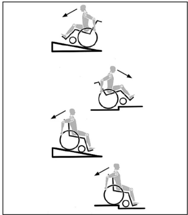
It is possible that potholes or uneven ground could cause this wheelchair to tip over, especially when riding uphill or downhill. When riding over a step or up an incline frontally, the body should be leaning forward.
DANGER!
NEVER exceed the maximum load of 125kg for driver plus any items carried on the wheelchair. If you exceed the maximum load, this can lead to damage to the chair, or you may fall or tip over, lose control and may lead to serious injury of the user and other people.
When it is dark, please wear light clothing or clothing with reflectors, so that you can be seen more easily. Make sure that the reflectors on the side and back of the wheelchair are clearly visible. We would also recommend that you fit an active light..
To avoid falls and dangerous situations, you should first practice using your new wheelchair on level ground with good visibility.
When getting on or off the wheelchair, do not use the footboards. These should be flipped up beforehand and swung to the outside as far as possible. Always position yourself as close as possible to the place where you wish to sit.
Only use your wheelchair properly. For example, avoid travelling against an obstacle without braking (step, kerb edge) or dropping down gaps.
The wheel locks are not intended to brake your wheelchair. They are only there to ensure that your wheelchair does not begin rolling unintentionally. When you stop on uneven ground, you should always use the wheel locks to prevent such rolling. Always apply both wheel locks; otherwise, your wheelchair could tip over.
Explore the effects of changing the centre of gravity on the behaviour of the wheelchair, for example on inclines, slopes, all gradients or when overcoming obstacles. Do this with the secure aid of a helper. With extreme settings (e.g. rear wheels in the most forward position) and less than perfect posture, the wheelchair may tip over even on a level surface. Lean your upper body further forward when going up slopes and steps.
Lean your upper body further back when going down slopes and steps. Never try to climb and descend a slope diagonally.
Avoid using an escalator which may lead to serious injury in the event of a fall.
Do not use the wheelchair on slopes >10^ . The Dynamic safe slope is dependant on the chair configuration, the users abilities and the style of riding. As the users abilities and style of riding cannot be pre-determined then the max safe slope cannot be determined. Therefore this must be determined by the user with the assistance of an attendant to prevent tipping. It is strongly recommended that inexperienced users have Ant-tips fitted. It is possible that potholes or uneven ground could cause this wheelchair to tip over, especially when riding uphill or downhill.
Do not use your wheelchair on muddy or icy ground. Do not use your wheelchair where pedestrians are not allowed.
- To avoid hand injuries do not grab in between the spokes or between the rear wheel and wheel lock when driving the wheelchair.
In particular when using lightweight metal handrims, fingers will easily become hot when braking from a high speed or on long inclines.
Only attempt stairs with the help of an attendant. There is equipment available to help you, e.g. climbing ramps or lifts, please use them. If there is no such equipment available, then the wheelchair must be tipped and pushed, never carried, over the steps (2 helpers). We recommend that users over 100kg in weight do not use this stairway manoeuvre!
In general, any anti-tip tubes fitted must be set beforehand, so that they cannot touch the steps, as otherwise this could lead to a serious tumble. Afterwards the anti-tip tubes must be set back to their correct position.
Make sure that the attendant only holds the wheelchair using securely mounted parts (e.g. not on the footrests or the sideguards).
When using the lifting ramp make sure that the anti-tip tubes fitted are positioned outside the danger area.
Secure your wheelchair on uneven ground or when - transferring (e.g. into a car) by using the brakes. If and whenever possible, during a journey in a - specially fitted vehicle for disabled people, vehicle occupants should use the seats in the vehicle and the appropriate restraint system. This is the only way to ensure that occupants will have the maximum protection if there is an accident. When using safety elements offered by SUNRISE MEDICAL and using a specially designed safety system, lightweight wheelchairs can be used as a seat when being transported in a specially fitted vehicle. (See the Chapter on "Transportation").
Depending on the diameter and setting of the castors, as well as the centre of gravity setting of the wheelchair, the castors may begin to wobble at high speeds. This can lead to the castors being blocked and the wheelchair may tip over. Therefore, please make sure that the castors are adjusted correctly (see the Chapter "Castors"). In particular, do not travel on an incline without brakes, travel at a reduced speed. We recommend that novice users use anti-tip tubes.
Anti-tip tubes should prevent the chair tipping over backwards unintentionally. Under no circumstances should they take the place of transit wheels, and be used to transport a person in a wheelchair with the rear wheels removed.
When reaching for objects (which are in front of, to the side or behind the wheelchair) make sure that you do not lean too far out of the wheelchair, as if you change the centre of gravity there is a risk of tipping or rolling over. The hanging of additional load (back pack or similar items) onto your chair backposts can affect the rearward stability of your chair, especially when used in combination with recliner backrests. This can cause the chair to tip backwards causing injury.
For thigh amputees you must use anti-tip tubes. Before setting off, check that your tyre pressure is correct. For rear wheels it should be at least 3.5 bar (350 kPa). The max. pressure is indicated on the tyre. The knee-lever brakes will only work if there is sufficient tyre pressure and if the correct setting has been made (see the Chapter on "Brakes"). If the seat and back sling are damaged, you must replace them immediately.
Be careful with fire, in particular with burning cigarettes. Seat and back slings can be set alight. If the wheelchair is subject to direct sunlight for a long period of time, then parts of the wheelchair (e.g. frame, legrests, brakes and sideguard) may become hot (>41^) .
Always make sure that the quick-release axles on the rear wheels are set properly and lock in. If the button on the quick-release axle is not pressed in, the rear wheel cannot be removed.
WARNING!
The effect of the knee-lever brake as well as the general driving characteristics are dependant on tyre pressure. The wheelchair is significantly lighter and easier to manoeuvre when the rear wheels are pumped up correctly and both wheels have the same pressure.
Make sure that your tyres have sufficient tread! Please note that you are subject to any and all traffic laws when driving in public traffic.
Always be careful with your fingers when working or adjusting the wheelchair!
The products shown and described in this manual may not be exactly the same in every detail as your own model. However, all instructions are still entirely relevant, irrespective of detail differences.
The manufacturer reserves the right to alter without notice any weights, measurements or other technical data shown in this manual. All figures, measurements and capacities shown in this manual are approximate and do not constitute specifications.
We at SUNRISE MEDICAL have been awarded the ISO 9001 Certificate, which affirms the quality of our pro ducts at every stage, from R & D to production. This product complies with the standards set forth in EU directives. Optional equipment and accessories are available at extra charge.
2.0 Handling
Quick-Release Axles On Rear Wheel
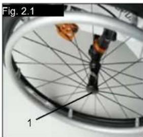
The rear wheels are equipped with quick-release axles. The wheels can, therefore, be installed or removed without using tools.
To remove a wheel, simply depress the quick-release button on the axle (1) and pull it out (Fig. 1).
CAUTION!
Hold the quick-release button on the axle depressed when inserting the axle into the frame to mount the rear wheels. Release the button to lock the wheel in place. The quick-release button should snap back to its original position
3.0 Transporting the chair
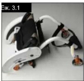
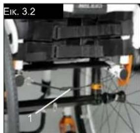
Transporting The Chair
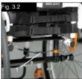
Removing the rear wheels will keep the chair as compact as possible. The backrest can be folded down by pulling the cord (1) (see picture 3) located on the backrest (Fig. 2 + 3).
4.0 Options
Step Tubes
Step Tubes
Step tubes are used by attendants to push a wheelchair over an obstacle. Simply step on the tube to push a wheelchair, for example, over a kerb or step.
WARNING!
Sunrise Medical strongly recommends the use of a step tube on any model where attendant use is the predominant intended use. Damage to the backposts may occur if you constantly use the backpost without a step tube, as a lever to pull back on to tip the wheelchair.
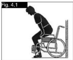
Getting into your wheelchair on your own
-
Push the wheelchair to a wall or a solid piece of furniture;
-
Apply the brakes;
- The user can lower themselves into the wheelchair;
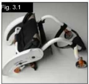
- Then position the feet in front of the heel straps (Fig. 4.1).
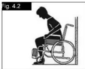
Getting out of your wheelchair on your own
- Apply the brakes;
- With one hand on the wheel or sideguard, the person should lean forwards slightly, to transfer the body weight to the front edge of the seat and then push up to an upright position with both feet firmly on the floor and one foot behind the other (Fig. 4.2).
Brakes
CAUTION!
Braking power can be affected by incorrect fitting and adjustment of the brakes, as well as tyre pressure which is too low.
Wheel locks
Your wheelchair is equipped with two wheel locks. They are applied directly against the tyres. To engage, press both brake levers forward against the stops. To release the locks, pull the levers back to their original positions.
Braking power will decrease with:
Worn tyre tread
Tyre pressure that is too low
Wet tyres
- Improperly adjusted wheel locks.
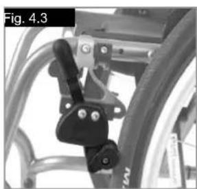
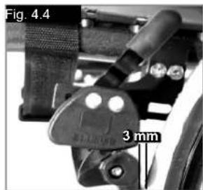
Brakes...
The wheel locks have not been designed to be used as brakes for a moving wheelchair. The wheel locks should therefore never be used to brake a moving wheelchair. Always use the hand-rims for braking. Make sure that the gap between the tyres and wheel locks complies with given specifications. To re-adjust, loosen the screw and set the appropriate gap. Then re-tighten the screw (Fig. 4.3 and 4.4).
CAUTION!
After each adjustment of the rear wheels, check the wheel lock gap and re-adjust if necessary.
Brake lever extension
The longer lever helps to minimise the effort needed to set the wheel locks.
The brake lever extension is screwed to the brakes. By raising this, it can be flipped forward (Fig. 4.5).
CAUTION!
Mounting the wheel lock too close towards the wheel will result in a higher effort to operate. This might cause the brake lever extension to break!
Leaning onto the brake lever extension while transferring will cause the lever to break! Splashing water from tyres might cause the wheel lock to malfunction.
CAUTION!
Incorrect mounting of the wheel lock will result in a higher effort to operate.
This might cause the wheel lock extension lever to break.
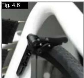
Compact brakes
Compact brakes are underneath the seat sling and are operated by pulling the brakes towards the rear, in the direction of the tyre. For the brakes to work properly, this must be pulled until it reaches the stops, (Fig.4.6).

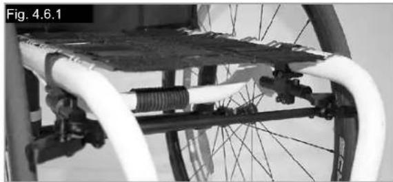
The One-arm Wheel Lock
The one arm wheel lock is underneath the seat sling and is operated by pulling the brake lever, which is located on the left or right side, towards the rear, in the direction of the tyre. For the brakes to work properly, this must be pulled until it reaches the stop, (Fig.4.6.1)
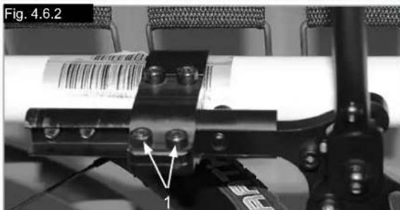
Adjustment
To adjust the brake, loose the screws (1) and mount the wheel lock where it will work in a proper way (Fig.4.6.2).
CAUTION!
Incorrect mounting of the one arm wheel lock can lead to serious injury of the user and other people.
Link Rear Suspension
WARNING!
Rear suspension can affect the stability of the wheelchair. To avoid a fall, use a spotter and/or anti-tips when becoming familiar with new equipment.
1. Tuning the 4-Link Rear Suspension
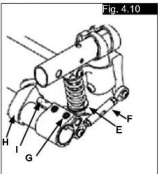
a. To stiffen the suspension, turn the spring preload adjustor (A) clockwise (looking up at the suspension system from underneath the wheelchair).
b. To soften the suspension, turn the spring preload adjustor (A) counter-clockwise (looking up at the suspension system from underneath the wheelchair)
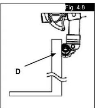
2. Alignment of Suspension Link Arms
Do not adjust the link arms (B, Fig.4.8). These are set at the factory to ensure proper tracking and performance of the 4-Link Rear Suspension system. (see next page).
Link Rear Suspension...
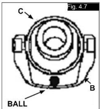
Setting the Toe to Zero
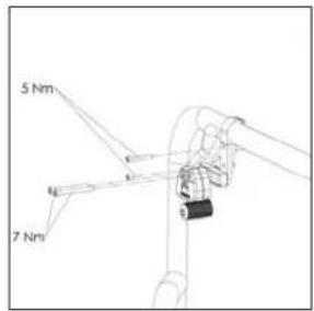
Loosen the cap screws (A) (3 per side, unless equipped with anti-tips then 4 per side) that secure the camber tube clamp. Observe the ball in the level (B), and rotate the camber tube (C) until the ball is centered in the level. The toe is now set at zero (Fig. 4.7, 4.8).
Before tightening the screws (A), make certain that the camber tube is centered left-to-right relative to the wheelchair frame, and the flat portions underneath outer camber tube clamp are parallel side to side. The end of the camber tube should be flush with the outer most portion of the camber tube clamp. Torque fasteners (A) to 62 in-lbs. (7 Nm).
Setting the Toe to Zero-Alternative Method
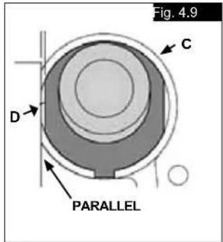
Place the entire wheelchair on a flat horizontal table or ground surface. Loosen the cap screws (A) (3 per side, unless equipped with anti-tips then 4 per side) that secure the camber tube clamp. Locate the flat surfaces on the front and rear of the camber plugs (D). Place an object that is known to have an accurate 90^ corner (such as a carpenters square, drafting triangle, etc.) down on the flat horizontal surface and up against the flat of the camber plug.
Rotate the camber tube and plug assembly until the flat surface of the camber plug is parallel to the measuring tool (Fig 4.7, 4.8, 4.9, 4.10). Before tightening the screws (A), make certain that the camber tube is centered left-to-right relative to the wheelchair frame and the flat portions underneath outer camber tube clamp are parallel side to side. The end of the camber tube should be flush with the outer most portion of the camber tube clamp. Torque the fasteners to 62 in-lbs. (7 Nm).

CAUTION!
When turning the 4-Link Rear Suspension, always make one change at time and write down the change. This takes patience, but allows you to understand how each change affects the ride of the wheelchair in conjunction with rear suspension.
NOTE- The lower shock mount is designed to have a loose feel, this is by design to allow for proper suspension travel.

CAUTION!
Never remove the barrel nut (C) that connects camber clamp to the shock camber clamp.
3. Maintenance
The maintenance requirements listed below should be followed along with general wheelchair maintenance called out in Section XI.
a. Do not apply lubrication to shock end bushings or coils. b. You can apply lubrication to the link ends after cleaning with a mild soap and soft
brush.
c. Use a soft brush to clear any dirt or debris from coil system.
d. Never use a high-powered washer for cleaning the 4-Link Rear Suspension.
Hand-Bike Axle Adjustment
Hand-Bike-Axle
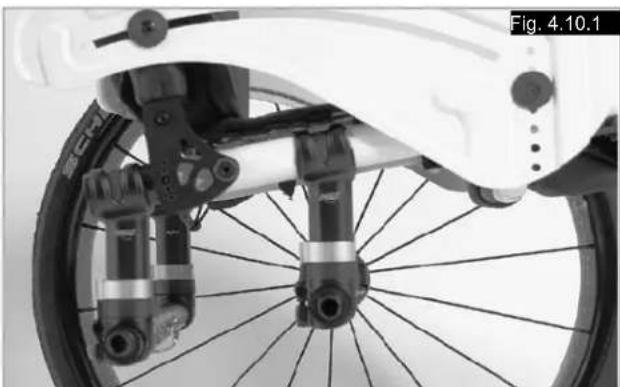
It is necessary to adjust the hand-bike axle to bias the centre of gravity rearwards. This allows safe use of a hand-bike accessory, (Fig.4.10.1).

DANGER!
Using a hand-bike without the hand-bike axle makes the wheelchair unstable and can lead to serious injury of the user and other people.
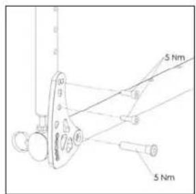
Helium Pro Axle Adjustment
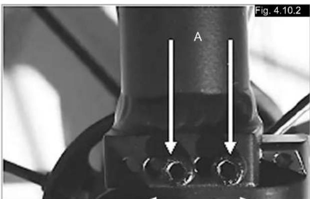
Helium Pro Axle Plate (C.O.G. Adjustment).
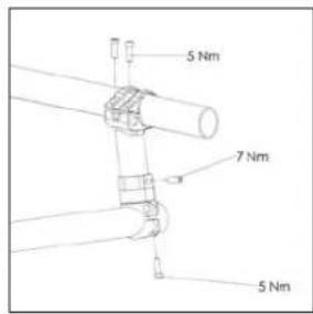
To adjust the center of gravity (COG) remove the 2 screws, (A) and move the bracket into preferred position, (Fig.4.10.2). refit and tighten the screws (5Nm)
Footplate Adjustment
Adjusting The Footrest

WARNING!
Do not stand on the footboard! Even if the user is sitting in the chair, there is still a risk of tipping over and injury. When transferring, do not stand on the footboard, there is a risk of tipping over and injury.
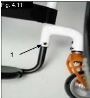
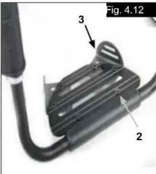
Releasing the screw (1) will allow you to adjust the footrest to correspond to the length of your lower leg and re-attach the footrest. The angle of the footrest may be individually adjusted by loosening screws (2). The side protection (3) on the footrest prevents the feet slipping off accidentally. Make sure that after any adjustment work, all screws are tightened correctly (see the page on torque) (Fig. 4.11 - 4.12).
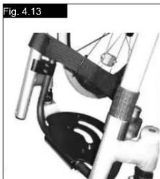
High-mount footrest
The high-mount footrest is fitted on the inner part of the frame and permits a higher footrest position (Fig. 4.13).
Seat
Adjusting The Seat Height
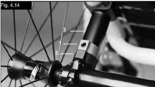
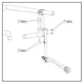
To adjust the rear seat height release the Allen screws (1) (one on each side), which fix the clamp to the axle stem (2). Remove the spacer bracket (3), to adjust the seat height +/- 1 cm. For large adjustments, reduce the length of the axle stem as required. Tighten the 2 Allen screws to 7 Nm. (Fig. 4.14).
NOTE:
An adjustment to the castor angle may be necessary when adjusting the rear seat height.
Seat sling
To tighten the upholstery, please use the straps below the upholstery.
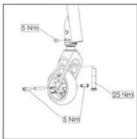
Adjusting the castor
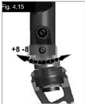
To ensure that both forks are set parallel, simply count the teeth visible on both sides. After setting the castor fork, the teeth will guarantee a secure position, allowing an adjustment of 16^ in 2^ increments. Use the flat side on the front of the castor fork to check for a right-angled position to the ground (Fig. 4.15).
The patented design allows the castor fork to be turned, so that it can be reset at right-angles to the ground when the seat angle is changed.
Setting the directional stability
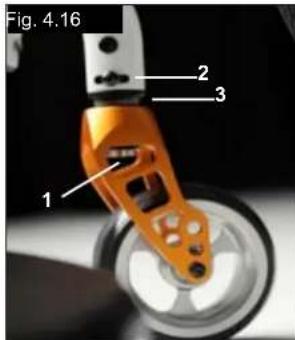
Release the Allen screws (1) on the underside of the fork. You can then undo the screw (2). You can now turn the black socket (3) left or right. Left - chair pulls to the left Right - chair pulls to the right Then tighten up the screw (2) again. Please set a 90^ angle from the fork to the floor. Now tighten up the screw (1) again. (Fig. 4.16).
Options - Snoll on

Please see the separate Owners' Manual for details of the Snoll On accessory.
Castors
Castor, Castor Adapter, Castor Fork
From time to time the wheelchair may veer slightly to the right or left, or the castors may flutter. This may be caused by the following:
- The forward or reverse wheel motion has not been set properly.
- The castor angle has not been adjusted properly.
- Castor and/or rear wheel air pressure is incorrect; wheels do not turn smoothly.
The optimum adjustment of the castors is required for the wheelchair to run in a straight line.
Castors should always be adjusted by an authorized dealer. The castor plates must be re-adjusted, and the wheel locks must be checked any time the rear wheel position has been altered.
Wheel alignment
Adjusting The Wheel Alignment
Important: To achieve the very best movement, the rear wheels must be adjusted to their optimum position, which means correctly adjusting the wheel alignment.
To do this, measure the distance between both wheels front and rear to ensure that they are parallel to one another.
The difference between both measurements should not exceed
5 mm.
To adjust the wheels to make them parallel, loosen the screws and turn the axle sleeve accordingly. Make sure that after any adjustment work, all screws are tightened correctly (see the page on torque).
HELIUM tracking adjustment
Setting the toe-in/toe-out to zero.
NOTE: A wheelchair with 0^ camber cylinders cannot have toe-in or toe-out. This setting is necessary only with 3^ and 6^ camber cylinders.
The term "toe-in or toe-out" defines how well the rear wheels of the chair are aligned in relation to the ground.
This determines how well the chair will run. Normal resistance or rolling resistance is present when toe-in is set to zero.
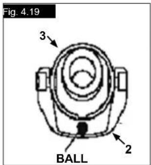
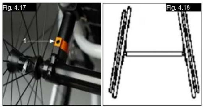
To set toe-in/toe-out to zero: loosen the Allen screws (1) (1 on each side), which secure the angle tube clamp. Check the ball in the horizontal (2) plane and turn the angle tube (3) until the ball is in the centre. Toe-in is now zero.
Before tightening the screws (1), check that the camber tube is centred left-to-right. The gap should be the same on both sides, or there should be no gap at all. Tighten the screws to 7 Nm. (Fig. 4.17 - 4.19).
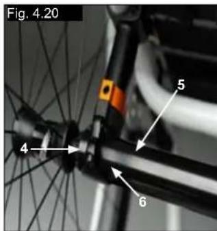
Adjusting the rear wheelbase width:
The rear wheelbase is defined as the distance between the upper side of the rear wheels and the backrest tubes, and is represented by factory setting (1.25cm) . This has to be increased if a larger gap between the tyres and the optional height-adjustable armrests has to be created (Fig. 4.20).
NOTE: When adjusting the rear wheelbase, adjust first one wheel then the other. If both sides are loosened at the same time, this will alter the toe-in/toe-out adjustment. To adjust the rear wheelbase, the parts of the camber (4) move telescopically into or out of the camber tube (5), and lock into place when they reach the end. Loosen screw (6) (located closest to the camber tube) on the left side of the chair. Move the quick-release axle inwards or outwards to achieve the desired wheelbase. Tighten the screws to 7 Nm. Repeat this procedure on the right side of the chair and adjust the gap so that it is the same amount as on the left side.

Backrest
Angle-Adjustable Back
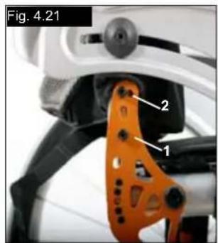
The backrest angle is adjusted by altering the position of the pin in the backrest mounting. The pin (1) must be completely clicked into place in the hole pattern on both sides, this gives you an angle adjustment of 8.5^ .
Fit the red plastic pins into the unused holes. To reach a smaller angle increment (3.5^) you open the allen key screw (2) and re-set the screw into the second hole. Please use the relevant torque force (see matrix) to tighten the screw (2).
This gives you 12^ change in the back angle. Then move the pin (1) in the opposite direction to the next hole, which gives you 12^ - 8^ = 3.5^ change. (Fig. 4.21)
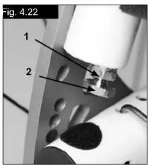
To reduce the play in the backrest, the nut (1) can be released, then the optimal position can be set using the set screw (2). Then re-tighten the nut (1). (Fig. 4.22).
CAUTION!
The screws must be re-tightened. Otherwise the angle adjustment will be lost.
Folding backrest
Release the backrest by pulling the cord. At the same time, push it forward to fold it down. To return the backrest to its original position, this must be pulled back as far as possible, until it locks into place on both sides.
CAUTION!
When folding the backrest down, please make sure that your fingers do not get caught.
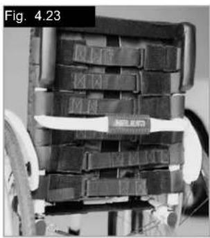
Adjustable back sling
The adjustable back sling can be adjusted for tension by using several straps.
The back sling upholstery can be accessed from the inside via an opening and can be padded to suit individual tastes (Fig. 4.23).
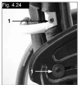
Height-adjustable backrest
The backrest may be set to various back heights, in 2.5 cm steps. The adjustment ranges are 25-30 cm, 30-35 cm, 35-40 cm and 40-45 cm. Release the screws (1+2) and set the backrest to the desired height. Tighten up the screws again (see the page on torque). (Fig. 4.24).
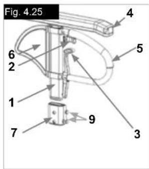
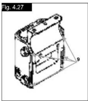
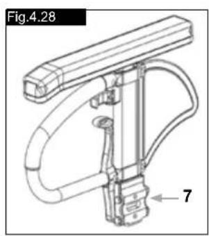
Armrest Receiver Attachment (Fig.4.25-4.28).
Adjusting Armrest Receiver Fit
To tighten or loosen the fit of the outer armpost in the receiver:
- Loosen the four receiver adjustment bolts (9) on the sides of the receiver.
- With the armrest in the receiver (7), squeeze the receiver to achieve the desired fit.
- Tighten the four bolts (9). (144 in-lbs, 16.3 Nm)
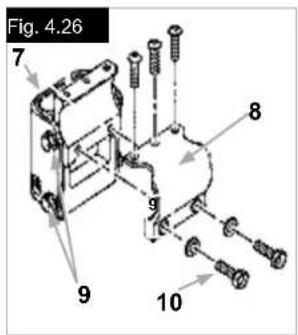
Position Adjustment
- Loosen the two clamp bolts (10) until clamp is loose.
- Slide armrest receiver to desired position.
- Tighten
Fig.4.25 - 4.28 Parts key
- Outer armpost
- Height Release Lever
- Release lever
- Armrest pad
- Transfer bar
- Side panel
- Receiver
8.Clamp - Receiver adjustment bolts
- Clamp bolts
Sideguard
Single Post Height-Adjustable Armrests
(Fig.4.25-4.28).
- Installation
a. Slide the outer armpost into the receiver mounted to the wheelchair frame.
b. The armrest will automatically lock into place.
- Height Adjustment
a. Rotate height release lever (2) to second stop.
b. Slide armrest pad up or down to desired height.
c. Return lever to locked position against arm post.
d. Push arm pad (4) until upper arm post locks firmly into place.
- Removing Armrest
a. Pull lever 3 and lift entire arm. - Replacing Armrest
a. Slide armrest back into receiver until arm latches in place.
Push Handles
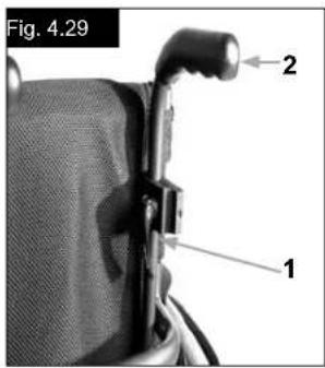
Height-Adjustable Push Handles
These handles are secured with pins to prevent them from sliding out unintentionally. Opening the quick-release lever (1) makes it possible to adjust the height of the push handles (2) to meet your individual needs. As you move the lever, you will hear a locking mechanism; you can now easily position the push handle as desired. The nut on the tension lever determines how tightly the push handles are clamped into place. If the nut is loose after adjusting the tension lever, the push handle will also be too loose. Turn the push handle from side to side before use to make sure that it is clamped securely enough into place. After adjusting the handle height, always clamp the tension lever (1) securely into place. If the lever is not secure, injuries could result when ascending stairs. (Fig. 4.29).
NOTE - If the height-adjustable push handles are not fitted properly, there is a risk that these will develop "play" or that they move out of position. Please make sure that the relevant screws are tightened correctly.
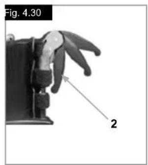
Fold-down push handles
If the push handles are not in use, they can be folded down depressing the button (2). When they are needed again, simply flip them back up until they click into place. (Fig. 4.30).
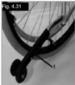
2. Adjusting the anti-tip tubes
To achieve the correct ground clearance of approx. 1" to 2" (2.5 cm to 5.0 cm), the anti-tip tubes must be raised or lowered.
Press the anti-tip tube release button, so that both release pins are drawn inwards. Move the inner tube up or down to slot into the height holes provided. Release the button. Fit the second anti-tip wheel in the same way. Both wheels should be at the same height. (Fig. 4.31).
DANGER!
Sunrise Medical Recommends Use Of Anti-Tip Tubes: If the anti-tip tubes are not fitted, or have been fitted incorrectly, there is a risk of tipping over and of injury.
Anti-Tip Tubes
WARNING
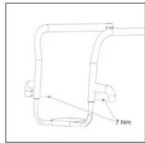
Sunrise Medical recommends anti-tip tubes for all chairs. When fitting anti-tip tubes, use a torque of 7 Nm.
1. Slotting the anti-tip tubes into the clamp:
a. Press the rear button on the anti-tip tube on the anti-tip tube adapter, so that both release pins are drawn inwards.
b. Slot the anti-tip tubes (1) into the anti-tip tube adapter.
c. Turn the anti-tip tubes downwards until the release pin locks into the clamp.
d. Fit the second anti-tip tube in the same way.
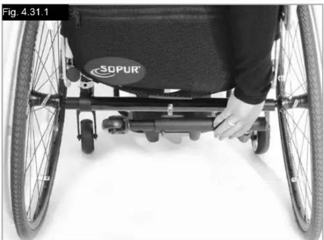
Active Anti Tip/Flip Up
The active Anti tip is mounted on the left or right side of the axle tube. By pushing it towards the axle tube, it can be flipped downwards for operation, (Fig.4.31.1).
WARNING!
Make sure that the anti tip will lock in the final position. An unlocked active anti tip can lead to serious injury of the user.
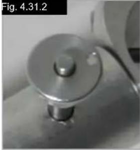
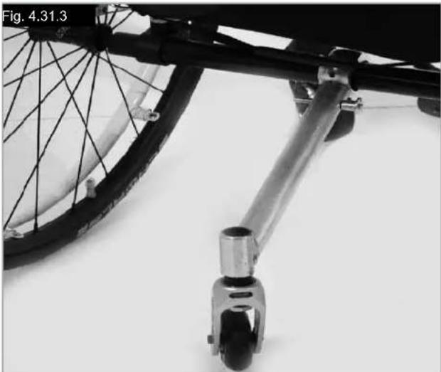
Anti-Tip Tubes...
Active Anti Tip For Sport
To remove the active anti tip for sport, press the button of the quick release pin and pull it out. Now pull out the tube from the anti tip receiver, (4.31.2 - 4.31.3).
Crutch holder
Crutch Holder
This device permits crutches to be transported directly on the wheelchair. It has a Velcro loop to fasten crutches or other aids.

CAUTION!
Never try to use or even remove the crutches or other aids while moving.
Lap belt
DANGER!
Before using your wheelchair ensure the lap belt is worn.
The lap belt must be checked on a dailybasis to ensure it is free from any obstruction or adverse wear.
Always make sure that the lap belt is correctly secured and adjusted prior to use. If the strap is too loose it could cause the user to slip down and risk suffocation or cause serious injury.
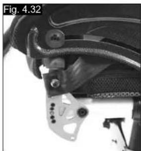
The lap belt is fitted to the wheelchair as shown in the illustrations. The seat belt comprises 2 halves. They are fitted using the existing seat stay retaining bolt fitted through the eyelet on the belt. The belt is routed under the rear of the side panel. (Fig. 4.32)
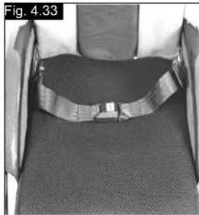
Adjust the belt position so buckles are in the centre of the seat. (Fig. 4.33)
Adjust lap belt to suit the user's needs as follows:
| To reduce the belt length | To increase the belt length |
| ← | ← |
| Feed free belt back through male buckle and slide adjusters. Ensure belt is not looped at male buckle. | Feed free belt through slide adjusters and male buckle to provide more belt length. |
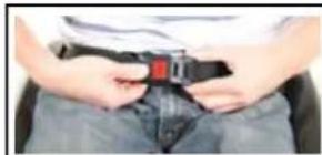
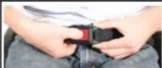
When fastened check space between the lap belt and user. When correctly adjusted it should not be possible to insert more than the flat of the hand between the lap belt and the user. (Fig. 4.34)
Lap belt...
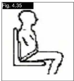
The lap belt should be fixed so that the belt sits at an angle of 45 degrees across the users pelvis. The user should be upright and be as far back as possible in the seat when correctly adjusted. The lap belt should not allow the user to slip down in the seat. (Fig. 4.35)

To fasten buckle: Firmly push male buckle into female buckle.
To release belt: Press exposed sides of male buckle and push towards centre whilst gently pulling apart.

WARNING!
If in doubt about the use and operation of the lap belt then ask your healthcare professional, wheelchair dealer, carer or attendant for assistance. The lap belt must only be fitted by an approved Sunrise Medical dealer / agent.
The lap belt should only be adjusted by a professional, or a Sunrise Medical approved dealer / agent.
The lap belt must be checked on a daily basis to ensure it is adjusted correctly and free from any obstruction or adverse wear.
Sunrise Medical does not encourage the transportation of any person in a vehicle using this lap belt as a method of restraint.

Please see Sunrise Medical transit booklet for further advice on transportation.
Maintenance:
Check lap belt, and securing components, at regular intervals for any sign of frays or damage. Replace if necessary.

WARNING
The lap belt should be adjusted to suit the end user as detailed above. Sunrise Medical recommend that the length and fit of the belt be checked on a regular basis to reduce the risk of the end user inadvertently re-adjusting the belt to an excessive length.
5.0 Tyres and Mounting
Solid rubber tyres are standard.
With pneumatic tyres always make sure that the tyres have the correct air pressure, as otherwise the performance of the wheelchair may be affected. If the tyre pressure is too low, rolling resistance will increase, requiring more effort to move the chair forward. Low tyre pressure also has a negative impact on manoeuvrability. If the tyre pressure is too high, the tyre could burst. The correct pressure for a given tyre is printed on the surface of the tyre itself.
Tyres are mounted the same way as an ordinary bicycle tyre. Before installing a new inner tube, you should always make sure that the base of the rim and the interior of the tyre are free of foreign objects. Check the pressure after mounting or repairing a tyre. It is critical to your safety and to the wheelchair's performance that regulation air pressure be maintained and that tyres be in good condition.
6.0 Maintenance and care
- Check the tyre pressure every 4 weeks. Check all tyres for wear and damage.
- Check the brakes approximately every 4 weeks to make sure that they are working properly and are easy to use.
- Change tyres as you would an ordinary bicycle tyre.
- All of the joints that are critical to using your wheelchair safely are self-locking nuts. Please check every three months to make sure that all bolts are secure (see the section on torque). Safety nuts should only be used once and should be replaced after use.
- Please use only mild household cleansers when your wheelchair is dirty. Use only soap and water when cleaning the seat upholstery.
6.0 Maintenance and care...
If your wheelchair should ever get wet, please dry it afterwards.
- A small amount of sewing-machine oil should be applied to quick-release axles approximately every 8 weeks. Depending on the frequency and type of use, we recommend taking your wheelchair to your authorised dealer every 6 months to have it inspected by trained personnel.
CAUTION!
Sand and sea water (or salt in the winter) can damage the bearings of the front and rear wheels. Clean the wheelchair thoroughly after exposure.
The following parts can be removed and sent back to the manufacturer/dealer for repair:
Rear wheels
Armrest
- Footrest holder
- Anti-Tip tubes
These components are available as spare parts. For further
information, please see the spare parts catalogue.
Hygiene measures when being re-used:
Prior to the wheelchair being re-used, it must be carefully prepared. All surfaces which come into contact with the user must be treated with a disinfection spray.
To do this, you must use a disinfectant from the DGHM list, e.g. Antifect Liquid (Schulke & Mayr) for rapid alcohol-based disinfection for medical products and medical devices, which must be disinfected quickly. Please take into account the manufacturer's instructions for the disinfectant you are using.
In general, a complete disinfection cannot be guaranteed on seams. We therefore recommend that you dispose of seat and back slings to avoid microbacterial contamination with active agents according to § 6 infection protection law.
7.0 Disposal / Recycling of materials
If the wheelchair has been made available to you free of charge, then it does not belong to you. If it is no longer required, then follow the instructions to return it as given by the organisation that made the wheelchair available to you.
In the following section, there is a description of the materials used on the wheelchair, in view of the disposal or recycling of the wheelchair and its packaging.
Particular regulations with regard to disposal or recycling may be in force locally and these must be taken into account when performing disposal. (This can include the cleaning or decontamination of the wheelchair prior to disposal).
Aluminium: Castor forks, wheels, sideguards for the chassis, armrest frame, footrest, push handles
Steel: Fixing points, quick-release axle
Plastic: Handles, tube stoppers, castors, footplates, armpads and 12" wheel/tyre
Packaging: Plastic bags made of soft polyethylene, cardboard
Upholstery: Woven polyester with PVC coatings and expanded combustion modified foam.
Disposal or recycling should be carried out by a disposal company or at a public disposal point. You can also return your wheelchair to your dealer for disposal.

8.0 Trouble-shooting
Wheelchair pulls to one side
- Check tyre pressure
- Check to make sure wheel turns easily (bearings, axle)
- Check the castor angle
- Check to make sure both castors are making proper contact with the ground
Castors begin to wobble
- Check the castor angle
- Check to make sure all bolts are secure; tighten if necessary (see the section on torque)
- Check to make sure both castors are making proper contact with the ground
Wheelchair / Cross-tube assembly does not snap into position in the seat saddle
- Chair is still new, i.e., the seat or backrest upholstery is still very stiff. This will improve with time.
Wheelchair is difficult to fold up
- Adjustable backrest upholstery is too stiff. Loosen it accordingly.
Wheelchair squeaks and rattles
- Check to make sure all bolts are secure; tighten if
necessary (see the section on torque) - Apply small amount of lubrication to spots where movable parts come into contact with one another
Wheelchair begins to wobble
- Check angle at which castors are set
Check tyre pressure - Check to see if rear wheels are adjusted differently
9.0 Transportability
DANGER!
There is a risk of serious injury or death if this if this advice is ignored!
Transportation of your wheelchair within a vehicle:
A wheelchair secured in a vehicle will not provide the equivalent level of safety and security as a vehicle seating system. It is always recommended that the user transfers to the vehicle seating. It is recognised that this is not always practical for the user to be transferred and in these circumstances, where the user must be transported whilst in the wheelchair, the following advice must be followed:
DANGER!
Confirm that your chair is crashest suitable (see nameplate or crashest bracket at the rear of the chair (Fig.1)
Confirm that the vehicle is suitably equipped to transport a passenger in a wheelchair, and ensure the method of access/egress is suitable for your wheelchair type. The vehicle should have the floor strength to take the combined weight of the user, the wheel chair and accessories.
Sufficient space should be available around the wheelchair to enable clear access to attach, tighten and release the wheelchair and occupant tie down restraints and safety belts.
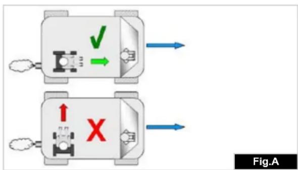
The occupied wheelchair must be located in a forward facing position and secured by the wheelchair tie down and occupant restraint straps (WTORS tie downs meeting the requirements of ISO 10542 or SAE J2249) in accordance with the WTORS manufacturer's instructions.
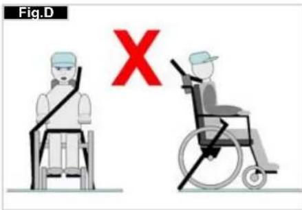
The wheelchair's use in other positions within a vehicle has not been tested e.g. transportation in a side facing position must not be carried out under any circumstances (Fig. A).
The wheelchair should be secured by a Tie Down Restraint system, conforming to ISO 10542 or SAE J2249 with non-adjustable front straps and adjustable rear straps, which typically use Karabiner clips/S hooks and tongue and buckle fittings. These restraints generally comprise of 4 individual straps that are attached to each corner of the wheelchair.
The tie-down restraints should be fitted to the main • frame of the wheelchair as indicated in the diagram on the following page, and not to any attachments or accessories, e.g. not around the spokes of wheels, brakes or footrests.
The tie-down restraints should be attached as close as possible at an angle of 45 degrees and tightened securely in accordance with the manufacturer's instructions.
Alterations or substitutions must not be made to the wheelchair securement points or to structural and frame or components without consulting the manufacturer.
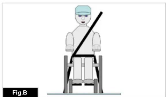
Failure to do so will invalidate the ability of a Sunrise Medical wheelchair to be transported within a vehicle. Both pelvic and upper torso restraint belts must be used to restrain the occupant to reduce the possibility of head and chest impacts with the vehicle components and serious risk of injury to the user and other vehicle occupants. (Fig B) The upper torso restraint belt should be mounted to the vehicle "B" pillar - failure to do so will increase the risk of serious abdominal injuries to the user.
A head restraint suitable for transportation (see label on - headrest) must be fitted and suitably positioned at all times during transportation.
Postural supports (lap straps, lap belts) should not be used or relied on for occupant restraint in a moving vehicle unless they are labelled as meeting the requirements specified in ISO 7176-19:2001 or SAE J2249.
The safety of the user during transportation depends upon the diligence of the person securing the tie-down restraints and they should have received appropriate instructions and/or training in their use.
Wherever possible remove and stow safely away from the wheelchair all auxiliary equipment, for example:
Crutches, Loose cushions and Tray Tables.
- Articulating/elevating leg rest should not be used in the elevated position when the wheelchair and user are being transported and the wheelchair is restrained using Wheelchair Transport and Occupant Restraints.
- Reclining backrests should be returned to an upright position.
The manual brakes must be firmly applied.
- Restraints should be mounted to the vehicle "B" pillar and should not be held away from the body by wheelchair components such as armrest or wheels.
Transportability...
Occupant Restraints Instruction:
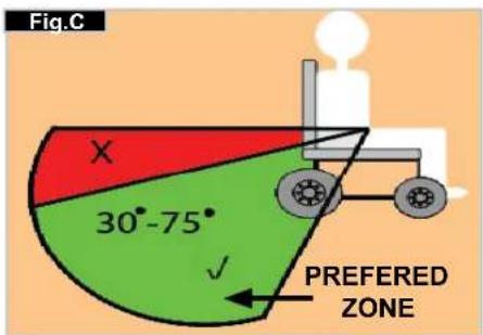
- The pelvic restraint belt must be worn low across the front of the pelvis so that the angle of the pelvic belt is within the preferred zone of 30 to 75 degrees to the horizontal.
A steeper (greater) angle within the preferred zone is desirable i.e. closer to, but never exceeding 75 degrees. (Fig C)
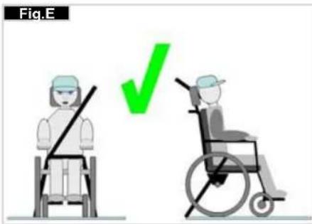
- The upper torso restraint belt must fit over the shoulder and across the chest as illustrated Fig d and e Restraint belts must be adjusted as tightly as possible consistent with user comfort.
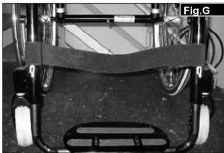
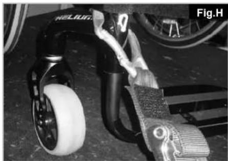
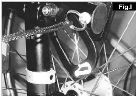
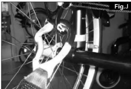
Restraint belt webbing must not be twisted when in use. The upper torso restraint belt must fit over the shoulder and across the shoulder as illustrated in Fig D and E. - The attachment points to the chair are the inner front side frame just above the castor, and the rear side frame. The straps are fitted around the side frames at the intersection of the horizontal and vertical frame tubes. (See Figs G-H-I)
- The tie down symbol (Fig F) on the wheelchair frame indicates the position of the wheelchair restraint straps. The straps are then tensioned after the front straps have been fitted to secure the wheelchair.
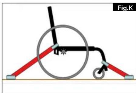
Positioning of wheelchair tie down restraints on wheelchair:
- Location of the front and rear tie down labels (Fig.G - H).
- Position of the front, (Fig.I) and rear, (Fig.J), wheelchair tie down restraint and the tie down label.
- Side view of tie down straps, (Fig.K).
10.0 Nameplate
Nameplate
The nameplate is located on either the cross-tube assembly or the transverse frame tube, as well as on a label in the owner's manual. The nameplate indicates the exact model designation and other technical specifications. Please provide the following pieces of information whenever you have to order replacement parts or to file a claim:
- Serial number
- Order number
Month/Year

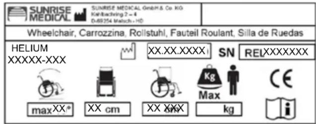
| HELIUM XXXXX-XXX | Product Name / Number of SKUs. |
| Maximum safe slope with anti-tipps fitted, Depends on wheelhair setting, posture and physical capabilities of the user. | |
| Seat width. | |
| XX cm | Depth (maximum). |
| XX cm | Load Maxmum. |
| Max | CE Mark |
| XXX kg | User's Guide. |
| Date of manufacture. | |
| SN RELXXXXXX | Serial number. |
11.0 Guarantee
Guarantee
THIS DOES NOT AFFECT YOUR LEGAL RIGHTS IN ANY WAY.
Guarantee conditions
1) Repair or replacement is carried out by the authorised Sunrise Medical dealer.
2) To fulfil the guarantee conditions, should servicing need to be carried out on your wheelchair under this agreement, contact the designated Sunrise Medical authorised dealer immediately, with precise details on the type of difficulty. Should you be using the wheelchair outside the area covered by the designated Sunrise Medical authorised dealer, the work will be carried out under "guarantee conditions" by another dealer as designated by the manufacturer.
3) Should a part or parts of the wheelchair require repair or replacement within 24 months (5 years for frame and cross-brace) after transfer of ownership to the original purchaser, and provided that this person is still the owner of the wheelchair as a result of a specific manufacturing or material defect, the part or parts will be repaired or replaced free of charge, if the wheelchair is returned to the authorised Sunrise Medical dealer.
Note: This guarantee cannot be transferred.
4) The guarantee also covers all repaired or replaced parts for the remaining period of the guarantee for the wheelchair.
5) For spare parts which are fitted after the start of the original guarantee, we give a further 24-month guarantee.
6) Consumable parts are normally excluded from the guarantee, except in the case that premature wear of the part is the direct result of a manufacturing fault. These parts include, amongst others, upholstery, tyres, inner tubes and similar parts.
7) The guarantee conditions above cover all product parts for models which were purchased at full sales price.
8) Normally we do not accept responsibility if a repair or replacement of the wheelchair is required for one of the following reasons:
a) The product or part has not been maintained or serviced in accordance with the manufacturer's recommendations as shown in the User Instructions and/or the Service Instructions. Accessories have been used which are not specified as original accessories.
b) The wheelchair or a part of the wheelchair was damaged through neglect, accident or improper use.
c) Alterations to the wheelchair or parts, which are not in accordance with the manufacturer's specifications or the carrying out of repairs before informing the authorised dealer.
12.0 Technical Data
Overall width:
With standard 25" wheels, including handrails with 6^ camber: SW + 30cm
Overall length: 91 cm with SD 48
Overall height: 112 cm with BH 45
Weight in kg: from 6.4kg
Maximum load:
Helium 120kg
Seat heights:
The choice of frames, forks and castors, as well as the rear wheel size (24", 25") determines the seat heights which can be achieved.
| Norm min. | max. Norm min. | max. | |||||
| Overall length with footrest | 770 mm 1050 | mm Seat surface | angle | 0° 15° | |||
| Overall width 620 mm 760 mm | Effective seat | depth | 340 mm 480 mm | ||||
| Folded length N/A N/A Effective seat | width | 320 mm 460 mm | |||||
| Folded width N/A N/A Seat height at | the front edge | 430 mm 550 mm | |||||
| Folded height | N/A | N/A | Backrest angle | 59° | 105° | ||
| Total weight | 6.4 kg | 13.0 kg | Back height | 250 mm | 450 mm | ||
| Weight of the heaviest individual part | - | 2.1 kg with 24" rear wheel | Distance from the footrest to the seat | 220 mm 520 mm | |||
| Static stability - downhill | 10° | 10° Angle from leg | to seat | 92° | 100° | ||
| Static stability - uphill (with anti-tip tube) | 10° | 10° Distance from | the armrest to the seat | N/A N/A | |||
| Static stability - sideways | 10° | 10° Front position | of the armrests | N/A N/A | |||
| Dynamic stability - uphill Power consumption | N/A N/A Handrim | diameter | 540 mm 567 mm | ||||
| Overcoming obstacles | N/A N/A Horizontal axle | position | + 56 mm | + 11 mm | |||
The wheelchair conforms to the following standards:
a) Requirements and tests for static strength, impact resistance and fatigue strength (ISO 7176-8) Yes
b) Drive and control systems for power wheelchairs, requirements and test (ISO 7176-14) n.a.
c) Environmental test in accordance with ISO 7176-9 n.a.
d) Flammability resistance of upholstered parts in accordance with ISO 7176-16 (EN 1021-1/2) Yes
Technical Data >>
| Castor Fork Type of frame Front seat height | in cm | Rear seat height in cm | ||
| 3" | 98 mm x 32 mm | low | 43 43 - 30 | |
| 44 44 - 31 | ||||
| 45 45 - 32 | ||||
| high | 47 47 - 34 | |||
| 48 48 - 35 | ||||
| 49 49 - 36 | ||||
| 111 mm x 32 mm | low | 44 44 - 31 | ||
| 45 45 - 32 | ||||
| 46 46 - 33 | ||||
| high | 48 48 - 35 | |||
| 49 49 - 36 | ||||
| 50 50 - 37 | ||||
| 4" | 98 mm x 32 mm | low | 44 44 - 31 | |
| 45 45 - 32 | ||||
| 46 46 - 33 | ||||
| high | 48 48 - 35 | |||
| 49 49 - 36 | ||||
| 50 50 - 37 | ||||
| 111 mm x 32 mm | low | 45 45 - 32 | ||
| 46 46 - 33 | ||||
| 47 47 - 34 | ||||
| high | 49 49 - 36 | |||
| 50 50 - 37 | ||||
| 51 51 - 38 | ||||
| 111 mm x 45 mm | low | 45 45 - 32 | ||
| 46 46 - 33 | ||||
| 47 47 - 34 | ||||
| high | 49 49 - 36 | |||
| 50 50 - 37 | ||||
| 51 51 - 38 | ||||
| 123 mm x 45 mm | low | 45 45 - 32 | ||
| 46 46 - 33 | ||||
| 47 47 - 34 | ||||
| 48 48 - 35 | ||||
| high | 49 49 - 36 | |||
| 50 50 - 37 | ||||
| 51 51 - 38 | ||||
| 52 52 - 37 | ||||
Technical Data ...
| Castor Fork Type of frame Front seat height | in cm | Rear seat height in cm | ||
| 5" | 98 mm x 32 mm | low | 46 46 - 33 | |
| 47 47 - 34 | ||||
| high | 50 50 - 37 | |||
| 51 51 - 38 | ||||
| 111 mm x 32 mm | low | 46 46 - 33 | ||
| 47 47 - 34 | ||||
| 48 48 - 35 | ||||
| high | 50 50 - 37 | |||
| 51 51 - 38 | ||||
| 52 52 - 39 | ||||
| 111 mm x 45 mm | low | 47 47 - 34 | ||
| 48 48 - 35 | ||||
| high 51 51 - | 38 | |||
| 52 52 - 39 | ||||
| 123 mm x 45 mm | low | 47 47 - 34 | ||
| 48 48 - 35 | ||||
| 49 49 - 36 | ||||
| 50 50 - 37 | ||||
| high | 51 51 - 38 | |||
| 52 52 - 39 | ||||
| 53 53 - 40 | ||||
| 54 54 - 41 | ||||
| 6" 123 mm | x 45 mm | low | 50 50 - 37 | |
| 51 51 - 38 | ||||
| high | 54 54 - 41 | |||
| 55 55 - 42 | ||||
13.0 Torque
Torque.
NOTE: Wherever torque settings are specified, it is strongly recommended that a torque meter (not included), is used to verify correct torque specification is achieved. If no other information is given, the generic torque for M6 screws is 7 Nm.
Sommaire
Sommaire 28
Définitions 28
Avant-propos 29
Utilisation 29
Chere cliente, cher client,
Roulettes anti-bascule

AVERTISSEMENT!
Sunrise Medical S.r.l.
Via Riva, 20
Montale
29122
Piacenza
Italia
Tel: 0523 573111
Fax: 0523 570060
www.SunriseMedical.com
Sunrise Medical S.L.
Poligono Bakiola, 41
48498 Arrankudiaga - Vizcaya
Espana
Tel.: +34 (0) 902142434
Fax: +34 (0) 946481575
www.SunriseMedical.es
Aanpassing Helium Pro as 145
Sunrise Medical B.V.
Groningenhaven 18-20
3433 PE NIEUWEGEIN
The Netherlands
T: +31 (0)30 - 60 82 100
F: +31 (0)30 - 60 55 880
E: info@sunrisemedical.nl
www.SunriseMedical.nl
Gebruik
Aanpassing Helium Pro as
Alternative - Snoll on

for at sikre at der/DDke findes forhindringer erer slitage.
9.0 Transport i fordon
FARA!
Av aapieoetouc Tiow toxouc, n Toluoova 0 npapeiveo ooo to duvato tio oumuayn. The backrest can be folded down by pulling the cord (1) (see picture 3) located on the backrest (Eik.2 + 3).
4.0 Eπλογες
Σωλνες πατήματος
Σωληνεισηπήματος
Oi oWAnve Tnmuoc Xpnooiotioovtai aTo Touc ouvOouc yia va aveBaouov Touc EumpoaOius Tpoxou ts avatnpiknc TlouPovac Tavw ato evaetio. AAtaTnote Tavw OTO wAnva Yia va avatpeyete Eaappa Tnv avatnpikn TlouPova, yia napadeiyua, Tavw ato eva Kpaotieo nokalotnti.
IPOEIOHSH!
H Sunrise Medical ouviota evtheta n xphon o wlnva
patnmuoc oe kaeo movteo ontou n xpion anto ouvodo
atotalei tvkupa tpoopicioeyn xphon. Mtopei va
tpokanthei baaon otous niaw otulouc eav xpnoipotoiite
ouvexw tov tiow otuloxwpi c owlva patnmuoc, w
moxylo yia va tpaabe TPOC ta TIOW KA i v yepveTe Tnv
aavatnpikn TLOUthetava.
IwS va kaioeTe movoi oac stnv avanpiKn TOnuOpoVa
Me TUTIKOUC TPOXOUC 25", TEPIIaIaIaIaIaIaIaIaIaIaIaIaIaIaIaIaIaIaIaIaIaIaIaIaIaIaIaIaIaIaIaIaIaIaIaIaIaIaIaIaIaIaIaIaIaIaIaIaIaIaIa Ieipoc e0alao 6^ : SW + 30 cm
Sunrise Medical S.L.
Poligono Bakiola, 41
48498 Arrankudiaga - Vizcaya
Espana
Tel.: +34 (0) 902142434
Fax: +34 (0) 946481575
www.SunriseMedica.com
Sunrise Medical A.G.
Lückhalde 14
3074 Murbei Bern
Switzerland
Tel.: +41 (0) 31-958-3838
Fax:+41031-958-3848
www.SunriseMedical.com
Sunrise Medical AS
Dynamiteien 14B
1400 SKI
Norway
Tel.: +47 (0) 66963800
Fax: +47 (0) 66963838
www.SunriseMedical.com
Sunrise Medical AB
Box 9232
400 95 Goteborg
Sweden
Tel: +46 (0)31 748 37 00
Fax:+460)317483737
www.SunriseMedical.com
Sunrise Medical B.V
Groningenhaven 18-20
3433 PE NIEUWEGEIN
The Netherlands
T: +31 (0)30 - 6082100
F: +31 (0)30 - 60 55 880
E: info@sunrisemedicaln
www.SunriseMedical.net
G2 A/S
Graham Bells Vej 21-23 A
8200 Arhus N
Denmark
Sunrise Medical Poland Sp. z o.o.
ul. Elektronowa 6,
94-103 Lódž
Polska
Telefon: +48 42 209 36 67
Fax: +48 42 209 35 23
E-mail: pl@sunrisemedical.de
Sunrise-Medical.pl

- Definitions
- NOTE:
- Foreword
- Use
- Area of application
- General safety notes and driving limits
- DANGER!
- WARNING!
- Handling
- Quick-Release Axles On Rear Wheel
- CAUTION!
- Transporting the chair
- Transporting The Chair
- Options
- Step Tubes
- Getting into your wheelchair on your own
- Getting out of your wheelchair on your own
- Brakes
- Wheel locks
- Braking power will decrease with:
- Brakes...
- Brake lever extension
- Compact brakes
- The One-arm Wheel Lock
- Adjustment
- CAUTION!
- Link Rear Suspension
- Tuning the 4-Link Rear Suspension
- Alignment of Suspension Link Arms
- Link Rear Suspension...
- Setting the Toe to Zero
- Setting the Toe to Zero-Alternative Method
- Maintenance
- Hand-Bike Axle Adjustment
- Hand-Bike-Axle
- Helium Pro Axle Adjustment
- Helium Pro Axle Plate (C.O.G. Adjustment).
- Footplate Adjustment
- Adjusting The Footrest
- High-mount footrest
- Seat
- Adjusting The Seat Height
- Seat sling
- Adjusting the castor
- Setting the directional stability
- Options - Snoll on
- Castors
- Castor, Castor Adapter, Castor Fork
- Wheel alignment
- Adjusting The Wheel Alignment
- HELIUM tracking adjustment
- Adjusting the rear wheelbase width:
- Backrest
- Angle-Adjustable Back
- Folding backrest
- Adjustable back sling
- Height-adjustable backrest
- Armrest Receiver Attachment (Fig.4.25-4.28).
- Position Adjustment
- Fig.4.25 - 4.28 Parts key
- Sideguard
- Single Post Height-Adjustable Armrests
- Push Handles
- Height-Adjustable Push Handles
- Fold-down push handles
- Adjusting the anti-tip tubes
- Anti-Tip Tubes
- WARNING
- Slotting the anti-tip tubes into the clamp:
- Active Anti Tip/Flip Up
- Anti-Tip Tubes...
- Active Anti Tip For Sport
- Crutch holder
- Lap belt
- Lap belt...
- Maintenance:
- Tyres and Mounting
- Maintenance and care
- Maintenance and care...
- Hygiene measures when being re-used:
- Disposal / Recycling of materials
- Trouble-shooting
- Wheelchair pulls to one side
- Castors begin to wobble
- Wheelchair / Cross-tube assembly does not snap into position in the seat saddle
- Wheelchair is difficult to fold up
- Wheelchair squeaks and rattles
- Wheelchair begins to wobble
- Transportability
- Transportation of your wheelchair within a vehicle:
- Transportability...
- Occupant Restraints Instruction:
- Positioning of wheelchair tie down restraints on wheelchair:
- Nameplate
- Nameplate
- Guarantee
- Guarantee
- Guarantee conditions
- Note: This guarantee cannot be transferred.
- Technical Data
- Overall width:
- Maximum load:
- Seat heights:
- Torque.
- Sommaire
- Roulettes anti-bascule
- AVERTISSEMENT!
- Gebruik
- Aanpassing Helium Pro as
- Alternative - Snoll on
- Transport i fordon
- FARA!
- Eπλογες
- Σωλνες πατήματος
- Σωληνεισηπήματος
- IPOEIOHSH!
- IwS va kaioeTe movoi oac stnv avanpiKn TOnuOpoVa
Brand : Quickie
Model : Helium Pro
Category : Wheelchair