USER MANUAL Argon Quickie
natural_image
Black JAYC motor in a wheelchair with visible seat and wheels (no text or symbols)
ARGON
Directions for use
-
Push handles
-
Backrest upholstery
-
Sideguard
-
Seat sling
-
Footrest
-
Castors
-
Footboard
-
Fork
-
Quick-release axle
-
Wheel locks
-
Handrim
-
Rear wheel

Carrozzina:
We are very happy that you have decided in favour of a high-quality product from SUNRISE MEDICAL.
This user's manual will provide numerous tips and ideas so that your new wheelchair can become a trustworthy and reliable partner in your life.
Maintaining close links with our customers is of great importance to us at Sunrise Medical. We would therefore like to keep you up-to-date with our new and current developments. Keeping close to our customers also means fast service when you need replacement parts or accessories, or just have a question about your wheelchair — and with as little red tape as possible.
We want you to be satisfied with our products and service. Sunrise Medical therefore constantly works at continuous development of its products. For this reason, changes can occur in our range of products with regard to shape, technology, and fittings. Consequently, no claims can be construed from the data or pictures contained in this user's manual.
SUNRISE MEDICAL has been awarded the ISO 9001 Certificate, which affirms the quality of our products at every

As the manufacturer, SUNRISE MEDICAL, declares that the lightweight wheelchairs conform to the 93/42/EEC / 2007/47/EEC guideline.
stage, from R & D to production.
Please contact your local, authorised SUNRISE MEDICAL dealer if you have any questions concerning the use, maintenance, or safety of your wheelchair.
In the case that there is no authorised dealer in your area or you have any questions, you can contact Sunrise Medical either in writing or by telephone (contacts are mentioned on the last page).
Sunrise Medical Ltd.
Sunrise Business Park
High Street, Wollaston
West Midlands DY8 4PS
England
Telephone: +44/1384-446622
Fax: +44/1384-446644
www.sunrisemedical.com

IMPORTANT:
DO NOT USE YOUR WHEELCHAIR UNTIL
THIS MANUAL HAS BEEN READ AND
UNDERSTOOD.
Table of contents
1.0 General safety notes and driving restrictions 6
2.0 Transportability 8
3.0 Handling 10
4.0 Transporting the chair 10
5.0 Step Tubes 10
6.0 Options 10
Wheel Locks 10
Suspension system 10
Footplate Adjustment 11
Castor 11
Seat 11
Castor 11
Seat height 12
Wheel Alignment 12
Back 13
Armrest 13
Backrest 14
Lap belt 14
Anti-Tip Tubes 15
Seat 15
Seat Depth 15
Crutch Holder 15
Travel Wheels 15
7.0 Tyres and Mounting 15
8.0 Nameplate 16
9.0 Maintenance and care 16
10.0 Disposal / Recycling of materials 16
11.0 Trouble-shooting 16
12.0 Technical Data 17
13.0 Guarantee 18
14.0 Torque (Fig.11.0) 18
Use
Wheelchairs are exclusively for a user who is unable to walk or has limited mobility, for their own personal use in- and outdoor. The maximum weight limit (includes the user and any weight of accessories fitted to the wheelchair) is marked on the serial number label, which is affixed to the crossbar or stabiliser bar below the seat.
Warranty can only be taken on if the product is used under the specified conditions and for the intended purposes.
The expected life of the wheelchair is 5 years.
Please DO NOT use or fit any 3rd party components to the wheelchair unless they are officially approved by Sunrise Medical.
Area of application
The variety of fitting variants as well as the modular design mean that it can be used by those who cannot walk or have limited mobility because of:
Paralysis•
Loss of extremity (leg amputation)•
Extremity defect deformity•
Joint contractures/joint injuries•
Illnesses such as heart and circulation deficiencies, • disturbance of equilibrium or cachexia.
as well as for elderly people who still have strength in the • upper body.
When considering provision, please also note the body size, weight, physical and psychological constitution, the age of the person, living conditions and environment.
1.0 General safety notes and driving restrictions
The engineering and construction of this wheelchair has been designed to provide maximum safety. International safety standards currently in force have either been fulfilled or exceeded in parts. Nevertheless, users may put themselves at risk by improperly using their wheelchairs. For your own safety, the following rules must be strictly observed.
Unprofessional or erroneous changes or adjustments increase the risk of accident. As a wheelchair user, you are also part of the daily traffic on streets and pavements, just like anyone else. We would like to remind you that you are therefore also subject to any and all traffic laws.
Be careful during your first ride in this wheelchair. Get to know your wheelchair.
Before each use, the following should be checked:
- Quick-release axles on the rear wheels
• Velcro on seats and backrests
- Tyres, tyre pressure and wheel locks.
Before changing any of the adjustments of this wheelchair, it is important to read the corresponding section of the user's manual.
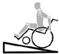
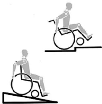
It is possible that potholes or uneven ground could cause this wheelchair to tip over, especially when riding uphill or downhill. When riding over a step or up an incline frontally, the body should be leaning forward.

DANGER!
NEVER exceed the maximum load of 120 kg for driver • plus any items carried on the wheelchair. If you exceed the maximum load, this can lead to damage to the chair, or you may fall or tip over, lose control and may lead to serious injury of the user and other people.
When it is dark, please wear light clothing or clothing with • reflectors, so that you can be seen more easily. Make sure that the reflectors on the side and back of the wheelchair are clearly visible. We would also recommend that you fit an active light.
To avoid falls and dangerous situations, you should first practice using your new wheelchair on level ground with good visibility.
When getting on or off the wheelchair, do not use the • footboards. These should be flipped up beforehand and swung to the outside as far as possible. Always position yourself as close as possible to the place where you wish to sit.
Only use your wheelchair properly. For example, avoid travelling against an obstacle without braking (step, kerb edge) or dropping down gaps.
The wheel locks are not intended to brake your wheelchair. • They are only there to ensure that your wheelchair does not begin rolling unintentionally. When you stop on uneven ground, you should always use the wheel locks to prevent such rolling. Always apply both wheel locks; otherwise, your wheelchair could tip over.
Explore the effects of changing the centre of gravity on • the behaviour of the wheelchair, for example on inclines, slopes, all gradients or when overcoming obstacles. Do this with the secure aid of a helper.
With extreme settings (e.g. rear wheels in the most forward • position) and less than perfect posture, the wheelchair may tip over even on a level surface.
Lean your upper body further forward when going up slopes • and steps.
natural_image
Two illustrations of a person in wheelchairs on stairs, showing different mobility behaviors (no text or symbols)
Lean your upper body further back when going down • slopes and steps. Never try to climb and descend a slope diagonally.
Avoid using an escalator which may lead to serious injury • in the event of a fall.
Do not use the wheelchair on slopes >10^ . The Dynamic safe slope is dependant on the chair configuration, the users abilities and the style of riding. As the users abilities and style of riding cannot be pre-determined then the max safe slope cannot be determined. Therefore this must be determined by the user with the assistance of an attendant to prevent tipping. It is strongly recommended that inexperienced users have Ant-tips fitted.
It is possible that potholes or uneven ground could cause this wheelchair to tip over, especially when riding uphill or downhill.
Do not use your wheelchair on muddy or icy ground. Do not use your wheelchair where pedestrians are not allowed.
To avoid hand injuries do not grab in between the spokes • or between the rear wheel and wheel lock when driving the wheelchair.
In particular when using lightweight metal handrims, fingers will easily become hot when braking from a high speed or on long inclines.
Only attempt stairs with the help of an attendant. There is equipment available to help you, e.g. climbing ramps or lifts, please use them. If there is no such equipment available, then the wheelchair must be tipped and pushed, never carried, over the steps (2 helpers). We recommend that users over 100 kg in weight do not use this stairway manoeuvre!
In general, any anti-tip tubes fitted must be set beforehand, so that they cannot touch the steps, as otherwise this could lead to a serious tumble. Afterwards the anti-tip tubes must be set back to their correct position.
Make sure that the attendant only holds the wheelchair • using securely mounted parts (e.g. not on the footrests or the sideguards).
When using the lifting ramp make sure that the anti-tip tubes fitted are positioned outside the danger area.
Secure your wheelchair on uneven ground or when transferring (e.g. into a car) by using the brakes.
If and whenever possible, during a journey in a specially fitted vehicle for disabled people, vehicle occupants should use the seats in the vehicle and the appropriate restraint system. This is the only way to ensure that occupants will have the maximum protection if there is an accident. When using safety elements offered by SUNRISE MEDICAL and using a specially designed safety system, lightweight wheelchairs can be used as a seat when being transported in a specially fitted vehicle. (See the Chapter on “Transportation”).
Depending on the diameter and setting of the castors, as well as the centre of gravity setting of the wheelchair, the castors may begin to wobble at high speeds. This can lead to the castors being blocked and the wheelchair may tip over. Therefore, please make sure that the castors are adjusted correctly (see the Chapter "Castors"). In particular, do not travel on an incline without brakes, travel at a reduced speed. We recommend that novice users use anti-tip tubes.
Anti-tip tubes should prevent the chair tipping over • backwards unintentionally. Under no circumstances should they take the place of transit wheels, and be used to transport a person in a wheelchair with the rear wheels removed.
When reaching for objects (which are in front of, to the side • or behind the wheelchair) make sure that you do not lean too far out of the wheelchair, as if you change the centre of gravity there is a risk of tipping or rolling over. The hanging of additional load (back pack or similar items) onto your chair backposts can affect the rearward stability of your chair, especially when used in combination with recliner backrests. This can cause the chair to tip backwards causing injury.
For thigh amputees you must use anti-tip tubes.
Before setting off, check that your tyre pressure is correct. For rear wheels it should be at least 3.5 bar (350 kPa). The max. pressure is indicated on the tyre. The knee-lever brakes will only work if there is sufficient tyre pressure and if the correct setting has been made (see the Chapter on "Brakes").
• If the seat and back sling are damaged, you must replace them immediately.
- Be careful with fire, in particular with burning cigarettes. Seat and back slings can be set alight.
- If the wheelchair is subject to direct sunlight for a long period of time, then parts of the wheelchair (e.g. frame, legrests, brakes and sideguard) may become hot (>41°C).
• Always make sure that the quick-release axles on the rear wheels are set properly and lock in. If the button on the quick-release axle is not pressed in, the rear wheel cannot be removed.
Note!
The effect of the knee-lever brake as well as the general driving characteristics are dependant on tyre pressure. The wheelchair is significantly lighter and easier to manoeuvre when the rear wheels are pumped up correctly and both wheels have the same pressure.
Note!
Make sure that your tyres have sufficient tread! Please note that you are subject to any and all traffic laws when driving in public traffic.
Note!
Always be careful with your fingers when working or adjusting the wheelchair!
The products shown and described in this manual may not be exactly the same in every detail as your own model. However, all instructions are still entirely relevant, irrespective of detail differences.
The manufacturer reserves the right to alter without notice any weights, measurements or other technical data shown in this manual. All figures, measurements and capacities shown in this manual are approximate and do not constitute specifications.
We at SUNRISE MEDICAL have been awarded the ISO 9001 Certificate, which affirms the quality of our products at every stage, from R & D to production. This product complies with the standards set forth in EU directives. Optional equipment and accessories are available at extra charge.
2.0 Transportability

DANGER!
There is a risk of serious injury or death if this if this advice is ignored!
Transportation of your wheelchair within a vehicle:
A wheelchair secured in a vehicle will not provide the equivalent level of safety and security as a vehicle seating system. It is always recommended that the user transfers to the vehicle seating. It is recognised that this is not always practical for the user to be transferred and in these circumstances, where the user must be transported whilst in the wheelchair, the following advice must be followed:
- Confirm that the vehicle is suitably equipped to transport a passenger in a wheelchair, and ensure the method of access/egress is suitable for your wheelchair type. The vehicle should have the floor strength to take the combined weight of the user, the wheel chair and accessories.
- Sufficient space should be available around the wheelchair to enable clear access to attach, tighten and release the wheelchair and occupant tie down restraints and safety belts.
- The occupied wheelchair must be located in a forward facing position and secured by the wheelchair tie down and occupant restraint straps (WTORS tie downs meeting the requirements of ISO 10542 or SAE J2249) in accordance with the WTORS manufacturer's instructions.
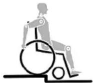
- The wheelchair's use in other positions within a vehicle has not been tested e.g. transportation in a side facing position must not be carried out under any circumstances (Fig. A).
- The wheelchair should be secured by a Tie Down Restraint system, conforming to ISO 10542 or SAE J2249 with non-adjustable front straps and adjustable rear straps, which typically use Karabiner clips/S hooks and tongue and buckle fittings. These restraints generally comprise of 4 individual straps that are attached to each corner of the wheelchair.
- The tie-down restraints should be fitted to the main frame of the wheelchair as indicated in the diagram on the following page, and not to any attachments or accessories, e.g. not around the spokes of wheels, brakes or footrests.
- The tie-down restraints should be attached as close as possible at an angle of 45 degrees and tightened securely in accordance with the manufacturer's instructions.
- Alterations or substitutions must not be made to the wheelchair securement points or to structural and frame or components without consulting the manufacturer. Failure to do so will invalidate the ability of a Sunrise Medical wheelchair to be transported within a vehicle.
- Both pelvic and upper torso restraint belts must be used to restrain the occupant to reduce the possibility of head and chest impacts with the vehicle components and serious risk of injury to the user and other vehicle occupants. (Fig B) The upper torso restraint belt should be mounted to the vehicle "B" pillar - failure to do so will increase the risk of serious abdominal injuries to the user.
- A head restraint suitable for transportation (see label on headrest) must be fitted and suitably positioned at all times during transportation.
- Postural supports (lap straps, lap belts) should not be used or relied on for occupant restraint in a moving vehicle unless they are labelled as meeting the requirements specified in ISO 7176-19:2001 or SAE J2249.
- The safety of the user during transportation depends upon the diligence of the person securing the tie-down restraints and they should have received appropriate instructions and/or training in their use.
- Wherever possible remove and stow safely away from the wheelchair all auxiliary equipment, for example: Crutches, Loose cushions and Tray Tables.
- Articulating/elevating leg rest should not be used in the elevated position when the wheelchair and user are being transported and the wheelchair is restrained using Wheelchair Transport and Occupant Restraints.
- Reclining backrests should be returned to an upright position.
- The manual brakes must be firmly applied.
- Restraints should be mounted to the vehicle "B" pillar and should not be held away from the body by wheelchair components such as armrest or wheels.

natural_image
Illustration of a person sitting on a chair with a diagonal bar, labeled Fig.B (no text or symbols on the figure itself)
Transportability >>>
Occupant Restraints Instruction:
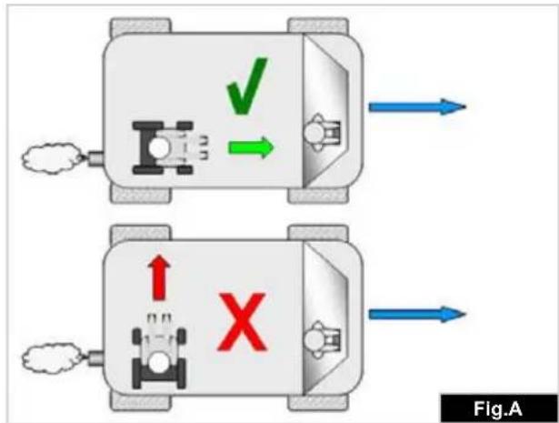
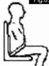
- The pelvic restraint belt must be worn low across the front of the pelvis so that the angle of the pelvic belt is within the preferred zone of 30 to 75 degrees to the horizontal. A steeper (greater) angle within the preferred zone is desirable i.e. closer to, but never exceeding 75 degrees. (Fig C)
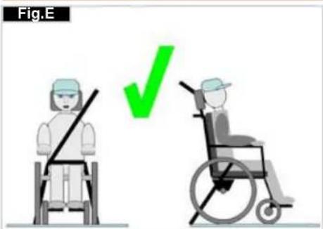
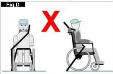
- The upper torso restraint belt must fit over the shoulder and across the chest as illustrated Fig d and e
Restraint belts must be adjusted as tightly as possible consistent with user comfort.
Restraint belt webbing must not be twisted when in use. The upper torso restraint belt must fit over the shoulder and across the shoulder as illustrated in Fig D and E.
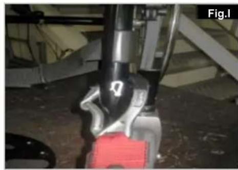
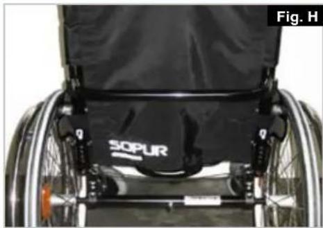
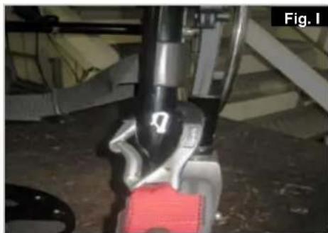
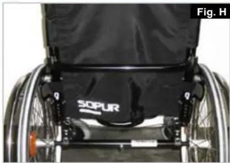
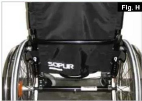
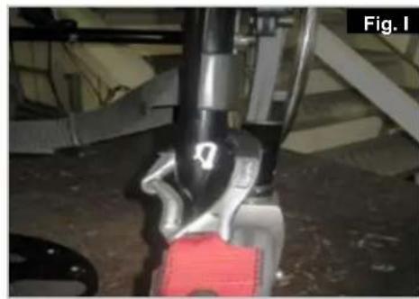
- The attachment points to the chair are the inner front side frame just above the castor, and the rear side frame. The straps are fitted around the side frames at the intersection of the horizontal and vertical frame tubes. (See Figs G-H-I)
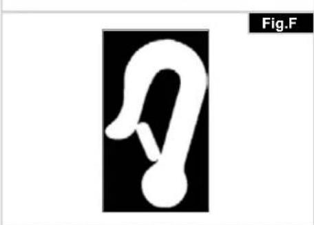
- The tie down symbol (Fig F) on the wheelchair frame indicates the position of the wheelchair restraint straps. The straps are then tensioned after the front straps have been fitted to secure the wheelchair.
natural_image
Pure graphical symbol of a stylized ear or loop without any text, numbers, or symbols
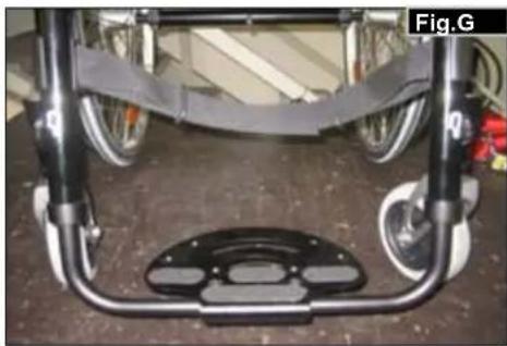
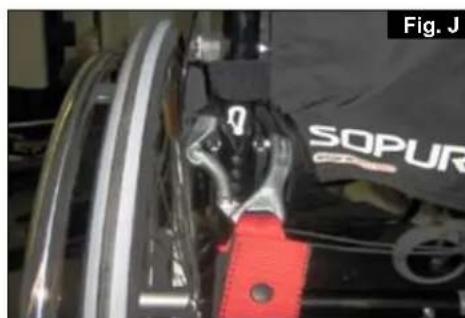
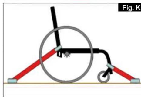
Positioning of wheelchair tie down restraints on wheelchair:
- Location of the front and rear tie down labels (Fig.G - H).
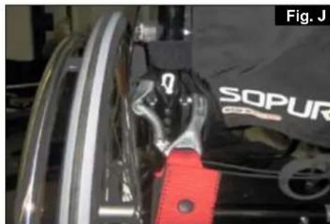
- Position of the front, (Fig.1) and rear, (Fig. J), wheelchair tie down restraint and the tie down label.
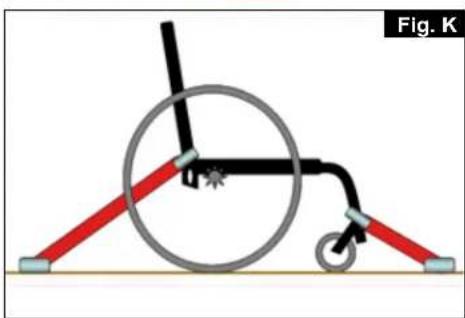
- Side view of tie down straps, (Fig.K).
natural_image
Front view of a bicycle chassis frame with visible wheels and structural brackets (no text or symbols)

natural_image
Close-up of a person in a wheelchair with visible SOPUR branding and mechanical components (no text or symbols on the device itself)
natural_image
Close-up of a robotic arm with visible joints and a red component, no text or symbols present

natural_image
Close-up of a mechanical component with red clamps and a black SOPUR logo (no readable text or symbols beyond branding)

natural_image
Diagram of a wheelchair mechanism with red and gray rods, no text or symbols present
3.0 Handling
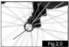
Quick-Release Axles for Rear Wheels (Fig.2.0)
The rear wheels are equipped with quick-release axles. The wheels can thus be installed or removed with out using tools. To remove a wheel, simply depress the quick-release button on the axle (1) and pull it out.
natural_image
Close-up of a bicycle wheel with visible spokes and hub, labeled Fig.2.0 (no text or symbols on the diagram itself)
CAUTION:
Hold the quick-release button on the axle depressed when inserting the axle into the frame to mount the rear wheels. Release the button to lock the wheel in place. The quick-release button should snap back to its original position.
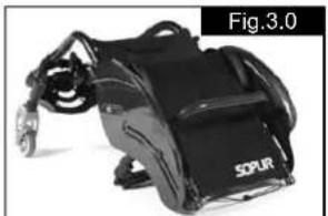
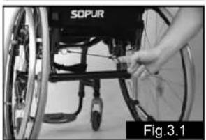
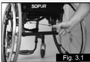
4.0 Transporting the chair
Transporting the chair (Fig.3.0-3.1)
Removing the rear wheels will keep the chair as compact as possible. The backrest can be folded down by pulling the cord located on the backrest.
natural_image
Black and white photo of a SOPUR motorcycle with visible suspension band (no text or symbols on device)
natural_image
Close-up of a hand adjusting a wheelbase component, labeled 'SOPUR' and 'Fig.3.1' (no other text or symbols visible)
5.0 Step Tubes
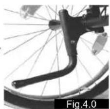
Step Tubes (Fig.4.0)
Step tubes are used by attendants to tip a wheelchair over an obstacle. Simply step on the tube to push a wheel chair, for example, over a kerb or step.
natural_image
Close-up of a bicycle wheel with visible spokes and a curved handle (no text or symbols)
NOTE: Sunrise Medical strongly recommends the use of a step tube on any model where attendant use is the
predominant intended use. Damage to the backposts may occur if you constantly use the backpost without a step tube, as a lever to pull back on to tip the wheelchair.
6.0 Options
Wheel Locks
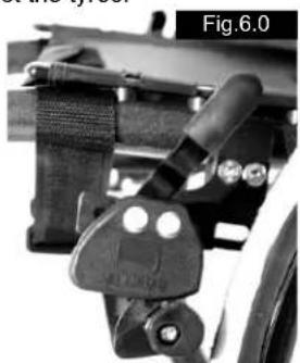
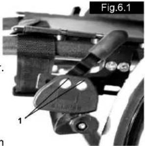
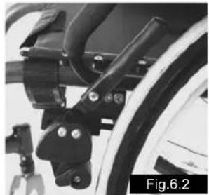
Wheel Locks (Fig. 6.0 - 6.2)
Your wheelchair is equipped with two wheel locks. They are applied directly against the tyres.
To engage, press both wheel-lock levers forward against the stops. To release the wheel, pull the levers back to their original positions.
Braking power will decrease with:
Worn tyre tread•
Tyre pressure that is too low•
Wet tyres•
Improperly adjusted wheel locks.
natural_image
Mechanical assembly component labeled Fig.6.0, showing clamping mechanism (no text or symbols on the diagram itself)
The wheel locks have not been designed to be used as brakes for a moving wheelchair. The wheel locks should therefore never be used to brake a moving wheel chair. Always use the handrims for braking. Make sure that the interval between the tyres and wheel locks complies with given specifications. To readjust, loosen screw (1) and set the appro priate interval. Tighten screw (see the page on torque)
natural_image
Close-up of a mechanical component with labeled parts, no readable text or symbols present
CAUTION:
After each adjustment of the rear wheels, check the interval to the wheel locks and readjust if necessary.
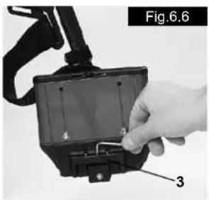
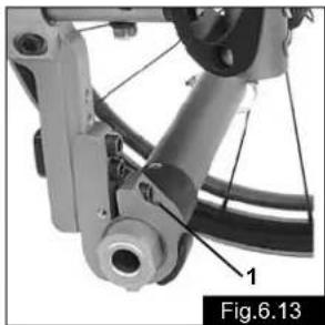
Extension for the wheel lock Lever (Fig.6.3)
The extension for the wheel lock lever can be removed or folded down. The longer lever helps to minimize the effort needed to set the wheel locks.
CAUTION:
Mounting the wheel lock too close toward the wheel will result in a higher effort to operate. This might cause the wheel lock extension lever to break!
natural_image
Close-up of a bicycle wheel assembly with mounting brackets and levers (no visible text or symbols)
Leaning onto the wheel lock extension lever while transferring will cause the lever to break! Splashing water from tyres might cause the wheel lock to malfunction.
Suspension system
Suspension system (Fig.6.3)
The function of the suspension system is determined by the buffer elements (1). Sunrise Medical offers a varied range of elements to suit the individual weight of the user.
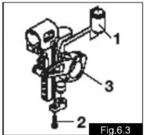
To replace the elements, remove the 2 screws (2) (1 on each side). Turn the rocker arms (3)
downwards; the buffer elements (1) can then be easily removed from the upper and lower openings.
To fit new sleeves, use the reverse procedure. Ensure that the buffer elements are securely located in the upper or lower openings.
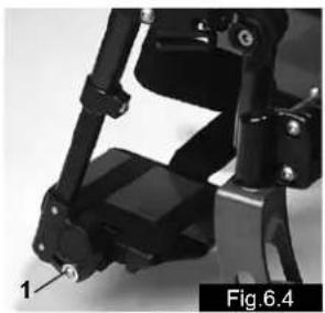
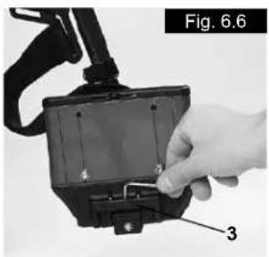
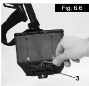
Footplates can be flipped up to facilitate getting in and getting out of your wheelchair.
They can also be tilted to six different angles relative to a level surface. Tighten screw (1) firmly on the outer side.
By removing the clips (2), the footplate can be adjusted to three different positions toward both the front and rear.
Loosen the adjustment screw (3) to change the horizontal position of the footplate. For this purpose, the footplate must be flipped up. When finished, make sure that all screws have been properly tightened (see the page on torque). A minimum interval of 2.5 centimeters from the ground should always be maintained.
natural_image
Close-up of a mechanical device with articulated joints and a labeled component (no readable text or symbols)

natural_image
Close-up of a hand using a tool to adjust or install a mechanical component, labeled 'Fig. 6.5' (no text on the object itself)
natural_image
Close-up of a hand inserting a component into a device housing (no visible text or symbols)
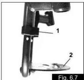
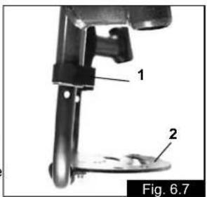
Removing screw (1) will allow you to adjust the footrest to correspond to the length of your lower leg. The angle of the footrest may be indi vi dual ly adjusted (not rigid foot rest) by loosening nuts (2). The footrest bracket (3) prevents feet from un inten tion ally slipping out place When finished, make sure that all screws have been properly tightened (see the page on torque).

Castor
Castors, Castor Plates, Forks
From time to time the wheelchair may veer slightly to the right or left, or the castors may flutter. This may be caused by the following:
Forward and/or reverse wheel motion has not been set • properly.
The castor angle has not been adjusted properly.
Castor and/or rear wheel air pressure is incorrect; wheels do not turn smoothly.
The wheelchair will not move in a straight line if the castors have not been properly ad justed. Castors should always be adjusted by an authorized dealer. The castor plates must be readjusted, and the wheel locks must be checked any time the rear wheel position has been altered.
Seat
Adjusting the seat height (Fig.6.8)
To adjust rear seat height, slacken and remove the 4 Torx screws (1) (2 each side) and the thread washer (2), which secures the clamp (3) for the camber tubes to the axle plates (4). Adjust the two camber tube clamps (3) to the required height and replace the 4 Torx screws. Before tightening the screws, please follow the instruction out to zero (See Fig.6.13 - 6.15). Tighten the screws to 7 Nm.
NOTE – An adjustment to the castor angle may be necessary when adjusting the rear seat height.
Castor
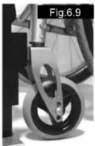
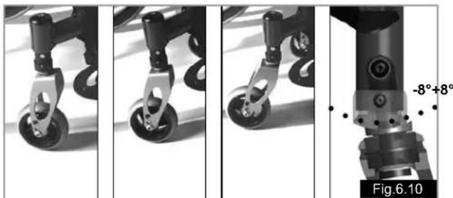
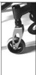
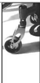
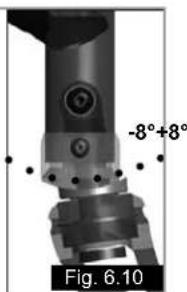
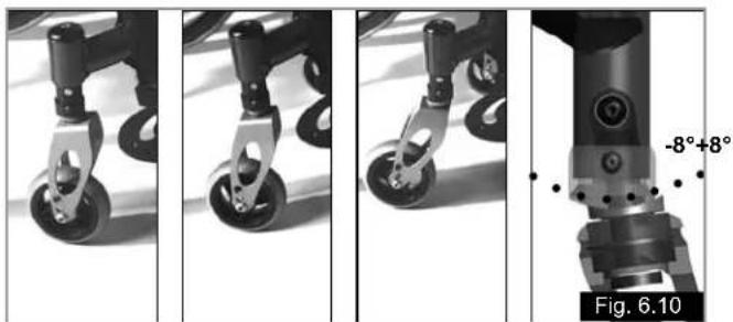
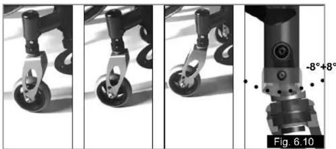
Adjusting the castor (Fig.6.9 - 6.10)
To ensure that both forks are set parallel, simply count the teeth visible on both sides.
After setting the castor fork, the teeth will guarantee a secure position, allowing an adjustment of 16^ in 2^ increments.
Use the flat side to check for a right-angled position to the ground.
The patented design allows the castor fork to be turned, so that it can be reset at right-angles to the ground when the seat angle is changed.
natural_image
Close-up of a bicycle's wheel and suspension mechanism (no text or symbols visible)
natural_image
Four-panel sequence showing mechanical components with wheels and a labeled angle of -8°+8°, no readable text or symbols beyond labels.
Seat height
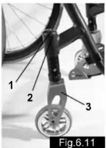
Adjusting front seat height (Adjustable frame, Fig.6.11)
- Slacken the screw (1) and remove the cover (2). This releases the height adjustment fixing.
-
By turning the castor connection you can continuously adjust the seat height by +/- 1.5 cm. Using the marking (3) on the castor connection, you can ensure that both castors are set the same.
-
Ensure that both castors are set at the same height, otherwise the chair cannot move in a straight line.
-
Ensure that the bolts (4) always face outwards and are at right-angles to the direction of travel, so that it will move in a straight line.
-
Replacing the cover (2) and tightening the screw (1) secures the height adjustment fixing. When doing this, be careful to observe the starting torque.
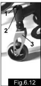
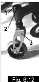
Adjusting the directional stability (Fig.6.12)
- Slacken the screw (1) and remove the cover (2). This releases the height adjustment fixing.
- Bring the castor fork at right-angles to the direction of travel and put a set-square onto the straight surface (3) of the fork.
- By turning the castor connection, the castor can be turned inwards or outwards to correct directional stability.
- Replacing the cover (2) and tightening the screw (1) secures the height adjustment fixing. When doing this, be careful to observe the starting torque.
Wheel Alignment
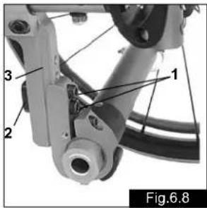
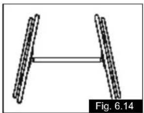
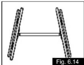
Adjusting Wheel Alignment (Fig.6.13 - 6.15)
Important: Your chair will only roll properly if the rear wheel positions have been opti mized, which means correctly adjusting the wheel alignment. To do this, measure [the distance between] both wheels front and rear to ensure that they are parallel to one another. The difference between both measurements should not exceed 5 mm. To adjust the wheels to make them paral lel, loosen the screws and turn the axle sleeve accordingly. When finished, make sure that all screws have been properly tightened (see the page on torque).
Argon tracking adjustment
- Setting the toe-in/toe-out to zero
NOTE: On a wheelchair with 0° camber cylinders it is not possible to set toe-in or toe-out. This setting is necessary only with 3°, 6° and 9° camber cylinders.
The term "toe-in or toe-out" defines how well the rear wheels of the chair are aligned in relation to the ground. This determines how well the chair will run. Normal resistance or rolling resistance is provided, when toe-in is set to zero.
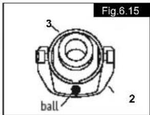
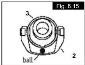
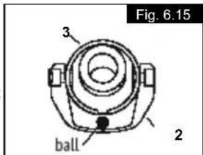
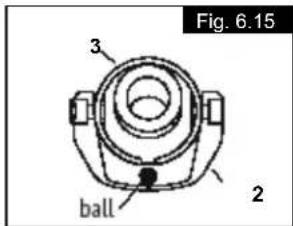
To set toe-in/toe-out to zero: Slacken the 2 screws (1) (1 each side) which secure the angle tube clamp. Check the ball in the horizontal (2) plane and turn the angle tube (3) until the ball is in the centre. Toe-in is now zero.
Before tightening screws (1), check that the camber tube is centred left-to-right. The gap should be the same on both sides, or there should be no gap at all. Tighten the screws to 7 Nm.
natural_image
Mechanical assembly diagram showing a linkage mechanism with labeled components (no readable text or symbols)

natural_image
Diagram of two parallel cylindrical objects with a horizontal double-headed arrow, labeled Fig.6.14 (no text or symbols on the objects themselves)
Width adjustment of the wheelbase
K. REAR WHEELBASE
The rear wheelbase is defined as the distance between the upper side of the rear wheels and the backrest tubes, and is represented by measurement X. The factory setting is (1.25 cm). A bigger gap is usually required when a sufficient gap between the tyres and optionally has to be created.
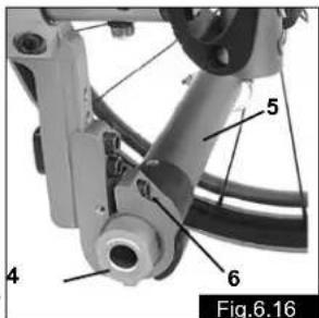
NOTE: When adjusting the rear wheelbase, adjust first one wheel then the other. If both sides are slackened at the same time, the adjustment of toe-in/toe-out will be altered.
To adjust the rear wheelbase, the parts of the camber (4) move telescopically into or out of the camber tube (5), and lock into place when they reach the end. Slacken screw (6) (located closest to the camber tube) on the left side of the chair. Move the quick-release axle inwards or outwards to achieve the desired wheel base. Tighten the screws to 7 Nm. Repeat this procedure on the right side of the chair and adjust the gap so that it is the same amount as on the left side.
Back
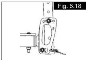
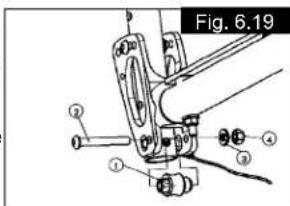
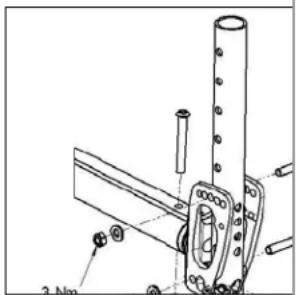
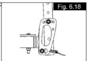
Angle adjustment of the folding backrest:
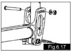
- Open the upper screws and loosen the screw connection (Fig.6.17).
- The hole in the back tube must be lined up with the hole in the connecting part, such that you can set the desired backrest angle (Fig.6.18).
- Fit the screw connection with the nut and washer until they are hand tight, so that there is no lateral play between the components. But you must still be able to fold the back tube down easily.
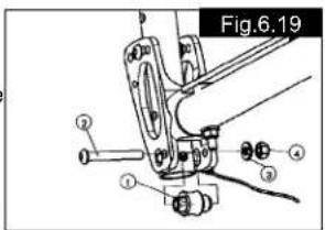
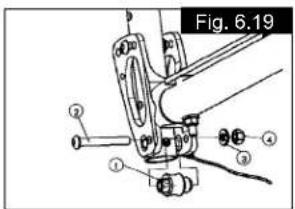
- Set the folding mechanism: To do this, loosen the nuts on the cam slightly (Fig.5.19). Set the cam (component 1) such that the folding mechanism locks into place with no play (if necessary use a 10 mm open-ended spanner to do this). Then hold the cam in position and tighten the nuts (5 Nm).
natural_image
Mechanical assembly diagram showing a linkage mechanism with no visible text or symbols

natural_image
Technical line drawing of a mechanical component with mounting bracket and base (no text or symbols)
- Repeat steps 1 to 4 for the second side.
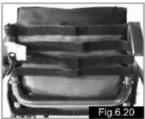
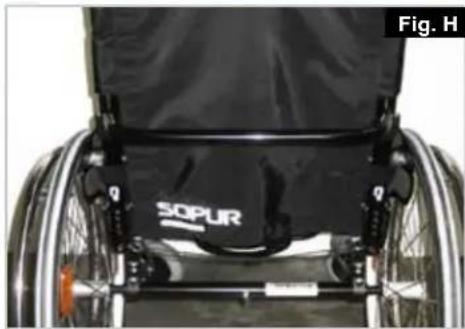
Adjustable back sling (Fig.6.20)
The adjustable back-sling can be adjusted for tension by using several straps.
The back-sling upholstery can be accessed from the inside via an opening and can be upholstered to suit individual tastes
natural_image
Close-up of a mechanical device with straps and a central body, labeled Fig.6.20 (no visible text or symbols on the device itself)
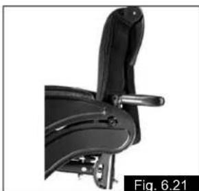
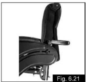
Height adjustable backrest (Fig.6.21)
The backrest height can be adjusted to 5 different positions (38–48 cm). Open and remove the bolt (1) and move the back tube into the desired position. Then fix the bolt again.

natural_image
Close-up of a black mechanical chair with handle and seat, labeled Fig.6.21 (no text or symbols on the chair itself)
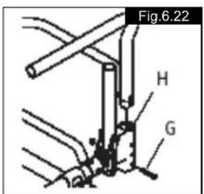
Standard sideguard, flip-up, removable with short or long arm pads
(Fig.6.22)
With the sideguard which is stepped down at the front it is possible to move up closer to a table. To flip them up press the lever (G) forwards, so that the sideguard is released.
ATTENTION!
Sideguards, and the armrests are not designed to be used to lift or carry the wheelchair.
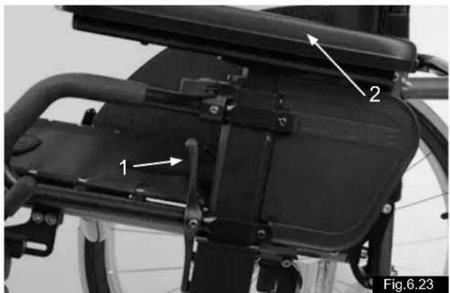
Sideguard, flip-up, removable with short or long arm pads, height-adjustable (Fig.6.23)
The arm pad can be height-adjusted in the following way. Pull the lever (1) and adjust the arm pad (2) to the desired height. Release the lever and push the arm pad (2) down until you hear it click into place.
ATTENTION!
Sideguards, and the armrests are not designed to be used to lift or carry the wheelchair.
Armrest
Quickie – height adjustable armrest
- Fitting
a. Push the outside armrest support into the clamp which is mounted on the chair frame.
b. The armrest will automatically lock into place.
- Height adjustment
a. Turn the release lever to the second position.
b. Push the arm support up or down to the required height.
c. Turn the release lever back to the armrest locking position.
d. Push the arm support in until the upper armrest locks into position.
- Removing the armrest
a. Turn the release lever to the first position and remove the armrest.
- Changing the armrest
a. Push the armrest back into the clamp.
b. Turn the release lever back to the armrest locking position.
- Adjusting the fit of the armrest receiver
To tighten or slacken the fit of the outside armrest in the clamp:
a. Release the four bolts on the sides of the clamp.
b. Hold the armrest in the clamp and squeeze the clamp together at the required fit.
c. Tighten up the four bolts.
- Adjusting the fit of the inner armrest
a. The outside armrest is fitted with two stud bolts.
b. Turn stud bolts in or out as required until you have found the desired fit.
natural_image
Close-up of a bicycle's back panel with labeled parts (1, 2), no visible text or symbols beyond labels
Backrest
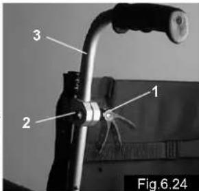
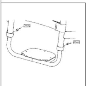
Height-Adjustable Push Handles (Fig.6.24)
These handles are secured with pins to prevent them from sliding out unintention ally. Opening the quick-release lever (1) makes it possible to adjust the push handles to meet your individual needs. As you move the lever, you will hear a locking mecha nism; you may now easily position the push handle as desired. The nut (2) on the tension lever determines how tightly the push handles are clamped into place. If the nut is loose after adjusting the tension lever, the push handle will also be too loose. Turn the push handle from side to side before use to make sure that it is clamped securely enough into place. After adjusting handle height, always clamp the tension lever (1) securely into place. If the lever is not secure, injuries could result when ascending stairs.
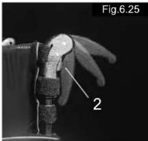
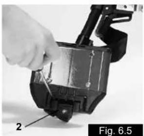
Fold-Down Push Handles
(Fig.6.25)
If the push handles are not in use, they can be folded down by depressing the button (2). When they are needed again, simply flip them back up until they click into place.
natural_image
Close-up of a robotic hand with a labeled component (2), no visible text or symbols beyond the label and number.
Lap belt
Before using your wheelchair ensure the lap belt is worn.
The lap belt must be checked on a daily basis to ensure it is free from any obstruction or adverse wear.
Always make sure that the lap belt is correctly secured and adjusted prior to use. Too loose a strap could cause the user to slip down and risk suffocation or cause serious injury.
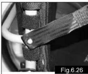
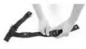
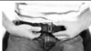
The lap belt is fitted to the wheelchair as shown in the illustrations. The seat belt comprises 2 halves. They are fitted using the existing seat stay retaining bolt fitted through the eyelet on the belt. The belt is routed under the rear of the side panel. (Fig.6.26)
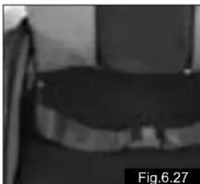
Adjust the belt position so buckles are in the centre of the seat. (Fig. 6.27)
natural_image
Close-up of a mechanical component with a textured grip and cable, labeled Fig.6.26 (no readable text or symbols)
natural_image
Grayscale photo of a dark, textured object with no visible text or symbols, labeled 'Fig.6.27' in the corner (no readable document text or symbols on the object itself)
Adjust lap belt to suit the user's needs as follows:
| To reduce the belt length | To increase the belt length |
 | 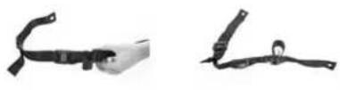 |
 |
| Feed free belt back through male buckle and slide adjusters. Ensure belt is not looped at male buckle. | Feed free belt through slide adjusters and male buckle to provide more belt length. Fig.6.28 |
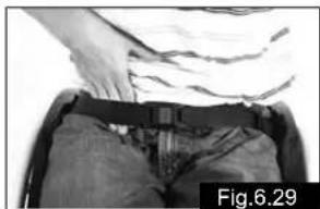
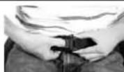
When fastened check space between the lap belt and user. When correctly adjusted it should
not be possible to insert more than
the fat of the hand between the lap belt and the user. (Fig.6.29)
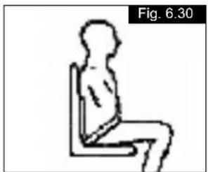
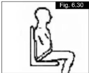
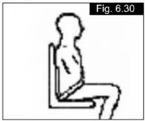
The lap belt should be fixed so that the belt sits at an angle of 45 degrees across the users pelvis. The user should be upright and be as far back as possible in the seat when correctly adjusted. The lap belt should not allow the user to slip down in the seat. (Fig.6.30)
natural_image
Person in a wheelchair wearing a belt and pants, with hands visible adjusting the seat (no text or symbols)
To fasten buckle:
Firmly push male buckle into
female buckle.
To release belt: Press exposed sides of male buckle and push towards centre whilst gently pulling apart. Fig 6.31
If in doubt about the use and operation of the lap belt then ask your healthcare professional, wheelchair dealer, carer or attendant for assistance.
Advice to client
The lap belt must only be fitted by an approved Sunrise Medical dealer / agent. The lap belt should only be adjusted by a professional, or a Sunrise Medical approved dealer / agent. The lap belt must be checked on a daily basis to ensure it is adjusted correctly and free from any obstruction or adverse wear.
Sunrise Medical does not encourage the transportation of any person in a vehicle using this lap belt as a method of restraint. Please see Sunrise Medical transit booklet for further advice on transportation.
Maintenance:
Check lap belt, and securing components, at regular intervals for
any sign of frays or damage. Replace if necessary.
NOTE:
The lap belt should be adjusted to suit the end user as detailed above. Sunrise Medical recommend that the length and fit of the belt be checked on a regular basis to reduce the risk of the end user inadvertently re-adjusting the belt to an excessive length.
Anti-Tip Tubes
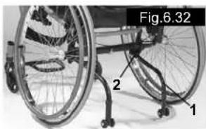
Quickie/Argon anti-tip tubes (Fig.6.32)
Sunrise Medical recommends anti-tip tubes for all chairs. When fitting anti-tip tubes, use a torque of 12 Nm.
natural_image
Close-up of a wheelchair with labeled parts (1, 2, Fig.6.32), no readable text or symbols beyond labels
- Slotting the anti-tip tubes into the clamp
a. Press the rear button on the anti-tip tube, so that both release pins are drawn inwards.
b. Slot the anti-tip tubes (1) into the anti-tip tube adapter (2).
c. Turn the anti-tip tubes downwards until the release pin locks into the clamp.
d. Fit the second anti-tip tube in the same way.
- Adjusting the anti-tip tubes (Fig.6.32)
To achieve the correct ground clearance of approx. 1" to 2" (3.5 cm to 5.0 cm), the anti-tip tubes must be raised or lowered. Press the anti-tip tube release button, so that both release pins are drawn inwards. Move the inner tube up or down to slot into the height holes provided. Release the button. Fit the second anti-tip wheel in the same way. Both wheels should be at the same height.
! WARNING!
Incorrect setup of the anti-tips, will increase the risk of a rearwards tip. You must swing the anti-tips upwards when going up or down large obstacles, (such as kerbs), to prevent them touching the ground. Rotate them back into position for normal use.
Seat
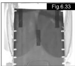
Seat sling
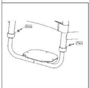
Remove the screws on the left side of the sling. Adjust the VELCRO® material to increase the tension of the seat sling. Tighten up the screws again.
natural_image
Medical X-ray image showing internal anatomical structures with no visible text or symbols
If the screws are difficult to fit back in place, try and locate the holes with a sharp object. Ensure also that the plastic base is in the corrected screws are tightened again.
Seat Depth
Seat depth growth (Optional) (Fig.6.34)
Using the optional cylinder for an offset seal, the backrest tubes can be moved either 1" (2.5 cm) or 2" (5 cm) further back than with the special seat cylinder.
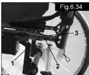
- Before fitting, establish which back system (rigid back) is to be used and which seat offset is required.
- If a seat depth increase of approx. 1" (2.5 cm) is required, screw (1) is screwed into hole 1.
- If a seat depth increase of approx. 2" (5 cm) is required, screw (1) is screwed into hole 2.
Crutch Holder
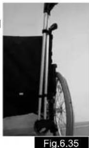
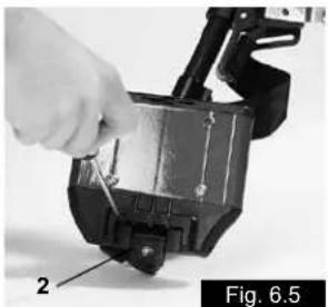
Crutch Holder (Fig.6.35)
This device permits crutches to be transported directly on a wheelchair. It has a Velcro loop (1) to fasten crutches or other aids.
CAUTION:
Never try to use or even remove the crutches or other aids while moving.
natural_image
Black-and-white photo of a wheelchair bicycle with visible suspension and wheel (no text or symbols)
Travel Wheels
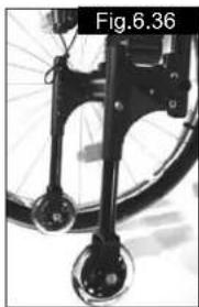
Travel Wheels (Fig.6.36)
Travel wheels should be used wherever your wheelchair would be too wide if the rear wheels were used (e.g., in airplanes, buses, etc.). After the rear wheels have been removed with the aid of the quick-release axles, the transit wheels can immediately be used to continue riding. The transit wheels are mounted so that they are approx. 3 centimeters above the ground when not in use. They are thus out of the way when riding, transporting, or when tipping to pass over obstacles (e.g., kerbs, steps, etc.).
natural_image
Close-up of a bicycle wheel and suspension mechanism (no text or symbols visible)
CAUTION:
Your wheelchair does not have any wheel locks when the transit wheels are being used.
NOTE: When the chair is to be set up with the transit wheels and the anti-tip tubes, the transit mounting must be installed between the camber tube clamp and the anti-tip tube clamp mounting (not shown).
7.0 Tyres and Mounting
Tyres and Mounting
Always make sure you that you maintain the correct tyre pressure, as this can have an effect on wheelchair performance. If the tyre pressure is too low, rolling resistance will increase, requiring more effort to move the chair for ward. Low tyre pressure also has a negative impact on maneuverability. If the tyre pressure is too high, the tyre could burst.
The correct pressure for a given tyre is printed on the surface of the tyre itself.
Tyres can be mounted the same way as an ordinary bicycle tyre. Before installing a new inner tube, you should always make sure that the base of the rim and the interior of the tyre are free of foreign objects. Check the pressure after mounting or re pairing a tyre. It is critical to your safety and to the wheelchair's performance that regulation air pressure be maintained and that tyres be in good condition.
8.0 Namepltersicht
Nameplate
The nameplate is located on either the cross-tube assembly for a folding wheelchair, or the transverse frame tube for a ridgid wheelchair, as well as on a label on the back page of the Users Manual. The nameplate indicates the exact model designation and other technical specifications.
Please provide the following pieces of information whenever you have to order replacement parts or to file a claim:
- Serial number
- Order number
- Month/Year
9.0 Maintenance and care
Safety Check
As the user you will be the first person to notice any possible defects. We therefore recommend that before each use, you check the following:
that the tyre pressure is correct.
that the brakes work correctly.
that all removable parts are securely fastened (e.g. armrests, footrest hangers, quick-release axles ...).
if there is any damage/defect, please contact your authorised dealer.
Maintenance
Check the tyre pressure at regular intervals.
Check all tyres for wear and damage at regular intervals, at least annually. Change the tyres as soon as there is any sign of damage or wear.
Check the seat and back sling for wear and damage at regular intervals, at least annually. Change these items as soon as there is any sign of damage or wear.
Check all frame and backrest components for wear and damage at regular intervals, at least annually. Change these items as soon as there is any sign of damage or wear.
Check the brakes for wear and damage at regular intervals, at least annually. Check that they are working properly and are easy to use. Change the brakes as soon as there is any sign of damage or wear.
Check to make sure all bolts are secure (see the section on torque) at regular intervals, at least annually. All screws which are critical to using the wheelchair safely have safety nuts.
Safety nuts should only be used once and should be replaced after use.
Note:
If torque settings are given, then we strongly recommend that you use a torque measuring device, in order to check that you have tightened to the correct torque.
Please use only mild household cleaners when your wheelchair is dirty. Use only soap and water when cleaning the seat upholstery and lap belt.
Depending on the frequency and type of use, we recommend taking your wheelchair to your authorised dealer regularly, but at least within a year, to have it maintained by trained personnel. CAUTION:
Sand, salt and sea water can damage the bearings of the front and rear wheels. Clean and dry the wheelchair carefully, after they have been exposed to these elements.
Hygiene when being reused:
When the chair is to be reused, it should be prepared carefully, and be wiped and treated with spray disinfectant on all surfaces which could come into contact with the user.
If you need to do this quickly, you must use a liquid, alcohol-based disinfectant suitable for medical products and devices.
Please pay attention to the manufacturer's instructions of the disinfectant you are using.
In general, a safe disinfectant cannot be guaranteed on seams. We therefore recommend that you properly dispose of seat and back slings in the case of microbacterial contamination with active agents according to §6 infection protection law.
Storage:
The wheelchair should always be stored in a dry place.
10.0 Disposal / Recycling of materials
If the wheelchair has been made available to you free of charge, then it does not belong to you. If it is no longer required, then follow the instructions to return it as given by the organisation that made the wheelchair available to you.

natural_image
Green recycling symbol with four chasing arrows forming a triangle (no text or labels)
In the following section, there is a description of the materials used on the wheelchair, in view of the disposal or recycling of the wheelchair and its packaging.
Particular regulations with regard to disposal or recycling may be in force locally and these must be taken into account when performing disposal. (This can include the cleaning or decontamination of the wheelchair prior to disposal).
Aluminium: Castor forks, wheels, sideguards for the chassis, armrest frame, footrest, push handles
Steel: Fixing points, quick-release axle
Plastic: Handles, tube stoppers, castors, footplates, armpads and 12" wheel/tyre
Packaging: Plastic bags made of soft polyethylene, cardboard Upholstery: Woven polyester with PVC coatings and expanded combustion modified foam.
Disposal or recycling should be carried out by a disposal company or at a public disposal point. You can also return your wheelchair to your dealer for disposal.
11.0 Trouble-shooting
Wheelchair pulls to one side
- Check tyre pressure
- Check to make sure wheel turns easily (bearings, axle)
- Check the castor angle
- Check to make sure both castors are making proper contact with the ground
Castors begin to wobble
- Check the castor angle
- Check to make sure all bolts are secure; tighten if necessary (see the section on torque)
- Check to make sure both castors are making proper contact with the ground
Wheelchair squeaks and rattles
- Check to make sure all bolts are secure; tighten if necessary (see the section on torque)
- Apply small amount of lubrication to spots where movable parts come into contact with one another
Wheelchair begins to wobble
- Check angle at which castors are set
- Check tyre pressure
- Check to see if rear wheels are adjusted differently
12.0 Technical Data
Seat heights:
The choice of frames, forks and castors, as well as the rear wheel size (24", 26") determines the seat heights which can be achieved.
Possible seat heights Important: Measurements without cushions!
Argon – fixed castor receiver
| Castors Fork Front seat Rear seat height in cm height in cm24” 26” |
| 3” solid 72 mm 43 43-35 43-42 |
| 72 mm 44 44-35 44-42 |
| 4” solid 118 mm 46 46-35 46-42 |
| 118 mm 47 47-35 47-42 |
| 118 mm 48 48-36 48-42 |
| 118 mm 49 49-37 49-42 |
| 118 mm 50 50-39 49-42 |
| 138 mm | 48 | 48-36 | 48-42 |
| 138 mm | 49 | 48-37 | 49-42 |
| 138 mm | 50 | 48-39 | 49-42 |
| 138 mm | 51 | 48-39 | 49-42 |
| 138 mm | 52 | 48-40 | 49-42 |
| 5” solid 118 mm 49 48-37 49-42 |
| 118 mm 50 48-39 49-42 |
| 118 mm 51 48-39 49-42 |
| 138 mm | 50 | 48-39 | 49-42 |
| 138 mm | 51 | 48-39 | 49-42 |
| 138 mm | 52 | 48-40 | 49-42 |
| 138 mm | 53 | 48-41 | 49-42 |
| 6” soft 118 mm 51 48-39 49-42 |
| 118 mm 52 48-40 49-42 |
| 138 mm | 51 | 48-39 | 49-42 |
| 138 mm | 52 | 48-40 | 49-42 |
| 138 mm | 53 | 48-41 | 49-42 |
| 138 mm | 54 | 48-42 | 49-42 |
Argon – adjustable castor receiver
| Castors Fork Front seat Rear seat height in cm height in cm |
| 24” 26” |
| 3” solid | 72 mm | 43 | 43-35 | 43-42 | |
| 72 mm | 44 | 44-35 | 44-42 | | |
| 72 mm | 45 | 45-35 | 45-42 | | |
| 72 mm | 46 | 46-35 | 46-42 | | |
| 72 mm | 47 | 47-35 | 47-42 | | |
| 4” solid | 118 mm | | 46 | 46-35 | 46-42 |
| 118 mm | | 47 | 47-35 | 47-42 | |
| 118 mm | | 48 | 48-36 | 48-42 | |
| 118 mm | | 49 | 48-37 | 49-42 | |
| 118 mm | | 50 | 48-39 | 49-42 | |
| 118 mm | | 51 | 48-39 | 49-42 | |
| 118 mm | | 52 | 48-40 | 49-42 | |
| 118 mm | | 53 | 48-41 | 49-42 | |
| 5” solid | 118 mm | | 49 | 48-37 | 49-42 |
| 118 mm | | 50 | 48-39 | 49-42 | |
| 118 mm | | 51 | 48-39 | 49-42 | |
| 118 mm | | 53 | 48-41 | 49-42 | |
| 118 mm | | 54 | 48-42 | 49-42 | |
| 6” soft | | 118 mm | | 51 | 48-39 |
| 118 mm | | 52 | 48-40 | 49-42 | |
| 118 mm | | 53 | 48-41 | 49-42 | |
| 118 mm | | 54 | 48-42 | 49-42 | |
| 118 mm | | 56 | 48-44 | 49-44 | |
Technical Data >>>
| Overall width: | 24" | 26" |
| With 0° camber | SW+20cm | SW+20cm |
| With 3° camber | SW+22cm | SW+26cm |
| With 6° camber | SW+28cm | SW+32cm |
| With 9° camber | SW+34cm | SW+38cm |
each with narrow-mounted handrims configuration
Overall length: 107 cm
Overall height: 97 cm
Weight in kg: At least 9.9 kg
Maximum load:
Approved to load of 120 kg
13.0 Guarantee
Guarantee
THIS DOES NOT AFFECT YOUR LEGAL RIGHTS IN ANY WAY.
Guarantee conditions
1) Repair or replacement is carried out by the authorised Sunrise Medical dealer.
2) To fulfil the guarantee conditions, should servicing need to be carried out on your wheelchair under this agreement, contact the designated Sunrise Medical customer service agent immediately, with precise details on the type of difficulty. Should you be using the wheelchair outside the area covered by the designated Sunrise Medical customer service agent, the work will be carried out under "guarantee conditions" by another agency as designated by the manufacturer.
3) Should a part or parts of the wheelchair require repair or replacement within 24 months (5 years for frame and cross-brace) after transfer of ownership to the original purchaser, and provided that this person is still the owner of the wheelchair, as a result of a specific manufacturing or material defect, the part or parts will be repaired or replaced free of charge if the wheelchair is returned to the authorised customer service agent.
Note: This guarantee cannot be transferred.
4) The guarantee also covers all repaired or replaced parts for the remaining period of the guarantee for the wheelchair.
5) For spare parts which are fitted after the start of the original guarantee, we give a further 24-months guarantee.
6) Consumable parts are normally excluded from the guarantee, except in the case that premature wear of the part is the direct result of a manufacturing fault. These parts include, amongst others, upholstery, tyres, inner tubes and similar parts.
7) The guarantee conditions above cover all product parts for models which were purchased at full sales price.
8) Normally we do not accept responsibility if a repair or replacement of the wheelchair is required for one of the following reasons:
a) The product or part has not been maintained or serviced in accordance with the manufacturer's recommendations as shown in the User Instructions and/or the Service Instructions. Accessories have been used which are not specified as original accessories.
b) The wheelchair or a part of the wheelchair was damaged through neglect, accident or improper use.
c) Alterations to the wheelchair or parts, which are not in accordance with the manufacturer's specifications or the carrying out of repairs before informing the customer service agent.
14.0 Torque (Fig.11.0)
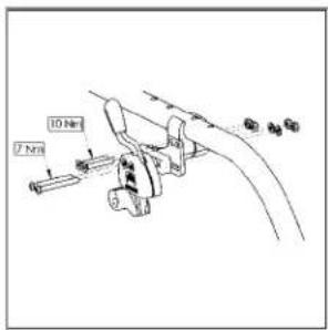
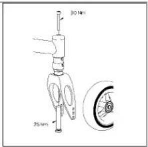
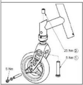
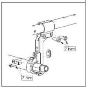
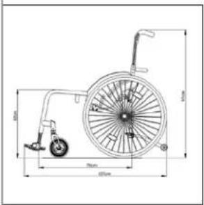


Fig.11.0
The torque for the M6 screw is 7 Nm, unless otherwise specified.
Voorwoord
Beste klant,
Sunrise Medical Ltd.
Sunrise Business Park
High Street, Wollaston
West Midlands DY8 4PS
Engeland
Tel: +44/1384-446622
Fax: +44/1384-446644
www.sunrisemedical.com

natural_image
Two illustrations of a person in wheelchairs on stairs, showing different mobility behaviors (no text or symbols)

natural_image
Illustration of a person wearing a helmet and holding a diagonal bar, standing on a chair (no text or symbols)
Transport >>>
natural_image
Pure white abstract shape on black background, resembling a stylized letter or symbol (no text or numbers)
natural_image
Front view of a black bicycle chassis with visible wheels and structural brackets (no text or symbols)
natural_image
Close-up of a modern wheelchair with a black SOPUR back cover (no visible text or symbols on the device itself)
natural_image
Close-up of a robotic arm with visible joints and a red base, no text or symbols present

natural_image
Close-up of a mechanical component with red clamps and a black SOPUR logo, no readable text or symbols beyond the label.
natural_image
Diagram of a bicycle with red support poles and a circular wheel, labeled Fig. K (no text or symbols on the diagram itself)
3.0 Gebruik
natural_image
Close-up of a bicycle wheel with visible spokes and a central hub, labeled as Fig. 2.0 (no text or symbols on the diagram itself)
OPGELET:
natural_image
Two-panel image showing a black SOPUR wheelchair device and its close-up of the wheel, labeled Fig. 3.0 and Fig. 3.1 (no text or symbols on the devices themselves)
5.0 Trapdop
Trapdop (Fig. 4.0)
natural_image
Close-up of a bicycle wheel with visible spokes and a curved handle (no text or symbols)
natural_image
Close-up of a mechanical component with clamps and brackets, labeled Fig. 6.0 (no readable text or symbols)
is;
natural_image
Close-up of a mechanical component with labeled parts, no readable text or symbols present
OPGELET:
natural_image
Close-up of a motorcycle wheel assembly with mechanical clamps and suspension components (no visible text or symbols)
OPGELET:
natural_image
Close-up of a mechanical assembly with a labeled component (1) and no visible text or symbols on the main structure.
natural_image
Close-up of a hand adjusting a mechanical component with a tool, labeled 'Fig. 6.5' (no readable text or symbols)

natural_image
Close-up of a hand inserting a component into a device housing (no visible text or symbols)
natural_image
Close-up of a bicycle's wheel and suspension mechanism, labeled as Fig. 6.9 (no text on the diagram itself)
natural_image
Close-up of a mechanical pulley system with black wheels and a metallic handle (no visible text or symbols)
natural_image
Close-up of a black and silver bicycle lunge with wheels and a handle (no text or symbols visible)
natural_image
Close-up of a black and white photo of a stroller with wheels and handle (no text or symbols visible)
Zithoogte
natural_image
Close-up of a bicycle's front wheel and suspension components, labeled 1, 2, and 3 (no text or symbols on the diagram itself)
Spoorinstelling Argon
natural_image
Mechanical assembly diagram showing a linkage mechanism with labeled component 1 (no text or symbols beyond label)
natural_image
Diagram of two vertical rods connected by a horizontal line, labeled Fig. 6.14 (no text or symbols on the diagram itself)
natural_image
Mechanical assembly diagram showing a clamp and bracket with no visible text or symbols
natural_image
Mechanical assembly diagram showing a bracket with mounting holes and a labeled section (Fig. 6.18), no readable text or symbols present.
natural_image
Close-up of a mechanical component with layered structure and mounting bracket (no visible text or symbols)
natural_image
Close-up of a black ergonomic chair with handle and seat, labeled as Fig. 6.21 (no text or symbols on the chair itself)
natural_image
Close-up of a bicycle seat frame with labeled components (1 and 2), no visible text or symbols beyond labels
Rugleuning
natural_image
Close-up of a robotic hand with a textured grip and labeled part '2' (no text or symbols beyond label)
Heupgordel
natural_image
Close-up of a mechanical component with visible wiring and a textured grip, labeled as Fig. 6.26 (no text or symbols on the object itself)
natural_image
Black-and-white photo of a dark, textured object with no visible text or symbols, labeled 'Fig. 6.27' in the corner (no readable document text or symbols on the object itself)
natural_image
Three black-and-white images showing different types of cable or cable accessories (no text or symbols visible)
natural_image
Person wearing a seatbelt and holding the spine, viewed from above (no visible text or symbols)
natural_image
Simple line drawing of a seated human figure in a chair, labeled 'Fig. 6.30' (no text or symbols on the figure itself)

natural_image
Close-up of two wheelchairs with labeled parts, no visible text or symbols on the main body
natural_image
Medical X-ray image showing internal anatomical structures with no visible text or symbols
natural_image
Black-and-white photo of a wheelchair bicycle with visible suspension and wheel (no text or symbols)
Transitwielen
Transitwielen (Fig. 6.36)
natural_image
Close-up of a bicycle wheel and suspension components (no text or symbols visible)
OPGELET:
natural_image
Green recycling symbol with four chasing arrows forming a triangle (no text or labels)
Sunrise Medical Ltd.
Sunrise Business Park
High Street, Wollaston
West Midlands DY8 4PS
Angleterre
Tel: +44/1384-446622
Fax: +44/1384-446644
www.sunrisemedical.com

natural_image
Two illustrations of a person in wheelchairs on stairs, showing different mobility behaviors (no text or symbols)

natural_image
Illustration of a person wearing a helmet and holding a diagonal bar, standing on a chair (no text or symbols)
natural_image
Pure white abstract shape on black background, resembling a stylized letter or symbol (no text or numbers)
natural_image
Front view of a car chassis with visible wheels and structural brackets (no text or symbols)
natural_image
Close-up of a black SOPUR wheelchair seat with visible latches and backrest (no text or symbols on the device itself)

natural_image
Close-up of a mechanical robotic arm with visible joints and a red component, no text or symbols present
natural_image
Close-up of a mechanical component with red clamps and a blue SOPUR logo, no readable text or symbols beyond the logo.

natural_image
Diagram of a wheelchair mechanism with red and black rods, no text or symbols present
3.0 Manipulation
natural_image
Close-up of a bicycle wheel with visible spokes and a central hub, labeled as Fig. 2.0 (no text or symbols on the diagram itself)
ATTENTION :
natural_image
Black SOUR VR headset with visible wheels and control panel (no text or symbols on device)
natural_image
Close-up of a person in a wheelchair wheelbase being adjusted for bicycle wheel (no visible text or symbols)
natural_image
Close-up of a bicycle wheel with visible spokes and a curved handle (no text or symbols)
natural_image
Close-up of a mechanical clamp or bracket component (no visible text or symbols)
natural_image
Mechanical component with labeled parts, no visible text or symbols
ATTENTION :
natural_image
Close-up of a mechanical assembly with black components and mounting brackets (no visible text or symbols)
natural_image
Close-up of a mechanical assembly with a labeled component (1) and no visible text or symbols on the main structure.
natural_image
Close-up of a hand using a tool to adjust or install a mechanical component, labeled 'Fig. 6.5' (no text on the object itself)

natural_image
Close-up of a hand holding an electronic device with labeled component '3' (no text or symbols on the device itself)
Roue avant
natural_image
Close-up of a bicycle stroller with visible wheels and handle (no text or symbols)
natural_image
Mechanical assembly diagrams showing four stages of wheel movement and angle adjustment (no text or symbols)
Hauteur du siège
natural_image
Close-up of a bicycle's front wheel and suspension components (no text or symbols visible)
Fig. 6.11
natural_image
Mechanical assembly diagram showing a linkage mechanism with labeled component 1 (no text or symbols beyond label)
natural_image
Diagram of two parallel cylindrical objects with a horizontal double-headed arrow, labeled Fig. 6.14 (no text or symbols on the objects themselves)
natural_image
Mechanical assembly diagram showing a linkage mechanism with labeled parts (no readable text or symbols)
natural_image
Technical line drawing of a mechanical component with mounting bracket and base (no text or symbols)
natural_image
Close-up of a mechanical device with straps and a central body, labeled Fig. 6.20 (no visible text or symbols on the device itself)
natural_image
Close-up of a black mechanical chair with handle and seat, labeled Fig. 6.21 (no text or symbols on the chair itself)
natural_image
Close-up of a bicycle's seat frame with labeled parts (1 and 2), no visible text or symbols beyond labels
Dossier
natural_image
Close-up of a robotic hand with labeled part '2' and figure number 'Fig. 6.25' (no other text or symbols)
natural_image
Close-up of a car tire being held by a strap, showing white cable and black bands (no text or symbols visible)
natural_image
Close-up of a dark, textured object with no visible text or symbols, labeled 'Fig. 6.27' in the corner (no other readable text or symbols)
natural_image
Person in a wheelchair wearing a seatbelt, no visible text or symbols
natural_image
Simple line drawing of a seated human figure in a chair, labeled 'Fig. 6.30' (no text or symbols on the figure itself)
Roulettes anti-bascule
Roulettes anti-bascule Quickie/Argon
(Fig. 6.32)
natural_image
Close-up of a wheelchair wheel with labeled parts (1, 2, and Fig. 6.32), no readable text or symbols beyond labels.
natural_image
Medical X-ray image showing internal anatomical structures with no visible text or symbols
Profondeur du siège
natural_image
Close-up of a black wheelchair with a wheel and armrest (no visible text or symbols)
Fig. 6.35
ATTENTION :
natural_image
Close-up of a bicycle wheel assembly with visible wheels and suspension components (no text or symbols)
ATTENTION :
natural_image
Green recycling symbol with four chasing arrows forming a triangle (no text or labels)

Sunrise Medical Ltd.
Sunrise Business Park
High Street, Wollaston
West Midlands DY8 4PS
England
Tel: +44/1384-446622
Fax: +44/1384-446644
www.sunrisemedical.com

natural_image
Two illustrations of a person in wheelchairs on stairs, showing different mobility behaviors (no text or symbols)

natural_image
Illustration of a person in a wheelchair holding a diagonal bar, labeled 'Fig. B' (no text or symbols on the figure itself)
Transporte >>>
natural_image
Pure electrical circuit symbol for a diode (no text or labels)
natural_image
Front view of a bicycle's front wheel and side-mounted platform (no text or symbols visible)
natural_image
Close-up of a modern wheelchair with a black SOPUR backrest and seat cover (no visible text or symbols)

natural_image
Close-up of a mechanical robotic arm with visible joints and a red component, no text or symbols present

natural_image
Close-up of a mechanical component with visible blue and red parts, no readable text or symbols
natural_image
Diagram of a bicycle steering wheel with red and black poles, showing angle and motion lines (no text or symbols)
3.0 Utilización
natural_image
Close-up of a bicycle wheel with visible spokes and a central hub, labeled as Fig. 2.0 (no text or symbols on the diagram itself)
natural_image
Black and white photo of a futuristic vehicle with wheels and a labeled 'SOPUR' on the side (no other text or symbols visible)

natural_image
Close-up of a person in a wheelchair wheelbase being adjusted for bicycle wheel (no visible text or symbols)
5.0 Tubos de cola
Tubos de cola (Fig. 4.0)
natural_image
Close-up of a bicycle wheel with visible spokes and a curved handle (no text or symbols)
natural_image
Close-up of a mechanical component with clamping mechanism and mounting bracket (no visible text or symbols)
natural_image
Close-up of a mechanical component with labeled parts, no readable text or symbols present
PRECAUCION:
natural_image
Close-up of a bicycle wheel assembly with visible brackets and mounting hardware (no text or symbols)
natural_image
Close-up of a mechanical assembly with a labeled component (1) and no visible text or symbols on the main structure.

natural_image
Close-up of a hand using a tool to adjust or install a mechanical component, labeled with number 2 and Fig. 6.5 (no text or symbols on the object itself)
natural_image
Close-up of a hand inserting a component into a device housing (no visible text or symbols)
Rueda delantera
natural_image
Close-up of a bicycle stroller with visible wheels and handle (no text or symbols)
natural_image
Mechanical assembly diagram showing four stages of a device with wheels and adjustment arrows (no text or symbols)
Altura del asiento
Ajuste de altura delantera del asiento (Armazón ajustable, Fig. 6.11)
natural_image
Mechanical assembly diagram showing a linkage mechanism with labeled component 1 (no text or symbols beyond label)

natural_image
Diagram of two parallel cylindrical objects with a horizontal double-headed arrow, labeled Fig. 6.14 (no text or symbols on the objects themselves)

natural_image
Mechanical assembly diagram showing a lever mechanism with labeled parts (no readable text or symbols)

natural_image
Technical line drawing of a mechanical component with mounting bracket and base (no text or symbols)

natural_image
Close-up of a mechanical component with layered structure and mounting bracket (no visible text or symbols)
natural_image
Close-up of a black mechanical chair with handle and seat, labeled Fig. 6.21 (no text or symbols on the chair itself)
natural_image
Close-up of a black bicycle seat with labeled parts (1 and 2), no visible text or symbols beyond labels
Respaldo
natural_image
Close-up of a robotic hand with labeled part '2' and figure number 'Fig. 6.25' (no other text or symbols)
natural_image
Close-up of a mechanical component with a textured grip, showing no visible text or symbols
natural_image
Grayscale close-up of a dark, textured object with no visible text or symbols
natural_image
Person in a wheelchair wearing a black belt, viewed from above (no visible text or symbols)
natural_image
Silhouette of a seated human figure in a chair, labeled 'Fig. 6.30' (no text or symbols on the figure itself)
natural_image
Close-up of a wheelchair with labeled parts (1, 2, Fig. 6.32), no readable text or symbols beyond labels
natural_image
Medical X-ray image showing internal anatomical structures with no visible text or symbols
natural_image
Black and white photo of a bicycle wheel with a black suspension bar, no visible text or symbols
Fig. 6.35
Ruedas de tránsito
natural_image
Close-up of a bicycle's front wheel and suspension components (no text or symbols visible)
PRECAUCION:
natural_image
Green recycling symbol with three chasing arrows forming a triangle (no text or symbols)
Sunrise Medical Ltd.
Sunrise Business Park
High Street, Wollaston
West Midlands DY8 4PS
Inglaterra
Tel: +44/1384-446622
Fax: +44/1384-446644
www.sunrisemedical.com

Como fabricante, a SUNRISE MEDICAL, declara que as cadeiras de rodas leves respeitam a directriz 93/42/EEC / 2007/47/EEC.

IMPORTANTE:
NÃO USE A SUA CADEIRA DE RODAS ANTES
DE TER LIDO E COMPREENDIDO O MANUAL.
Índice
natural_image
Two illustrations of a person in wheelchairs on stairs, showing different mobility behaviors (no text or symbols)

plana.
natural_image
Illustration of a person in a wheelchair holding a diagonal bar, labeled 'Fig. B' (no text or symbols on the figure itself)
Transporte >>>
natural_image
Pure diagram of a hook shape without any text, numbers, or symbols
natural_image
Front view of a car's lower body frame with black metal legs and wheels, no visible text or symbols
natural_image
Close-up of a person in a wheelchair seat with a black SOPUR back cover (no visible text or symbols on the device itself)
natural_image
Close-up of a mechanical robotic arm with visible joints and a red component, no text or symbols present
natural_image
Close-up of a mechanical component with red clamps and a blue SOPUR logo, no readable text or symbols beyond the label.

natural_image
Diagram of a wheel-mounted device with red and gray components, labeled Fig. K (no text or symbols on the diagram itself)
3.0 Manuseamento
natural_image
Close-up of a bicycle wheel with visible spokes and a central hub, labeled as Fig. 2.0 (no text or symbols on the diagram itself)
CUIDADO:
natural_image
Black and white photo of a wheeled device labeled 'SOPUR' with visible wheels and body (no text beyond label)

natural_image
Close-up of a person in a wheelchair wheelbase being adjusted for bicycle wheel (no visible text or symbols)
5.0 Tubos de Apoio
Tubos de Apoio (Fig. 4.0)
natural_image
Close-up of a bicycle wheel with visible spokes and a curved handle (no text or symbols)
natural_image
Close-up of a mechanical component with clamping mechanism and mounting bracket (no visible text or symbols)
natural_image
Close-up of a mechanical component with labeled parts, no readable text or symbols present
natural_image
Close-up of a bicycle wheel assembly with mounting brackets and levers (no visible text or symbols)
CUIDADO:
natural_image
Close-up of a mechanical assembly with a labeled component (1) and no visible text or symbols on the main structure.

natural_image
Close-up of a hand adjusting a mechanical component with a tool, labeled 'Fig. 6.5' (no readable text or symbols)
natural_image
Close-up of a hand holding a small electronic device component, labeled 'Fig. 6.6' with number '3' pointing to the component (no readable text or symbols beyond label)

Roda giratória
natural_image
Close-up of a bicycle stroller with visible wheel and handle (no text or symbols)
natural_image
Four-panel sequence showing mechanical components with wheels and a labeled angle of 8°, no text or symbols present.
Altura do Assento
natural_image
Close-up of a bicycle's front wheel and suspension components, labeled 1, 2, and 3 (no text or symbols on the diagram itself)
natural_image
Mechanical assembly diagram showing a linkage mechanism with labeled component 1 (no text or symbols beyond label)

natural_image
Diagram of two parallel cylindrical objects with a horizontal double-headed arrow, labeled Fig. 6.14 (no text or symbols on the objects themselves)

Encosto
natural_image
Mechanical assembly diagram showing a linkage mechanism with labeled parts (no readable text or symbols)
natural_image
Technical line drawing of a mechanical clamp or bracket component (no text or symbols)
natural_image
Close-up of a mechanical component with layered structure and mounting bracket (no visible text or symbols)
natural_image
Close-up of a black mechanical chair with handle and seat, labeled Fig. 6.21 (no text or symbols on the chair itself)
natural_image
Close-up of a bicycle seat frame with labeled components (1, 2), no visible text or symbols beyond labels
Encosto
natural_image
Close-up of a robotic hand with a labeled finger and part, no visible text or symbols
Cinto de segurança
natural_image
Close-up of a cable being inserted into a car wheel (no visible text or symbols)
natural_image
Close-up of a dark, textured object with no visible text or symbols, labeled 'Fig. 6.27' at bottom right (no other readable text or symbols)
natural_image
Person in a wheelchair wearing a belt and pants, no visible text or symbols
natural_image
Simple line drawing of a seated human figure in a chair, labeled 'Fig. 6.30' (no text or symbols on the figure itself)
natural_image
Close-up of a wheelchair with two wheels and labeled parts (1, 2), no visible text or symbols on the main subject.
natural_image
Medical scan image showing internal anatomical structures with no visible text or symbols
natural_image
Close-up of a black wheelchair with metal frame and wheels (no visible text or symbols)
Fig. 6.35
Rodas de viagem
natural_image
Close-up of a bicycle wheel and suspension components (no text or symbols visible)
CUIDADO:
natural_image
Green recycling symbol with four chasing arrows forming a triangle (no text or labels)

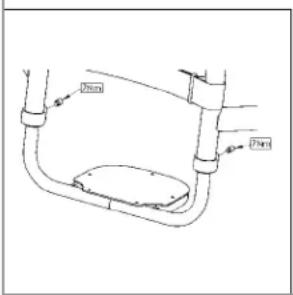
Fig. 11.0
Sunrise Medical S.r.l.
Via Riva, 20 - Montale
29122 Piacenza
Italia
Tel: +39 0523 573111
Fax: +39 0523 570060
info@sunrisemedical.it
www.SunriseMedical.com

natural_image
Two illustrations of a person in wheelchairs on stairs, showing different mobility behaviors (no text or symbols)

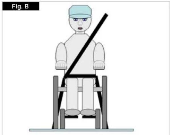
natural_image
Illustration of a person sitting on a chair with a diagonal bar, labeled 'Fig. B' (no text or symbols on the figure itself)
Trasportabilità >>>
natural_image
Pure white abstract shape resembling a stylized letter or symbol on black background, no text or symbols present
natural_image
Front view of a black bicycle steering wheel with visible wheels and a curved bracket (no text or symbols)

natural_image
Close-up of a modern wheelchair with SOPUR branding and seatbelt (no readable text or symbols beyond branding)
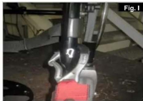
natural_image
Close-up of a robotic arm with visible joints and a red component, no text or symbols present

natural_image
Close-up of a mechanical component with visible wiring and a red lever, labeled 'SOPUR' (no readable text beyond label)
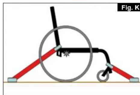
natural_image
Diagram of a wheelchair mechanism with red and gray rods, no text or symbols present
3.0 Uso
natural_image
Close-up of a bicycle wheel with visible spokes and a central hub, labeled as Fig. 2.0 (no text or symbols on the diagram itself)
ATTENZIONE:
natural_image
Black and white photo of a wheeled device labeled 'SOPUR' with visible wheels and body (no text beyond label)

natural_image
Close-up of a person in a wheelchair wheelbase being adjusted for bicycle wheel (no visible text or symbols)
5.0 Pedana per ribaltamento
Pedana per ribaltamento (Fig. 4.0)
natural_image
Close-up of a bicycle wheel with visible spokes and a curved handle (no text or symbols)
natural_image
Close-up of a mechanical component with clamping mechanism and mounting bracket (no visible text or symbols)
natural_image
Close-up of a mechanical component with labeled parts, no visible text or symbols
ATTENZIONE:
natural_image
Close-up of mechanical components with no visible text or symbols
ATTENZIONE:
natural_image
Close-up of a mechanical assembly with labeled component '1' and figure number 'Fig. 6.4' (no readable text or symbols beyond labels)

natural_image
Close-up of a hand using a tool to adjust or install a mechanical component, labeled 'Fig. 6.5' (no text on the object itself)

natural_image
Close-up of a hand holding an electronic device with labeled component '3' (no text or symbols on the device itself)
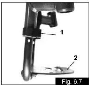
Ruota anteriore
natural_image
Close-up of a bicycle's wheel and suspension mechanism, labeled as Fig. 6.9 (no text or symbols on the diagram itself)
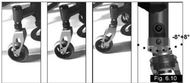
natural_image
Four-panel black-and-white photo sequence showing a mechanical device with wheels and a labeled angle of 8°, no text or symbols present.
Altezza seduta
natural_image
Mechanical assembly diagram showing a linkage mechanism with labeled component 1 (no text or symbols beyond label)

natural_image
Diagram of two parallel cylindrical objects with a horizontal double-headed arrow, labeled Fig. 6.14 (no text or symbols on the objects themselves)
natural_image
Mechanical assembly diagram showing a bracket with levers and fasteners (no text or symbols)
natural_image
Technical line drawing of a mechanical bracket or clamp assembly (no text or symbols)
natural_image
Close-up of a black mechanical component with horizontal bands and a small white connector, labeled 'Fig. 6.20' (no readable text or symbols on the object itself)
natural_image
Close-up of a black mechanical chair with handle and seat, labeled Fig. 6.21 (no text or symbols on the chair itself)
natural_image
Close-up of a bicycle's rear seat assembly with labeled parts (1 and 2), no visible text or symbols beyond labels
Schienale
natural_image
Close-up of a robotic hand with textured grip and labeled component '2' (no text or symbols beyond label)
Cintura pelvica
natural_image
Close-up of a mechanical component with a textured grip and cable, labeled as Fig. 6.26 (no readable text or symbols)

natural_image
Black-and-white photo of a dark object with a light-colored band, possibly a device or component, against a plain background (no visible text or symbols)
natural_image
Person adjusting a belt on a dark jacket, labeled as Fig. 6.29 (no text or symbols on the subject)
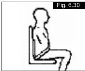
natural_image
Simple line drawing of a seated human figure in a chair, labeled 'Fig. 6.30' (no text or symbols on the figure itself)
natural_image
Close-up of a wheelchair wheel with labeled parts (1, 2, and Fig. 6.32), no readable text or symbols beyond labels.
natural_image
Medical X-ray image showing internal anatomical structures with no visible text or symbols
natural_image
Black-and-white photo of a wheelchair leg and wheel, labeled 'Fig. 6.35' (no other text or symbols visible)
Ruotine da transito
Ruotine da transito (Fig. 6.36)
natural_image
Close-up of a bicycle wheel and suspension components (no text or symbols visible)
ATTENZIONE:
natural_image
Green recycling symbol with four chasing arrows forming a triangle (no text or labels)
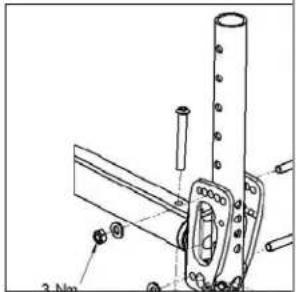
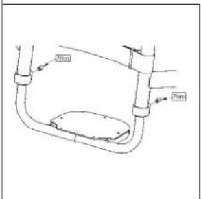
Fig. 11.0
Sunrise Medical Limited
High Street Wollaston
West Midlands DY8 4PS
England
Sunrise Medical S.A.
17, rue Mickael Faraday
Sunrise Medical A.G.
Lückhalde 14
3074 Muri bei Bern
Switzerland
Tel.: +41 (0) 31-958-3838
Fax: +41 (0) 31-958-3848
www.sunrisemedical.com
Sunrise Medical AS
Dynamitveien 14B
1400 SKI
Norway
Tel.: +47 66963800
Faks: +47 66963880
www.sunrisemedical.no
Sunrise Medical AB
Britta Sahlgrens gata 8A
Sunrise Medical B.V.
Groningenhaven 18-20
3433 PE Nieuwegein
Nederland
Tel.: +31 (0) 3060-82100
Fax: +31 (0) 3060-55880
www.sunrisemedical.no
G2 A/S
Graham Bells Vej 21-23 A
8200 Arhus N
Denmark
Sunrise Medical Pty. Ltd.
6 Healey Circuit
Huntingwood,
New South Wales 2148
Tel.: +61 (0)2 9678 6600
Fax: +61 (0)2 9678 6655
www.sunrisemedical.no