
TG120NC6 - Boiler GORENJE - Free user manual and instructions
Find the device manual for free TG120NC6 GORENJE in PDF.
| Brand | Gorenje |
| Model | TG120NC6 |
| Type | Electric storage water heater |
| Volume | 120 liters |
| Rated pressure | 0.6 MPa (6 bar) |
| Electric power | 2000 W |
| Supply voltage | 230 V ~ |
| Dimensions (H x W x D) | 1081 x 865 x 205 mm |
| Empty weight | 38 kg |
| Weight when full | 158 kg |
| Energy consumption (24h) | 2.60 kWh/24h |
| Mixed water volume at 40°C | 236 liters |
| Anti-corrosion protection | Enameling and magnesium anode |
| Adjustable temperature | 20°C to 75°C |
| Connection type | Closed (pressure) or open (non-pressure) |
| Maintenance | Anode inspection every 36 months |
| Anti-corrosion warranty | Subject to periodic inspection |
Frequently Asked Questions - TG120NC6 GORENJE
User questions about TG120NC6 GORENJE
0 question about this device. Answer the ones you know or ask your own.
Ask a new question about this device
Download the instructions for your Boiler in PDF format for free! Find your manual TG120NC6 - GORENJE and take your electronic device back in hand. On this page are published all the documents necessary for the use of your device. TG120NC6 by GORENJE.
USER MANUAL TG120NC6 GORENJE
Dear buyer, we thank you for purchase of our product.
PRIOR TO INSTALLATION AND FIRST USE OF THE ELECTRIC WATER HEATER, PLEASE CAREFULLY READ THESE INSTRUCTIONS.
THIS APPLIANCE IS NOT INTENDED FOR USE BY PERSONS (INCLUDING CHILDREN) WITH REDUCED PHYSICAL, SENSORY OR MENTAL CAPABILITIES, OR LACK OF EXPERIENCE AND KNOWLEDGE, UNLESS THEY HAVE BEEN GIVEN SUPERVISION OR INSTRUCTION CONCERNING USE OF THE APPLIANCE BY PERSON RESPONSIBLE FOR THEIR SAFETY.
CHILDREN SHOULD BE SUPERVISED TO ENSURE THAT THEY DO NOT PLAY WITH THE APPLIANCE.
This water heater has been manufactured in compliance with the relevant standards and tested by the relevant authorities as indicated by the Safety Certificate and the Electromagnetic Compatibility Certificate. The technical characteristics of the product are listed on the label affixed between the inlet and outlet pipes. The installation must be carried out by qualified staff. All repairs and maintenance work within the water heater, e.g. lime removal or inspection/replacement of the protective anticorrosion anode, must be carried out by the authorised maintenance service provider.
BUILDING-IN
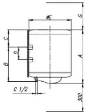
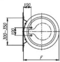
The water heater shall be built-in as close as possible to the outlets. When installing the water heater in a room with bathtub or shower, take into account requirements defined in IEC Standard 60364-7-701 (VDE 0100, Part 701). It has to be fitted to the wall using appropriate rag bolts with minimum diameter of 8mm . The wall with feeble charging ability must be on the spot where the water heater shall be hanged suitably reinforced. The water heater may be fixed upon the wall only vertically. We recommend the distance between the water heater and the ceiling is large enough to allow simple replacement of the MG anode (see dimension G in the Installation Drawing), in order to avoid unnecessary dismounting of the heater during the servicing intervention.
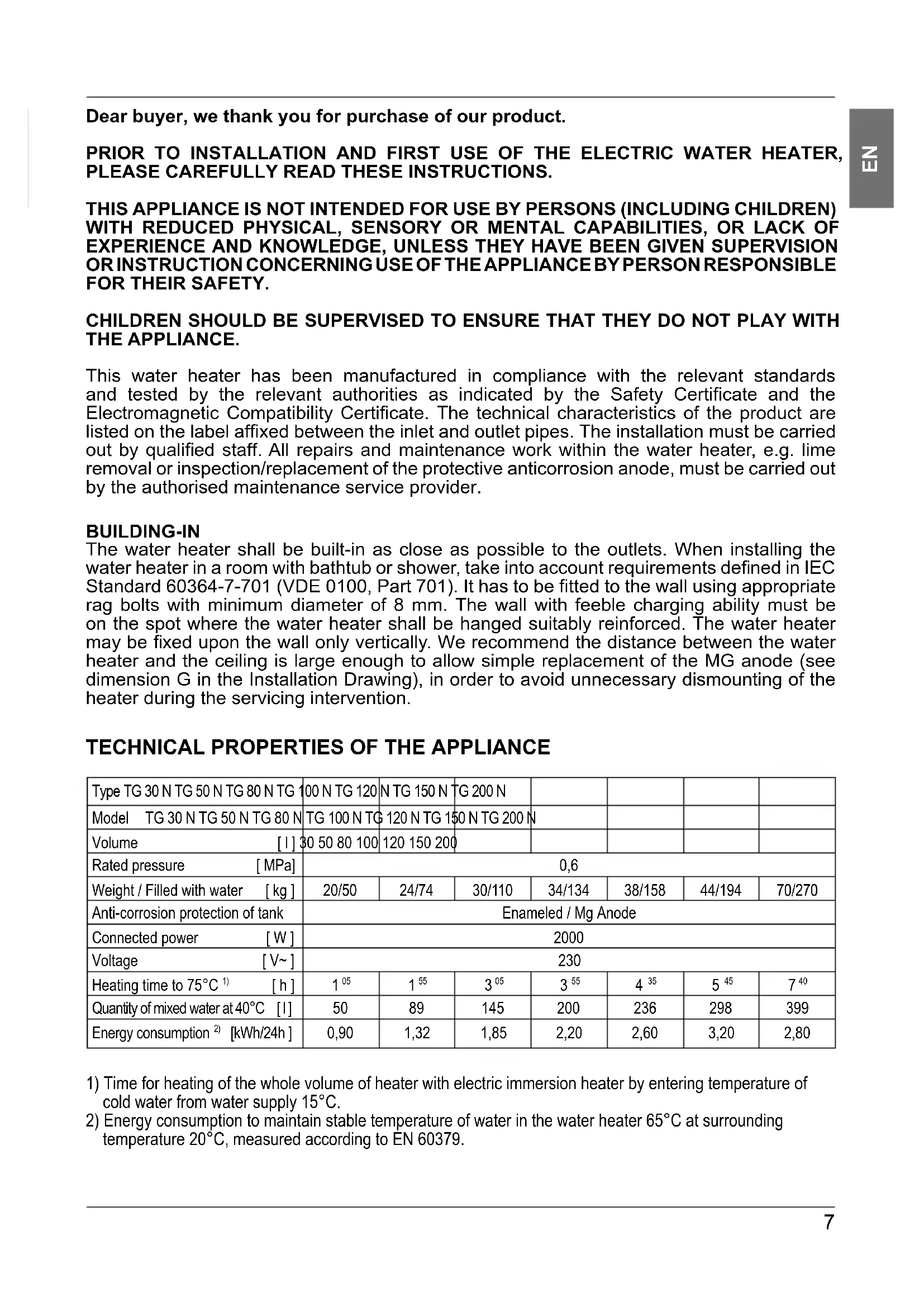
TECHNICAL PROPERTIES OF THE APPLIANCE
| Type TG 30 N TG 50 N TG 80 N TG | 100 N TG 120 | NTG 150 N | TG 200 N | ||||
| Model TG 30 N TG 50 N TG 80 N | TG 100 N TG | 120 N TG 150 N | TG 200 N | ||||
| Volume [I] | 30 50 80 100 | 120 150 200 | |||||
| Rated pressure [MPa] | 0,6 | ||||||
| Weight / Filled with water [kg] | 20/50 | 24/74 | 30/110 | 34/134 | 38/158 | 44/194 | 70/270 |
| Anti-corrosion protection of tank | Enameled / Mg Anode | ||||||
| Connected power [W] | 2000 | ||||||
| Voltage [V~] | 230 | ||||||
| Heating time to 75°C 1) [h] | 105 | 155 | 305 | 355 | 435 | 545 | 740 |
| Quantity of mixed water at 40°C [I] | 50 | 89 | 145 | 200 | 236 | 298 | 399 |
| Energy consumption 2) [kWh/24h] | 0,90 | 1,32 | 1,85 | 2,20 | 2,60 | 3,20 | 2,80 |
1) Time for heating of the whole volume of heater with electric immersion heater by entering temperature of cold water from water supply 15^ .
2) Energy consumption to maintain stable temperature of water in the water heater 65^ at surrounding temperature 20^ , measured according to EN 60379.
| A | B | C | D | E | F | |
| TG 30 N 459 | 275 173 | - 454 46 | 1 80 | |||
| TG 50 N 561 | 365 185 | - 454 46 | 1 130 | |||
| TG 80 N 766 | 565 190 | - 454 46 | 1 180 | |||
| TG 100 N 92 | 6 715 20 | 0 - 454 46 | 1 260 | |||
| TG 120 N 10 | 81 865 2 | 05 - 454 | 461 260 | |||
| TG 150 N 12 | 96 1065 | 220 - 454 | 461 260 | |||
| TG 200 N 15 | 05 1050 | 444 800 | 500 507 | 260 |
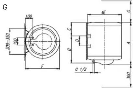
Connection and installation dimensions of the water heater [mm]
CONNECTION TO THE WATER SUPPLY
The water heater connections for the in-flowing and out-flowing water are colour-coded. The connection for the supply of cold water is coloured blue, while the hot water outlet is coloured red.
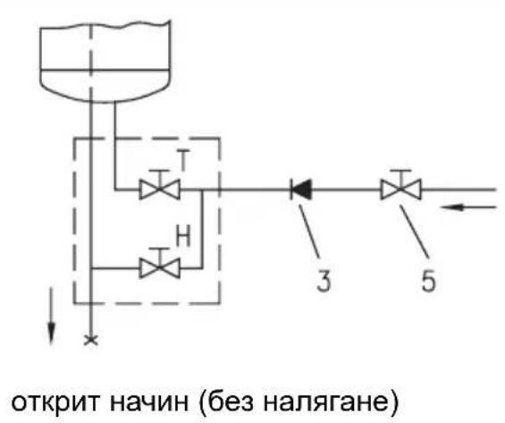
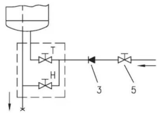
The water heater may be connected to the water supply in two ways. The closed-circuit pressure system enables several points of use, while the open-circuit gravity system enables a single point of use only. The mixer taps must also be purchased in accordance with the selected installation mode.
The open-circuit gravity system requires the installation of a non-return valve in order to prevent the water from draining out of the tank in the event of the water supply running dry or being shut down. This installation mode requires the use of an instantaneous mixer tap. As the heating of water expands its volume, this causes the tap to drip. The dripping cannot be stopped by tightening it further; on the contrary, the tightening can only damage the tap.
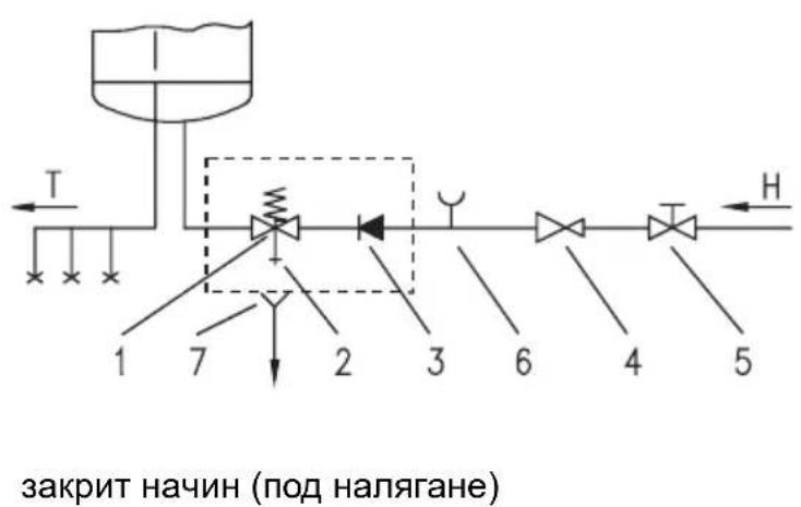
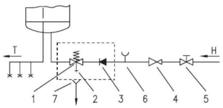
The closed-circuit pressure system requires the use of pressure mixer taps. For safety reasons the supply pipe must be fitted with a return safety valve or alternatively, a valve of the safety class that prevents the pressure in the tank from exceeding the nominal pressure by more than 0.1MPa . The outlet opening on the relief valve must be equipped with an outlet for atmospheric pressure.
The heating of water in the heater causes the pressure in the tank to increase to the level set by the safety valve. As the water cannot return to the water supply system, this can result in the dripping from the outlet of the safety valve. The drip can be piped to the drain by installing a catching unit just below the safety valve. The drain installed below the safety valve outlet must be piped down vertically and located in the environment that is free from the onset of freezing conditions.
In case the existing plumbing does not enable you to pipe the dripping water from the return safety valve into the drain, you can avoid the dripping by installing a 3-litre expansion tank on the inlet water pipe of the boiler.
In order to provide correct operation of the relief valve, periodical inspections of the relief valve must be carried out by the user. To check the valve, you should open the outlet of the return safety valve by turning the handle or unscrewing the nut of the valve (depending on the type of the valve). The valve is operating properly if the water comes out of the nozzle when the outlet is open.
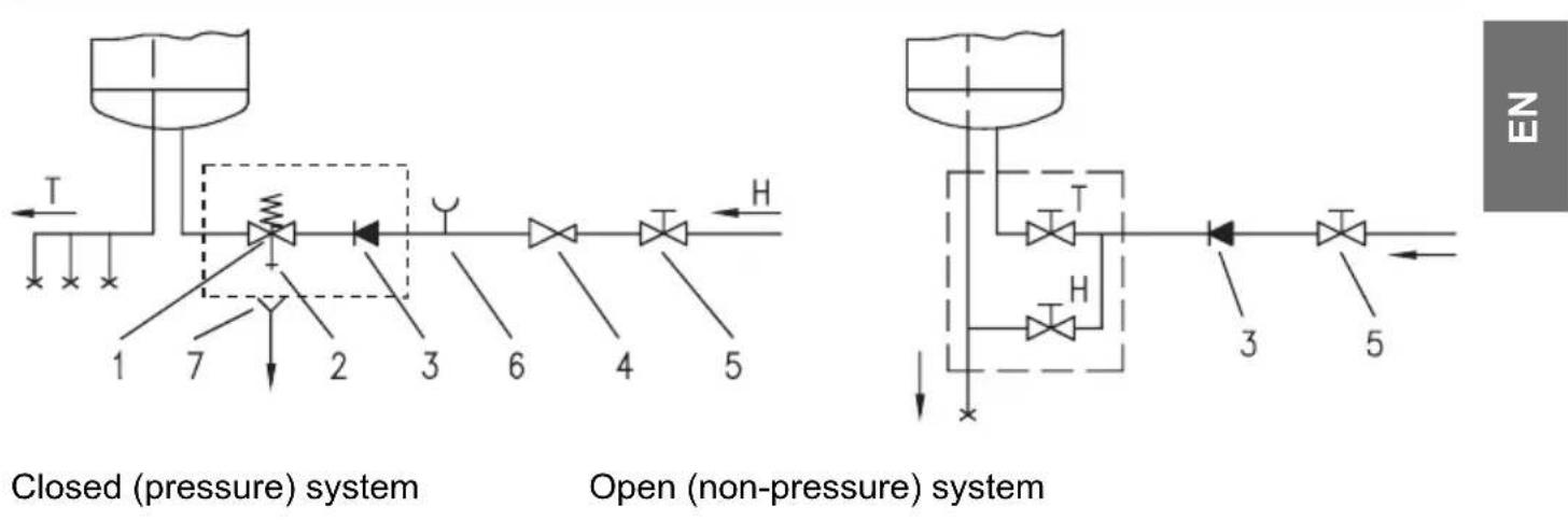
Legend:
1 - Safety valve 6 - Checking fitting
2 - Test valve 7 - Funnel with outlet connection
3 - Non-return valve
4 - Pressure reduction valve H - Cold water
5 - Closing valve T - Hot water
Between the water heater and return safety valve no closing valve may be built-in because with it the function of return safety valve would be impeded.
The water heater may be connected to the water network in the house without reduction valve if the pressure in the network is lower than 0.5MPa (5 bar). If the pressure exceeds 0.5MPa (5 bar), a reduction valve must be installed. Prior to the electric connection the water heater must obligatorily be filled with water. By first filling the tap for the hot water upon the mixing tap must be opened. When the heater is filled with water, the water starts to run through the outlet pipe of the mixing tap.
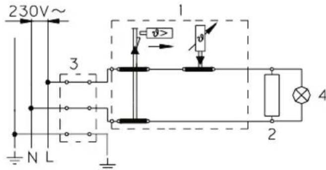
CONNECTION OF THE WATER HEATER TO THE ELECTRIC NETWORK
Before connecting to power supply network, install a power supply cord in the water heater, with a min. diameter of 1,5mm^2 (H05VV-F 3G 1,5 mm²). For it the protection plate must be removed from the water heater.
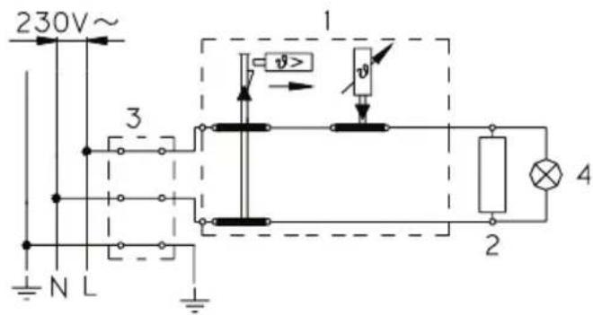
The connection of water heater to the electric network must be performed according to standards for electric installation. Install a disconnect switch (separating all poles from the power supply network) between the water heater and the permanent power connection, in compliance with the national regulations.
艺
Legend:
1 - Thermostat and bipolar thermal fuse
2 - Electric heater
3 - Connection terminal
4 - Pilot lamp
L - Live conductor
N - Neutral conductor
- Earthing conductor
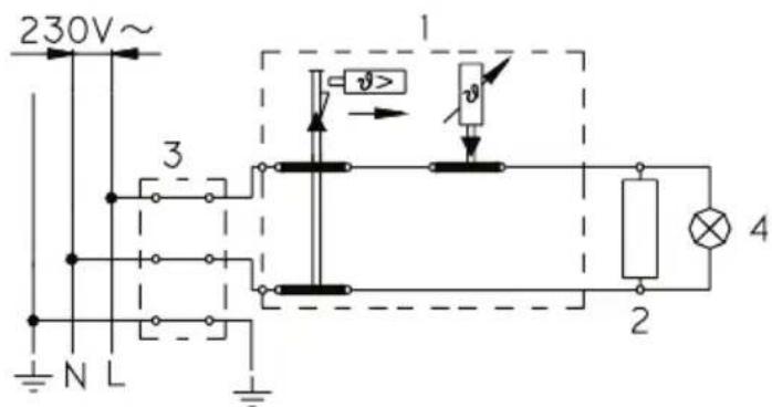
Electric installation
CAUTION: Prior to each reach in the inner of the water heater it must absolutely be disconnected from the electric network!
USE AND MAINTENANCE
After the connection to water and electric network the water heater is ready for use. Temperature of water in the appliance is automatically controlled by the thermostat which is adjusted by the manufacturer. The adjustment can be modified by turning of the adjustment screw upon the thermostat in the inner of the water heater. The adjustment range reaches between 20^ and 75^ . We do not recommend any change of the manufacturers adjustment, thus this ensures the most economical consumption of electric energy and the smallest excretion of lime-stone. The operation of electric immersion heater is shown by pilot light. On the casing of the water heater a bimetal thermometer is mounted, pointing clockwise (to the right) whenever there is hot water in the water heater.
When the heater shall not be used during a longer time, it must be disconnected from the electric network. At any risk for freezing of water in the water heater, the water must be emptied from it. Water is discharged from the heater via the inlet pipe. To this purpose, a special fitting (T-fitting) shall be mounted between the relief valve and the heater inlet pipe, or a discharge tap. The heater can be discharged directly through the relief valve, by rotating the handle or the rotating valve cap to same position as for checking the operation. Before discharge, make sure the heater is disconnected from the power supply, open the hot water on the connected mixer tap. After discharging through the inlet pipe, there is still some water left in the water heater. The remaining water will be discharged after removing the heating flange, through the heating flange opening.
The external parts of the water heater may be cleaned with a mild detergent solution. Do not use solvents and abrasives.
Regular preventive maintenance inspections ensure faultless performance and long life of your heater. The first of these inspections should be carried out by the authorised maintenance service provider about two years from installation in order to inspect the wear of the protective anticorrosion anode and remove the lime coating and sediment as required. The lime coating and sediment on the walls of the tank and on the heating element is a product of quality, quantity and temperature of water flowing through the water heater. The maintenance service provider shall also issue a condition report and recommend the approximate date of the next inspection.
Never try to repair any possible faults of the water heater by yourself, but inform about it the nearest authorised service workshop.
TEXHINUeCKN XAPAKTEPNCTUKN HA ANAPATA
| Вид TG 30 N TG 50 N TG 80 N TG | 100 N TG 120 N TG 150 N TG 200 N | ||||||
| Моden TG 30 N TG 50 N TG 80 N | TG 100 N TG 120 N TG 150 N TG 200 N | ||||||
| Обem [I] | 30 | 50 | 80 | 100 | 120 | 150 | 200 |
| Налгане [MPa] | 0,6 | ||||||
| Маса / Налълень с вoda [kg] | 20/50 | 24/74 | 30/110 | 34/134 | 38/158 | 44/194 | 70/270 |
| Аntникорозионен зашитей котел | Емайлиран / М.g катод | ||||||
| Мошист属实 Вкlioочвае [W] | 2000 | ||||||
| НарTEXени [V~] | 230 | ||||||
| Вреeme на заградан [h] | 105 | 155 | 305 | 355 | 435 | 545 | 740 |
| КолynchECTBO Смесна вoda属实 40°C [I] | 50 | 89 | 145 | 200 | 236 | 298 | 399 |
| ПOTравлике на[eilektpruchецво 2) [kWh/24h] | 0,90 | 1,32 | 1,85 | 2,20 | 2,60 | 3,20 | 2,80 |
1) Bpemeto 3a HapraBaHe Ha cenna o6em Ha 6oIepa C eJeKtpnueckn HarpeBaTeJ npn HauJaHa TempepaTpa Ha CTydeHata BOda OT BODonpoBOda 15^
2) Iontpe6IeHHeTo Ha eJektpuuecTBo npn noDpBkKaTa Ha nocToRHa TemepaTypa Ha BoDaTa B 6oJIePa ot 65^ n npn aTMocfepHa TemepaTypa 20^ , n3MepeHa no EN 60379.
| A | B | C | D | E | F | |
| TG 30 N 459 | 275 173 | - 454 46 | 1 80 | |||
| TG 50 N 561 | 365 185 | - 454 46 | 1 130 | |||
| TG 80 N 766 | 565 190 | - 454 46 | 1 180 | |||
| TG 100 N 92 | 6 715 20 | 0 - 454 4 | 61 260 | |||
| TG 120 N 10 | 81 865 2 | 05 - 454 | 461 260 | |||
| TG 150 N 12 | 96 1065 | 220 - 454 | 461 260 | |||
| TG 200 N 15 | 05 1050 | 444 800 | 500 50 | 7 260 |

G
BknIOUbaHe n MOHTaXHn pa3Mepn Ha 6oJIepa [MM]
CBbP3BAHE C BOIOPOBODA
BxodnT n 3xodnT kaHan 3a BodaTa ca OT6en3aHn Ha Tpb6nte Ha 6oJepa cbc CbOTBeTHn cBraT. BxodnT kaHan 3a CTydeHaTa Boda e B CInhbo, a n3XODnT Ha TOnnata Boda - B UepBeHo.
MozheTe Da CBpKte 6oJnepa C BODOpOBoDa NO Dba HauHna. 3akpnTnT Haun, NOD HAJIraHe, PO3BOJRABa BKN IQUBaHe Ha HAKOJIKO I3BOJa. OTKPnTnT Haun, 6e3 HAIraHe PO3BOJRABa cMo eDIn H3BOD. B 3aBNCIMoCT OT I36paHaTa CnCTema Ha CBbP3BaHe, Tp8Ba Da ce ChA6dIte n CbC CbOTBeTHnI 6poi CMEcnteHN 6aTeprn. Ppi OTkpTnHaun, 6e3 HAJIraHe, Ppei BoJnepa Tp8Ba Da ce BrpaDi BENTINKlana, KOITo Da CNIPA u3TuHaHeTo HA BOda OT KOTeJa, aKO BB BODOpOBoDA Hma BOda. Ppi To3n Haun Ha CBp3BaHe Tp8Ba Da n3NoI3BaTe 6aTeprn C npetoBaHe. Ppi 3aRpaBAHeTo Ha BOdaTa OBemblr Ce yBeJIuHaBa n 3anoYBa Da Kane ot Tpb6aTa Ha CMEcNTeHNata 6aTeprn. HMa Da MoXeTe Da cnpTe KaneHTo cMoC bC 3dPaBO 3aTgAre He KaPChETo Ha 6aTeprnTa, Taka Camo Ue Pa3BaIInTe. Ppi 3akpTnHaUHH, NOD HAIraHe, Ha BCEKn I3BOD Tp8Ba Da MOHTnPate CMEcNTeHLa 6aTeprn. Ha BXoHATA Tpb6a, nopadi 6e3OnacHocT, 3adblknteHIO Tp8Ba Da ce CLOxN BeHTnla INI rpyna, KOrTO ue PpeDnA3Ba HAIraHe B HArpeBaTeIa Da He ce KaUn 3a Nobuee ot O.1 MPa ot No3BoJeHO. OTTOUYHrT OTBOP Ha PpeDnA3HnB EHTINI 3aDbIxxNtELHo Tp8Ba Da nMa n3XoD KbM aTMOCFepHo HAIraHe.
Iprn HarpraBaHTo Ha BODaTa B 6oJnepa HAnraHTo B KOTeJa Ce NobuShaBa Do CTeneHa, HarglaceHa Ha 3aunTHnB eHTn. TbK aTO BpUaHTo Ha BODa o6paTHO BvB BODOnpoBDo a E b3npenrTCTBaHO, MoKe Da 3anOue He da Kane OT OTouHn OTBOP Ha 3aunTHn BeHTn. KaneaTa BODa MoKeTe Da npelte Te Upe3 OTouHn HakoHeuHk, aKO rHaMeCTnte N0d 3aunTHn BeHTn. I3xOHaTa Tp6a Tp6Ba Da ce CNoXn N3noD BeHTnla Ha 6e3onacHoCT, T8Ba Da e HacoYeHa npaBO Ha-DOny, B cpeDa KoYTo He 3ambp3Ba.
Korato nopadi HeydobHa HcTanaHrMa Bb3MOxHOCT, BoDaTa KOaTO KaN OOBpaTeH BeHTn 3a 6e3oNaCHocT, da ce npekapa B KaHaI, MOxe BMeCTO TOBa Da ce BrpaDn EKCpHaH3IOHeH CbD CbDbPkaU 3 J BOda BbpXy Tpb6aTa Ha HarpeBaTeJI.
3a npabnHTo DeiCTBHe Ha npedna3HnB BeHTnI Tp8Ba cAmn nepnoDnHo Da n3BbPbBaTe KOHTPOI. Pn npOBepka C DmXKeHne Ha pUka IIN OdBVAhe Ha raKa (3aBnCn OT MoeJa) BeHTnI 3a 6e3OpacHOCT Tp8Ba Da ce OTBOpN. OT Hero Tp8Ba Da n3Teue BODa, Koeto O3HaayBa Ye BeHTnIbT pa6Ot 6e3 rpeShka.
JereHda:
1-3auntha knana
2-Klana3aTeCTBaHe
3-Knana6e3Bpbuane
4-Klana 3a HamaJraBaHe Ha HalaRaHeTo
5-Cnnpauna Kna
6 - Yact 3a TectBaHe
7-Фунязиэхога
H-CTydeHa Boga
T-Tonna Boda
He 6nBaJa nocTaBAre BeHTnJ 3a CnpaHmexy BoJlepau N oBe3OnacraBaunr BeHTnJ, 3aIoTO ige HapBaNTe HeBb3MOxHO DeIcTBnETo Ha oBe3OnacraBaunr BeHTnJ.
Mokete da BkIouhte 6oJnepa KbM BoOpOBoDa B Doma Cn 6e3 BeHTn 3a HamaJIaBaHe Ha HAnraHTo, aKo HAnraHTo BvB BoOpOBoDa e noD 0,5 MPa (5 bar). Korato HAnraHc e no-BuCko ot 0,5 MPa (5 bar), 3aBnJxntEnHo Tp6Ba Da ce orpaN BeHTn 3a peDyKzna. IpeDi da BkIouhte 6oJnepa, Tp6Ba 3aBnJxntEnHO da ro HAnbLnHtEc BOda. Ppi PbBOTo nblHe OTbOpTe KpaHceto 3a ToPnata BOda Ha CmecntenHaTbAtepy. BoJnepbT e nblHe, aKO BOdAta 3anOChE Da Teue CINHO OT Tpb6aTa Ha CmecntenHaTbAtepy.
CbP3BAHE KbM EJEKTPUeCKATA MPEKA
IpeHn BkIIOUBaHe B eIeKTPnueckaT a MpeXa 6oJIepbT Tp8Ba Da ce 3a3EMN C npOBODnK cbcceHne Hau-MaIKo 1,5 MM² (H05VV-F 3G 1,5 MM²). Cbbp3BaHeto KbM eIeKTPnueckaTa MpeXa Tp8Ba Da 6bDe n3BbPseHO BbB CbOTBcTcBne C dHaarpamata N DeiCTBaUnTe CTaHApTn. MeJy HarpeBaTeJra 3a BoDATA I NOCTOHHATA INHCTaNaunr Tp8Ba Da 6bDe BRpaJeH DByIOnIOCeH PpeBKnIOuBaTeJ 3a eHNOBPeMeHHO PpeKbCBAHe Ha DBaTA npOBODnKa OT 3axpaHbaUaTa MpeXa CbJIacHO HaUNOHJHTE INHCTaJIaUNOHN INpeDncaHnY.
B
JereHda:
1 - Tepmoctat, 6mMetaHa
pha3a
2-HarpeBaTeN
3 - TepMHaJIHa Bpb3Ka
4-KoHTpOHaJaMaNnUka
L-Фаэн пов好吗
N-HeytpaJIeH npOBoDnK
-3aunTeH npoBODnK
CxemaHa eIeKTpueckaTa MpeKa
IIOJI3BAHE I NOIDPbJxKA
CneB KbluBaHTo B ToKa N BoOnpoBoda 6oJIepeT e roTOB 3a non3BaHe. TemnepaTypaTa BbB BbTpEshOCTTa Ha ypeDa ce KOHTpOInpa OT TepMOCTa BbB BbTpEshOCTTa, KOIToe HAcTpoEH fapbnuHO Ha Hau-IKOHOMNUHO NOLOXeHne, rapaHTnpaIo MmHMaJIHOOTpe6IeHne Ha eJeKtpUeCKa eHepnra, MmHMaJIHN 3aRy6n Ha TOJIINHa, MmHMaJIHO OTIgAraHe Ha BApOBVK BbpxU Kopnyca n MmHMaJIHN pa3XODn 3a pa6Ota. IIO BaSe JcJAHne pNOJOKeHHeTo Ha TepMOCTata MoKe Da 6bDe npOMEHeO NocpeDCTBOM BnHT KOITo Ce Hamnpa NaTepMOCTata. DnaNa3OHa Ha npomHa e MeKdy 20-75°C. Korato 3aBbptnte MaKcImaJIHo Ha JIABO BVE N3KlIOUBAte HarpeBaTeJHHra eJeMeENT. IpomHa Ha fapbnuHaTa HAcTpoKa He ce npenopbYBa.
KoHTpOHaTaNAMNnUka NOKa3Ba, Ye 6oJIePa pa6Ot. Ha OKoHata cIINHdpuHa IOBbpxHOCT Ha 6oJIePa ce HAmnpa 6mMetaJIHHrT TepMometbp, KOTo Ce OTKIOHOBA nO NOcoka Ha YacOBnKObAta CTpeJIka HADrCHO, KOrato B 6oJIePa mTaTONla Boda.
Ako ypeiBt Hama Da ce n3noJ3Ba 3a DbIbI nepNoD OT BpeMe, n3KJIIOUeTe ro ot eNeKtpnueckata Mpeka, Ho 6bDeTe cInyprHn Ye ppe3 To3n nepNoD Hama Da 6bDe Doynchato 3ampb3BaHe. BODATA OT BoIInepa Ce n3TOUBA ppe3 OTTOHaT TaB6a Ha BOIIepa. 3a Ta3n ZeI CE npenOpBvBa NO BpeMe Ha INCTaJInpaHETo MeXdy npedna3Hn BEHTIN N OTTOHaT a Tpb6a Da ce CLOxN CNEuAnEn FHTNH (TPOHN) IIN N3NYCKaTeJeH BeHTIN. BODATA OT BoIInepa MoKe Da ce n3TOUc CbIo HeNOCpeIDCTBeHO ppe3 npedna3Hn BEHTIN CbC 3aBbPtaHe Ha PbYkata IIN Ha BbpTJAata Ce KanaUka Ha BeHTINa B N0IOXeHne KaKTO npn PpOBepKa Ha DeEChTBHeTo. PpeDN n3TOUBAHeTO HarpeBaTeJrT pr6Ba Da ce n3KJIIOUH OT eNeKtpnueckata Mpeka I Da ce OTBOPn PbKOXBAtKaTa 3a TOIIa BODa Ha BKIOUeHata CmecnteHa batepN. CneD n3TOUBAHeTO Ha BODATA ppe3 OTTOHaT TaB6a B BoIIePa OCTaBA MaIKO KOJIueCTBO BODA, KOAYo n3TNUa Ppi Pa3BUBaHETo Ha XOJIeHDbpa Ha BOIIePa Ipe3 OTBOPa Ha BOIIePoBnX OJENDbp.
IobbpxhocTt ha 6oJIepa YnCTeTe cbc cna6 pa3TBop OT cTepInJeH npenapaT. He noJ3BaIte pa3peiNTeIN i CINHN NOUcTBAuN IpenapaTN.
Upe3 peoOBHn cepBn3HN npereJeN ige cn ocHypnte 6e3npo6mno nol3BaHe n DblbJxNBOT Ha 6oIepa. TpbBnT npereJe Tp8Ba Da 6bDe HnPaBeH OT yIbJIHOMOueH CepBn3 DBe rOHN cIeB KJIIOuBaHTo. Pn npereJa cIeBa Da ce yCTaHOBn daJIe E n3HOceH 3aunTHnAHOJ IN pRn Heo6XODIMOCT Da ce NOuchtn BODHnT KaMbK, KaTO Ce OTHTa KaueCTBOTo, KOJIueCTBOTo n Tempepatypata Ha BODaTa B 6oIepa. Pn npereJa Ha 6oIepa, B 3aBNCIMOCT OT CbCTOARHeTo My, cepBn3bT ige BN npenopbua cIeDbaUa daTa 3a npOBepKa Ha CbCTOARHeTo.
Molm, npEeHTyaJIHn NOBpeHn Ha 6oJNepa, He rO nonpaBraIte camn, a ce oBbPheTe KbM Hau-6JIH3KIn yIbJIHOMOuSeH cepBN3.
3aTbOpEn CnCTeM (noI npNTuCKOM)
OTBOpEN CnCTeM (npoTouHn)
JereHda:
1-CnrgyphOCHNBEHTNJ
2-Bentn3a TectnpaHe
3-HenobpaTHNBeHTNJ
4-BeHTnJI 3a peDyKunjy npTncka
5-3anopnBeHTnJ
6 - Tecthn HactaBak
7-LeBaK ca npNKbUyKOM Ha ODbOa
H-XnaHa Boga
T-Tonna Boda
I3meHy 6oJnepa n nobpaTHOR cnryphOCHor BeHTnla He cMe ce yrpaAnTu BeHTnla 3a 3aTbapaBe Bode jep 6n Ce TIme OHemoryhHnlo DeNoBaBe cnryphOCHor BeHTnla.
Bojlep ce moxe 6e3 yrgaIbe peyKTopcKor BeHTnla npNKJbUHTn Ha kyHny BODOBOnHy nHctanaunjy akoje npTncak Boe y nHctanaunjn HxN oD 0,5 MPa (5 6apa). Ako npTncak npena3n 0,5 MPa (5 6apa) obabe3Ho yrgaIte peyKcIOHn BeHTnI.
Ipe Hero uTo npKbUyHte 6oJnep Ha eJeKtpuHy Mpexy oBaBe3Ho ra HanyHnte BODom. IprnIKOM npBOr nyBeHa OTBOpHTe cnaBnHy 3a TOnny Body. BoJnep je npN kaN i3 cnabnHe noUHe da Teue B0da.
PKNKbUyUBAHe HA EJEKTPuHy MPEXY
Ipe npKbUHbHa ha eektpnHy mpexy notpe6Ho je y rpeja yrpadntn npNKbUHy TpaKy MNImaHnHr npeceka makap 1,5 MM² (H05VV-F 3G 1,5 MM²). Da 6n ce To yuHnNo, Tpe6a OdbTu 3aHTtHn NOKlonau Ha 6oJnepy. PpKbUHbAbe 6oJnepa Ha eektpnuHy mpexy mopa ce obabTu y cKnady ca cTaNapdima Koju Baxke 3a eektpnuHe IHCTanaJe. H3mehy rpejaya Boe i Tpajhe INcTaIauJe mopa 6tuYrpahe naPnpema 3a pa3DbajaBe IIOBa oD mpexe 3a HanaJaBe y cKnady ca NaOnOHm INcTaIauOHNm npOpncMa.
#
JereHda:
1 - Tepmoctat N DBOONH TOIIOTHN OCNypa
2 - Геяч
3-Прнкьуне клемe
4-KoHTpOHa cBETnJbKa
L-Φa3a
N-HeytpaJIHn BOJ
-ymbehe
Cxema noBe3nBaHa eJekTpnuHnx BODoBa
YIPO3OPEHbE: Ipe cBaKe nHTepBeHcUne y yHyTpawhocTn 6oJnepa o6aBe3Ho NCKbByuTe 6oJnep u3 eJeKtpnue MpeXe!
YNOTPEBA N ODPXABAHBe
IopnKbUyBaBy Ha BODOBHy n eJeKtpuHv Mpexuy, rpejaue je cnpemah 3a ynoTpe6y. Temnepatypy Boe y bojnepy ayTomatckn peryniwe pa6pnk noDeuhen Tepmoctat. Temnepatypa ce HOke noDeuBaTu OKpeTaHbem BnjkHa TepMoCTaty y uHyTpaShbOcTN Bojnepa. NOpduje noDeuBaHa ce Kpeh oD 20 do 75^ . He npenopyjemo Bam da MeBaTe pa6pnk noDeuHv Temnepatypy jep je To Temnepatypa Ha kojoj je notpoHba eNeKtpuHne eHeprnje ekOHOMNuHa, a TaIOKeHe KaMeHca HajMaBe.
Дeноаье eNeKtpnHOr eIemEHTa 3a rpejahe noka3yje KOHTpOJHa cBeTnJBka.「pejau mHa Na ИВици bIMetalHn Tepmometap, KoJn ce nokpeh y cmepy Ka3aJIbKe Ha caty y Deecho, KaJa je y rpejaay npcsyTHa TOnla BODa. Ako 6oJnep He HamepaBaTe da KopncTnte duXe BpeMe, NCKbUyHTe ra n3 eNeKtpnue Mpexe. Ako noctojn onachocT da ce BODa y 6oJnepy 3aMP3He, IcnpCTnte BODy n3 6oJnepa. BODa n3 rpejaya ce npa3HN Kpo3 doToCHy ueB rpejaya. Y TOM zuBy npenopuybHBO je npuiNKOM yrpaIbHe n3MeHy cnryphochor BeHTnla IdoToCHne CEBN rpejaBa HameCTNIOce6an fitting (T-deo) nIn ncynchn BEHTnI.「pejau MOkete nCnpa3HNTn TakoHe n HENOCPeDHO Kpo3 cnryphocHn BEHTnI NOMepaHem puYnce, OndocHo o6PThe KanuCe BeHTnla y nONoxaj Kao npuiNKOM npOBepaBaHa pada. Ipe npaxHBeBa rpejau Tpe6a NCKbUyHTn n3 eNeKTPnue Mpexe i 3aTM OTBOPHTn pyuCy 3a TOnLy BODy Ha npNKbUyeHoJ 6atepnjN 3a Me7aHe. Nocle npaxHBeBa BoDe Kpo3 doToCHy CEv, y rpejaay octaje MaHa KaONuHnA BoDe KoJa nCTnue npuiNKOM odCTpaHBNaBa rpejHe φIahWe (nocyBpaHehor oboda ueB) Kpo3 OTBOp rpejHe φIahWe.
Kyuhtte rpejau chntte 6narn pacTBOPom npaoka 3a npahe. He ynotpe6babajte pa3pehnuBaue nnn rpyba cpeDCTBa 3a nuShnebe.
EФикасо DeNoBaJIe 6e3 rpeuKn I dyr JxNBoTHN BEK rpejaa, omOryhInhe PeEOBHM cepBnCHIM npeIeDIma. 3a npepHaJn KOtao rapaHcJna BaXn cAmO aKO cTe peEOBHO cnpOBdJIIN npOnICAHe peoBHe npeIeDe nCTpoWeHocTn 3aHTtInHe aHOJe. Nepnoi3MeHy nojeHHaHnX peoBnHX npeIeDa He CME da 6yde duJxN oD 36 Meceu. NpeIeDe Mopa Da obABn OBlaaHEn cepBncep, KoJn Taj 3axBaT perncTpye Ha rapaHTHom JnCTy npOn3BOJa. Kod npeIeDa npOBepaba nCTpoWeHocT nPOTIKOP03NBHe 3aHTtInThe aHOJe I NO nOTpeBn OChtNiH e BODKn KameHauc KoJn Ce, ca Ob3npom Ha KBaIITet, KOJIuHHy IN TempepaTy pNotpoWeH e BoJe, ckyn y rpejauy. CepBnCHA cnyk6a he Bam Ha ochoby cTaBa KoJe je yrotOBnla npenOpuyNT DaTym 3a HapeDu KOHTPOLy.
Molnmo Bac eBentyaIHe KBapOBe rpejaHa HemoJTe nonpaBbAtn CamN, BeD O Hjima o6aBeCTnte Haj6nKy cepBnChy clyx6y.
Štovani kupče!
Zahvaljujemo Vam na povjerenju što ste nam ga iskazali kupnjom našeg proizvoda. MOLIMO VAS DA PRIJE MONTAZE I PRVE UPORABE POMNO PROČITATE UPUTE ZA MONTAZU, UPORABU I ODRžAVANJE ELEKTRICNE GRIJALICE VODE.
UREDAJ NIJE NAMENJEN ZA KORISÇENJE OSOBAMA (UKLJUCUJUCI I DECU), SA SMANJENIM FIZICKIM, PSIHICKIM ILI MENTALNIM SPOSOBNOSTIMA ILI BEZISKUSTVA TJ. ZNANJA, OSIM AKO SU POD NAZOROM ILI UPOZNATI SA UREDAJEM OD STRANE OSOB ODGOVORNE ZA NJIHOVU BEZBEDNOST.
DECA MORAJU BITI POD NAZOROM KAKO BI SE SPRECILO DA SE NE IGRAJU SA UREDAJEM.
Grijace izraeden u skladu sa vazećim standardima i službeno je testiran. Za njega je izdan sigurnosni certifikat i certifikat o elektromagnetskoj kompatibilnosti. Osnovne tehnicke karakteristike bojlera navedene su na natpisnoj tablici, naljepljenoj izmedu priključnih cijevi. Bojler priključuje na vodovodnu i elektricnu mrežu isključivo za to osposobljena stručna osoba. Zahvate u njegovu unutrašnjost zborg popravka, uklanjanje vodenoga kamencate provjere ili zamjene zašitne anode protiv korozije obavlja isključivo ovlastena servisna služba.
MONTAZA
Grijalicu montiramo ste je moguce blie potrošackom mestre. Ako budete grejac ugradili u prostoriju gde se nalazi kada za kupanje ili tus, obavezno treba uvažavati zahteve standarda IEC 60364-7-701 (VDE 0100, Teil 701). Na zid ga pričvrstite dvjema vijcima za zidove nominalnog promjera minimalno 8 mm. Ako je zid namijenjen montaži grijalice nedostatne nosivosti, moramo ga primjereno ojačati. Grijalicu smijemo pričvrstiti na zid isključivo u okomitu položaju. Zbog lakse kontrole i zamene magnezijumove anode preporucujemo vam da izmedu vrha grejaca i tavanice ostavite dovoljno prostora (vidi meru G na skici priključnih mera). U suprotnom slučaju biće prilikom navedene intervencije potrebno grejac demontirati sa zida.
TEHNICKE ZNAÇAJKE APARATA
| Tip TG 30 N TG 50 N TG 80 N TG 100 N TG 120 N TG 150 N TG 200 N | |||||||
| Model TG 30 N TG 50 N TG 80 N | TG 100 N TG | 120 N TG 150 N TG 200 N | |||||
| Korisni volumen [I] | 30 | 50 | 80 | 100 | 120 | 150 | 200 |
| Nominalni tlak [MPa] | 0,6 | ||||||
| Masa grijalice/napunjene vodom [kg] | 20/50 | 24/74 | 30/110 | 34/134 | 38/158 | 44/194 | 70/270 |
| Zašita kotla od korozije | emajlirano / Mg anoda | ||||||
| Snaga elektricnog grijača [W] | 2000 | ||||||
| Prikljuci napon [V~] | 230 | ||||||
| Vrijeme zagrivanja do 75°C 1) [h] | 105 | 155 | 305 | 355 | 435 | 545 | 740 |
| Količina miješane vode pri 40°C [I] | 50 | 89 | 145 | 200 | 236 | 298 | 399 |
| Energetski gubici 2) [kWh/24h] | 0,90 | 1,32 | 1,85 | 2,20 | 2,60 | 3,20 | 2,80 |
1) Vrijeme zagrijavanja cnejokupne prostornine grijalice elektrichim grijačom pri ulaznoj temperaturi hladne vode izvodovodne mreže 15^ .
2) Energetski gubici pri odžavanju konstantne temperature vode u grijalici 65^ i temperaturi okoline 20^ , mjereno prema EN 60379.
| A | B | C | D | E | F | |
| TG 30 N 459 | 275 173 | - 454 46 | 1 80 | |||
| TG 50 N 561 | 365 185 | - 454 46 | 1 130 | |||
| TG 80 N 766 | 565 190 | - 454 46 | 1 180 | |||
| TG 100 N 92 | 6 715 20 | 0 - 454 4 | 61 260 | |||
| TG 120 N 10 | 81 865 2 | 05 - 454 | 461 260 | |||
| TG 150 N 12 | 96 1065 | 220 - 454 | 461 260 | |||
| TG 200 N 15 | 05 1050 | 444 800 | 500 50 | 7 260 |
G
