MIC7000 Illuminator - Surveillance Camera BOSCH - Free user manual and instructions
Find the device manual for free MIC7000 Illuminator BOSCH in PDF.



| Product Type | Infrared illuminator for surveillance camera |
| Brand | Bosch |
| Model | MIC7000 Illuminator |
| Compatibility | Bosch MIC7000 cameras (except very low temperature models) |
| Safety standard | IEC 62471 Risk Group 1 (infrared and blue light) |
| Lighting technology | Infrared LED |
| Number of fixing screws | 3 Torx M4 screws |
| Tools provided | Unlocking key, Torx T20 screwdriver |
| Mounting options | Normal or inverted mounting (180° rotation via software) |
| Protection | O-ring for sealing |
| Maintenance | Do not allow water or dirt to come into contact with the connector port |
| Recommendation | Install before the sun shield if present |
| Usage conditions | Do not use on cameras intended for very low temperatures |
| Approximate weight | 200 g |
| Approximate dimensions | 120 x 80 x 60 mm |
| Power supply | Powered by the camera via the access port |
| Main function | Infrared illumination for night vision |
| Certifications | CE, IEC 62471 compliance |
| Repairability | Spare parts available (screws, gasket) |
| Estimated warranty | 2 years |
| User manual | Downloadable in PDF format (172 pages) |
Frequently Asked Questions - MIC7000 Illuminator BOSCH
User questions about MIC7000 Illuminator BOSCH
0 question about this device. Answer the ones you know or ask your own.
Ask a new question about this device
Download the instructions for your Surveillance Camera in PDF format for free! Find your manual MIC7000 Illuminator - BOSCH and take your electronic device back in hand. On this page are published all the documents necessary for the use of your device. MIC7000 Illuminator by BOSCH.
USER MANUAL MIC7000 Illuminator BOSCH
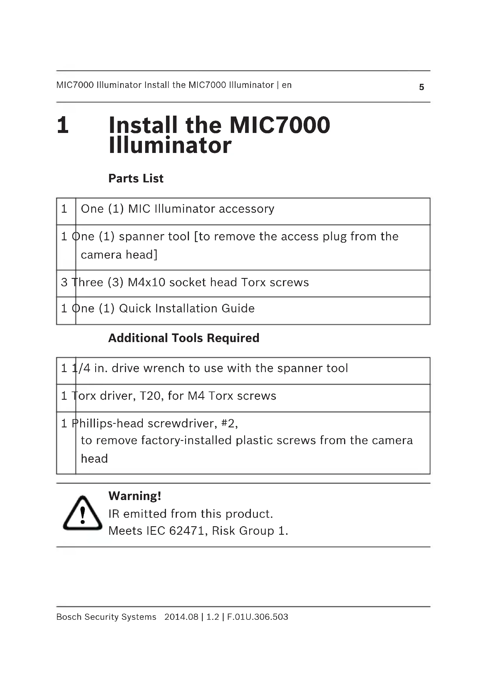
1 Install the MIC7000 Illuminator
Parts List
Additional Tools Required
| 1 | One (1) MIC Illuminator accessory |
| 1 | One (1) spanner tool [to remove the access plug from the camera head] |
| 3 | Three (3) M4x10 socket head Torx screws |
| 1 | One (1) Quick Installation Guide |
| 1 | 1/4 in. drive wrench to use with the spanner tool |
| 1 | Torx driver, T20, for M4 Torx screws |
| 1 | Phillips-head screwdriver, #2, to remove factory-installed plastic screws from the camera head |

Warning!
IR emitted from this product.
Meets IEC 62471, Risk Group 1.
Notice!

This product has been tested according to standard IEC62471:2006 "Photobiological safety of lamps and lamp systems". The product emissions exceed the EXEMPT Group limit for both Retinal Blue Light and Cornea/Lens infrared hazard as defined by IEC 62471:2006. The product was found to meet the Risk Group 1 exposure limits for IR and White LEDs.
Refer to the MIC7000 Operation Manual for complete information on illumination safety.
Notice!

If the MIC camera will have both illuminator and sunshield accessories, install the illuminator first. Extreme low temperature MIC7000 models do not support the illuminator.
- Mount the camera or stand it temporarily in the packaging foam on a stable surface before proceeding. (Refer to the Operation Manual.)
Note: If the camera will be mounted inverted, you must rotate the tilt head before attaching the illuminator. Apply power and connect to your network as illustrated in the figure below.

From the web browser, access the camera's Settings page. Select Advanced > Camera > Installer Menu > Orientation, and then select "Inverted". Click Set to confirm the selection. The camera head will rotate automatically into inverted position (180°).
Regardless of mounting orientation, the visor should always be above the camera window.
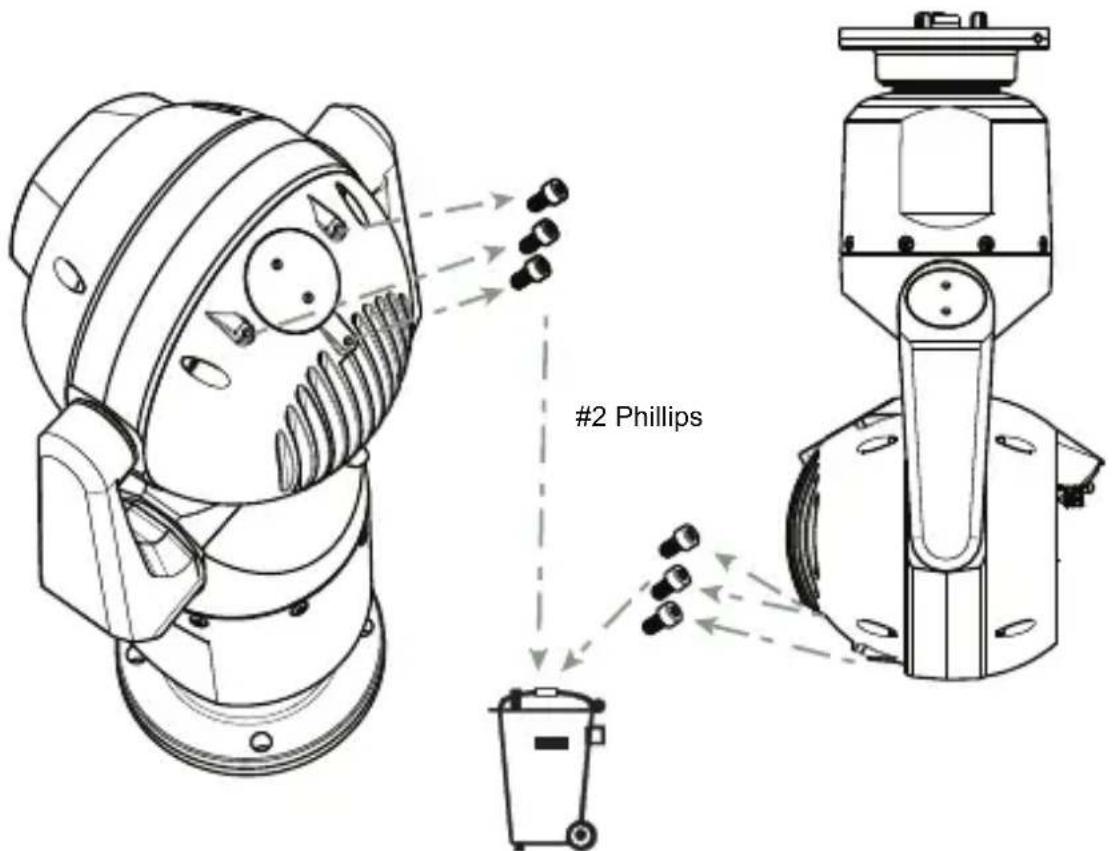
- Remove and discard the three (3) plastic screws surrounding the appropriate access port where the illuminator will be installed.

- Remove the appropriate access plug from the camera head, using a 14 in. drive wrench (not supplied) with the spanner tool (supplied). For upright cameras, remove the plug near the visor. For inverted cameras, remove the plug farther away from the visor.

Notice!
Risk of damage to camera!
Do not allow water or dirt to enter the open connector port.

Bosch suggests storing the access plug and spanner tool inside the DCA mount (or wall mount accessory) in case it becomes necessary to remove the illuminator.
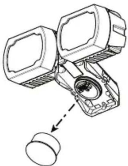
- Remove the plastic cap from the illuminator accessory. Discard.

Notice!
Do not disturb the O-ring as you slide off the cap.

- Align the illuminator over the access port and carefully push into position on the camera head.
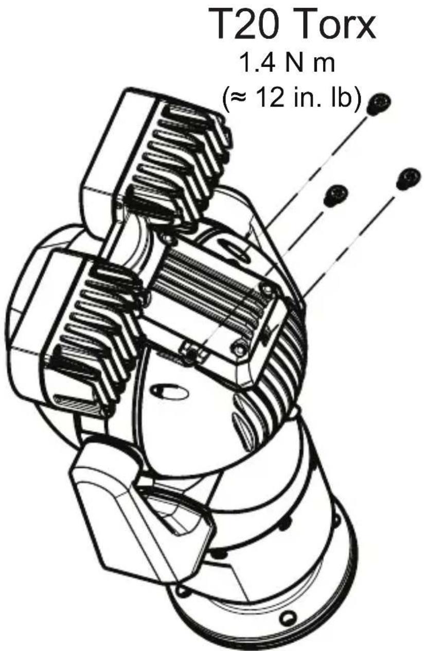
- Partially engage the threads of all three (3) screws. Do not tighten any one screw completely at this point.

Notice!
If you are also planning to install the MIC sunshield, insert only the rear center screw to hold the illuminator accessory in position until you install the sunshield.
Tighten the screw on one side by two (2) turns. Tighten the screw on the other side by two (2) turns. Tighten the center screw by two (2) turns. Repeat until all screws are tight.

Warning!
Total engagement is not complete until you tighten all three (3) screws.

7. Remove the translucent film.


8. Installation of the illuminator is complete.

7. Retirez le film transparent.

CootBcTByeT cTaHdapTy IEC 62471, rpynnpa pncka 1.
3ameuHnI

EcnBbTaKKe PnHaHpyeTe yCTaHOBTb
cOnHcE3aunTHbI K03bipeK MIC, BCTaBbTe TOnbKO
cHTpaHbI BnHT c3aI n dI 3aKpeIeHnI
Uppfyller IEC 62471, Risk Group 1.

Obs!
Bosch Security Systems, Inc.
850 Greenfield Road
Lancaster, PA, 17601
USA
www.boschsecurity.com
© Bosch Security Systems, Inc., 2014


Brand : BOSCH
Model : MIC7000 Illuminator
Category : Surveillance Camera