
VL 5569 LB - Fan AEG - Free user manual and instructions
Find the device manual for free VL 5569 LB AEG in PDF.
| Brand | AEG |
| Model | VL 5569 LB |
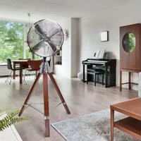
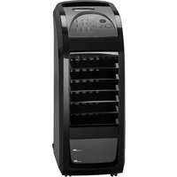
| Product type | Fan with built-in humidifier |
| Power supply | 220-240 V~, 50 Hz |
| Power consumption | 85 W |
| Net weight | 3.60 kg |
| Water tank capacity | Approx. 3 liters |
| Fan speeds | 3 levels: low (LO), medium (MI), high (HI) |
| Ventilation modes | Normal (NOR), Natural (NAT), Sleep (SLE) |
| Timer | Up to 7.5 hours, adjustable in 30-minute increments |
| Oscillation | Yes, range of approx. 60° |
| Humidifier | Ultrasonic, 3 intensity levels (LO, MI, HI) |
| Controls | On the switch housing and remote control |
| Remote control | Range approx. 8 meters, batteries 2 x AAA (not included) |
| LED indicators | POWER and humidity levels |
| Tilt angle | Approx. 10 degrees |
| Grill material | Plastic with mounting hooks |
| Included accessories | Support base, tubes, front and rear grills, fan blade, screws and nuts, remote control |
| Cleaning | Damp cloth for the housing; white vinegar for the tank and base |
| Safety | Protective grill, automatic shut-off in case of tipping (not specified), do not immerse |
Frequently Asked Questions - VL 5569 LB AEG
User questions about VL 5569 LB AEG
0 question about this device. Answer the ones you know or ask your own.
Ask a new question about this device
Download the instructions for your Fan in PDF format for free! Find your manual VL 5569 LB - AEG and take your electronic device back in hand. On this page are published all the documents necessary for the use of your device. VL 5569 LB by AEG.
USER MANUAL VL 5569 LB AEG
Assembly overview Page 4
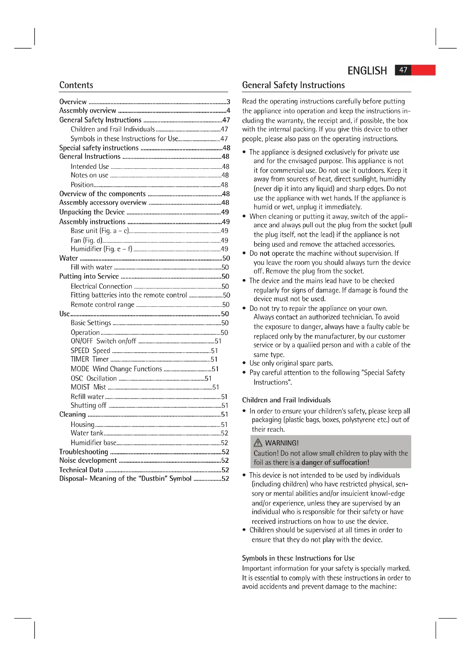
Contents.. 47
Technical Data Page 52
JEZYK POLSKI
Spis tresci
Przeglad. Strona 3
Przegl d monta zu. Strona 4
(piles non fournies)
General Safety Instructions 47
Children and Frail Individuals 47
Symbols in these Instructions for Use. 47
Special safety instructions 48
General Instructions 48
Intended Use 48
Notes on use 48
Position. 48
Overview of the components 48
Assembly accessory overview 48
Unpacking the Device 49
Assembly instructions 49
Base unit (Fig. a-c). 49
Fan (Fig. d) 49
Humidifier (Fig. e - f) 49
Water 50
Fill with water 50
Putting into Service 50
Electrical Connection 50
Fitting batteries into the remote control 50
Remote control range 50
Use 50
Basic Settings 50
Operation 50
ON/OFF Switch on/off 51
SPEED Speed 51
TIMER Timer 51
MODE Wind Change Functions 51
OSC Oscillation 51
MOIST Mist 51
Refill water. 51
Shutting off 51
Cleaning 51
Housing. 51
Water tank. 52
Humidifier base. 52
Troubleshooting 52
Noise development 52
Technical Data 52
Disposal- Meaning of the "Dustbin" Symbol 52
General Safety Instructions
Read the operating instructions carefully before putting the appliance into operation and keep the instructions including the warranty, the receipt and, if possible, the box with the internal packing. If you give this device to other people, please also pass on the operating instructions.
- The appliance is designed exclusively for private use and for the envisaged purpose. This appliance is not it for commercial use. Do not use it outdoors. Keep it away from sources of heat, direct sunlight, humidity (never dip it into any liquid) and sharp edges. Do not use the appliance with wet hands. If the appliance is humid or wet, unplug it immediately.
- When cleaning or putting it away, switch of the appliance and always pull out the plug from the socket (pull the plug itself, not the lead) if the appliance is not being used and remove the attached accessories.
- Do not operate the machine without supervision. If you leave the room you should always turn the device off. Remove the plug from the socket.
- The device and the mains lead have to be checked regularly for signs of damage. If damage is found the device must not be used.
- Do not try to repair the appliance on your own. Always contact an authorized technician. To avoid the exposure to danger, always have a faulty cable be replaced only by the manufacturer, by our customer service or by a qualified person and with a cable of the same type.
- Use only original spare parts.
- Pay careful attention to the following "Special Safety Instructions".
Children and Frail Individuals
- In order to ensure your children's safety, please keep all packaging (plastic bags, boxes, polystyrene etc.) out of their reach.
WARNING!
Caution! Do not allow small children to play with the foil as there is a danger of suffocation!
- This device is not intended to be used by individuals (including children) who have restricted physical, sensory or mental abilities and/or insufficient knowledge and/or experience, unless they are supervised by an individual who is responsible for their safety or have received instructions on how to use the device.
- Children should be supervised at all times in order to ensure that they do not play with the device.
Symbols in these Instructions for Use
Important information for your safety is specially marked. It is essential to comply with these instructions in order to avoid accidents and prevent damage to the machine:

WARNING:
This warns you of dangers to your health and indicates possible injury risks.

CAUTION:
This refers to possible hazards to the machine or other objects.

NOTE:
This highlights tips and information.
Special safety instructions
- Never stick fingers or other objects through the protection grid!
- Watch out for long hair! It can be caught in the fan owing to the air turbulence!
- Use the appliance only with the protection grids on!
The appliance must be assembled completely before use! - Select a stable base to avoid the tipping of the fan during use!
- Do not place the device immediately next to stoves or other sources of heat.

CAUTION:
The integrated humidifier works by ultrasound. This sound may be disturbing to pets.
General Instructions
Intended Use
This appliance can be used as a fan and/or humidifier. It is intended exclusively for this purpose and may only be used as such. It may only be used in the manner described in these instructions for use. The device must not be used for commercial purposes.
Any other use of this device is considered to be contrary to the intended use and may result in damage to materials or even personal injury.
The firm ETV - Elektro-Technische Vertriebsgesellschaft mbH does not accept any liability for damage caused as a result of the use of this device contrary to its intended use.
Notes on use
You can use this appliance to increase the air humidity in a dry environment. This offers the following benefits:
- Provides a healthy indoor environment and is thus beneficial to your well-being.
- Your skin does not dry out as readily.
Static in the air is eliminated.
The appliance works best if doors and windows are kept closed when used in mist mode.
Position
The ideal position is a non-slip, flat surface.
Overview of the components
Overview
1 Hook
2 Fastening hooks
3 Propeller
4 Protection grid
5 Mounting screw M2.5*8mm with nut
6 Switch housing
7 Stand tubes
8 Tube with tank cap
9 Water tank
10 Humidifier base
11 Stand with cover
Assembly overview
12 M518mm screws
13 Base (Base plate)
14 Metal plate with mounting holes
15 M5 nuts
16 Cover of the stand
17 M610mm screws with nuts
18 Motor
19 Rear protection grid
20 Nut for rear protection grid
21 Attachment screw for propeller
22 Front protection grid
Not shown
Remote control
- ST4*25mm screw for fastening the humidifier to the stand
M6 nuts to fasten the motor to the stand tubes
Assembly accessory overview
| Number | Quantity | Accessories Size | |
| 5 1 | Screw M2,5*8mm | ||
| 5 1 | Nut M2,5 | ||
| 12 4 | Screws M5*18mm | ||
| 14 1 | Metal plate | ||
| 15 4 | Nuts M5 | ||
| 17 2 | Screws M6*10mm | ||
| 20 1 | Nut | ||
| 21 | 1 Screw | ||
| None | 1 Screw | ST4*25mm | |
| None | 2 Nuts | M6 |
Unpacking the Device
- Remove the device from its packaging.
- Remove all of the packaging material such as foils, filling material, cable holders and cardboard packaging.
- Check the scope of delivery.

TE:
There may still be dust or production residues on the surface of the device. We recommend that you quickly wipe of the housing with a damp cloth.
Assembly instructions
The appliance must be fully assembled before use! We recommend that you refer to the figures "Overview" and "Assembly overview" when assembling.
Base unit (Fig. a-c)
- Screw the tubes (7) onto the stand (13). Use the four screws (12), the metal plate (14), and the four nuts (15).
- Attach the cover of the stand (16) to the stand tubes.

TE:
The nuts and screws (17) are preinstalled on the rear of the switch housing.
3. Check if the screws (17) possibly have been screwed into deeply. In this case, turn the screws back a little. Do not screw them out all the way!
i NOTE:
If a screw or a bolt should have dropped off, proceed as follows:
- Hold the preassembled unit (motor (18), switch housing (6), and humidifier base (10)) so that the motor points down.
- Insert one nut (M6) each into the shaft at the side of the recesses for the tubes.
-
Screw the two screws (17) on the rear of the switch housing lightly into the nuts.
-
Set the preassembled unit for a depth of approximately 3cm onto the stand tubes.

The humidifier cable must be routed between the two tubes.
Secure the preassembled unit to the stand tubes by tightening the two screws (17).
- Fasten the base of the humidifier (10) with the large screw (ST4*25mm) to the base of the stand. For this, insert the screw from below through the stand and its cover into the small outer bore. (Fig. on the right)

Fan (Fig. d)
- Remove the preinstalled nut (20) from the motor (18). Keep it close to hand.
- Align the rear protection grid (19) with the motor recesses (18).
i NOTE:
The handle must point upwards.
- Tighten the nut (20) for the rear protection grid clockwise.
- Attach the propeller (3). When doing so, use the guide pin on the motor shaft.
- Tighten the screw (21) for the propeller anti-clockwise.
- Remove the prefitted screw and nut (5) from the front protection grid (22). Keep it close to hand.
- Open the fastening hooks (2) at the front protection grid.
- Attach the front protection grid by engaging the groove of the hook (1) with the rear protection grid.
i NOTE:
The holes for the screw (5) in the front and rear protection grid must be aligned.
- Secure the protection grid with the screw and the nut (5).
- Close the four fastening hooks (2).
Humidifier (Fig. e - f)
The tube already may have been installed on the switch housing. In this case, continue the assembly from item 18.
- Feed the tube (8) from front to back between the two stand tubes (7). Then insert the tube from the bottom upwards through the opening on the underside of the switch housing (6).
iNOTE:
The end of the tube with the tank cap must be positioned at the front above the humidifier.
- Insert the tube from the back to the front through the opening on the top of the switch housing.
- Pull the tube tight so that it lies flat against the back of the switch housing.
i NOTE:
The two ends of the tube should have approximately the same length.
- Connect the top end of the tube to the tube connector on the protection grid (22).
i NOTE:
The tube above the switch housing must not "sag". Water which accumulates in the tube prevents the formation of the mist. If necessary, push back the top section of the tube.
- Place the water tank (9) onto the base of the humidifier (10).
ENGLISH
- Fit the tank cap on the bottom end of the tube onto the water tank. The recess on the tank cap must fit into the groove on the opening to the water tank.
i NOTE:
- The tank cap on the end of the tube can be turned.
- The water tank must be fitted securely to the base so that mist cannot escape between the water tank and the base. If necessary tighten the lower section of the tube.
Water
Only use distilled or boiled, cold tap water without additives.
CAUTION:
Do not fill the water tank with water from clothes dryers and water with additives (such as scented oils, perfume, softeners, or other chemicals). Doing so may damage the appliance.
- Replace the water every 3-4 days, even if it has not yet been used.
- If the appliance has not used for long periods, remove the water from the water tank and from the base of the humidifier.
Fill with water
- Pull the end of the tube with the tank cap out of the water tank.
- Lift the tank from the base of the humidifier and turn it over. The filling hole is located on the bottom of the tank.
- Turn the tank cap and fill the water up to ca. 1 centimeter below the rim. The tank holds around 3 litres.
- Close the cap again and place the tank back onto the base.
- Place the end of the tube with the tank cap onto the water tank.
iNOTE:
Take note of the recess on the tank cap (see assembly instruction, item 21).
Putting into Service
Electrical Connection
- Before inserting the plug into the socket. Make sure that the mains voltage to be used matches that of the device. You can find this information on the nameplate.
- Connect the device to a duly installed 230V 50Hz protective contact socket. The indicator lamp POWER shows that the power supply is connected.
Fitting batteries into the remote control
(Batteries not supplied)
- Open the lid of the battery compartment on the rear of the remote control.
- Insert 2 MICRO batteries of type R03 "AAA" 1.5 V.
- Please ensure the correct polarity. Details can be found in the battery compartment.
- Close the battery compartment.
NOTE:
If you are not going to use the remote control for a prolonged period, remove the batteries in order to prevent them from leaking.
CAUTION:
Used batteries should not be disposed of in the domestic waste. Please return all batteries to a special collection point. Your local authority will provide you with information on this.
- Different types of battery or new and used batteries must not be used together.
Remote control range
The remote control has a range of ca. 8 meters. If this range becomes shorter, the batteries must be changed.
To use the remote control, point it at the sensor on the front of the switch housing.
- Make sure there are no obstacles between the remote control and the sensor.
- The angle of the remote control to the remote control sensor should not exceed 30° to the right, left, up, and down.
Use
Basic Settings
Set the blower inclination angle before starting the device. You can adjust the inclination angle by tipping the blower casing with both hands.
NOTE:
- The inclination angle amounts to approx. 10° .
- The tube above the switch housing must not "sag" due to the inclination of the blower. Water which collects in the tube prevents the formation of mist.
Operation
You can operate the appliance using the remote control as well as the buttons on the switch housing. The functions are identical.
i NOTE:
The LED's on the switch housing indicate the settings.
ON/OFF Switch on/off
Use the ON/OFF button to switch the appliance on or off.
NOTE:
- When switching on for the first time after you have connected the mains plug to the mains outlet, the fan works in NOR (normal) mode with a low speed (LO).
- After switching off and on again using the ON/OFF button, the appliance continues working in the last set mode.
SPEED Speed
Press the SPEED button to select one of the three different speeds.
LO low
MI medium
HI high
TIMER Timer
If you want the timer to switch the device off, press the TIMER button.
NOTE:
Every press of the TIMER button increases the operating time by 30 minutes.
Maximum shut-off time: 7.5 hours.
MODE Wind Change Functions
The device has the two special functions: NAT (NATURE) and SLE (SLEEP). The speed of the fan buries between the functions.
Press the MODE button to switch these functions on.
-
NAT Natural Mode
-
If the HI (high speed) setting is selected, the speed alternates between high-medium - low-off.
- If you have selected MI (medium speed), the speed alternates between medium - low - off.
-
In the LO (low speed) setting, the speed alternates between low - off.
-
SLE Sleep Mode
-
If HI speed is set: The fan works in the first 30 minutes as in "Natural Mode" at the HI speed setting. In the subsequent 30 minutes the fan works as in "Natural Mode" at the set MI speed. For the remaining time the fan works as in "Natural Mode" at the speed setting LO.
- If MI speed is set: The fan works for the first 30 minutes as in "Natural Mode" at the speed setting MI. For the remaining time the fan works as in "Natural Mode" at the speed setting LO.
-
If LO speed is set: Switching between low speed and shut-off of the fan as in "Natural Mode".
-
Select the NOR (NORMAL) function to return to normal operation.
OSC Oscillation
- If you select the OSC function the device oscillates automatically through a range of approximately 60 degrees.
- In order to switch the function of, press the OSC button again.
MOIST Mist
The humidifier can be switched on and off regardless of the fan mode.
Press the MOIST button to select the intensity of the mist:
LO low
MI medium
HI high
- To deactivate the function, press the MOIST button again.
Refill water
When you want to refill the tank:
- Switch off the appliance.
- Disconnect the plug from the mains.
- If necessary, pour the remaining water out of the tank.
- Proceed as described under "Fill with water".
Shutting off
If you want to shut off the fan:
- Switch off the appliance.
- Disconnect the plug from the mains.
- Empty the water tank and the base of the humidifier if you do not plan to use the appliance for a lengthy period.
Cleaning
WARNING:
Always remove the mains plug before cleaning the device.
- If you need to remove the protection grid: Always switch the device of and remove the mains plug.
- Under no circumstances should you immerse the device in water for cleaning purposes. Otherwise this might result in an electric shock or fire.
CAUTION:
- Do not use a wire brush or any abrasive items.
- Do not use any acidic or abrasive detergents.
Housing
- Clean the outside of the device with a dry cloth without any additives.
- If the device is very dirty wet a cloth with water and then wipe the device dry once you have inished.
Water tank
- Rinse the tank with clean water.
- Allow the tank to dry before closing it again.
- If the tank is very dirty, add ca. 100ml of white vinegar to the cleaning water.
- Leave the solution in the tank for ca. 10 minutes.
- Rinse out the water tank with clean water.
Humidifier base
- Clean the area on which the water tank rests once a week.
- Wipe the area with a damp cloth.
If necessary, use a few drops of white vinegar and let it act for ca. 5 minutes. - Then wipe the area clean again.
- Stubborn dirt can be loosened with a nylon brush.
Troubleshooting
| Problem Cause Solution | ||
| Appliance does not work. | No power supply Check the mains outlet. | |
| Defective electronics | Seek advice from a dealer or service centre. | |
| The POWER LED and one of the MOIST LED's (LO/MI/HI) are lit, but no mist is being produced. | The water tank is empty. | Fill the water tank. |
| Not enough mist is being produced. | Water has collected in the tube underneath the switch housing | Push the top section of the tube back so that the water cannot accumulate. |
| The humidifier is dirty. | Clean the humidifier. | |
| The water is dirty. Change the water. | ||
| Mist or water escapes between the water tank and the humidifier base. | The bottom section of the tube is too short. | Pull back the bottom section of the tube so that the water tank fits securely on the base. |
| There is a bad smell. | The water is too old or dirty. | Change the water and clean the humidifier. |
Noise development
The workplace-related emission value is less than 70 dB(A).
Technical Data
Model: VL 5569 LB
Power supply: 220-240 V\~, 50 Hz
Power consumption: 85 W
Protection class:
Net weight: 3.60 kg
Subject to technical changes without prior notice!
This device has been tested according to all relevant current CE guidelines, such as electromagnetic compatibility and low voltage directives, and has been constructed in accordance with the latest safety regulations.

Disposal- Meaning of the "Dustbin" Symbol
Protect our environment: do not dispose of electrical equipment in the domestic waste.
Please return any electrical equipment that you will no longer use to the collection points provided for their disposal.
This helps avoid the potential effects of incorrect disposal on the environment and human health.
This will contribute to the recycling and other forms of reutilisation of electrical and electronic equipment.
Information concerning where the equipment can be disposed of can be obtained from your local authority.
Spis tresci
Przeglad 3
Przeglad montazu 4
Wentylator (Rys. d) 55
Nawilacz (Rys. e - f) 55
Woda 56
Nalewanie wody. 56
Uruchomienie 56
BentnTOp (MaI. d) 68
3BoloxyBaay (MaI.e-f) 68
Boda 69
HANOBHeHHBOdoHO 69
BBeHeHH Beknnyatauio 69
EeKtpnue nikloueHHra. 69
BctaHOBnEHH6bTapeyynbTdNCTaHcHOrO
KepyBaHHa 69
DianaoHdi npbTa duCTaHuiHoro KepyBaHH 69
BukopncTaHH 69
Ba30bi hactpoobahnra 69
Bukopustahna 69
ON/OFF YbIMKHeHHBbIMKHeHH 69
SPEED 70
TIMER TaMep 70
MODE ΦyHKU3mHn NOBITpHoro NOTOKY 70
OSC Oocuiia 70
MOIST Imla 70
Доadingи.. 70
BumkHeHH 70
OuHueHH 70
Kopnyc. 70
Pe3epByap nIy BODI 70
Ochoba 3BOLOKyBaay 70
UcyHenHHehCnpaBHOCTe 71
Texhihi napametph 71
3araIbHI Bka3IBKN 10oDo 6e3neKn
Ipeep npinHnTAM B ekCnnyatauio zuoro npnaady dyjke yBaXHO nHTaTe IHCTpyKUIO 3 ekCnnyatauii Ta 36epiraiTe ii pa3OM 3 rapaHTiINHM TanoHOM, KACOBIM YekOM Ta, no Mipi MoKInBOcTI, 3 KAPTOHHO KOPO6KOIO i BHYTpIHbOIO ynakOBkoIO. Y pa3i, 0o npnaad bye nepedaHO TpeTIMOCobam, cnid nepedabatni horo pa3OM 3 ueio IHCTpyKUio 3 ekCnnyatauii.
BnKOpNCTaTe npnIaD BnKIOUHO B npBaTHx LiJx Ta 3a npeI6baeHm np3HaueHHM. PpnaIa He np3Ha- yEHO IINPOMNCIOBOrO BnKOpNCTaHH.
He BnKOpncTObyIte Horo Ha Bynnu. ObepiraTe Horo BiD CNEKN, PnAMORO COHrHOrO ONpOMIHOBaHHB, BOIOn (B KODHomy pa3i He OnyckaTe y pINHy) Ta roCTpxk KyTB. He KopNcTByTEcA npInaDM 3 BOIOnMM pyKaMn. Rkuo npnad 3BOLOXHBc a60 3MOkpIB, HeBiKnADHO BuTARHITb UTENCeJIbHy BNky.
BIMKHTb npnlaT a 06OB'3KOBO BNTHHTb BNky 3 WTeNCEbHOI PO3ETKN (TtHHTb 3a WTeKeP, He 3a Ka6eNb), KOJI Hc KOpNCyTeCb npnlaDM, abo MOHTyeKOMnEKTyoHi DeTani, abo Niac uuueHHa 60 npn deΦeKtax.
Heeknyte npna6e3 orny.ObOB3KOBO BmKHTb npna, KOJI BN NOKndaTe PnMIueHHa.
BntarHitb utencelHy Bnky 3 utencelbhoi po3eTK.
Perynpho npebiprTe npnaT a Kaebb Ha no- shkoDkeHH. NooKOJKeHn npnaI He cnId nyckaTn B ekcnlyataiuio.
He pemontyte npnna cami, ane 3BepHtbcra do aTbOpn3oBaHoro faxibua. Ia 3ano6iraHH 3arpo3i noKdoKeHH Ka6eJIb KJIBneHH CIId 3amHHTn Ha eKBiBaIeHTHn BKNIOUHO BINO6HnKOM, a60 HsOc cepBicHO cnyk6oio a60 iHoo KBaIipikOBaHO Oco6oIO.
KopnctyTEcBnKIOHOOpnIHbHMN KOMnEeTByBaHmN DetanrMn.
3BepHITb ybarhy Ha hAcTynHi "CneuiabHi Bka3iBkn 10do6e3neKn
DITNa HEMiHi OcO6n
Дябзнсвixдг He 3aJnuaite DoCTyHIMn nakybanbHi MaTepiAn (ПлactNKOBi NaKETN, KapTOHHI Kopo6Kn, NeHONlact TToO.

NONEPENKEHH
He Do3B0nHte MaHMM dITAM rpaTncb i3 pNNBKOIO. IcHyE 3arpo3a3ayxN!
Ley npnla He npnaeHm IIN BHKOpCTaHHIIObMn (BKNIOUaOuN dTei) 3 OMeKeHMM fI3NUHMn, yTTEBHMn a6o PO3yMOBHMn 3dIOHOCTHMn, HEoCTaTHIM DOCBIDOM Ta/a6o 3HaHHMa - KpIM BNanIKIB, KOJIN 3a HMM DoJIraAc BiINObiaJaBHa 3a iX 6e3neky OC6a a6o BOH OTPMaHn BkA3IBKn 5IO DO BHKOpCTaHHI npnaNy.
- DITM He Do3BoneHO rpaTncb 3 cH M npHaDOM. NOTPI6eH DOrJa3a HmN.
PnDaTHM Micem DnPa PO3TaUyBaHH E NOIora HeKOB3Ka NOBepxH.
Детаиnpладу
3aŋbnyo
1 RaK
2 Kpiinnbni rak
3Пponenep
4 3axncha pewitrka
5ΓBnHTdIaMOHTyBaHHM2,5*8MM3raKoO
6 NaHEnb nepemikauib
7 Tpy6kn nictdtabkn
8 Tpy6ka 3 kpiuKIO pe3epByapa
9 Pe3epByap DJIY BOIN
10 OchOBa 3BOJIOKyBaay
11IiDcTaBka3KpuiuKOHO
CxemaMOHTyBaHHA
12 ΓΒΗΝΤΗ M518MM
13 CToRk (OCHOBA)
14 MetaneBa nIHTa 3 OTBopamn Ia MoHTyBaHHa
15 Raikn M5
16 Kpnska nidaTbKn
17 TbHTM M610MM i3 raHkamn
18ДВИRGYH
19 3aHnHa 3anobixHa peuitka
20 Taina TINbHOCTOPOH3axHCHOI peWitK
21 KpinnbHn rBnT dnn nponepea
22 PpeDnHa 3anobixkha pewiitka
Be3 306paXeHH
- DnctaHuiHe ynpabInHH
ΓBHT ST4*25MMДЯКрпнеленя 3БОЛОЖуВачdoNiD-CTaBKN - Raik M6 Дя Крплесьд Виуна Do Tpybok NiДctaBkn
OrnI npHaIaIg IJI MOHTyBaHHA
| Homer KIbkiCTb Prn haДя Po3mip | |
| 51 ГВИНТ M2,5*8MM | |
| 51 ГВИКа M2,5 | |
| 124 ГВИNTN | M5*18MM |
| 141 Металева ппita | |
| 154 ГВИКИ M5 | |
| 172 ГВИNTN | M6*10MM |
| 20 | 1 ГВИКa |
| 21 | 1 ГВИNT |
| Hemac | 1 ГВИNT ST4*25MM |
| Hemac | 2 ГВИК M6 |
P03nakyBaHH npHlaNy
IocTaHbTe npnna3 ynaKOBKn.
- Ucyhbe Bci nakyBaJIbHi MaTePIaIi NK IIIBK, MaTePIaIi-3anOBHIOBaUi, Ka6eJIbHi CKOb Ta KapTOHHy ynaKOBky.
- IpebeipTe KOMnIeKTHiCtB.
IINPMITKA.
Ha npinady MoKytb 6ytn nn a6o Bnpo6HnHi 3aHHK. PekomeHaiai BnInpatn Kopnyc 3BoloxKeHO raHypkoIO.
Ihctpykci3 MOHTaKy
Ipeew hix BMnKaTH npNCTpii, noro cnID NOBHCIO 3MOHTyBaTH! LIOo MOHTyBaHH npNCTpoIO DnIBITbcra MaHONKIN "3araJbHn orJa" i "Cxema MOHTyBaHH".
CTiHa (MaJ.a-c)
(BaataeKn He BxOaTb Do KOMnIeKTy nOCTaHaHH.)
BidkpBaIte KpUkry rH3da dIe IeMeHTIB XKMBHeHHHa 3BOPOTHomO bOui pIyIbTa dNCTaHcHIO KepyBaHHA.
- Pokladitb 2 mikpoobatapekn Tnny R03 "AAA"1,5 B.
3BaXte Ha Bipy noJnRpHcIb! DeaBHiue dNbiTbcB KzaibKy y BiCiKy dJa 6atapei.
3aKpBaIe THi3O dIe IeMeHTiB JxHbIeHHa.
TPIMITKA.
KoJn Bn DOBRO He KopnCTyeTecra NylbTom dNCTaHuiHORO KepyBaHHa, BmIMt b 6atapeeKn dna 3anobiraHHa BNTiKaHHa 6atapeeHOI KNCLOTN.
yB4A.
BiiDnpaubobahi 6batapeKHe cnid BiDdAanr3 noobyTOBIM CMITTM. BiHecitb 6batapeKn Do ophiHoro nyHKTy 360py. IHOpMaioo loo Hx Bam Hadaotb 3a Micem npokBaHHa
He moXHa BnKOpNCTOByBaTH p3Hi TnHb 6aTapeNOK a6o pa3OM HOBI Ta BnKOpNCTaHI 6aTapeKN.
Diana30H dIyNbTa dNCTaHuiHoro KepyBaHH
Iiana3OH dI nyIbTa nCTaHuiHoro KepyBaHHra - npN6Jn3HO 8 M. JIkuo dIana3OH dI CKOpOTBcR, bataei cnid 3amHHTn.
LIO6KOpNCTyBaTnCnIyBtOMINCTaHcHOrOKepyBaHHaHBeDiTbNoHaCEHCOPcpepeHyHaNaHEni nepemikauiv.
- YneBHITbcra, IIO mix NylbTom i ceHCOPOM Hemae nepeIHKoD.
Kyt haxiny nybTa dinCTaHIOrO KepyBaHH BIDHOcHcEHCopa He Mae npeBnUyBaTH 30° npabOpuy, NiBOpyu, Bropy i BnI3.
BnKOpncTaHH
Ba30Bi HAcTpOBoHHA
Pepd nycOM B eKcnnyatauio BcTaHOBitb KyT haxnByeHTnIATopy.Bm MoKeTe BcTaHOBNIoBaTH Kyt HaxnTy B 6aJxHaii no3ni TMM, 0o nepeKnDaTe KopNc BeHTnIATopy DBOMa pyKaMn.
IIPMHITKA.
Kyt haxiny cknlaaep npn6n3no 10 rpayncib.
Tpyka naHnennno nepemikauib He nobHHa "nporHaTncb" y pazi haxiny BeHTnIHTopa. Boda, zo haKoNHyETbcra B ty6ci, 3ano6irae yTBOpEHIO poch.
BHKOPNCaHH
Pnctpoem MoKHa ynpaBnTn 3a DonomoroH npbTa nCTaHnHO KepyBaHH i KhoNOK Ha naHeni nepemKaHIB. BOHN BkOHHyIb OndaKObi FyHKii.
IIPMITKA.
CbitnoioiDHH iHnKaTOp Ha naHeni nepemnkaiv Bkazc HbBpaHHaanuTyBaHH.
ON/OFF YbIMKHeHHBIMKHeHH
KhoNka ON/OFF dae 3Mory yBIMKHHTn IBIMKHHTn npnctpi.
IIPMITKA.
- Y pa3i yBIMKHeHH Bneppe nicra niKnHouEHn Do MepeKi BEHTnIaTOp npauoE y peKmI NOR (hopMaIbHn) i3 Hn3bKOHO WnDkictIO (LO).
Псгь ВIMKHeHHI yBIMKHeHHa 3a DOonomoROIO KHONK ON/OFF npncpti npaOBOATME B OCTaHHbOMy BCTaHOBJIeHOMy peKmI.
SPEEDIIBnDkicTb
HaTnCHiB KnaBiuy SPEED IaI Bn6Opy OndHoro 3 Tpbox CTyneHIB WbNdkoCTi.
LO Hn3bKa
MI cepednra
HI BncoKa
TIMER TaMep
HaTNCiB KJIaBiU TY TIMER, KOJI N XOyTe BIMNKaTI npHlaD 3 nOrODHHM KepyBaHHM.
IPIIMITKA.
3 KOxHMM HaTNCHeHHa KaJIaBiUy TIMER qac po60Tu 36IbIbUyETbcra Ha NiBroDnH.
MaKcImaJIbHn Yac Do BmMKeHHa:7,5rOd.
MODE ΦyHKu3MiHn NOBITpHoro nToK
Ppnaad Mae dei cneuaianbi fyHKui: NAT (NATURE) i SLE (SLEEP). KInbKiCTb o6eptIB BeHTnIaTopy no uX Dbox fyHKiax BapioeTbcra no p3HOMy.
HaTnCHITb KlaBiIy MODE dIy yBIMKHeHHa IxΦyHKui.
NAT PnpoDnH peKm
-ⅠKIO Bn6pHaHO HanaWtYBaHHa HI (BnCOKa WbNkICTb), WBnDKICTb 3MmHOBaTHMeTbCR TaHIM YHOM: BnCOKA-CepeHr-Hn3bKa-BMk.
- 阿卡图 BИбрано nyнг MT (cepeнг WbINKicTB), WbINKICTb 3MInHOBaTmETbCRA TAK: cepeHn - Hn3bKa-BIMK.
- Y peKIMI LO (Hn3bKa LwBnDkiCTb) WbNdkiCTb 3mHOBaTHMETbCra TAK: Hn3bKa - BNMK.
SLE PeknM CHY
AkuoBcTaHOHO WbHkictb HI:BeHTnIaTOp npaIOBaTMe nep30 XB.y "npnpOHOmy peKIMi" 3 BnCOKO IO bNdkicTIO.HactynHI 30 XB.BeHTnIaTOp npaIOBaTMe y "npnpOHOmy peKIMi" 3I WBNDKCTHO MI.PeHTy cacy BeHTnIaTOp npaIOBaTMe y "npnpOHOmy peKIMi" 3I WBNDKCTHO LO.
HKUO BCTAHOBHeo WbHKnICTb MI:BeHTnIaTOp npa- 10EBAITME nepu30 XB.y "npHPOdHOMy peKIMi"3i WbHKnICTo MI.PeWtYu cacy BeHTnIaTOp npauHObATM E y "npHPOdHOMy peKIMi"3i WbHKnicto LO.
Kkuo BCTaHOBNEHO WbNdkictb LO: BnKOHyBaHTMetbcr nepemkaHHa Mx H3bkoU WbNdkiCtIO IBMKKHeHHAM BeHTnIATOpay "PnpOHOmypeKMNI"
Bn6epiB cyHkuio NOR (NORMAL), nla noBepHeHHa Do HopMaIbHo peKmMy.
OSC Ocunna
KoHn Bn oBpaete FyHKiO OSC, npnaIc amoctiHo NOBepTaEcB Diana3Oni np6Jn3Ho 60 rpaucib.
ДяВИМКHEHЯ UIeI ΦYHKUII NOBTOPO HAITCHITb KnaBI-у OSC.
MOIST Imna
3BONOxyBaHMOKHa yBIMKHHTn i BUMKHHTn He3aJIeXHO BiD peKmMy BeHTnIATopa.
HaTnCHiB KhoNkY MOIST, 0o6 Bn6paTn pIbeHb BOJOrn:
LO HN3bKn
MI cepeHi
HI BUCOKNI
LIOB BIMKHyTN FyHKUHO, HATNCHTb KHONKY MOIST pa3.
DoaBaHnBODN
LIO6doaTHBOy
BIMKHTb npncpti.
Bid'cHaIte uTekep Ka6eHIO HINBHeHHa BID po3ETK.
- RaKuo notpioHO, BnHnTe peuTy BOuN 3 pe3epByapa.
Bukohai Te iipo3iny HAnOBHeHHBOdoHO
BmKHeHH
LIO6BIMKHYTNBEHTNITTOP
BIMKHTb npucpii.
Bid'cHaTe WTEKepe Ka6eHIO XKbIeHHa BiD po3eTKn.
CnpoKnHb pe3epByap nB OBDIOOCHOBy 3BOJOKyBaHa, kUO He INaHyETe BHKOpNCTOByBaTN pNCTpiI DOBUn Yac.
OuHueHH

NONEPENKHEHHA.
IpeoHcHmIXHnM OcnyBbHH3aBHN BnTnHtB NkY 3po3eKn.
KoN Bu yCyBaCe 3axnchy peWitKy: 3aBKn BmKn KaIe npnaI aBTHHITb BNky 3 po3eKn.
B JIOHOMy pa3i He onyckai Te npnla dIg OuyueHH B BOy. Lc MoKe npBe3TN Do ydApy cTpyMOM a6o DO nOxekn.

YBAGA.
He BnKOpNCToBMyTe npoTHOi uTKn a6o iHux abpa3NBHX npeMmTiB.
He BnKOpNCTOByIe roCTpNx a6o abpa3nBnX 3ac06iB DnA OuHcEHHa.
Kopnyc
BHTnpaIte npnna330BHi cyxho raHupko,6e3do- daTKOBnx 3acO6iB.
- PnCnJIbHIOMy 3acMieHHI MOXHa 3JIeRka 3BOJIOKHTn raHupKy.
Pe3epByap nla BOH
CnoIocHtB pe3epByap HnCTOHO BDOIO.
JaTe pe3epByapy BnCOxHyTH, nepH HiK 3HOBy 3aKnTn.
HkopeepByapHaTo6pydHn,doaTe Do YnctOIBo100Mn6iIoroOtu.
3aHHTe po3Hn y pe3epByapi np6n. Ha 10 XB.
Cnonochitbpe3epByapuHCTOBOdoIO.
Ochoba 3BONOxyBaHa
- YnCTHTe OCHOBY 3B0JIOKByBaHa OINH paHa TnKKeHb.
- PpOtpaIte OCHOBY BOLOrOIO raHUpkoIO.
- RaHIO notpiioHO, BnKOpHCTaHTe KInbKa Kpanel b 6iNoro OtuI 3aJIuTe Ha 5 XB.
ToDi BntpItb HauHcT0.
CtiiKm6pyMDMOxHa yCyHyTN 3a DonOMOrOHeHNOHO BOI uITKn.
UcyHeHH HeCnPaBHOcTei
| Hecnpabnictb Пучна Виришени | |
| Пристрип не пра-цюe. | Вidсуне Хинь-лени. |
| Дeфekt селк- trponiku. | |
| Свитlandoдни и- дникатор POWER i одир 3 ind尼克аторIB MOIST (LO/MI/ HI) свитяры,鉴定 BOLOGA He pro- дукустя. | Рezервуар дли BOДи поожни. |
| Пр overdукустя не- достаимь BOLOГ. | ВODa 3i6panacry у trубци niid паненьто пere- мінkaчів. |
| Звolyожьач Будни. | |
| ВODa 6prudna. Пс. | |
| ВолORA чи BOda витika€ 3 pezeр- Byupa i ochobni 3вolyожьача. | Нжня секця Trубки нато коротka. |
| ЧутNi Нөрпүмний зanax. | ВODa нато сда- paabo 6prudna. |
TexhiHi napameTpH
MoeIb: VL 5569 LB
Поданьжвмень: 220-240B\~,50T
CnoKnBaHHn noTyXHocTi: 85 Bt
Irgyna eNeKtpo6e3neuHocti:
Bara HETTO: 3,60 K
3aHuaMo 3a cObO npaBO HaTexHiHi 3miH!
Ley npnna 6yno nepebipeho 3riHNO BCix BiIDNbiHnx, aKtyaIbHnx dIpeKTHB CE, HapnknaI duOo eJeKtpomarHHTHO cymicHOCTI Ta H3bKOBOJbTHOI dIpeKTHBN, Ta 36ydoBaHO 3 a HOBITIMN NOLOKeHHMm TexHIk6e3neKn.
CopepkHne
O6uhe cBeJeHn 3
C6opKa 4
O6uhe yka3aHn no TexHnke 6e3oNaChocTh 72
TeHn Hnua HykdaohueceB npncmOTpe 72
CIMBOBJI pRMeHReMbIe B DaHHOM pyKOBoDCTBe NOJIb3OBATeTn 73
CneuaJIbHbIe yKa3aHnNo TeXHKe 6e3OnaChOCTn73
06uhe yka3aHn7 73
HcnoIb3ObaHne no Ha3HaueHIO 73
3ameaHnno nncnoB3OBAHHo 73
Mectonolokhenepn6opa 73
O63op dTeanepn6opa 73
TeaH dH c6OpKn 73
PacnaKOBka npHbopa 74
Hnctpykun no c6opke 74
Onopa (Pnc.a-c) 74
BentnIaTOp (Pnc. d) 74
YbnaKnHntB(Pnc.e-f) 74
Boda 75
HanoJIHeHHe EMKocTn BOIOI 75
IoprotoBka npnbopa K pa6ote 75
IoiKJIIOUeHne K 3JIeKTPocetn .75
Bctabka 6atapeek B npblr DY .75
PaHnyc DeiCTBnIyIbTa DY 75
Ponb3oBaHne npH6Opom 75
Iodrotobutehnapeynpobka 75
YnpabJIeHne 75
ON/OFF BkHoueHne/BbKHOueHne 75
SPEED CkopocTb 76
TIMER TaMep 76
MODE PeKIMbl CMeHb BeTpa 76
OSC H3MeHeHne HaPaBHeHn..76
MOIST YBaXHeHne 76
IonoHHe Hne EMKocTn BODon 76
Ppekpaenne paobbl. 76
YHCTKa 76
Koxyx 76
EMKoCTbIaBBOdbI 77
Kopnyc yBnaKHHreIa 77
UctpaHHeH HeHCnPaBHOcte 77
Texnueckne daHHbie 77
06uye yka3aHnno TeXnke 6e3oNaChOCTN
Ipeed hauanom 3Kcnnyataun npnbopa BnHmataelbHo npouHTaTe npnlaeraemyIO nHCTpykuuHO no 3Kcnnyataun COxpaHNTe ee B HadeXHM MeCTe, BMeCTe C rapaHTnHBIM TaHOOM, KaccOBbIM YekOM N, NO BO3MOXHOCTN, KAPTOH Ho KopobKOc ynaKOBOHyBM MaepnAOnM. EcIn daete KOMy-1n6o nonlon30BaTcR npnbopom, O8ra3ateLbHO daTe BnPnDauy daHHYIO nHCTpykuuHO no 3Kcnnyataun.
Пользутесь пибором тольк частным орразим И по наз ha3haeHHIO. Пибор He npedha3haeHДЯ КOMМерчecKOrO Испьзван.He nolb3yTeCb пибор mID OTKpbITbIM He6OM.
PpeoopaHnTe npbOp OT kapbl, npMbIX COJIHeuHbIX LyueB, BlaJHHocTn (HN B KOem Cnyuae He norgpykaTe erO B Ody) u yapOB o6 octpIe yrIb. He npKacai-Tecb K npbOpBy BnaJHHbIMn pykAmN. Ecnn npbOp yBlaJHHnCra Hn HaMOK, TyT Je BbIHbTe BnIKy N3 po3eTKn.
Iocne 3Kcnpnyataun,MOHTaKe npHnAeNkHOCTe, HCTKE HIN NONOMKe np6Opa Bcerda BbHMaTe BUNKy H3 p03ETKN (TAHNTe 3a BNky,a He 3a KaBeB).
He octabnIte BkIOUeHbIe 3JIeKTPoPnp6OpBb63 npncMOTpa.BbIXOaN3 NOMEUeHbN BcERda BbIKIOu- aTne np6Op.BbHbTe uTEKeP n3 pO3ETKn.
Pnpop nKaBeBcTeBOrO HnTaHnHeo6xOIMOppepyrphO 06CneIOBaTb Ha HAnuHc CNeOB NOBpeKDeHH. Pn OHaPyKeHH NOBpeKDeHH NOnb3OBaTbCn np6opom 3anpeJureTcR.
HnB KOem Cnyae He pemOnHTpyte np6op camocToTReIbHO, a ObaPauAaTeCb B TaKOM CNYae 3a NOMOUsbIO K CneuaNtCY, HMeIOUeMy COOTBeTCTByUOuIN DOnyCK.
H3 coo6paKeHH 6eONacHOCTN, 3aMeHa cTeBOrO
UHypa Ha paBHOaHbI dOnyCKaEcTc TOnbKO Upe3
3aBOIN3ROTOBNTeH, HAUY CEpBNCHyO MaCTepCKyU
IIIN COOTBeTCTBYUOe KBAJIHΦHUNPOBaHOrO CNEuJInCTA.
Icnonb3yIe ToJIbKO OpINHaJIbHbIe 3aNactn.
- PtoKaanyIcTa, co6JIOnaIaTe HnKeCleJeUOJIe "Cneun aIbHbIe yKa3aHINr no TEXHKe 6e3OnaCHOCTN".
TeHn Hnua HykaaOnneC B npncmOTpe
13 coo6paKeHn 6e3oNaChOCTn dIaTe He ocTabJIrTe IeKaTb ynaKOBky (PiactIKOBbIe MeUKN, KapTOH, neHONlact N.T.D.) 6e3 npcMOTpa.

PENyPENKDEHNE!
He no3BONHnTe DeTm nIpaTb C noNtneHOBOI nIeKo. OnachocTb ydyuBa!
OTnp60pHe npedHa3haueHnIINb3OBAHnIiuaMn(BKIOUoayITe)COrpaHneHHbIMNΦN3ueCKHM,CEHCOPHBIMNIIYmCTBEHHbIMCNIOOCBOHCTMnIINIiamaH,HE IMeHOUMM ONbTAHIIHNOxOIMbIX3HaHNI.IVckIOuHHe COCTaBIAKTcuyan,KOrdaOHNHaxODTcnoPNCMOTpOMnIua,OTBETCTBEHHORO 3aNX6e3ONaCHOCTb,NIIKNORaOT3TOIINaONyueHbIyKa3aHnIIOIb3OBaHIOp6Opom.
Heo6xOAnMo npncMatpnbTa 3a DetbMn, YTO6b y6eDHTbCBA TOM, YTO OHN He HrpaHOT C pnp6Opom.
CNMBONI pnpmeHReMbE B daHHOM pyKOBOIDCTBe NOJB3OBaTeJRA
BaHHbIe peKOMeHdauuINI OBeCneueHnBaWSei 630NaChOCTN 0o3HaueHbI NOOCoEHHomy.ObaTeJIbHO CJeMyTe 3TNM peKOMeHdaunm, YToBb IpeOTBpaNTb HecuaTbI clyaHnn NOnOMky n3dJIIn:

IPDEyIpyKJDEHNE:
PpeynpeKdaet 60 onaCHOCTn IIN 3IOPOBbN BO3MOHOM pncke nOlyeHn TpaBMbl.

BHIMAHHE:
Yka3bIbAeT Ha BO3MOKHyIO ONaCHOCTb IIN3DeJIINa INdpyTHX OKpyKaIOUIN NpeDMETOB.

TPMMEUHAHA:
B KaueCTBe MeCToIOnIOKeHnI np6opa roIITc HecKoJIb3-KaIPOBHaN NOBepXHOCTb.
O63op DeTanei npn6opa
O6nne cBeeHn
1 Cko6a
2 KpeenKnHbKnPkoK
3 Ppoeep
4 3aunthar peweTka
5 MoTAtKbI BnHT M2,5*8MM Craikoi
6 Koxyx npeknHouaTeHa
7 Tpy6kN dIa CToiKn
8 Tpyka c hacaikoi
9 EMKOCtB DJI BODJI
10 Kopnyc yBnaJHHnTeJIa
11POnCTaBcKpbIuKo
C6opka
12 BnHTbM5*18MM
13 Pocstabka (Onopa)
14MetaJIINueckaIIATCNHa CMOHTAHHbIMNOTBepCTHnMI
15 Raikn M5
16 KOnyX cToiKn
17 BnHbM6*10MMcraKaMa
18 MoTOp
193aHra 3aunTHa ceTka
20 RaKn dJa 3aHne peWetKn BeHTnIaTopa
21 Kpenexhny 60nt dna nponeeepa
22 PeredHra 3aunTHa cetka
Bespnycnka
IyIbT dNCTaHcUHOHHoY npBaJIeHnA
BnHT ST4*25MM dIg KpeIeHnY yBaJHHTeJI K cToIKe
- RaKnM6 nIg KpeHHeHH dBnIaTeHaK Tpy6kam CTOnKn.
TeTaNn nA c6opKn
| Homep VoluchestBo De TaJIb Pa3Mep | |||
| 51ВИNT M2,5*8MM | |||
| 51Гaɪka | M2,5 | ||
| 12 | 4 | ВИNTы | M5*18MM |
| 14 | 1 | Металическа пл actина | |
| 15 | 4 Гайки | M5 | |
| 17 | 2 | ВИNTы | M6*10MM |
| 20 | 1 Гайka | ||
| 21 | 1 ВИNT | ||
| НET | 1 ВИNT $T4*25MM | ||
| НET | 2 Гайки | M6 | |
PacnaKOBHa npH6opa
- BbInbTe np6Op n3 ynaKOBKn.
- YdaIne BeCb 6e3 NCKIOUChENy yNaKOBOHyB MATEpHa, HApnMpEep, PIIeHky, 3aONHRAOUIM MATEpHaI, DePkaTeJIb KaBeIa N KAPTOHHyO yNaKOBky.
PpOBepeKOMJIeKTHOCTbIOCTaBKn.
ПИМЕЧАЙ:
Pnp6op MoKet 6bItb NOKpbT nbInbH nIN octaTkAmn npOu3BOdCTBa. Mbl peKOMeHnyem Bam cnerKa npotepeTb Kopnyc BnaXKnOH TprKnKo.
Hnctpykunno c6opke
Ipeed TEM, kak BkHouaTb yCTpoNTCBO, OHO DOJNHO 6bltb noHocTbO cObaHo! Pn C6opKe peKOMeHdyETcB OcNoIb30BaTbca pncyHKam "O6uue CbeDeHna" n "C6opKa".
Onopa (Pnc. a-c)
1.ПиИВИNTIte Tpy6Kn (7)К CTоIKe (13).ИспοЛБ3уITE chTbpe BnHTa (12),MetaJIINueckyIO ПlaCTInHy (14)И chTbpe raIKN (15).
2.Пикpenite KoKHyx cToiKn (16)КТубКam cToiKn.
ПРИМЕЧАЙ:
TaiN 60ntb1 (17) yke yctahOBHeHbHa 3aDne naHeN KOxyxa nepeKnHouateJIa.
3.Поверьт,чбыВИNTы(17)He6blINBBHUYeHb CnIuKOMrIy6koB.B3TOMcIyuaeOTBHTInTeHX HeMHOROHa3aI.He BbIBUNBaIte nx noJIHOCTbIO!
ПИМЕЧАНО:
EcnBnHTnn6oT cnyaHb BbIaI, HxKHO cIeIaT bCleDyUOJIee:
Bo3bMITE npedBapntelHo c6paHbI 6nok (DbirateIb (18), koxynepeKIOUaTeIa (6) n Kopnyc yblaxHHTEnIa (10)) TaK, TTObI DbratIb 6bln HapabIneBHN3.
HacaHTe raKy (M6) ha ocB co cSTOPbI yIyOneHH dIa TpyoK.
Bctabte BraKn n cIeRka 3aBHHTne DaBnHTa (17)Ha TbJIbHOI CTOPOHe KOxyxanepeKluOyateTna.
- Hacadte npedBapntelbHO co6paHHbI 6nok Ha Tpy6-ky cToKn npimepHo Ha 3 cm.
ПРМЕЧАН:
Ka6eIb yBnaKHNTeIaONKeH 6bITb npOIOKeH MeJy DByM Tpy6kamn.
3aФИКСИРУTe yIe co6paHbI bIOK Ha Tpy6kax CTOn- KN, 3aTnHyB dBa BnHTa (17).
5.CnmoB60BwOBO BHTA (ST4*25MM)3aKpeNITe KOpNyc yBnaKHNTEJI(10)HaOnope CToIKN. 706blCenatb3TO,BCTaBBTe BNHT CHN3yBCEPeINHy ONOpTaK,TTO6bl OH npoWeJ Hepe3 Onopy N KOxy CTOnKn.(CM.PNC.cnpaBa)

BeHTnIHTop (PMc.d)
-
CHMNTe npedBapntelbHO yctaHOBJEHHyO raKy (20) c DBnraTeI (18). DepKNTe ee noI pyKoN.
-
CoBmecHTe 3aHIOHO 3aunTHyIO peWetKy (19) cyrny6neHHnM B dNuratne (18).
I\PNIMECHNAH:
Pyuka donkha 6bItb noBepHyta BBepx.
- 3aTnHte raHy (20) 3aDHei 3aUHTHOI peUeTKI NO YACOBO CTpeJIke.
9.YctaHOBnTe nponeeep BENTHnTOpa (3).NcnoJIb3yTe 1Ira 3TOrO HAnpaBnHOuMn WTHoT Ha Bany DnRaTeJRA. - 3aTaNHTe BnHT (21) nponeJIpepa npOTnb YacOBO CTpeJIKN.
- Chmnte npedyctaHOBJIeHHbI BnHT n raKy (5) c nepeJeHne 3aunTHoI peWetKn (22). IepKeTe nx noD pykoJ.
- PaKpOte KpeNnHbIe cKObI (2) Na nepaHne 3auNTHOH peWetke.
- PnncoeHHHnepeHHIO 3aunTHyO peWetKy, COBmecTNb n3 CKo6bl (1) C 3aHHe 3aunTHOH peWetKoI.
I\PNIMECHNAH:
OTBepCTnIaBNHTa(5)Ha npeDHeN 3aHHepeWetkax BEHTNIATOPa DOnKhbl6bTb COBMueJeHbI.
- 3aФИСИСИРУЕ peWETKY BEHTINIITOPA C NOMOUIBO BINTA n raIKN (5).
- 3aueJIKNHTeYeTBpeCKo6bI(2).
YbnaHHTeJIb(Pnc.e-f)
Tpy6ka Bo3MOxHO yKe BCTaBHeNA B KOxy NpeKInOuTaTeJI. B 3tOM cIyuee npoJoiKIne c6Opky c nyHKTA 18.
16. Пюлжину trpy6ky (8) OT pepeHero края К занemу Мекд yдУМТу6КamM CTоИК (7).Посе зтOrO BCTaBte trpy6ky Chn3y BBepx Upee3 OТВеррспе НиЖн стОпЕ Кожуха NepeKlnHочateЯ (6).
I\PNIMEuaHnA:
Koneu TpybKn C HacaIcko IOnJKeH 6bIb paCnoIokHe CnepeNi Ha yBnaJHKHTeIeM.
- Пюложнite Trубку OT зан Hero Края К поедиму чере отbercentи В Берхен У actN KoЖуxa NepeKnIO-чател.
- HataHHTe Tpy6ky TaKIM Oba3OM, YTO6bI OHa IIOTHO npInerana K 3aHEmy KpaKoKyxna NepeKluOyateTnA.
I PIPMEEUAHNIA:
Oba KOHua Tpy6Kn DoJHKbI NMeTb npIMepHO OINHa-KOByHO DnHy.
- CoeinnHte BepxHn KOHeu Tpy6Kn K KOHNKeTOpy Ha 3aunTHoH peWetke (22).
I\PNIMEuaHnA:
Tp6Ka HAD KOxyom nepeKIOuATEH He DonKHa npOBncaTb.BoDa, KOTOPa CObnpaETcB Tpy6Ke, Me7aet 6pa3OBAHnIO BOJAHbIX napOB. EcnHyXHO, npoDbHbTe Ha3ad BepxHIO uactb Tpy6Kn.
- YCTaHOBnTe eMKoCTb IIN BODbl (9) Ha KOpNyc yBlaXHHTenr (10).
- BctaBbTe HacaIky Ha HnXHem KOHc Tpy6Kn B EMKoCTb Dnla BObl. YrIy6NeHHe Ha HacaIKe DOJIHXO COBnaDaTb C n3OM Ha ROpJIOHHe EMKoCTn Dnla BObl.
ITPIMEUYAHNIA:
HacaikyHa KOHe TpyoMmHO NOBOPaHBaTb.
EMKOCbI DnB OdbI DOJNHa IIOHTHO npIneratb K KopnyCy yBnaXHNTeJI, YTObI He DoNYcKaTb BblXoJa napOB BObl MEKdy EMKocTbIO N KopnyCOM. Pn Heo6xoDnMOCTn HATRnTE HnKHN KOHeu Tpy6Kn.
Boda
HcnoIb3yIteToJIbKOINCTnIIInpOBAHHUIO INI KINPIHcyHyIO XoIoNDHyIO BOOnpOBoHDHy IOBy 6e3 KaKnx-ⅡI60 do6aBOK.
BHIMAHHE:
He HanonHnTe EMKoCTb BOO H3 cyuHIOK dIb6eJIb Hn BOO, CoepKaUe KacKe-JIHO DOabKn (Takne Ka apomatueckne Macna, dyxN, CMaHTeIN nI npytne XmHueckne BeuecTa). 3TO MOKeT noBpeDHTb yCTPOICTBO.
- MeHnTe BoDy KaKDbIe 3-4 dHa, daKe ecIn yCTpoi-CTBO He nCOnb3OBAIOCb.
Ecn yctpoiCTBO He nCnOJIb3yETcA dIITeNbHoe BpeMa, cIeTe BOy C EMKoCTN I N3 KOpNyca yBnaKHTeTlA.
HaONHeHne EMKoCTN BOOJ
BbIepHnTe KOHeu Tpy6Kn c HacaIkoI n3 eMKocTn IIN BODbl.
- PpHNOIDHMNTE EMKOCb HAD KOPNYCOM yBnaJHHNTeYI N IpeBepHNTE ee. TOpNoBnHa HaxoDITcB HINKHeYACTN EMKOCTH.
- Повернite Нацду И наолинite ВОДО EMKOCТ bak, YTOБыdo Края OCTaBAJCЯ рпмерно 1 cm. OБьем EMKOCTH COCTABJREпрмepno 3 JIITpa.
-Повернite Насаду obpatHOи ChOba yCTahOBHTe EMKoCTb Ha KOpIyc yBlaaxHnTeJI.
I P N I M E U A H N A:
O6paTte BHMaHHe Ha yIy6bneHHe Ha HacaKe (cM. yka3aHn no c6Opke, nyHKT 21).
Ioprotobka npnbopa k pa6ote
PoioknloueHneK 3JeKeTpoecTe
- Ipeep TEm KAK BCTaBnTB BnIKy B pO3eTKy, y6eIntEcB TOM, YTO HAprrKeHne CETN COOTBETCTByET HAprrKeHIO pa60TbI np6Opa. INΦopMaunK 3TOMy HaxoINTC8 HA TINOB0B Ta6nUke np6Opa.
BknHouHTe np6Op B 3a3emHeHHyO po3Eky C hAnpRxKeHnem cTeN 230 B~ 50 Tc. CBeToDnOHNbI INdNKaTOp POWER noka3bIbaET, YTO nITaNHe NOkHouHo.
BcTabka 6aTapeek B nyIbI T N
(BaTapeiKn He BXoJrB KOMnIeK T NOCTaKN)
- Otkpoite KpbiluKy OTeKa dIaBaTapeek Ha o6oPoTHO CTOpHe nylta DaCTaHUnOHHorO ynpaBHeHra.
BctaBte 26aTapeKIMICRO TnR03 "AAA"1,5B. - 06patnte BHHMaHHe Ha npaBnIbHyIO NOIpaHOCTb NOIpaHOCTb yka3aHa B 6aTapeiHom OTCKe.
3akpoTeOTcEKnIbatapeek.
ПОНМЕЧАЦИ:
Ecni Bbl DonrE Bpem He 6ydeTe noJIb30BaTcBnIyltOM INCTaHUNOHOrO ynpaBHeNn, BblHe Tn3 Hero6batapeiKn, YTO6bI N36eKaTb "BbITEKaHne" KNCLOTb n36batapeek.
BHIMAHNE:
HcnoB3oBaHHbE 6aTapeKn HJIb3B bIbpaCbIBaTB B DomaunHe OTxOdb.OTheCHTe 6aTapeKn B nped ycmOTpeHHbI dIg 3TOrO cOpHbI nyHKT. HOpMaunIO no 3tOMy Bonpocy Bbl nonyUte no Mecty KHTeJbCTBa.
HeIb3r OJHOBpeMeHHO IcNoJIb3OBaTb HeOdINHaKO-BbIe Tnbl6aTaapeek NIIHOBbl 6aTaepKu BmecTe CNCIOJIb3OBAHHbIMN.
PaHnyc DeIeCTBnnybTa D
PdInyc DeIcTBnIyNbTa DY CoCTaBnREt npMepHO 8 MeTPOB.ECN OH yMeHbJaaETC, CNeDyET 3aMeHHTb 6aTapeKn.
YTo6bI BOCN0lb3OBaTb5cnyIbTomNy, HanpaBbTe erO Ha DaTnK, paCNOJIOKeHHbI Ha nepeDHeI naHEni KOxya NepeKJIouyataTn.
Y6eHITecb,TO MeKdI PybTOM dy nDaTHKOM HET HnKaKHX npaTCTBn.
- YrOJI, NOJ KOTOpBIM NjIbT paCNoIOnKeH K DaTChKy He DoJIKeH npeBbIaTb 30° cnpBa, CneBa, CHN3y nn Cbepy.
Poinb3OBAHHe npH6Opom
NoTobntbna perynipOBka
Ipeed Tem KAK BKNHouNtbpnOOp,OTpErpyInpyyTe yOrn HauKIOHa BEHTINATOPa.ДЯ 3TOrO BO3bMNTecb O6eMM pyKaMn 3a Kopnyc BEHTINATOPa n ONyCTnte/OTKNHBTe erO B HyKHOe NIOJKeHne.
IIPIMMEUAHNIA:
- Yron HakoHa coCTaBnaTe He 6oJee 10 rpaIycob.
Tpy6ka Hau Koxyom NepeKluoyatena He doJHKn npOBncatb OT hakloHa BeHTnIaTopa.BoJa, KOtopa coBupaetCB Tpy6ke, Meuae ToobaoHIO BOdHbIX napOB.
UnpaBHeHne
YcTpoIcTBOM MOKHO ynpaBnRb KaC NOMOuBo NyIbTa DY, TAK C NOMOuBu KHOONK Ha KOxkye NepeKlIOvateHa. Hx FyHKU OINHAcOBbl.
IIPIMEUAHNA:
HactpoKIN NOKa3bIAHO TCR C NOMOuB CBeTOIOOB HAKyXe nepeKnUoYaTeJ.
ON/OFF BkJIIOueHne/BbIKIOueHne
HcnoIb3yIte KhoNky ON/OFF IaB BKnIOHeHn I BbIKIOHeHHy yCTpoIcTBA.
IIPIMMEAHNIA:
Korda yctpoiCTBO BkHIOuaeTcNEpBbIpa3 nocne NOKIIOueHnK CETN 3JIeKTPoINTaHn, BEHTNIATop pa60taetBpeXnme NOR (HOpMaIbHbI), Ha Hn3KOckopoCTN (LO).
76
PYCCKH
i
ПРИМЕЧАЙ:
Iocne BbIKIOUeHn NOBTOPHOro BKIOUOeHn C NOMOuBHO KHOJKN ON/OFF, yCTPOINCTBO npOIOJIHN paBOTy B pEXKmE, KOtOpBn 6bl BN BbICTaBHeN OcNEdHM.
SPEED ChopocTb
HaKMTe Ha KONky SPEED, YTo6bI Bb6paTb ONDy n3 TpEx CKOPOCTeN.
LO Hn3Ka
MI cpeHnra
HI BBICOKA
TIMER TaMep
EcnBbXOTHe BbIKHOHTb np6Op aBTOMaTneCKn B 3a- nporpamnpoBaHHe OpeM,TO HAKMTe KhoNky TIMER.
i
PIMMEYAHIN:
C KaHdbim HaKaTHem Ha KhoNky TIMER BpEmpaObTbI npOndeBaetc Ha NoJUaca.
MaKcHMaJIbHOe BpeM pa60t6e3 ocTaHOBKn: 7,5 yacob.
MODE PeKHMbl CMeHbBeTp
Pnp6op mMeet Dba CneuaaIbHbIX peKIma: NAT (NATURE) nSLE (SLEEP).B 3Tnx DByx peKImax no-pa3Homy n3-MeHReTcra NcNo o6OpOTOB BeHTnIaTopa.
YtO6bI BKNIOHTb 3npeKIMbHaKHMTe Ha KHONKy MODE.
NAT EcteTbeHHbpeKIM
- EcnBbIbpaHa HAcTpoKa HI (BbICOKaCKOPoCTb), CKOPOCTb 6yDet MeHrTaCmEeNHy 3HaueHnRMn BblCOKa-CpeHra-Hn3Ka-a-OctaHOBA.
- EcnBbIbpaHaHacTpoKaMI (cpeHraCKOpocTB), CKoPoCTbOyDet MeHATbCAMeKdy 3HaueHnAMn CpeHRA-Hn3Ka-OCTaHOBka.
- EcnBbIbpaHaHacTpoKaLO (Hn3KaarCKOpocTb), CKOpocTb6yET MeHrTaCmEaHMy Hn3Ka -OCTaHOBka.
SLE CnAun peKHM
Ecn yctaHOBHeHa CkOpocTb HI:BeHTnIaTOp paBoTaet nepBbIe 30 MHyT KaK B "EcTeCTBeHHOM"peKIMe Ha BbICOKOcCKoPocTN (HI).B NOcNeyIOUne 30 MHyT BeHTnIaTOp paBOtaeT KaK B "EcTeCTBeHOM"peKIMe Ha CpeDHei cKoPocTN (MI) speed. OctabuineCe30 MHyT BeHTnIaTOp paBOtaeT KaK B "EcTeCTBeHHOM"peKIMe Ha HN3KOcCKoPocTN (LO).
Ecn yctaHOHeHa CKOpOCTb MI:BeHTnHrTOp pa6oTaet NepBbIe 30 MmHyT KaK B "EcTeCTBeHHOM" peKHMe Ha CpeDHei CKOpocTH cKOpocTH (MI).B OCTabWueecBaPemBEHTnHrTOp pa6oTaet KaK B "EcTeCTBeHHOM" peKHMe Ha Hn3KoCKOpocTH (LO).
Ecni yctaHOBHeA CKOpocb LO: nepeKIOUeHne MEJy Hn3KO CHOPocbIO IOCTaHOBKO BEHTNIA-Topa KaK B "EcTeCTBeHHOM" peKIMe.
- UTo6bI BepHyTbCBAO6bHbIpeKIM, Bbl6epHTeYHKUHO NOR (NORMAL).
OSC N3meHHe HappaBHeHH
EcnBbBb6epntpeXNMOSC,TO npnbop camoCTOATEBHO H3MeHReHnPaBHeHne NToKa BO3dyxa BpaNyCe DeIcTBnR pNIM.60 rpaDycob.
- UTO6bI BBIKHOHTb 3TOT peKIM, HaKMITE Ha KONKY OSC.
MOIST YBJIaXHeHne
YbnaKHTeB BO3dyxa MOXHO BKIOUaTb N BblIOUaTb HE3aBNCIMO OT BEHTINATopa.
HcnoIb3yIte KhoNky MOIST, YTO6bl BB6paTb INHTeHCNBHOCTb 6Opa3OBaHnB OoRbHix napOB:
LO Hn3Ka
MI cpeHn
HI BBICOKa
- Yo6bI OTKIOHTb 3Ty FyHKUHO, CHOBA HAKMITE KONKY MOIST.
PonnoHeHne emKoCTN BDOI
EcHn HxKHO nonoHnHTb eMKoCTb BOaO:
BbIKIOHTyeCTPOINCTBO.
BbIeepHHTe BnIKy n3 po3eTK.
- PnHHeo6xOaIMOCTH CneIte OCTaTKB OBObl N3 EMKOCTH.
IpoDOnKHTe KaK OINcAHO B pa3dene "HanoHHeHne EMKOCTN BOIO".
PpekpaueHne paobtbi
EcnHyXHO octaHOBbBT BeHTnIaTOp:
BbIKIOHTyeCTPOINCTBO.
BbIePHHTe BnIKy n3 po3eTK.
CneIe Body n3 EMKoCTn KOPnyCa yBnaJHntTe, ecN Bbl He IpaHpyeTe HcNoIb3ObaTb yCTpoIcTB OINTELbHOE BpEMr.
UHCTKa
IPEDYINPEXDEHNE:
IpeednCTKOBBCeRaBbHMaTeWTeNCbHyO Bnky.
EcnBamHyKHOy6paTb3aunTHyOceTy:Bcerda BblIOuayte npHOpN BbIHMaTe ceTeBOI uTeKepeHbipa3bEM.
HnB KOem Cnyae He OkyHaIe Tn qNCTn np6Op B BOy.3To MoKet 6bIb npuHOn 3JIeKtpueckoro yapa nn noKa pa.
A
BHIMAHHE:
He nCnOJIb3yIe npoBOUHbIe UETKIN INIpyrIe capa-naHOUIne ppeDMtbl.
He nCnoB3yIte cnIbHbIe nnIuapanaIOUne uNCTnA Une cpeDCTBa.
KoHx
IpoTnpaTe npnbop cnapxu cyxO TpAnKo 6e3 do6abJIeHn YnCTAunxCpeDCTB.
CnIbHbIe 3aRpa3HeHryyaJIte CJIeKbBlaJXbIM nIOJTeHcEM HocLe 3TOrO 6ra3aTeJIbHO npOTpnte erO hAcyxo.
EMKOCbIIBBOBbl
CnoIOCHHTe EMKOCb YHCTO BDOJ.
JaTe EMKoCTN BbICOXHyTb NpeEd TEM, KaK CHOBa 3a-KpbIb ee.
- Ecni emKocTb cniuKom 3aqr3HeHa, do6aBte npiMepHo 100 mN ykcya K BoDe, KOtopo NpomBaetcR emKOCTb.
OCTaBbTe 3TOT pACTbOp B EMcKoCTn PpIMePHO Ha 10 MmHyT.
CnoJIOCHNTE EMKOCtB YHCTO BDOI.
Kopnyc ybnaknntela
- MeCTo, Ha KOTOpOM yCTaHOBNeHa eMKOcTb IINRA BOBb CJIeDyET YIcHTb pa3 B HeJeIIO.
- PpOtnpaIte 3TO MeCTo BlaJHKHO TKAHbIO.
- PnH Heo6xOIMOCTH, OoabAINe HeCKoJIbKO KaNEIb yKcyca, eO DeICTBne DOJXHO DInTbcr PpIMepHO 5 MmHyT.
- IOTOM CHOBA npotpnte 3TO MecTo Hacyxo.
CINUKOM CINbHOe 3aqr3HeHHe MOxHo ydaTb HeIHOHOB OIeTKoI.
YctpaHHeHnHeHcnPpABHOCTe
Iotpe6nemar MoHoctb: 85 BaTT
Klacc 3aunrbl:
Bec HeTIO: 3,60 Kr
MbOCTABNREM3aCOBnPpBOHaTexHueckneN3MeHeHHI
3To n3deneHne npoJIO BCE Heo6xOIMbIe I aKtYaJIb HbIe npOBepKn, npEINcAHHbIe dIpeKTHBOI CE, K npHM. Na 3JeKTpOMaHNHTyO COBMecTmOCbI N COOTBeTCTBnE Tpe6oBaHnM K Hn3KOBoIbTHoI TEXHnke, OHO 6blIO TaKKe CCKOHCTpyuPoBaHO INoCTpoEOH C yUeTOM NocIeDNHX Tpe6oBaHnI NO TEXHnke 6e30NaChOCTN.
GARANTIE-KARTE


- JEZYK POLSKI
- General Safety Instructions
- Children and Frail Individuals
- WARNING!
- Symbols in these Instructions for Use
- WARNING:
- CAUTION:
- NOTE:
- Special safety instructions
- General Instructions
- Intended Use
- Notes on use
- Position
- Overview of the components
- Overview
- Assembly overview
- Not shown
- Assembly accessory overview
- Unpacking the Device
- TE:
- Assembly instructions
- Base unit (Fig. a-c)
- i NOTE:
- Fan (Fig. d)
- Humidifier (Fig. e - f)
- iNOTE:
- ENGLISH
- Water
- Fill with water
- Putting into Service
- Electrical Connection
- Fitting batteries into the remote control
- Remote control range
- Use
- Basic Settings
- Operation
- ON/OFF Switch on/off
- SPEED Speed
- TIMER Timer
- MODE Wind Change Functions
- OSC Oscillation
- MOIST Mist
- Refill water
- Shutting off
- Cleaning
- Housing
- Water tank
- Humidifier base
- Noise development
- Technical Data
- Disposal- Meaning of the "Dustbin" Symbol
- Spis tresci
- 3araIbHI Bka3IBKN 10oDo 6e3neKn
- DITNa HEMiHi OcO6n
- NONEPENKEHH
- Детаиnpладу
- 3aŋbnyo
- CxemaMOHTyBaHHA
- Be3 306paXeHH
- P03nakyBaHH npHlaNy
- IINPMITKA.
- Ihctpykci3 MOHTaKy
- CTiHa (MaJ.a-c)
- TPIMITKA.
- yB4A.
- Diana30H dIyNbTa dNCTaHuiHoro KepyBaHH
- BnKOpncTaHH
- Ba30Bi HAcTpOBoHHA
- IIPMHITKA.
- BHKOPNCaHH
- IIPMITKA.
- ON/OFF YbIMKHeHHBIMKHeHH
- SPEEDIIBnDkicTb
- TIMER TaMep
- IPIIMITKA.
- MODE ΦyHKu3MiHn NOBITpHoro nToK
- OSC Ocunna
- MOIST Imna
- DoaBaHnBODN
- BmKHeHH
- OuHueHH
- NONEPENKHEHHA.
- YBAGA.
- Kopnyc
- Pe3epByap nla BOH
- Ochoba 3BONOxyBaHa
- UcyHeHH HeCnPaBHOcTei
- TexhiHi napameTpH
- CopepkHne
- 06uye yka3aHnno TeXnke 6e3oNaChOCTN
- TeHn Hnua HykaaOnneC B npncmOTpe
- PENyPENKDEHNE!
- CNMBONI pnpmeHReMbE B daHHOM pyKOBOIDCTBe NOJB3OBaTeJRA
- IPDEyIpyKJDEHNE:
- BHIMAHHE:
- TPMMEUHAHA:
- O63op DeTanei npn6opa
- O6nne cBeeHn
- C6opka
- Bespnycnka
- PacnaKOBHa npH6opa
- ПИМЕЧАЙ:
- Hnctpykunno c6opke
- Onopa (Pnc. a-c)
- ПРИМЕЧАЙ:
- ПИМЕЧАНО:
- ПРМЕЧАН:
- BeHTnIHTop (PMc.d)
- I\PNIMECHNAH:
- YbnaHHTeJIb(Pnc.e-f)
- I\PNIMEuaHnA:
- I PIPMEEUAHNIA:
- ITPIMEUYAHNIA:
- Boda
- HaONHeHne EMKoCTN BOOJ
- I P N I M E U A H N A:
- Ioprotobka npnbopa k pa6ote
- PoioknloueHneK 3JeKeTpoecTe
- BcTabka 6aTapeek B nyIbI T N
- ПОНМЕЧАЦИ:
- BHIMAHNE:
- PaHnyc DeIeCTBnnybTa D
- Poinb3OBAHHe npH6Opom
- NoTobntbna perynipOBka
- IIPIMMEUAHNIA:
- UnpaBHeHne
- IIPIMEUAHNA:
- ON/OFF BkJIIOueHne/BbIKIOueHne
- IIPIMMEAHNIA:
- PYCCKH
- SPEED ChopocTb
- PIMMEYAHIN:
- MODE PeKHMbl CMeHbBeTp
- OSC N3meHHe HappaBHeHH
- MOIST YBJIaXHeHne
- PonnoHeHne emKoCTN BDOI
- PpekpaueHne paobtbi
- UHCTKa
- IPEDYINPEXDEHNE:
- KoHx
- EMKOCbIIBBOBbl
- Kopnyc ybnaknntela
- GARANTIE-KARTE
Brand : AEG
Model : VL 5569 LB
Category : Fan