GXA3001 - Car stereo JBL - Free user manual and instructions
Find the device manual for free GXA3001 JBL in PDF.
| Product type | Power amplifier |
| Brand | JBL |
| Model | GX-A3001 |
| Category | Mono subwoofer amplifier |
| Maximum power | 415 W (15.5 V, 50 Hz, 10% THD, 2 ohms) |
| Rated power (4 ohms) | 200 W x 1 |
| Total harmonic distortion | <1% |
| Signal-to-noise ratio | >75 dB |
| Damping factor | >50 |
| Frequency response | 10 Hz - 320 Hz (-3 dB) |
| Maximum input voltage | 20 V |
| Input sensitivity | 200 mV |
| Fuses | 20 A x 2 |
| Dimensions (H x W x D) | 52 x 291 x 206 mm |
| Weight | 2.4 kg |
| Power supply | 12 V DC |
| Minimum speaker impedance | 2 ohms (one subwoofer), 4 ohms (two subwoofers) |
| Filter | Built-in low-pass with frequency adjustment |
| Bass Boost | Up to 12 dB at 45 Hz |
| Inputs | Line level (RCA) and speaker level |
| Installation | Disconnect battery before any work |
| Protection | Protection LED for overheating and short circuit |
| Maintenance | Clean with a dry cloth, avoid moisture |
Frequently Asked Questions - GXA3001 JBL
User questions about GXA3001 JBL
0 question about this device. Answer the ones you know or ask your own.
Ask a new question about this device
Download the instructions for your Car stereo in PDF format for free! Find your manual GXA3001 - JBL and take your electronic device back in hand. On this page are published all the documents necessary for the use of your device. GXA3001 by JBL.
USER MANUAL GXA3001 JBL
THANK YOU for purchasing a JBL® GX-series amplifier. So we can better serve you should you require warranty service, please retain your original sales receipt and register your amplifier online at www.jbl.com.
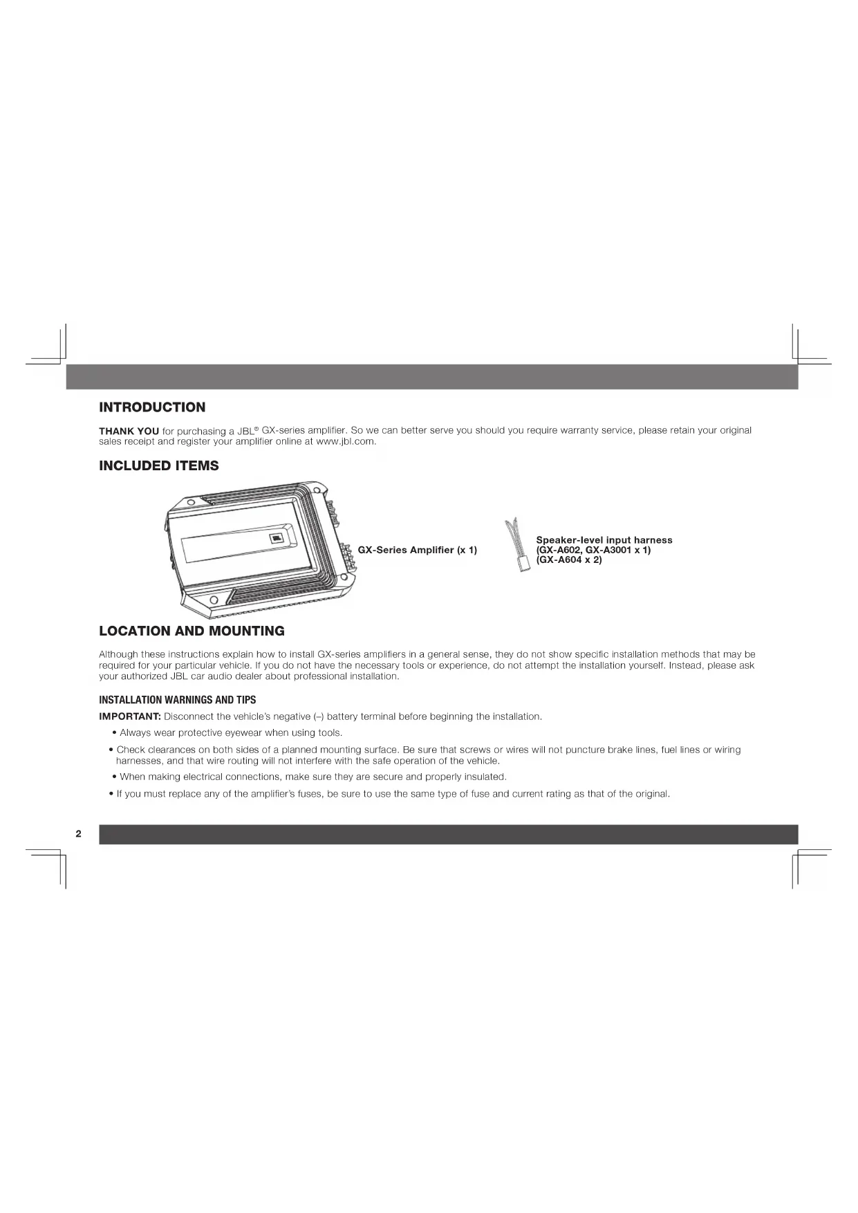
INCLUDED ITEMS
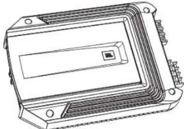
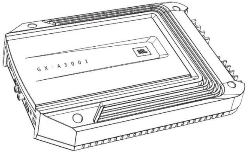
GX-Series Amplifier (x 1)
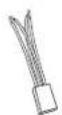
Speaker-level input harness (GX-A602, GX-A3001 x 1) (GX-A604 x 2)
LOCATION AND MOUNTING
Although these instructions explain how to install GX-series amplifiers in a general sense, they do not show specific installation methods that may be required for your particular vehicle. If you do not have the necessary tools or experience, do not attempt the installation yourself. Instead, please ask your authorized JBL car audio dealer about professional installation.
INSTALLATION WARNINGS AND TIPS
IMPORTANT: Disconnect the vehicle's negative (-) battery terminal before beginning the installation.
Always wear protective eyewear when using tools.
- Check clearances on both sides of a planned mounting surface. Be sure that screws or wires will not puncture brake lines, fuel lines or wiring harnesses, and that wire routing will not interfere with the safe operation of the vehicle.
- When making electrical connections, make sure they are secure and properly insulated.
If you must replace any of the amplifier's fuses, be sure to use the same type of fuse and current rating as that of the original.
INSTALLATION LOCATION
Amplifiers need air circulation to stay cool. Select a location that provides enough air for the amp to cool itself.
- Suitable locations are under a seat (provided the amplifier doesn't interfere with the seat adjustment mechanism), in the trunk, or in any other location that provides enough cooling air.
- Do not mount the amplifier with the heatsink facing downward, as this interferes with the amplifier's convection cooling.
- Mount the amplifier so that it will not be damaged by the feet of backseat passengers or shifting cargo in the trunk.
- Mount the amplifier so that it remains dry - never mount an amplifier outside the car or in the engine compartment.
MOUNTING THE AMPLIFIER
NOTE: You may find it more convenient to make all of the connections to the amplifier before you permanently mount it to the vehicle.
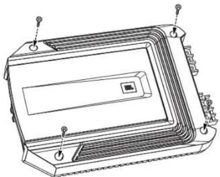
- Select a suitable mounting location as described above.
- Using the amplifier as a template, mark the locations of the mounting holes on the mounting surface.
- Drill pilot holes in the mounting surface.
- Attach the amplifier to the mounting surface with four appropriate mounting screws of your own choice. We suggest using #8 Phillips-head sheet metal screws. Make sure the amplifier is mounted securely.
www.jbl.com
POWER AND GROUND CONNECTIONS
IMPORTANT: Disconnect the vehicle's negative (-) battery terminal before beginning the installation.
The GX series amplifiers are capable of delivering high power levels, and require a heavy-duty and reliable connection to the vehicle's electrical system to achieve optimal performance. Please adhere to the following instructions carefully.
USING THE CONNECTORS
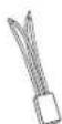
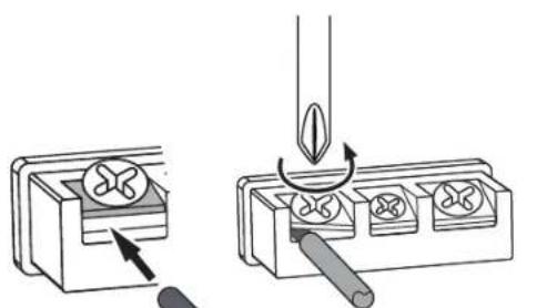
GX-series amplifiers use the same type of screw terminals for power and speaker connections. This type of terminal is easy to use and allows the easy connection of large-gauge wire.
To use the connectors, use a Phillips screwdriver to loosen the connector's set screw, insert the bare wire and tighten the set screw to secure the wire in the connector, as shown in the illustration below.
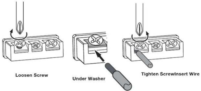
IMPORTANT: Make sure the (+) and (-) speaker bare wires do not touch each other or the other terminal at both the amplifier terminals and speaker terminals. Touching wires can cause a short circuit that can damage the amplifier.
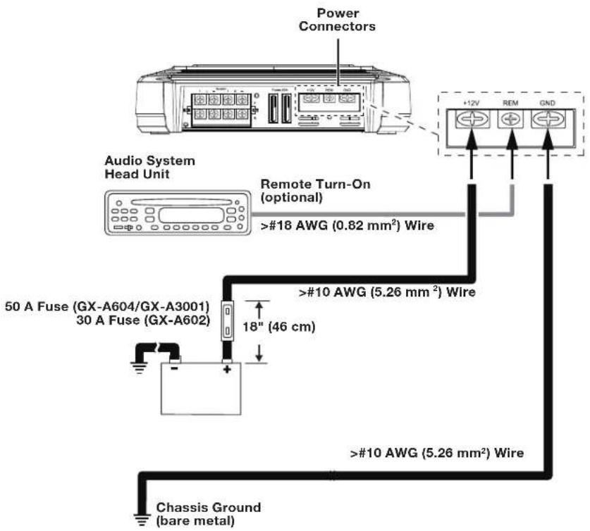
GROUND (GND) CONNECTION
Connect a wire (minimum 10 AWG - 5.3 mm²) from the amplifier's GND terminal directly to a solid point on the vehicle's chassis.
- For a good connection, use sandpaper to clear the paint from the metal surface at this chassis location. Use a star-type lock washer to secure the wire's connection.
POWER (12 V) CONNECTION
- Connect a wire (minimum 10 AWG - 5.3 mm²) directly to the battery's positive (+) terminal.
- Install a fuse holder for a 50 A fuse (GX-A604, GX-A3001) or a 30 A fuse (GX-A602) on this wire within 18^ (46 cm) of the battery's (+) terminal. Do not install the fuse in the holder at this time.
- Route this wire to the amplifier's location and connect it to the amplifier's +12 V terminal. Be sure to use appropriate grammets whenever routing wires through the firewall or other sheet metal. IMPORTANT: Failure to adequately protect the positive wire from potential damage may result in a vehicle fire.
- When you are finished routing and connecting this wire, install the appropriate fuse in the holder you installed near the battery.
(GX-A604, GX-A3001 - 50 A fuse;
GX-A602 - 30 A fuse)
SPEAKER AND INPUT CONNECTIONS
Always connect the (+) speaker terminal on the amplifier to the (+) terminal on the speaker and the (-) speaker terminal on the amplifier to the (-) terminal on the speaker.
IMPORTANT: Make sure the (+) and (-) bare wires do not touch each other or the other terminal at both the amplifier terminals and speaker terminals. Touching wires can cause a short circuit that can damage the amplifier.
GX-A604 SPEAKER CONNECTIONS: 4-CHANNEL OPERATION
Minimum speaker impedance: 2 ohms (each)
- Connect the front speakers to the FL and FR (+) and (-) terminals.
- Connect the rear speakers to the RL and RR (+) and (-) terminals.
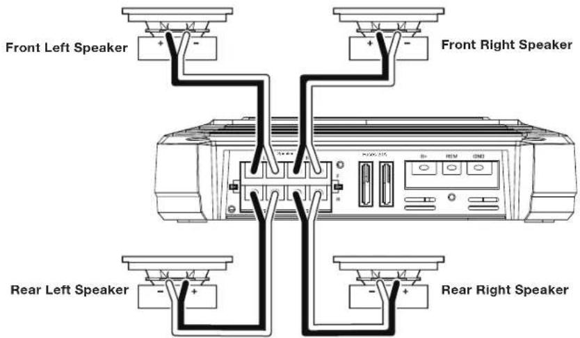
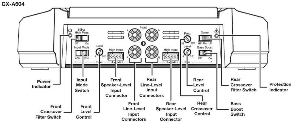
GX-A604 INPUT CONNECTIONS: 4-CHANNEL OPERATION
Connect your source unit or processor's front and rear left and right outputs to the amplifier's inputs as shown in the illustration.
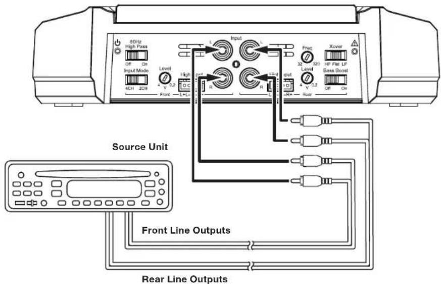
See Set The Crossover Controls, on page 20, for information about setting the amplifier's controls for 4-channel operation.
To use the speaker-level Inputs instead of the line-level Inputs, see Using The Speaker-Level Inputs, on page 12.
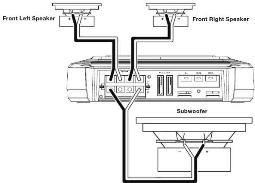
GX-A604 SPEAKER CONNECTIONS: 3-CHANNEL OPERATION
Minimum speaker impedance: 2 ohms each (left & right speakers); 4 ohms (subwoofer)
- Connect the left and right speakers to the FL and FR (+) and (-) terminals
- Connect the subwoofer to the RL (+) and RR (-) terminals. (The rear-channel Bass Boost control makes the rear channels preferable for subwoofer connection. See Set The Bass Boost, on page 23.) NOTE: You can connect two 2-ohm subwoofoers in series to maintain the required 4-ohm minimum impedance for the subwoofer channel.
GX-A604 INPUT CONNECTIONS: 3-CHANNEL OPERATION
Connect your source unit or processor's line outputs as shown in the illustration below. Set the input mode switch in the "4CH" position NOTE: Use a "Y"-adapter to connect the source unit's subwoofer output to the amplifier's rear left and right input jacks.
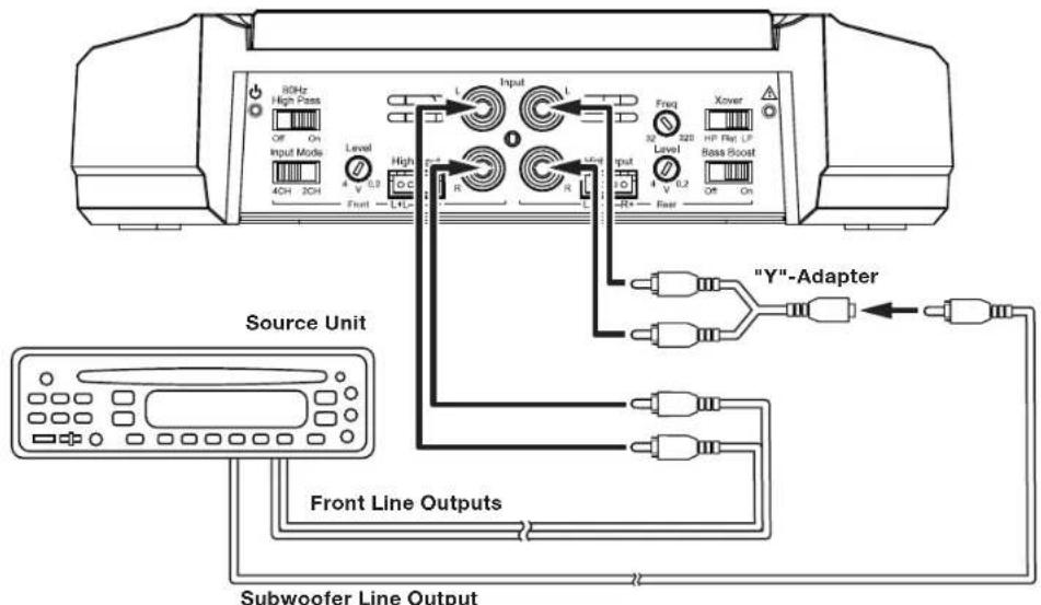
See Set The Crossover Controls, on page 20, for information about setting the amplifier's controls for 3-channel operation. To use the speaker-level inputs instead of the line-level inputs, see Using The Speaker-Level Inputs, on page 12.
www.jbl.com
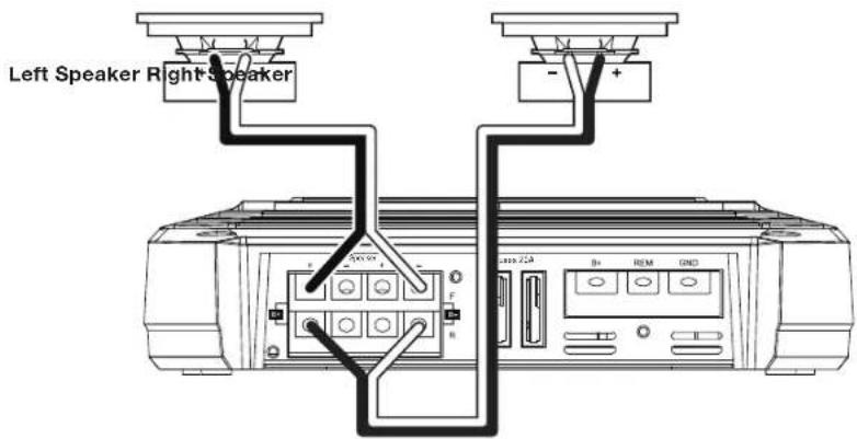
GX-A604 SPEAKER CONNECTIONS: 2-CHANNEL OPERATION
Minimum speaker impedance: 4 ohms (each)
Connect the left and right speakers as shown in the illustration below.
GX-A604 INPUT CONNECTIONS: 2-CHANNEL OPERATION
Connect your source unit or processor's line outputs as shown in the illustration below. Use only the front left and right input connections and make sure that the Input Mode switch is set in the "2CH" position.
See Set The Crossover Controls, on page 20, for information about setting the amplifier's controls for 2-channel operation.
To use the speaker-level inputs instead of the line-level inputs, see Using The Speaker-Level Inputs, on page 12.
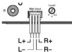
USING THE SPEAKER-LEVEL INPUTS
If your source unit doesn't have line-level outputs you can use the included speaker-level input harness to connect the amplifier to the source unit's speaker outputs. From left to right, the conductors are: L+, L-, R-, R+ (see the illustration to the right). The speaker-level connectors on all GX-series amp models follow this wiring configuration.
Follow the instructions in the previous sections, substituting the speaker-level connectors for the line-level connectors.
GX-A602 SPEAKER CONNECTIONS; 2-CHANNEL OPERATION
Minimum speaker impedance: 2 ohms (each)
Connect the left and right speakers to the FL and FR (+) and (-) terminals.
GX-A602 INPUT CONNECTIONS: 2-CHANNEL OPERATION
Connect your source unit or processor's line outputs as shown in the illustration below.
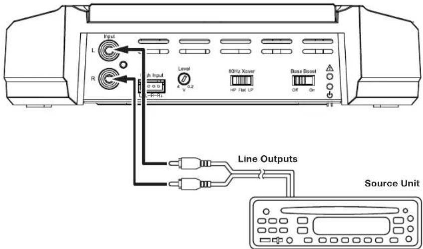
See Set The Crossover Controls, on page 20, for information about setting the amplifier's controls for 2-channel operation.
To use the speaker level inputs instead of the line-level inputs, see Using The Speaker-Level Inputs, on page 12.
GX-A602 SPEAKER CONNECTIONS: BRIDGED OPERATION
Bridged operation provides a single high-power channel for a subwoofer
Minimum speaker impedance: 4 ohms
Connect the subwoofer to the RL (+) and RR (-) terminals. NOTE: You can connect two 2-ohm subwooers in series to maintain the required 4-ohm impedance for bridged operation.
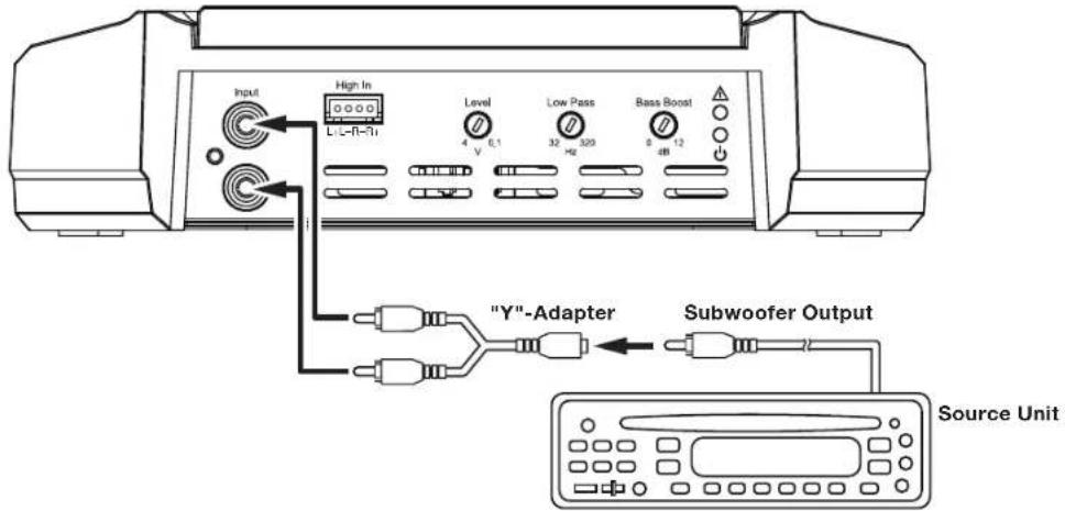
GX-A602 INPUT CONNECTIONS: BRIDGED OPERATION
Connect your source unit or processor's subwoofer line output to the amplifier's left input, as shown in the illustration below. NOTE: Use a "Y"-adapter to connect the source unit to the amplifier's left and right input jacks.
See Set The Crossover Controls, on page 20, for information about setting the amplifier's controls for bridged operation. To use the speaker-level inputs instead of the line-level inputs, see Using The Speaker-Level Inputs, on page 12.
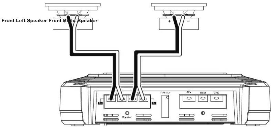
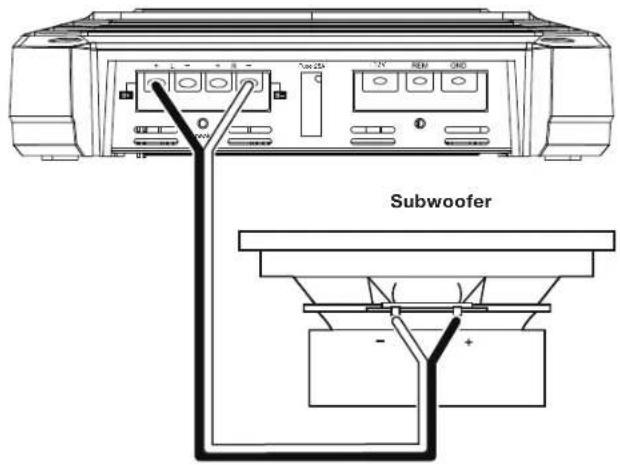
GX-A3001 SPEAKER CONNECTIONS
Minimum speaker impedance; 2 ohms (single subwoofer); 4 ohms (2 subwooers)
The GX-A3001 has two parallel sets of speaker connectors, allowing you to connect two subwoofoers.
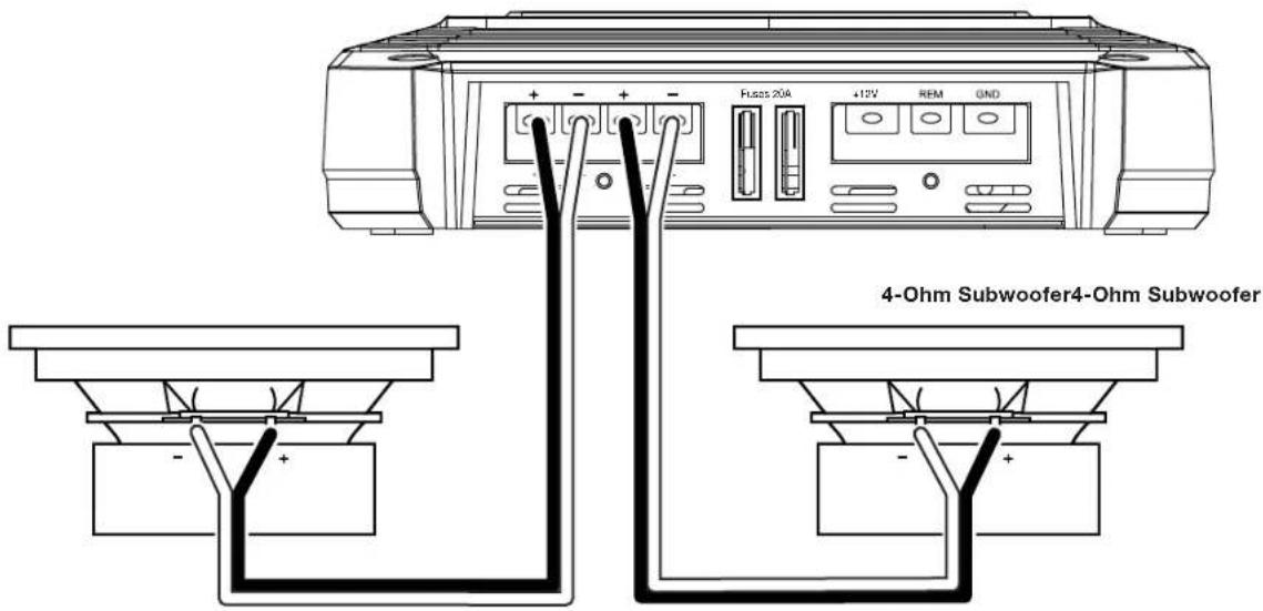
If you are using a single subwoofer you can connect it to either set of GX-A3001 speaker connectors.
- If you are using two 2-ohm subwoofoers you can connect them to one of the sets of connectors in series to be above the required 2-ohm minimum impedance.
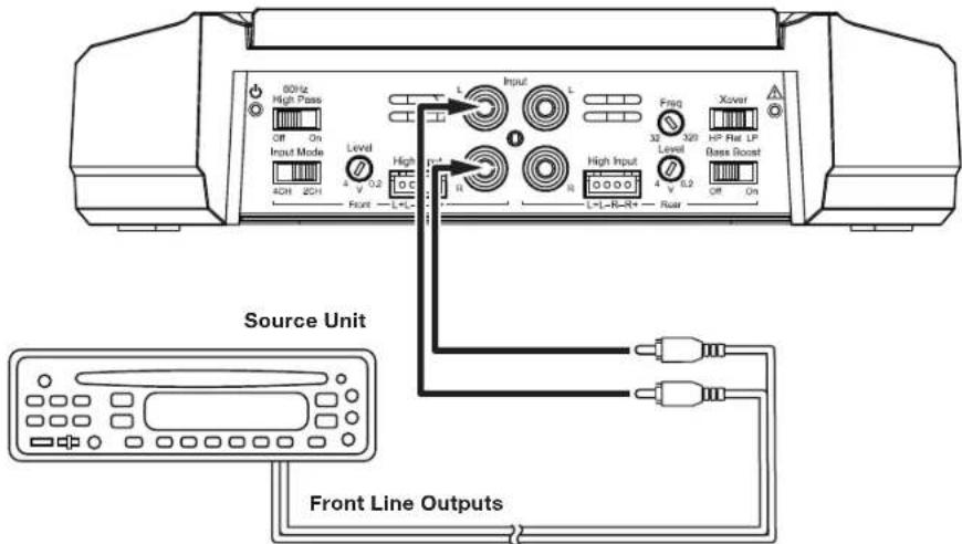
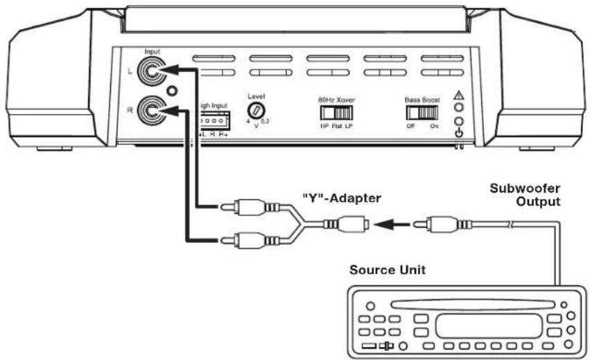
GX-A3001 INPUT CONNECTION
Use a "Y"-adapter to connect your source unit or processor's subwoofer line output to the amplifier's left and right inputs, as shown in the illustration below. If your source unit does not have a dedicated subwoofer output you can connect the rear left/right outputs to the amplifier's left and right inputs.
See Set The Crossover Controls, on page 20, for information about setting the amplifier's controls.
To use the speaker-level inputs instead of the line-level inputs, see Using The Speaker-Level Inputs, on page 12.
CONTROLS, INPUT CONNECTIONS AND INDICATORS
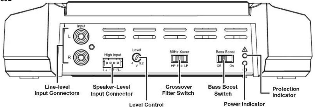
GX-A602
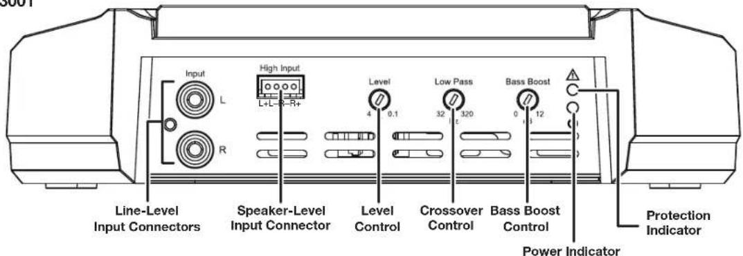
GX-A3001
www.jbl.com
SET THE CROSSOVER CONTROLS
Input Mode switch: Set the Input Mode switch in the "4CH" position.
Front Crossover Filter switch: Set the Front Crossover Filter switch in the "ON" (high-pass) position. This will limit the amount of low-frequency energy sent to the speakers, significantly reducing distortion and preventing the speakers from damage. Exception: If you have connected large full-range speakers (6" x 9" or larger) that can handle significant bass to the amplifier's front channels and you are not using a subwoofer in the system, set the Front Crossover Filter switch to the "OFF" (full-range) position.
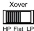
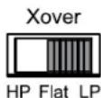
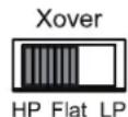
Rear Crossover Filter switch: Set the Rear Crossover Filter switch in the "HP" (high-pass) position. This will limit the amount of low-frequency energy sent to the speakers, significantly reducing distortion and preventing the speakers from damage. Exception: If you have connected large full-range speakers ( 6'' × 9'' or larger) that can handle significant bass to the amplifier's front channels and you are not using a subwoofer in the system, set the Rear Crossover Filter switch to the "FLAT" (full-range) position.
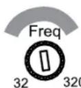
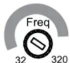
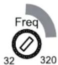
Rear Crossover control: When the Rear Crossover switch is set in the "HP" position, the Rear Crossover control determines the frequency where the low frequencies sent to the speakers begin to be reduced in volume.
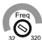
When running the amplifier in the 4-channel mode you should set the Rear Crossover control according to the size of the speakers connected to the amplifier channels - the smaller the speakers the higher you need to set the control to protect the speakers from damage. After initially setting the crossover frequency, listen to music with strong bass
that you are familiar with. If the speakers sound distorted or distressed, move the crossover frequency control to a higher setting to eliminate the distortion/ distress. The illustration to the right shows the recommended crossover filter frequency ranges for different speaker sizes.
6" and 5" Speakers 4" and Smaller Speakers


Input Mode switch: Set the Input Mode switch in the "4CH" position.
Front Crossover switch: Set the Front Crossover switch in the "ON" (high-pass) position. This will limit the amount of low-frequency energy sent to the speakers, significantly reducing distortion and preventing the speakers from damage.
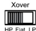
Rear Crossover Filter switch: When connecting a subwoofer or woofer to the rear channels, set the Rear Crossover Filter Switch in the "LP" (low-pass) position. This will limit the amount of high-frequency energy sent to the woofers or subwoofer, improving the clarity of vocals and other midrange sounds.
Low-Pass Operation: Subwoofer and Woofers
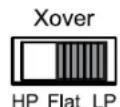
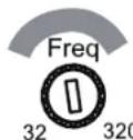
Rear Crossover control: The Rear Crossover control setting you use for subwoofer will depend on the type and location of your system's subwoofer. Start by setting the Rear Crossover control to a frequency somewhat lower than the 80 Hz setting on the front channels. After listening to music on the system for a time, fine-tune the Rear Crossover control setting to achieve a smooth transition from the subwoofer to the rest of the system's speakers while avoiding a "hole", where the sounds that occur between the subwoofer and other speakers seem to drop out. The illustration to the right shows the recommended Rear Crossover control frequency range.
Input Mode switch: Set the Input Mode switch in the "2CH" position.
Front Crossover Filter switch: Set the Front Crossover Filter switch in the "ON" (high-pass) position. This will limit the amount of low-frequency energy sent to the speakers, significantly reducing distortion and preventing the speakers from damage. Exception: If you have connected large full-range speakers ( 6'' x 9'' or larger) that can handle significant bass to the amplifier's front channels and you are not using a subwoofer in the system, set the Front Crossover Filter switch to the "OFF" (full-range) position.
Rear Crossover Filter switch: Set the Rear Crossover Filter switch in the "HP" (high-pass) position. This will limit the amount of low-frequency energy sent to the speakers, significantly reducing distortion and preventing the speakers from damage. Exception: If you have connected large full-range speakers ( 6'' × 9'' or larger) that can handle significant bass to the amplifier's front channels and you are not using a subwoofer in the system, set the Rear Crossover Filter switch to the "FLAT" (full-range) position.
Rear Crossover control: When the Rear Crossover switch is set in the "HP" position, the Rear Crossover control determines the frequency where the low frequencies sent to the speakers begin to be reduced in volume.
When running the amplifier in the 4-channel mode you should set the Rear Crossover control according to the size of the speakers connected to the amplifier channels - the smaller the speakers the higher you need to set the control to protect the speakers from damage. After initially setting the crossover frequency, listen to music with strong bass
that you are familiar with. If the speakers sound distorted or distressed, move the crossover frequency control to a higher setting to eliminate the distortion/ distress. The illustration to the right shows the recommended crossover filter frequency ranges for different speaker sizes.
6" and 5" Speakers

4" and Smaller Speakers

www.jbl.com
If you have connected the amplifier to a pair of 6" or smaller full-range speakers, set the Crossover Filter switch in the "HP" (high-pass) position. This will limit the amount of low-frequency energy sent to the speakers, significantly reducing distortion and preventing the speakers from damage.
- If you have connected the amplifier to a pair of large full-range speakers (6" x 9" or larger) that can handle significant bass and you are not using a subwoofer in the system, set the Crossover Filter switch to the "FLAT" (full-range) position.
If you have connected the amplifier to a pair of woofers or subwoofoers, set the Crossover Filter switch in the "LP" (low-pass) position. This will limit the amount of high-frequency energy sent to the woofers/subwoofoers, improving the clarity of vocals and other midrange sounds.
Crossover Filter switch: When operating the amplifier in bridged mode into a subwoofer, set the Crossover Filter switch in the "LP" (low-pass) position. This will limit the amount of high-frequency energy sent to the subwoofer.
GX-A3001
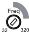
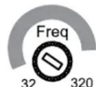
NOTE: The GX-A3001's internal crossover is permanently set for low-pass operation.
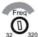
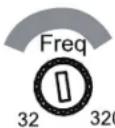
Crossover control: The crossover control limits the amount of high-frequency energy sent to the woofers or subwoofer. The crossover control setting you use for subwoofer will depend on the type and location of your system's subwoofer. Start by setting the crossover control to a frequency somewhat lower than the high-pass crossover setting you used for the system's other speakers. After listening to music on the system for a time, fine-tune the crossover control setting to achieve a smooth transition from the subwoofer to the rest of the system's speakers while avoiding a "hole", where the sounds that occur between the subwoofer and other speakers seem to drop out. The illustration to the right shows the recommended crossover control frequency range.
Subwoofer and Woofers
SET THE INPUT LEVEL
- Turn all the Level controls on all amplifiers fully counter-clockwise.
- Play some dynamic music through your source unit and turn its volume up to 3/4 volume.
- Slowly turn the Level control on the front-channel amplifier clockwise until the music begins to sound distorted.
- Turn the Level control counter-clockwise slightly until the music no longer sounds distorted.
- If you're using more than one amplifier or are using the GX-A604, repeat Steps 3 - 4 for all remaining amplifier Level controls.
SET THE BASS BOOST
GX-A604: When you're using the amplifier's rear channels to power a subwoofer, the Bass Boost switch can provide 12 dB of bass boost at 45Hz . (The switch only affects the amplifier's rear channels.) Set this switch according to your personal taste, but if using it causes audible distortion or bottoming of your subwoofer we recommend setting it to "OFF". CAUTION: Only use the Bass Boost switch if you've configured the rear channels to power a subwoofer. Using the Bass Boost switch with full-range speakers can damage the speakers.
GX-A602: When you're using the amplifier in bridged mode to power a subwoofer, the Bass Boost switch can provide 12 dB of bass boost at 45Hz . (Set this switch according to your personal taste, but if using it causes audible distortion or bottoming of your subwoofer we recommend setting it to "OFF". CAUTION: Only use the Bass Boost switch if you're using the amplifier to power a subwoofer. Using the Bass Boost switch with full-range speakers can damage the speakers.
GX-A3001: The Bass Boost control can provide up to 12 dB of bass boost at 45 Hz. Set this control according to your personal taste, but be careful not to set the control at a high enough level to cause audible distortion or bottoming of your subwoofer.
POWER AND PROTECTION LEDs
POWERLED
LED Illuminates orange: Normal operation (power is on).
LED is off: Amplifier is in standby mode.
PROTECTION LED
The amplifier's Protection LED should remain off during normal operation. If there is no sound from the amplifier and the Protection LED illuminates red, see Troubleshooting, on page 24.
TROUBLESHOOTING
If your amplifier isn't performing the way you think is should, check to see if the problem is covered in this section before calling your dealer or contacting JBL customer service.
PROBLEM CAUSES AND SOLUTIONS
| No sound (the amplifier's Power LED is off) | - Check that the amplifier's +12 V and GND connections have been properly made. - Check if the fuse on the +12 V wire located near the battery is blown: If so, replace it with an identical fuse. - Check all amplifier fuses; if any are blown, replace them with identical fuses. - If you are using the amplifier's REM connection for turn-on, check that the wire is properly connected to the audio system's remote turn-on wire or to the vehicle's ACC power terminal. |
| No sound (the amplifier's Power LED is orange) | - Check that all amplifier input and speaker connections have been properly made. - Check that the amplifier's Level controls are not turned all the way down (counter-clockwise). - Check that the vehicle audio system's source unit's volume control is not turned all the way down. |
| No sound (the amplifier's Protection LED is red) | - Confirm that the vehicle's electrical system is supplying between \( 9\mathrm{\;V} \) and \( {16}\mathrm{\;V}\mathrm{{DC}} \) to the amplifier. If the supply voltage is outside of this range, correct the condition before attempting to use the amplifier. - If the amplifier has overheated, wait until it has cooled down before attempting to use it again. - Disconnect all speakers from the amplifier and attempt to turn it on again: - If the amplifier turns on (the Power LED is orange), there is a short circuit in one or more of the speaker wires. Correct all short circuits before reconnecting the speakers to the amplifier. - If the amplifier does not turn on (the Protection LED is still red and the Power LED is off), contact your authorized JBL dealer for assistance. |
PROBLEM CAUSES AND SOLUTIONS
| Sound only comes from some of the speakers connected to the amplifier | - Check that the vehicle audio system's source unit's balance and fader controls are set to their center (midpoint) positions. - (GX-A604): Check that the setting of the amplifier's Mode Switch matches the input and speaker connections made to the amplifier |
| Sound is too quiet, even with the vehicle audio system's source unit volume all the way up | - Check that the amplifier's Level controls are not turned too low. See Set The Input Level, on page 22, for information about setting the Level controls. |
| Sound in the front/rear speakers is distorted | - Make sure the amplifier's Crossover Filter switch for the distorted channels is set to HP. - Set the Crossover control for the distorted channels to a higher setting. - Check that the distortion is not originating from the vehicle audio system's source unit. |
| Sound in the subwoofer is distorted | - (GX-A604, GX-A602): Set the Bass Boost switch to "OFF". - (GX-A3001): While listening to bass-heavy music, turn the Bass Boost control all the way down, and then gradually increase it until the distortion begins to return. Reduce the Bass Boost control setting slightly to eliminate the distortion and leave it set there. - Check that the distortion is not originating from the vehicle audio system's source unit. |
SPECIFICATIONS
| GX-A604 GX-A602 GX-A3001 | |||
| Max power (15.5 V, 1 kHz, 10% THD, total ch, 2 ohms) | 435 W | 280 W | 415W (15.5 V, 50 Hz, 10% THD, 2 ohms) |
| Rated power output @ 4 ohms 60 W x 4 | 60 W x 2 | 200 W x 1 | |
| Bridged power output (4 ohms, 1% THD) | 170 W x 2 | 170 W x 1 N/A | |
| THD+N at rated power <1% <1% <1% | |||
| Signal-to-noise (2 V @ 4 ohms) >75 dB >75 dB >75 dB | |||
| Effective damping factor (4 ohms) >50 >50 | |||
| Frequency response (-3 dB) 20 Hz - 20 kHz ±1 dB 20 Hz - 20 kHz ±1 dB 10 Hz - 320 Hz | |||
| Maximum input voltage | 20 V | 20 V | 20 V |
| Maximum input sensitivity | 200 mV | 200 mV | 200 mV |
| Fuse size | 20 A x 2 | 25 A 20 A x 2 | |
| Dimensions (H x W x D) | 2-1/16" x 11-13/16" x 8-1/8" (52 mm x 300 mm x 206 mm) | 2-1/16" x 7-13/16" x 8-1/8" (52 mm x 198 mm x 206 mm) | 2-1/16" x 11-7/16" x 8-1/8" (52 mm x 291 mm x 206 mm) |
| Weight | 5.3 lb (2.4 kg) | 3.8 lb (1.7 kg) | 5.3 lb (2.4 kg) |
GX-A604/GX-A602/GX-A3001
Veränderer
CONNEXIONS DES ENTRES AU GX-A602: FONCTIONNEMENT AVEC PONT
GX-A602:FONCTIONNEMENT AVEC 2 CANAUX
PROBLEM CAUSES ET SOLUTIONS
PROBLEM CAUSES ET SOLUTIONS
Amplificatore series GX (x 1)
6-Ⅲ5-IOHMOBbIe DnHaMKN

4-IOMOBbie DnHaMnKm MeHbWe

PnncnoB3oBAHN ycnntBn B 4-KaHbHOM peKHeM cneJeYcTaHaBnBaTb peryIaTO pAcToBt KpocOBepa 3aHnx KaHNoB B COoTBcTBTn Cpa3Mepom DnHAMKOB, NOKIOHaeMbIX KycNITeIO: Yem MeHbIe DNAMKK, TEm BBIe DOJNKHa 6blb noporobaa cactota KpocOBepa. Iocne nepBOHaAHbONyAChToB KpocOBePA nocnyaIte N3bcETHyIO Bam My3bIKy C hacbiEHHBMn Bacamn. Ecn nnHAMKn Nckkaiaot 3ByuHMe, noBcIbe NoporOByu cactOy KpocOBePA, Yo5bIaBnTcBcT O 3TOrO NCKaKeHn. Ha IIIOCTpaunn cnPaba NOKa3AH npIMepHbn dnaanaoh cactOT kpcocObepa dnn DnHAMKOB pa3HOrO pa3Mepa
GX-A604:3-KAHAHBHA CNTEMA
IpeeknouateBbXoHoro pexima: YcTaHOBtne nepeknOaTeB bXoHoro peKmBa noJooKeHne "4CH".
IpeeknouateIb pexima boaobtI kpoocobepa nepeidnx kaanob: YctahOBITE nepekniOyateIb kpoocobepa nepeidnx kaanob B noNooKHe "ON" (nponyckAOTc cactotbl bIwe nporogob Iactotbl). 30rOpaHHT MOUHCTb HsKoACToTHbX CnHApOB, NOCTyaHIOxB DnHAMKn, 303HaNTeJbHO CHNkaet NCKAKeHHe INpeOxoPAHReT DnHAMKn OT nobpeKDeHn.
Pponyck Hn3KoactOThbIX CNrHaNoB:ca6Byepebl N Byeepbl

Ipeeknouateb pexima paobtki kpoccobepa 3aHnx KahanOB: Pnp noKnIOueHm cabByepe Hnn Byepe K 3aHmKahanam yctahOBITE peeknouateb kpoccobepa 3aHnx KahanOB B noNOeHne "LP" (nponyckAOTc aactotbl Hnke nporobou qactotbl). 3TO ORPAHHT MOUHOCTB BicOKOCAOTbIX CnHANOB, NOCTyNAIOUIX B cABbyepe Hnn Byepe, OT Yero BOKAN CTAHET 0oJe eYKIM N 6yDy T MehJWe NCKAATBC3yKN CpeHrE OACTOTHO Dnana3OHa.
PerynTOp noporoBoH qactoBtI KpoccoBepa 3adnHex KaHANOB: HAcTpoNkpepyrJrTopa cactoBtI KpoccoBepa 3adnHex KaHANOB 3abNCIT OT TnA IN PacnoNojEHNb Bawaero ca6bypepa. HauHNTe C nporoBOH qactoBtI KpoccoBepa YtB NHe 80 T, IpocnyuAB My3ky, NoDperyInpyte nporOBOHy OACTOTy KpoccoBepa 3adnHex KaHANOB TAK, YTObI pOncXoDIN nnAbHbN nepeXod OT ca6bypepa K octanbHIMn DnHaMnKam CnCTEmbl 6e3 "npoBaIA", KOrda BInadaet 3yK MekNy ca6bypepm O octanbHbIMn DnHAMNKAMn. Ha nllIOCTpaun Cnpaba NOKa3aHO npimepHoe nnonKeHne peYrJrTopa qactoTb KpoccoBepa 3adnHex KaHANOB.
GX-A604:2-KAHANbHAR CNTEMA
IpeeknouateBbXoHoro peKIMa:YcTaHOBtnepeeknouateBbXoHoro peKIMa B noLoKeHne "2CH".
Peknouatenb pexma pa60tbl KpoccoBepa nepeHnx kaHAnOB: YctahOBITE pekeKIOUATEb KpocCOBepa nepeHnx kaHAnOB b noNOxHe NONHINN HANOB, NOCTyAHOuX B DnHaMMK, 3NoTbno HcHKeAET npeOxApoHae TnHAMMK ONBpeHne: Ecmbl NockIOUHN BOnBue noNoHmna3oHbIe dHAMHK (15 x 22 cm mnn 60bnse), KToptbe Moryt cnpabTbc o6pa60koub BpeHnx KaHAnAe u bHe Ucnb3ye me ca6byep e CucMeMe, yctahOBite nepeKIOUATenb KpocCOBepa nepeHnx kaHAnOB b noNOxHe "OFF" (nocTyaNt tonhnn CInHan).
IpeKluOATEnbpeKIMpa6oTbI KpoccoBepa 3adHnx KaHAnOB: YCTAHONepeKluOATEnb KpocCOBepa 3aHnIX KaHAnOB bNOJIOKeHne "HP" (nponycakatoTc aactoTb Biwe noporobov cactoTb).3To ORpAHHNT MOUHOCTb HN3KOaCTOHbX CINHAOB, NOCTynAHOHNb X DnHAMKK, YTO 3HaUHTeBbHO CHNJaET NCKaKeHne H npedeoxpaHReT dHAMNKt ON NOBpeKdHnR. MckNoHee: Ecn Bbl NOJIOHnn 60bnbEe NOHNODnA3OONbHe DnHAMNK (15 x 22 cm nnnn 60bnSe), KOtOpBle MOrY cnpabTbcC ocbapOtKb BacOB b NepeDnHex KAHANAX U ebl He uCnOB3yeme cabByep e CucmeMe, yctahOBInTe peKluOATEnb KpocCOBepa 3aHnIX KaHAnOB b NoJIOKeHne "FLAT" (noCTynaet noHNb ciHnA).
6-Ⅲ5-IOHMOBbie DnHaMnKu
4-IOHMOBbieINHAMKIN MeHbIe

PeynTop nporob noctb kpcocbepa 3aHnx KaHNOE CnnepeKIOHTeB KpocOBePA 3aHNX KAHNOB yCTAHOBEN B NOJOKHNE "HP", c nmoTIO peryIopTa qactoBk PocOBePA 3aHNX KAHNO MxOHOy UCACTOTy, HNKe KOtPOB cyueCTBeHH OmyehsAETO MoUHOCT CNHANOB, NOCTYNAUONX B DINAHAMNK.
PnncnoB0aHnn yCInnten B 4-kaHbHom pexime Cneyet yctanabnbatb pernytop qactotb kpcocobepa 3aHnx kaHNOB COOTBeCTBn Cpa3MePOM DnHAMKOB, NOKIOVAeMbX Kcynntteo: Yem MeHbIe DnHAMNK, TEm Bblwe dONKHa 6bbl noporOBAA cactota kpcocobepa. Nocne nepBOHauNBoHOn yCTaHOBKn Cactotb KpocOBa PocnyaTe HBeCTHyO Bam My3bky C hAcblEHNbIMN bacAM. EcnDnHAMNK INCKAJO T 3ByAHHe, NOBcBte NopOROBy AactOT KpocOBepa, TOb6136aBnTc8r OTO rOKKaKeHHa. Ha nIOCTpaun CNpBa NOKa3AH npimepHbn Dnanaoh CactOT KpocOBepa dna DnHAMKOB pa3HOro pa3Mepa.
www.jbl.com
GX-A602:2-KAHANbHAR CNTEMA
IpeeknoateIb pejma pa6OtbI KpoccoBepa KaHaNoB:
-ECnBbI NOckNIOHIN K YcINNTENNO npay 6-IOHMOBxIN NOHOANANA0HNBHXIN HAMMKOB (15 CM) ININ DnHAMNK EeHE MeHbEPO pa3Mepa, yCTaHOBIte NpeKIOUATEb KpOCCOBa KAHOAN B NOJIOEHE "HP". OTo ORPAHHT MOOHOCb MHKOAcTOTHbCnHBO, NOCTyNAIOUIX B DAHAMNK, YTO 3HAHTNE CnHxAET NCKAEGHE IN PpeDOxPAHET NDAHMMK OT NOBPEKDEHN.
EcnBbnoNnnpnyKpyhHbixnoHNOHnana3oHHbIXdHaMnKOB(15x22cmnn60nbwe),KOTOpBE MoryT cnpaBnTcO6pa6tKoBACOB B nepeHnX KaHnax u bHe uCnOy3ye me ca6byep e cucmeMe, yctahOBnTe nepeKIOuATEb KpocCOBepa B noIooKeHne "FLAT" (noCTynae TnoHbn CmHn).
- Ecnn Bbl nocknnoyn K ycnntennp npay cabbypeop nnn Bypeop, ytaohnne nepeknouatene kpcocobepa b noonxehe "LP" (nponycakotca qactotb Hnke npoobor hactotb). 30 Orpargnnt moochtb Bicokocactothxir CmharnoB, noctynaowin B cacbype npy Byep, ot hrro BOKan CTahET bcNn M bydUT mHebe NCKAKtcbcBkycpeHrOACTOTHO Dnana3OHa.
GX-A602:MOCTOBAR CXEMA
Pepeknouatebpekma paobtki kpcocbepa: Pn nooknoeHm ca6byepa K yucntenno no moctoBcme yctahOBte nepeknovatelb kpcocbeba nnonoxene "LP" (nponyckacotcaactohtb Hnke noporoBqacto).3To orpahnHT moohCTb BBCOKOACTOThbx CnHaoB, noctyauuixb c6byepf.
GX-A3001
PIMMEUAHNE. BHytpenHnn KpoccoBep ycHnTeTg GX-A3001 nocToHHo yctaHOBJeHa pa6OyB pexKme npOnycka Hn3KooaCToTHbIX CnHnAOB (LP).
PerynTop nporoboh qactotbI kpcocbepa C nmoBIO peryrnapo cactObl KpoccoBepa orpAHNBAeTc MOHOCb BbCOKoyactOthx CnHAnOB, noctyaonuBn Cabbyep. Hacptnoka perylnpa nporoBop aactObl kpcocbepa 3aBNCIT OT TnI n pacnojoxehna Baaero caabypepa. Hauhnte C qactObl ytBu NHexe nporoBop qactObl, yctahOBHeHO BAMn DnApynx DnHAMNKOB Bawei cnCTembl. Ipocnyab MBykky, noDperynupyte nporoBOpY OuaCTObl KpoccoBepa TaK, YTO6bl npocXOJI INAIBHn nepeXOD OT cabbyepa K octanbHbIMn DnHAMNKAM CNCTEMbl 6e3 "npOBaIa", KOrda BInIaTaET 3BYK MExdy cabbyepom n octalbHbIMn DnHAMNKAMn. Ha nllIOCTpaunn cnPaba noka3Ho npimephoe nnonKeHne peryrnapo qactOTb I kpcocbepa.
Ca6BypepbI n BypepbI
YIPABJEHNE YCNJIEHNEM CNGHAIOB
1.Повернite BcepernyatopbyucinHnCINHANOBHaBCEXyHInTeTnI npOTNBacOBoN CTpeKnDoynopa.
2. BknoHHTe IIO6yO DNHAMnueckyo M3bky B nCTOuHnke ayDnOCnHAnOB uYcTaHOBtpepyrTOp rpOMKoCTn Ha 3/4 OT mAKCMaJIbHOI rpOMKoCTN.
3. MeDneHNO nobopauBaIte pernyTOp yCnHEnn CnHAnOB nepeDnHex KAnAOB no YacBOB CTpeKe, noka BocnpOn3BeDeHne My3bIK He HaHTNckKaTaBcA.
4. NOBEPHNE HEMHO rpeyIaTOp ycHHeHrCnHAnOB nepdHnx KaHAnOB npOTNB cTpeKN, NOKA BOCNPOH3BeDeHne My3bIK He nepeCTaHET NCKAKaTBcR.
5. Ecnn Bn IcnoIb3yIte HeckoIbko yCunIteNe nn moen GX-A604, noBtOpIte warn 3 - 4 nBaCEX octaIbHbIX perpyIantopOB ycInneHn CnHaIOB.
YCJIJIeHHe BACOB
GX-A604: EcnBb noKIOUcBcBpycp K 3aHMM KaHAM ycNITeR, MOXHO BKNIOHTy cYNHHe 6acOB, oecneuB rpoMocb Ha ypOBe 12 dIraacToB 45 Tc. (PhHKua yCINENHbaoc BoB TONbKO HA 3aHNe KaHANbY CynNTeR.) Ecn yCINHHe 6acOB B3bBaet 3aMeTHoe nckAekHe 3bka INc CaBcyep "3axNEbBAeTc", Mbl peKOMeHNyEM BkKnIOHTy cYNHHe 6acOB, nepeBeda nepeKIOHTeJIy cYNHHe 6acOB bnoJooHHe "OFF." NPEUYPEXDEHNE: BknOauTe YcNtHHe 6acOB TOnbKO b Tom cNyae, ecn K 3aHMM KaHAM yCINNTeR noKDIOHue HcBcyep. Ecn noKIOUcTB nonHOdna3oONHbIe DNHAMNK K 3aHMM KAHAM m BKNIOHTy ycNtHHe 6acOB, to 3Tu DNHAMNK MOryt nobpeinbcra.
GX-A602: Ecnn Bbl noKIOHnIcBbpyep ycHNTeIO NO MocTOB O CXeME, MoXHO BKNIOHTb ycHHe 6acOB, oecneueINr pOMKocTb Ha ypOBHe 12dIy auctoTI 45 Tc. Ecnn ycHnHHe 6acOB B3bIbAeT 3aMeTHOE nCKAKeHHe 38yKa IINc cABsypeP "3axNEbBAeTcM, My peKomeHdyem BkIOuHTb ycHHe 6acOB, nepeBnEpeKIOvateNb ycHHe 6acOB B noNOxHe "OFF." PEPDyPPEJHE: BkIOuATEy ycHHe 6acOB TObKO B TOM CNYae, eCNI K ycHnHToNo noKIOHHe 6abBypeP. Ecnn noKIOHNTb K ycHNTeIO noNHOHaNA3OHHBe IINAMIK IN BkIOUHTb ycHHe 6acOB, To 3TN DnHAMNK MOrYT nobpeNTbcR.
GX-A3001: C nOmoiho perynIaTOpA ycInHeHb 6acOB MOxHO yCInHb 6abI do ypoBHa 12 d5 ha qactote 45 Fu. PerynHyTe ycInHeHb 6acOB no CBOy My BcCy, Ho He nepeycepcDCTByIte: Upe3MepHoe ycInHeHne 6acOB MoKET npINBeCTN K 3aMeTHOMy NcKaKeHIO 3bYka MII "3axNe6bIbAHIO" c6Baoyepa.
CBETOIOIDHbIE INIINKATOPbI
INHДNKATOPПNTAHNIA
- INHINKATop CBeITcra opAHKeBbIM CBETOM: HopMaIbHa paBoTa (NHTaHHe BKNIOUeHo).
- INHdkaTop He ropnt: ycunnteIb HaxoundTcB peKmme OxuHaHn.
3AUHTbI INHINKATOP
3aunTHbHnHnKATOp He dOnJxH eopB B xOe HopMaHbHO pa60tBJ. Ecn yCnInTeB 3amOnHAn, a 3aunTHbHnHnKATOp 3arOpenc KpaChbIM CBETOM, To 3o CBNDeTebCTByE To HncnPabHocTN - CM. pa3en Nouck u ycmpaHeue HeucnpaHocMeu Ha ctp. 24.
NONCK N YCTPAHEHNE HENCIPABHOCTEIN
Ecnn BaM kaxketca, yTo ycHnnteB pa60taet HecnpabHo, npOBepbTe, ecTb nn OnncanHe Baaew np6nembl B daHHom pa3dene, nepeTEm, KaK 3BOHHT bDnepy JBL nnn CByaTbcra co cykbo NOpdePckkn KIneHToB JBL.
PNOBJIEMA PPNUHbI NPEWENH
GxSRIZnEeNnTnIeMfHsFJFJFJFJFJFJFJFJFJFJFJFJFJFJFJFJFJFJFJFJFJFJFJFJFJFJFJFJFJFJFJFJFJFJFJFJFJFJFJFJFJFJFJFJFJFJFJFJFJFJF
封的子,如用,其

: (+) 且(-)S形F首,T自,T自,T自,T自,T自,T自,T自,T自,T自,T自,T自,T自,T自,T自,T自,T自,T自,T自,T自,T自,T自,T自,T自,T自,T自,T自,T自,T自,T自,T自,T自,T自,T自,T自
GND(臨時)臨時
:(+)[(-)n]i1i1i1i1i1i1i1i1i1i1i1i1i1i1i1i1i1i1i1i1i1i1i1i1i1i1i1i1i1i1i1i1i1i1i1i1i1i1i1i1i1i1i1i1i1i1i
GX-A604S形封函简历:4删网
SπFurHcHsJHfTnS:2ohm(
PLAATS VAN INSTALLATIE
GX-A604: 4-KANAALS FUNCTIE
GX-A602: 2-KANAALS FUNCTIE
Crossover-filterschakelaar:
VOEDING EN BESCHERMING LED'S
VOEDING-LED
GX-A604 HÖGTALARANSLUTNINGAR: 4-KANALSDRIFT
GX-A604 HÖGTALARANSLUTNINGAR: 2-KANALSDRIFT
Minsta hegtalarimpedans: 4 ohm (vardera)
ANVANDA HÖGTALARNIVÄINGÄNGARNA
GX-A602 HÖGTALARANSLUTNING; 2-KANALSDRIFT
Minsta hegtalarimpedans: 2 ohm (vardera)
GX-A3001 HÖGTALARANSLUTNINGAR
Minsta hegtalarimpedans; 2 ohm (en subwoofer); 4 ohm (tvá subwooers)
LED FÖR STROM OCH SKYDD
STRÖM-LED
LED lyser orange: Normal drift (strömmen pa).
LED lyser inte: Forstarkaren i standbylage.
SKYDDS-LED
(GX-A602, GX-A3001 x 1)
(GX - A604× 2)
SIJOITUS JA ASENNUS
| Ses sadece amplifikatore®,®,®,®,®,®,®,®,®,®,®,®,®,®,®,®,®,®,®,®,®,®,®,®,®,®,®,®,®,®,®,®,®,®,®,®,®,®,®,®,®,®,®,®,®,®,®,®,®,®,®,®,®,®,®,®,®,®,®,®,®,®,®,®,®,®,®,®,®,®,®,®,®,®,®,®,®,®,®,®,®,®,®,®,®,®,®,®,®,®,®,®,®,®,®,®,®,®,®,®,®, bazine, benzyl, benzyl, benzyl, benzyl, benzyl, benzyl, benzyl, benzyl, benzyl, benzyl, benzyl, benzyl, benzyl, benzyl, benzyl, benzyl, benzyl, benzyl, benzyl, benzyl, benzyl, benzyl, benzyl, benzyl, benzyl, benzyl, benzyl, benzyl, benzyl, benzyl, benzyl, benzyl, benzyl, benzyl bazine, benzyl, benzyl, benzyl, benzyl, benzyl, benzyl, benzyl, benzyl, benzyl, benzyl, benzyl, benzyl, benzyl, benzyl, benzyl, benzyl, benzyl, benzyl, benzyl, benzyl, benzyl, benzyl, benzyl, benzyl, benzyl, benzyl, benzyl, benzyl, benzyl, benzyl, benzyl, benzyl, bizi, benzyl, benzyl, benzyl, benzyl, benzyl, benzyl, benzyl, benzyl, benzyl, benzyl, benzyl, benzyl, benzyl, benzyl, benzyl, benzyl, benzyl, benzyl, benzyl, benzyl, benzyl, benzyl, benzyl, benzyl, benzyl, benzyl, benzyl, benzyl, benzyl, benzyl, benzyl, benzyl, benzyl, bizi, benzyl, benzyl, benzyl, benzyl, benzyl, benzyl, benzyl, benzyl, benzyl, benzyl, benzyl, benzyl, benzyl, benzyl, benzyl, benzyl, benzyl, benzyl, benzyl, benzyl, benzyl, benzyl, benzyl, benzyl, benzyl, benzyl, benzyl, benzyl, benzyl, benzyl, benzyl, benzyl, benzYL, bizi, benzyl, benzyl, benzyl, benzyl, benzyl, benzyl, benzyl, benzyl, benzyl, benzyl, benzyl, benzyl, benzyl, benzyl, benzyl, benzyl, benzyl, benzyl, benzyl, benzyl, benzyl, benzyl, benzyl, benzyl, benzyl, benzyl, benzyl, benzyl, benzyl, benzyl, benzyl, benzyl, bizi, bizi, bizi, bizi, bizi, bizi, bizi, bizi, bizi, bizi, bizi, bizi, bizi, bizi, bizi, bizi, bizi, bizi, bizi, bizi, bizi, bizi, bizi, bizi, bizi, bizi, bizi, bizi, bizi, bizi, bizi, bizi, bizi, bizi bizi, bizi, bizi, bizi, bizi, bizi, bizi, bizi, bizi, bizi, bizi, bizi, bizi, bizi, bizi, bizi, bizi, bizi, bizi, bizi, bizi, bizi, bizi, bizi, bizi, bizi, bizi, bizi, bizi, bizi, bizi, bizi, bizi, . bizi, bizi, bizi, bizi, bizi, bizi, bizi, bizi, bizi, bizi, bizi, bizi, bizi, bizi, bizi, bizi, bizi, bizi, bizi, bizi, bizi, bizi, bizi, bizi, bizi, bizi, bizi, bizi, bizi, bizi, bizi, bizi, bizi, Bizi, bizi, bizi, bizi, bizi, bizi, bizi, bizi, bizi, bizi, bizi, bizi, bizi, bizi, bizi, bizi, bizi, bizi, bizi, bizi, bizi, bizi, bizi, bizi, bizi, bizi, bizi, bizi, bizi, bizi, bizi, bizi, bizi, bitti bitti bitti bitti bitti bitti bitti bitti bitti bitti bitti bitti bitti bitti bitti bitti bitti bitti bitti bitti bitti bitti bitti bitti bitti bitti bitti bitti bitti bitti bitti bitti bitti bitti Bitti bitti bitti bitti bitti bitti bitti bitti bitti bitti bitti bitti bitti bitti bitti bitti bitti bitti bitti bitti bitti bitti bitti bitti bitti bitti bitti bitti bitti bitti bitti bitti bitti bitt bitti bitti bitti bitti bitti bitti bitti bitti bitti bitti bitti bitti bitti bitti bitti bitti bitti bitti bitti bitti bitti bitti bitti bitti bitti bitti bitti bitti bitti bitti bitti bitti bitti |
TEKNIK OZELLIKLER
(GX-A602, GX-A3001 x 1)
(GX-A604 x 2)
LOKASI DAN PEMASANGAN
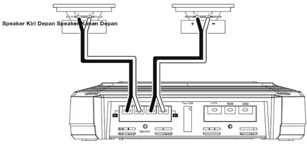
KONEKSISPEAKERGX-A602;OPERASI2-CHANNEL
Impedansi speaker minimal: 2 ohm (masing-masing)
Hubungkan speaker kiri dan kanan ke terminal (+) dan (-) FL dan FR.

KONEKSI INPUT GX-A602: OPERASI 2-CHANNEL
HARMAN International Industries, Incorporated 6500 Balboa Boulevard, Northridge, CA 91329 USA
© 2013 HARMAN International Industries, Incorporated. All rights reserved.
JBL is a trademark of HARMAN International Industries, Incorporated, registered in the United States and/or other countries.
All Rights Reserved. Features, specifications and appearance are subject to change without notice.
Part No. 20130624 Rev: A
www.jbl.com