
GETUP - Range hood ELICA - Free user manual and instructions
Find the device manual for free GETUP ELICA in PDF.




| Product type | Range hood |
| Brand | ELICA |
| Model | GETUP |
| Use version | Extractor (external) or recirculating (internal recycling) |
| Connection diameter | 150 mm |
| Maximum duct length | 5 meters |
| Maximum total power (gas hob) | Up to 13.7 kW depending on configuration |
| Electrical supply | See rating plate (typically 220-240 V, 50/60 Hz) |
| Safety class | Compliant with EN/IEC 60335-1 and -2-31 |
| Connectivity | WiFi 2.4 GHz via Elica Connect app |
| Controls | Touch panel with open/close functions, lighting, WiFi, extraction speeds, Boost |
| Extraction speeds | 3 speeds + Boost 1 (30 min) and Boost 2 (7 min) |
| Lighting | LED with dimming |
| Grease filter | Metal, dishwasher safe (gentle cycle) or hand wash |
| Charcoal filter (optional) | Washable, replace every 3 years or if damaged |
| Filter saturation indicator | Flashing L1 lights: grease (simultaneous) / charcoal (alternating) |
| Recommended maintenance | Clean exterior and interior at least once a month |
| Minimum distance from hob | 400 mm (components above); 650 mm for electronic unit |
| Child safety | Use by children aged at least 8 years under supervision |
| Repairability | Spare parts available from authorized Elica service |
| Warranty | Valid subject to proper installation and use |
| Countries where Elica Connect is available | List available at www.elica.com |
Frequently Asked Questions - GETUP ELICA
User questions about GETUP ELICA
0 question about this device. Answer the ones you know or ask your own.
Ask a new question about this device
Download the instructions for your Range hood in PDF format for free! Find your manual GETUP - ELICA and take your electronic device back in hand. On this page are published all the documents necessary for the use of your device. GETUP by ELICA.
USER MANUAL GETUP ELICA
KIT0121000 0150x1000mm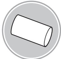
KIT0121003 0158x59mm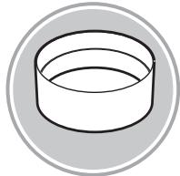
KIT0121006 90°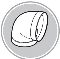
KIT0120991 222x89x1000mm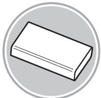
KIT0121001 227x94x80mm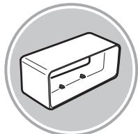
KIT0121004 90° 227x288x94mm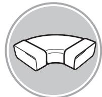
KIT0121005 90° 227x94mm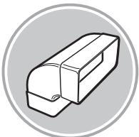
KIT0121008 227x94 - 0153mm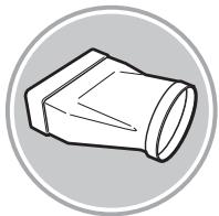
KIT0121010 190x190 - 0147mm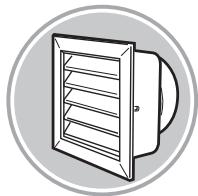
KIT0121009 INT 216X82mm EXT 290X160mm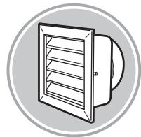
KIT0121002 15° - 227x94mm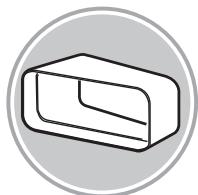
KIT0126810 227x94mm


4x03,5x9,5mm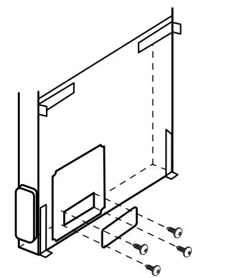

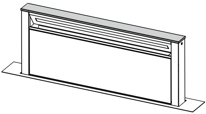

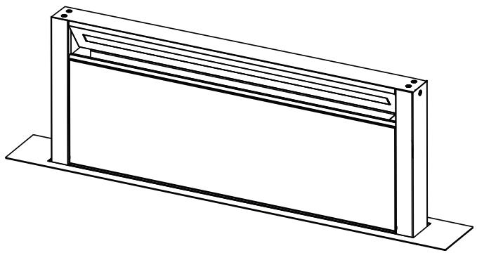


A
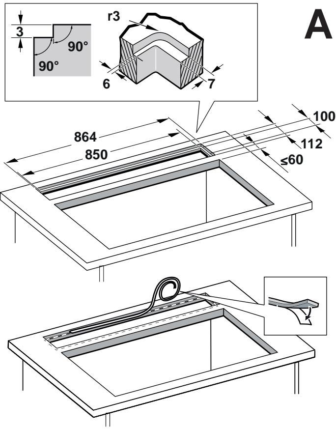
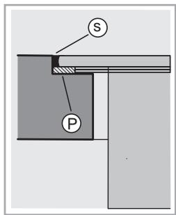
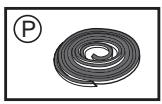
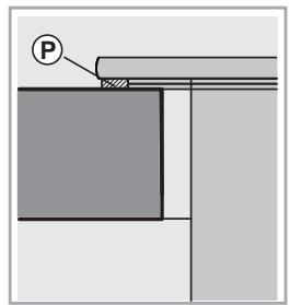
2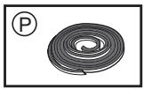
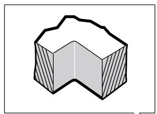
B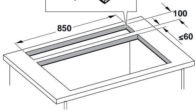

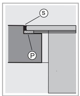
A
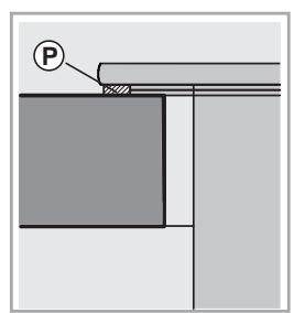
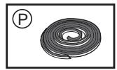
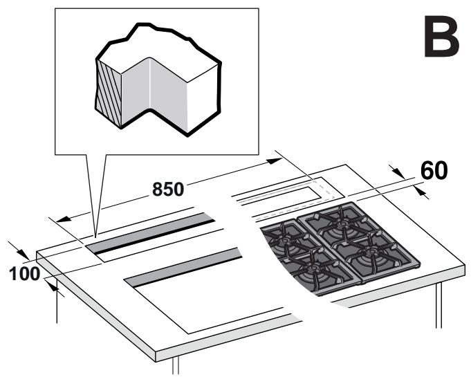


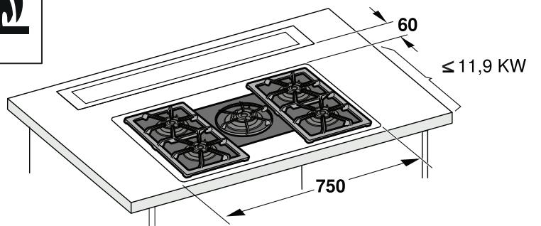
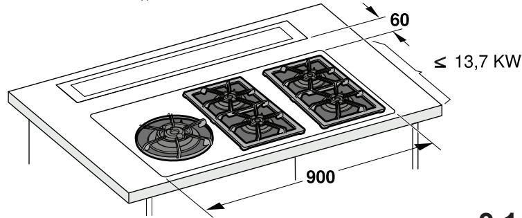
3.1
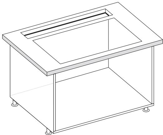
4
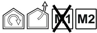
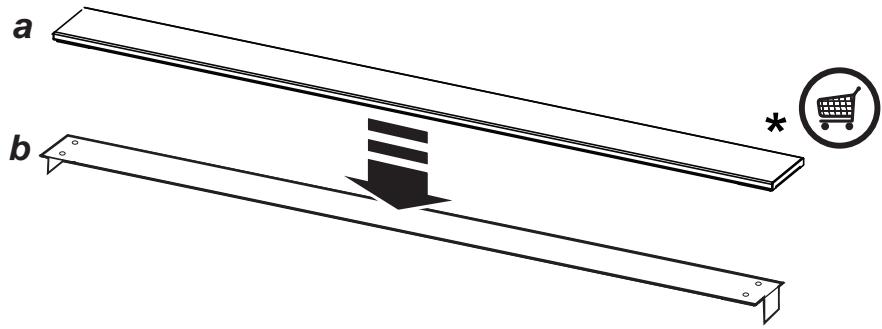
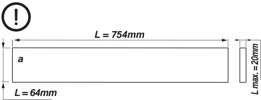
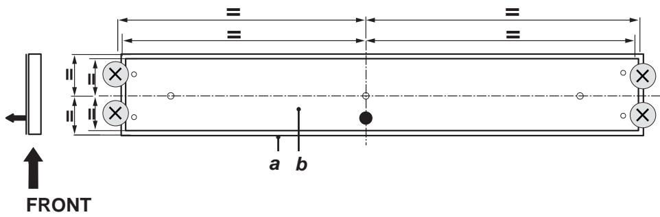
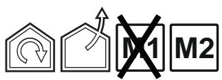
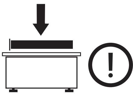
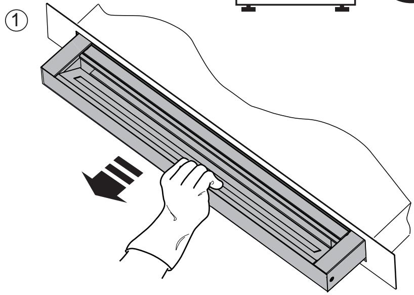
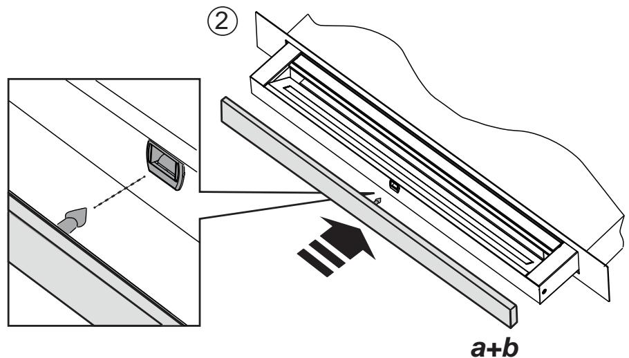
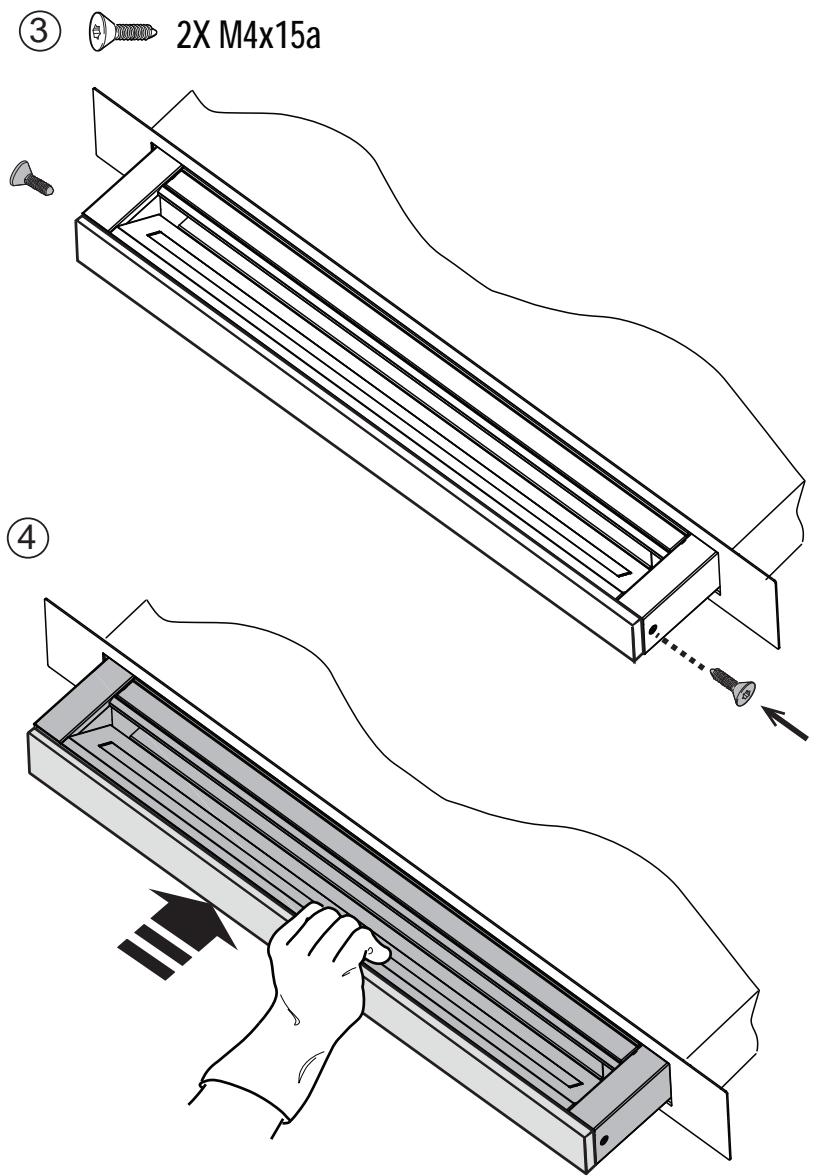



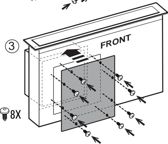
FRONT
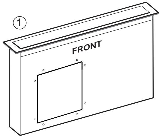
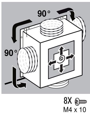
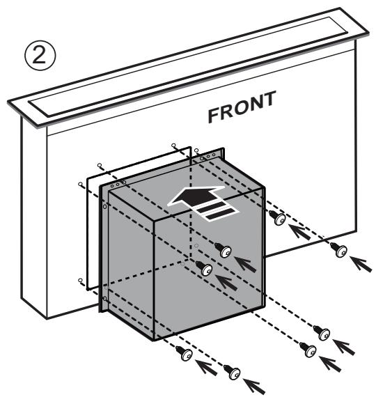
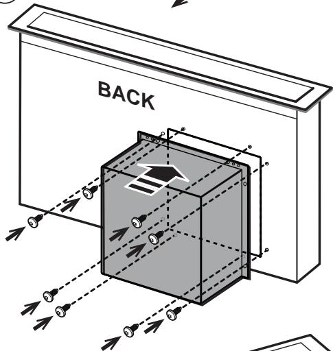
BACK
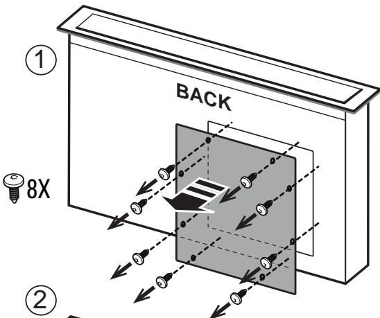
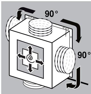
8X
M4 x 10

4X M4X10
14.1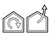

14.2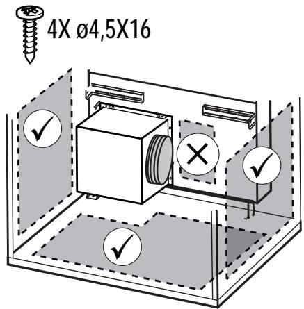


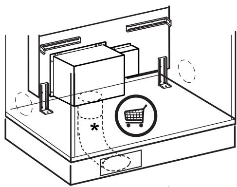
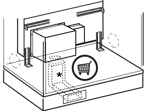
15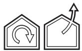
16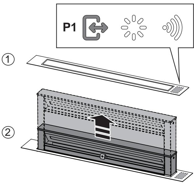
17 18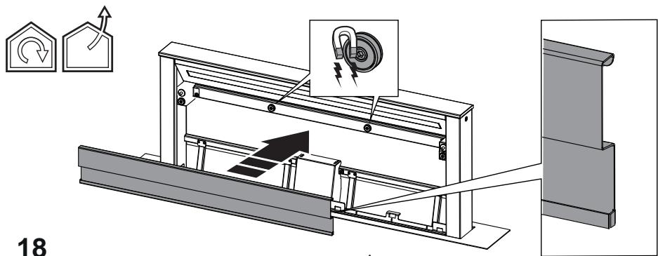


20



EN "Download the ELICA CONNECT APP to enjoy all the advantages of your connected product. Follow the instructions in the leaflet attached to the product"
EN "You can control your Elica hood with voice commands. Use the ELICA CONNECT APP to discover which voice assistants your hood is compatible with."
Closely follow the instructions set out in this manual. All responsibility, for any eventual inconveniences, damages or fires caused by not complying with the instructions in this manual, is declined. This appliance is intended to be used in household and similar application such as: - staff kitchen areas in shop, offices and other working environments; - farm houses; - by clients in hotels, motels and other residential type environments; - bed and breakfast type environments.
The hood can look different to that illustrated in the drawings in this booklet. The instructions for use, maintenance and installation, however, remain the same.
It is important to conserve this booklet for consultation at any moment. In the case of sale, cession or move, make sure it is together with the product. - Read the instructions carefully: there is important information about installation, use and safety. - Do not carry out electrical or mechanical variations on the product or on the discharge conduits. Before proceeding with the installation of the appliance verify that there are no damaged all components. Otherwise contact your dealer and do not proceed with the installation.
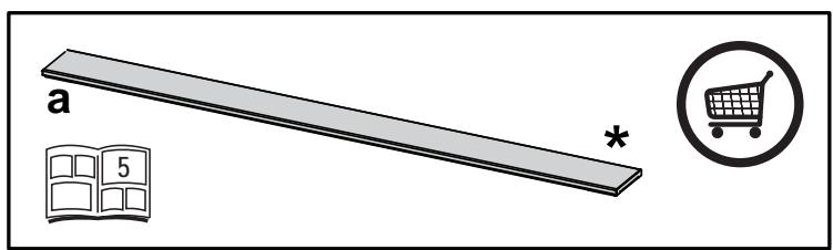
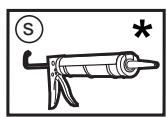
Note: The parts marked with the symbol "(*)" are optional accessories supplied only with some models or otherwise not supplied, but available for purchase.
Caution
- Before any cleaning or maintenance operation, disconnect hood from the mains by removing the plug or disconnecting the mains electrical supply.
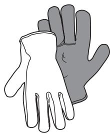
- Always wear work gloves for all installation and maintenance operations.
- This appliance can be used by children aged from 8 years and above and persons with reduced physical, sensory or mental capabilities or lack of experience and knowledge if they have been given supervision or instruction concerning use of the appliance in a safe way and understand the hazards involved.
- Children shall not be allowed to tamper with the controls or play with the appliance.
- Cleaning and user maintenance shall not be made by children without supervision.
- The premises where the appliance is
installed must be sufficiently ventilated, when the kitchen hood is used together with other gas combustion devices or other fuels.
- The hood must be regularly cleaned on both the inside and outside (AT LEAST ONCE A MONTH).
- This must be completed in accordance with the maintenance instructions provided. Failure to follow the instructions provided regarding the cleaning of the hood and filters will lead to the risk of fires.
- Do not flambe under the range hood.
- Do not remove filters during cooking.
- For lamp replacement use only lamp type indicated in the Maintenance/Replacing lamps section of this manual.
The use of exposed flames is detrimental to the filters and may cause a fire risk, and must therefore be avoided in all circumstances.
Any frying must be done with care in order to make sure that the oil does not overheat and ignite.
CAUTION: Accessible parts of the hood may become hot when used with cooking appliances.
- Do not connect the appliance to the mains until the installation is fully complete.
- With regards to the technical and safety measures to be adopted for fume discharging it is important to closely follow the regulations provided by the local authorities.
- The air must not be discharged into a flue that is used for exhausting fumes from appliance burning gas or other fuels.
WARNING! Failure to install the screws or fixing device in accordance with these instructions may result in electrical hazards.
- Do not use or leave the hood without the lamp correctly mounted due to the possible risk of electric shocks.
- Never use the hood without effectively mounted grids.
- The hood must NEVER be used as a support surface unless specifically indicated.
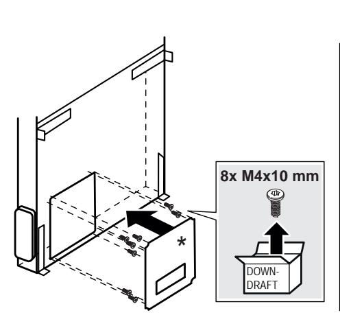
- Use only the fixing screws supplied with the product for installation or, if not supplied, purchase the correct screws type.
- Use the correct length for the screws which are identified in the Installation Guide.
- In case of doubt, consult an authorized service assistance center or similar qualified person.
WARNING! Do not use with a programmer, timer, separate remote control system or any other device that switches on automatically.
Electrical connection
The hood must be connected to the mains supply by qualified and trained technicians.
The mains power supply must correspond to the rating indicated on the plate situated inside the hood. If provided with a plug connect the hood to a socket in compliance with current regulations and positioned in an accessible area, after installation. If it not fitted with a plug (direct mains connection) or if the plug is
not located in an accessible area, after installation, apply a double pole switch in accordance with standards which assures the complete disconnection of the mains under conditions relating to over-current category III, in accordance with installation instructions.
WARNING! Before re-connecting the hood circuit to the mains supply and checking the efficient function, always check that the mains cable is correctly assembled.
Installation
If the instructions for installation for the gas hob specify a greater distance, this must be adhered to.
Note: The installation must be performed so that accessibility to the hood and its electronic components is always ensured for possible technical assistance interventions.
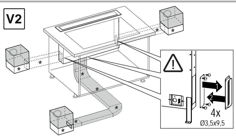
Note: the cable that connects the remote motor to the hood is 3 metres long
Caution! Do not cut the cable between the hood and the engine to avoid losing your right to warranty!
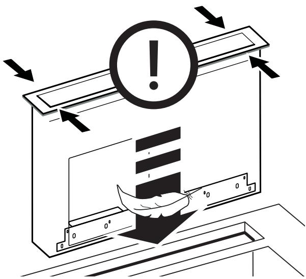
When handling the hood do not put hands within the range of action of the pull-out suction panel (trolley)
The hood is equipped with safety switches which inhibit operation when the front filter panel is unhooked.
With the intention of constantly improving our products, we reserve the right to make all the changes in their technical, functional or design characteristics, deriving from their evolution. In case of the version with external motor, the normal operation of the hood requires the use of a suction unit (external motor) of the same manufacturer.
When installing the product, it is recommended to keep a minimum distance of 400 mm between the worktop and any components laid on top of the hood.
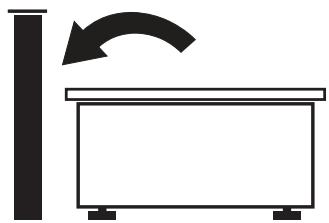
This is to let the suction panel move upwards (opening) and downwards (closing) without any obstacles, and to facilitate access to the hood controls on the panel.
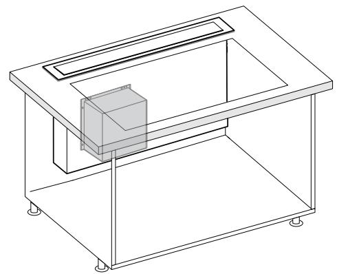
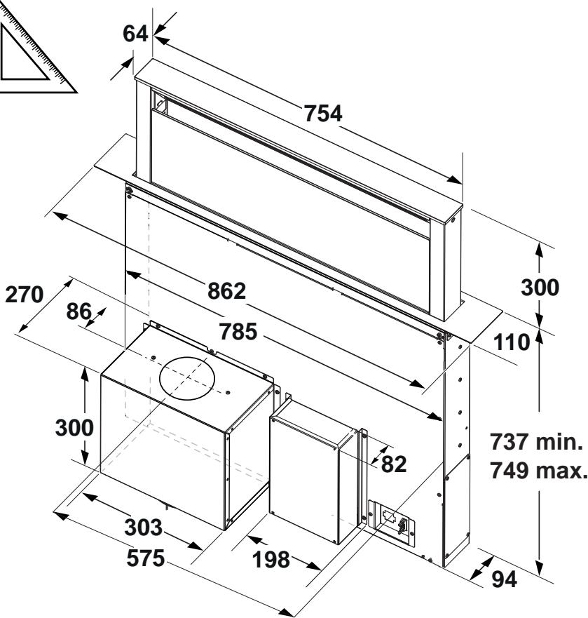
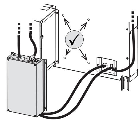
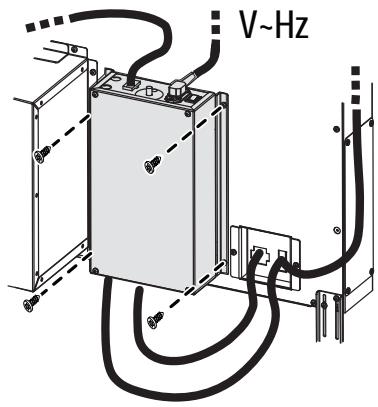
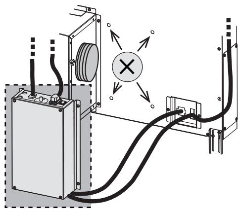
WARNING: Put the metal box containing the electronic components at a distance not shorter than 65 cm from the gas hob or 65 cm from the hood suction point.
RECOMMENDATION: We recommend you to install the metal box containing the electronic components at a distance of at least 10 cm from the ground and sufficiently from all the sources of heat (e.g.: side of an oven or hob).
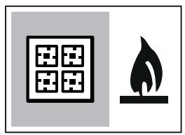
GAS COOKTOP:
All gas cooktops must not exceed the following values:
Maximum total power as in fig.3 and max 5 single burners.
A 75cm gas cooktop must not exceed the following values:
Maximum total power 11.9 KW; maximum total power of rear hobs: 4.7 KW; maximum power of wok 4.2 KW. A 90 cm gas cooktop must not exceed the following values: Maximum total power 13.7 KW; maximum total power of rear hobs: 4.7 KW; maximum power of wok 6 KW.
- Range hoods and other cooking fume extractors may adversely affect the safe operation of appliances burning gas or other fuels (including those in other rooms) due to back flow of combustion gases. These gases can potentially result in carbon monoxide poisoning. After installation of a range hood or other cooking fume extractor, the operation of flued gas appliances should be tested by a competent person to ensure that back flow of combustion gases does not occur.
- This appliance is marked according to the European directive 2012/19/EC - UK SI 2013 No.3113 on Waste Electrical and Electronic Equipment (WEEE).
- By ensuring this product is disposed of correctly, you will help prevent potential negative consequences for the environment and human health, which could otherwise be caused by inappropriate waste handling of this product.

- The symbol on the product, or on the documents accompanying the product, indicates that this appliance may not be treated as household waste. Instead it should be taken to the appropriate collection point for the recycling of electrical and electronic equipment. Disposal must be carried out in accordance with local environmental regulations for waste disposal.
- For further detailed information regarding the process, collection and recycling of this product, please contact the appropriate department of your local authorities or the local department for household waste or the shop where you purchased this product.
Appliance designed, tested and manufactured according to:
- Safety: EN/IEC 60335-1; EN/IEC 60335-2-31, EN/IEC 62233. Performance: EN/IEC 61591; ISO 5167-1; ISO 5167-3; ISO 5168; EN/IEC 60704-1; EN/IEC 60704-2-13; EN/IEC 60704-3; ISO 3741; EN 50564; IEC 62301.
- EMC: EN 55014-1; CISPR 14-1; EN 55014-2; CISPR 14-2; EN/IEC 61000-3-2; EN/IEC 61000-3-3; ETSI EN 301 489-1; ETSI EN 301 489-17; ETSI EN 300 328; IEC 62311:2019.
Suggestions for a correct use in order to reduce the environmental impact: Switch ON the hood at minimum speed when you start cooking and kept it running for few minutes after cooking is finished. Increase the speed only in case of large amount of smoke and vapor and use boost speed(s) only in extreme situations. Replace the charcoal filter(s) when necessary to maintain a good odor reduction efficiency. Clean the grease filter(s) when necessary to maintain a good grease filter efficiency. Use the maximum diameter of the ducting system indicated in this manual to optimize efficiency and minimize noise.
Use
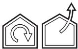
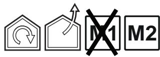
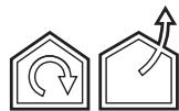
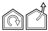
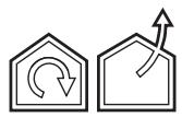
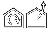
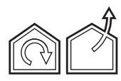
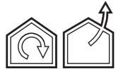
The hood is designed to be used either for exhausting or filter version.

Extraction version
In this case the fumes are conveyed outside of the building by means of a special pipe connected with the connection ring located on top of the hood.

CAUTION!
The exhausting pipe is not supplied and must be purchased apart.
Diameter of the exhausting pipe must be equal to that of the connection ring.

CAUTION!
If the hood is supplied with active charcoal filter, then it must be removed.

Filtration version
The aspirated air will be degreased and deodorised before being fed back into the room.
In order to use the hood in this version, you have to install a system of additional filtering based on activated charcoal.
Note: The recycled air in the charcoal filter is sent back to the kitchen through a duct which conveys air on a side of the cabinet.
The models with no suction motor only operate in ducting mode, and must be connected to an external suction device (not supplied).
The connecting instructions are supplied with the peripheral suction unit.
Mounting
Before starting to mount the appliance, make sure that no component is damaged, otherwise contact the dealer and stop mounting. In addition, read all the instructions below carefully.
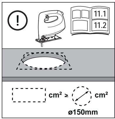
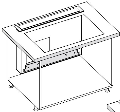
Use an air outlet pipe no longer than 5 metres. Limit the number of curves in the duct since each curve reduces the suction effectiveness equivalent to 1 linear metre. (E.g.: if two 90° curves are used, the duct should be no longer than 3 metres). Avoid drastic changes of direction. Use a duct with 150mm diameter constant for the whole length. Use a duct made of standard complying material. In case of failure to observe the instructions above, the supplier cannot be held responsible for capacity or noise problems and no warranty will be granted. Before making the hole, make sure that the inside of the cabinet, near the hood housing area, does not have the structure of the cabinet or other particulars which may cause problems for the proper installation. Make sure that the overall dimensions of the hood and the hob are compatible with the cabinet and therefore the installation is feasible.
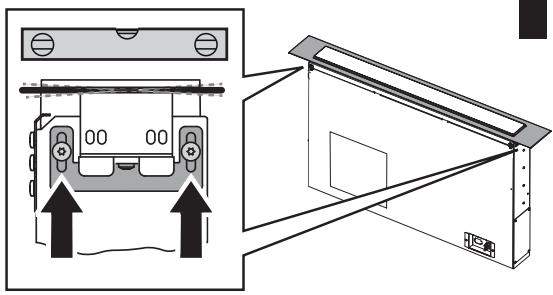
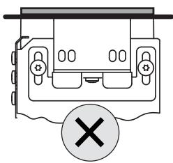
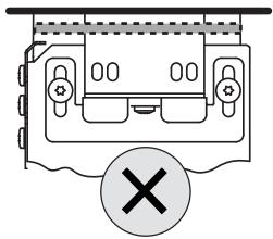
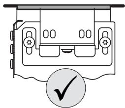
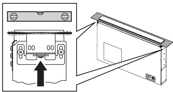
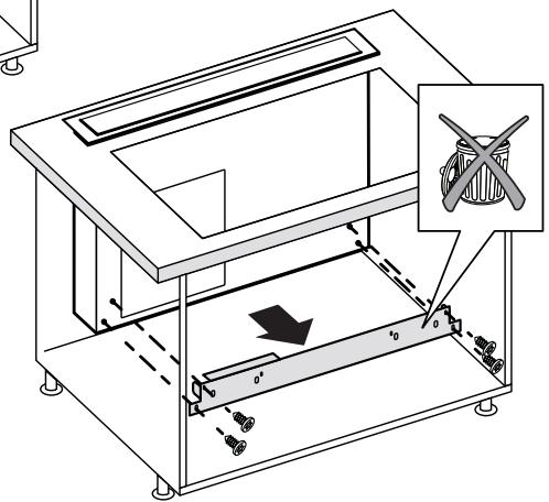
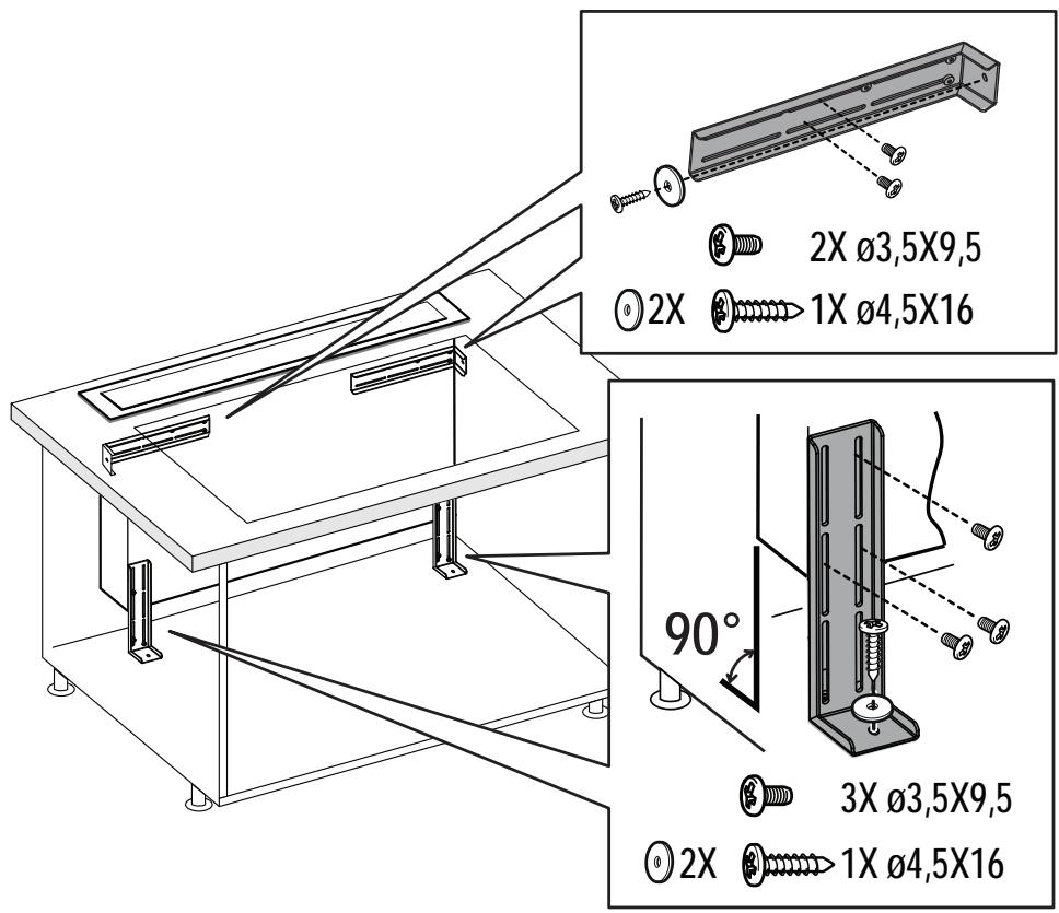
Before inserting the screws into the cabinet, make sure that the product is perfectly perpendicular to the worktop.
Panel Assembly
(only for models where the panel is not supplied with the hood)
CAUTION!
Installation must be carried out only by qualified installers.
FOR THE INSTALLER: Responsibility for installation of the hood, including verification of the conformity of any fixing kit supplied with the product, is the sole responsibility of the installer. Following is a non-exhaustive list of helpful instructions for the installer:
- use a fireproof PANEL (compliant with art. 30 of IEC/EN 60335-2-31), suitable for the operating temperature (at least 80°C) and humidity (at least 93%) reached during use;
- total weight of PANEL used should not exceed 1.5 kg
- secure the PANEL to the hood using the fixing points. See the illustrations dedicated to assembly of the panel not supplied with the hood.
- use suitable mechanical parts to fix the PANEL (not included in the assembly kit). Elica denies all liability for damage to persons or property resulting from incorrect installation of the gypsum panels and/or product.
Elica Connect
The hood features a WiFi function for remote connection via the Elica Connect app.
Minimum system requirements:
2.4GHz WiFi b/g/n wireless router Android or iOS Smartphone. Via the stores, check that the app is compatible with the operating system your Smartphone is running.
Note: The ELICA manufacturer declares that this model of household appliance with WiFi module radio equipment complies with Directive 2014/53/EU.
The radio equipment operates within the 2.4GHz ISM frequency band, the maximum radio frequency power transmitted does not exceed 20 dBm (e.i.r.p.).
Warnings:
Data protection. The data that the connected device detects is collected to allow for all the services of the connected appliance to be used. Further information on how the collected data is processed and on the privacy policy is available at www.elica.com. Availability in different countries. The Elica Connect service is available in specific countries. For further information, see the dedicated section at www.elica.com. Future changes. Elica reserves the right to make any changes deemed useful to improve the Elica Connect service. As a result, the descriptions contained in this manual are not binding and should be treated as purely indicative.
Operation
Control Display A
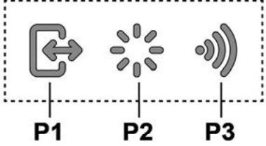
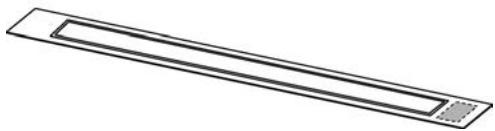
P1. Intake panel opening/closing button P2. Light ON/OFF button P3. WiFi connection button
P1. Intake panel opening/closing button
If the panel is CLOSED, by pressing button P1, the hood will turn on and the intake panel will be raised.
This operation will also give access to control display B, which manages motor and lighting.
If the panel is OPEN, by pressing button P1, the hood will turn off and the intake panel will be closed. This operation stops all active motor and lighting functions immediately.
Note: With the panel closed or while it is moving, control display B will remain deactivated. When the panel is completely open, it will be possible to use display B.
P2. Light ON/OFF button
If the panel is CLOSED, by pressing button P2, the hood will turn on, the intake panel will be raised and the lights will turn on only when the pull-out hood is completely open.
If the panel is OPEN, it will only be possible to turn the hood lights on and off.
Note: Light button P2 does not manage Light Dimming and does not turn the hood off.
P3. WiFi button
- WiFi configuration: if the WiFi function is not configured, press for about 2 seconds to enter WiFi configuration mode and follow the instructions on the App to complete the procedure.
During the configuration procedure, the button will light up indicating the connectivity status (see WiFi status table). To interrupt the WiFi configuration procedure, press for about 2 seconds when the button is lit up and is flashing fast.
Once the WiFi function has been configured, if you want to change it, press for about 6 seconds to reset the WiFi
parameters (the button will turn off) and repeat the configuration procedure.
- WiFi activation/deactivation: after the configuration, it is possible to deactivate/activate the WiFi function. Press for about 2 seconds to deactivate/activate the WiFi function.
Deactivating the function does not cause the loss of the WiFi parameters.
WiFi status table
| WiFi button | Device connection status |
| Light off | WiFi not configured or off |
| Light on steady | WiFi connected |
| Light flashing fast | Attempt to connect to the WiFi router |
| Light flashing slowly | Attempt to connect to the Elica cloud |
| Light on with short flashing light | Remote command being received (e.g. engine ignition or light turned on) |
Control Display B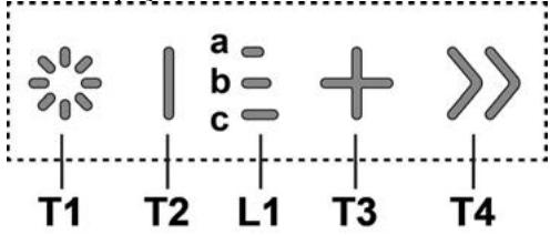
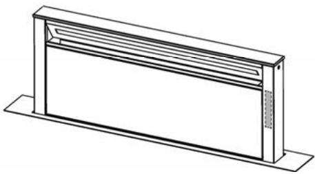
T1. Light ON/OFF button T2. Decrease intake speed / motor off button L1. Speed indicator LED on T3. Motor on / increase intake speed button T4. "BOOST" - intensive speed - function button
T1: Light ON/OFF button
to turn the light on and off.
Press and hold button T1 to increase / decrease the intensity of the light.
T2: Decrease speed / motor off button
Press to decrease the intake power until the extractor hood is turned off.
Press and hold to turn the hood off directly.
L1: Speed indicator LED on
The central LEDs light up according to the intake speed active/used:
1st speed, LED a will light up
2nd speed, LEDs a+b will light up
3rd speed, LEDs a+b+c will light up
T3: Increase speed button
Press to turn the hood on
Press to increase the intake power.
T4: "BOOST" - intensive speed - function button. Press T4 to activate the intensive intake speed "BOOST 1", timed for 30 minutes.
This prolonged timing has been designed to guarantee a suitable cooking time for preparations that release high amounts of smoke during cooking.
Note: After the 30 minutes, the hood will go back to the previously set intake speed ***.
With the motor on "BOOST 1", press T4 again to activate the intensive intake speed "BOOST 2", timed for 7 minutes.
Note: After the 7 minutes, the hood will go back to the previously set intake speed ***.
Note: press T4 again, during the 7 minutes, to go back to the previously set intake speed ***
with the "BOOST1" and "BOOST2" functions active, press:
T2 to go back to the previously set intake speed ***
T3 to go back to the 3rd intake speed
*** the previous intake speed remains visible via the indicator LEDs L1
if you have set the intensive speed directly with the hood off, the motor will be turned off after the set time.
While using the "BOOST" functions, the T4 symbol flashes ("BOOST 1": white light - "BOOST 2": blue light)
Filter Saturation indicator lights
At regular intervals, the hood signals the need to perform maintenance on the filters.
LED L1 (a-b-c) on and flashing light (all indicator lights flashing together): perform maintenance on the grease filter.
LED L1 (a-b-c) on and alternating light (the indicator lights turn on in sequence): perform maintenance on the active carbon filter
Note: The filter saturation indicator is visible within the first 10 seconds on turning on the hood; the saturation indicators must be reset within this time.
Reset filter saturation indicator:
Press and hold button T3
LED L1 (a-b-c) turns on and off (depending on the type of filter being reset, the indicator lights flash together or turn on in sequence); an acoustic signal will confirm the reset operation.
Activation of filter saturation indicator
Note: this operation must be performed with the hood off.
- Grease filter
This indicator is normally activated by a 1st prolonged press of buttons T3 and T2.
If the indicator is active, press button T3, then press button T2 to deactivate it. If the indicator is not active, press button T2, then press button T3 to activate it.
- Active carbon filter
This indicator is normally deactivated by a 2nd prolonged press of buttons T3 and T2.
If the indicator is active, press button T3, then press button T2 to deactivate it. If the indicator is not active, press button T2, then press button T3 to activate it.
Note: 3rd prolonged press of buttons T3 and T2.
Maintenance
Cleaning
Clean using ONLY a cloth dampened with neutral liquid detergent. DO NOT CLEAN WITH TOOLS OR INSTRUMENTS. Do not use abrasive products. DO NOT USE ALCOHOL!
Grease filter
Traps cooking grease particles.
This must be cleaned once a month (or when the filter saturation indication system - if envisaged on the model in possession - indicates this necessity) using non aggressive detergents, either by hand or in the dishwasher, which must be set to a low temperature and a short cycle.
When washed in a dishwasher, the grease filter may discolor slightly, but this does not affect its filtering capacity.
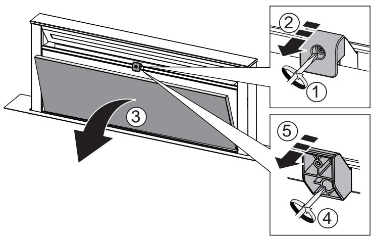
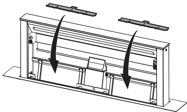
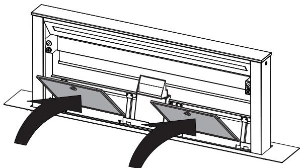
When inserting and removing grease filters and charcoal filters, please make sure that the extractable unit of the hood is in open position.
Then remove the front panel, by pulling on the upper part of each side at the same time.
The panel turns forward, so that grease filters can be inserted.
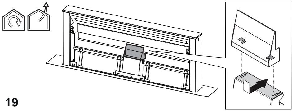
Fig. 18-21
Charcoal filter (filter version only)
It absorbs unpleasant odors caused by cooking.
Washable activated charcoal filter
The charcoal filter can be washed once every two months (or when the filter saturation indication system - if envisaged on the model in possession - indicates this necessity) using hot water and a suitable detergent, or in a dishwasher at 65°C (if the dishwasher is used, select the full cycle function and leave dishes out).
Eliminate excess water without damaging the filter, then put it in the oven for 10 minutes at 100°C to dry completely. Replace the mattress every 3 years and when the cloth is damaged.
After removing the grease filter, it is possible to insert the charcoal filters (not supplied).
Replacing lamps
The hood is equipped with a lighting system based on LED technology.
The LEDs guarantee an optimum lighting, a duration up to 10 times longer than the traditional lamps and allow to save 90% electrical energy.
To replace lights, contact authorised spare part center.
Activating filter saturation indicator
Press button 1 to turn on
Press button 2 to turn on a+b
Press button 3 to turn on a+b+c
T3: Press and hold
Instructions for replacing the filter
Instructions for cleaning the filter
- Activated carbon filter
This indicator is normally off. It lights up when the filters T3 and T2 need to be replaced.
If the indicator is on, press button T3 then button T2 to deactivate it. If the indicator is off, press button T2 then button T3 to activate it.
Display B for command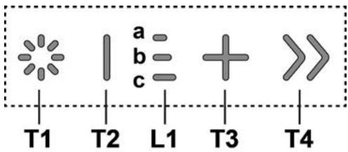
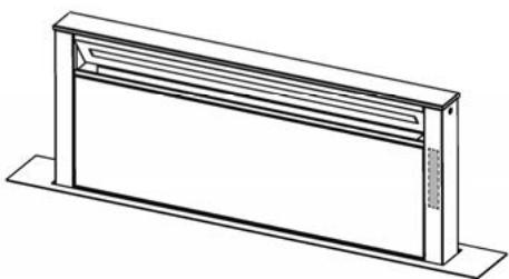
Press to turn on the appliance
Danger! Read the safety instructions carefully.
Do not let children play with the appliance! - Cleaning and maintenance must be performed by adults under supervision. - The appliance must be placed in a well-ventilated area when in use, away from gas or other flammable materials. - The appliance should be cleaned frequently, both inside and out (at least once a month). - Follow the instructions in the maintenance manual! - Failure to follow the cleaning instructions for the appliance and the filters may pose a fire risk. - Strictly forbidden is the preparation of flambé dishes under the appliance. To replace the lamps, use only those specified in the Lamps/Replacement section, as indicated in the operating manual. Using an open flame is harmful to the filters and may cause a fire, so it must be avoided at all times. Cooking with oil must be done under supervision, as overheated oil can ignite. WARNING: When the appliance is in operation, accessible parts may become hot. Do not connect the appliance to the mains until installation is completely finished.
- Regarding the technical dimensions and safety measures that must be taken for the installation of the appliance, we recommend that you strictly follow the rules set out in the regulations of the competent local authorities.
- The aspirator does not need to be connected to the appliance, the hoses used for exhausting the gases are separated from the use of the appliance with gas or other fuel. WARNING! Incorrect installation of the bolted mechanisms for fixing in accordance with these instructions may lead to risks of electric shock. Do not use or leave the aspirator without properly installed lamps due to the possible risk of electric shock.
- Never use the aspirator without a properly installed grille!
- The aspirator must never be used as a support surface unless this is specifically indicated.
- During installation, use only the self-tapping bolts that are supplied with the appliance, or if such are not available, purchase suitable bolts. Use bolts with the appropriate length, as indicated in the installation instructions.
- In case of replacement, please contact the authorized service for technical maintenance by qualified personnel.
WARNING! Do not use with a programmer, timer, remote control or any other device that activates automatically.
! Electrical connection
The connection to the electrical mains of the aspirator must be carried out by qualified and specialized technical personnel.
The mains plug must correspond to the plug indicated on the data plate of the aspirator, placed on its inner side. If it is equipped with a plug, connect the aspirator to a socket corresponding to the current standards and make sure it is easily accessible after installation. If it is not equipped with a plug (direct connection to the mains), or if the plug is not easily accessible after installation, use a bipolar switch with a contact opening of at least 3 mm, in accordance with the installation rules.
WARNING! Before connecting the aspirator to the mains and checking that it functions properly, check that the cable is installed as it should be.
Installation
If the instructions for the gas appliance for cooking indicate a greater distance, then it must be taken into account.
Precedence.
Note: Installation must be carried out in such a way that the non-return valves and electrical components are accessible for possible technical maintenance. Note: The cable connecting the motor to the aspirator is with a length of 3 m
WARNING! Do not connect the connection cable between the aspirator and the hob, so as not to lose the right to the warranty.
Before starting work on the aspirator, make sure that the device is disconnected from the power supply in the area where aspiration is performed, including the mechanism.
The aspirators are equipped with safety switches that stop its operation when the front panel is removed.
In order to constantly improve our products, we reserve the right to make changes to the technical and functional characteristics of the devices, as well as to the materials used, without prior notice. For models with an external motor, for proper operation of the aspirator, the suction unit (external motor) must be installed at the height indicated in the diagram.
When installing, we recommend leaving a minimum distance of 400 mm between the working surface and any flammable components located above the aspirator.
There should be no obstacles when moving the duct upwards (exhaust) and downwards (intake) of the aspiration duct, and the duct should be routed to the aspirator's controls located on the duct.
WARNING: Install the metal duct and electrical components at a distance of no less than 65 cm from gas outlets or, in any case, at least 65 cm from the aspiration grille.
RECOMMENDATION: We recommend installing the metal duct and electrical components at least 10 cm away from the surface and at a sufficient distance from any heat sources (for example, the side of a gas stove or cooktop).
Gas cooktop type:
Gas cooktops must comply with the following requirements: Maximum total power as indicated on the rating plate. Gas cooktops from 75 cm must not comply with the following requirements:
Maximum total power 11.9 kW; Maximum power of the rear gas burners: 4.7 kW; Maximum power of the front burners 4.2 kW. Gas cooktops 90 cm must not comply with the following requirements:
Maximum total power 13.7 kW; Maximum power of the rear gas burners: 4.7 kW; Maximum power of the front burners 6 kW.
This device complies with the requirements of:
- European Directive 2012/19/EC - UK SI 2013 No.3113
- Waste Electrical and Electronic Equipment (WEEE).
This product must not be disposed of as unsorted municipal waste. It must be collected separately for recycling. Please follow local regulations for waste disposal. For more information on the correct disposal, collection, and recycling of this product, please contact your local authorities, the waste collection service, or the store where you purchased this product.

This product must not be treated as household waste. It must be handed over to a designated collection point for the recycling of electrical and electronic equipment. Please follow local regulations for waste processing. For more detailed information on the disposal, collection, and recycling of this product, please contact your local authorities, the household waste collection service, or the store where you purchased this product.
The product is designed, tested, and manufactured in accordance with:
- Safety: EN/IEC 60335-1; EN/IEC 60335-2-31, EN/IEC 62233.
- Performance characteristics: EN/IEC 61591; ISO 5167-1; ISO 5167-3; ISO 5168; EN/IEC 60704-1; EN/IEC 60704-2-13; EN/IEC 60704-3; ISO 3741; EN 50564; IEC 62301.
- EMC - Electromagnetic compatibility: EN 55014-1; CISPR 14-1; EN 55014-2; CISPR 14-2; EN/IEC 61000-3-2; EN/IEC 61000-3-3; ETSI EN 301 489-1; ETSI EN 301 489-17; ETSI EN 300 328; IEC 62311:2019.
Recommendations for correct use to reduce environmental impact: Turn on the extractor at minimum speed when you start cooking and leave it running for a few minutes after cooking is finished. Increase the speed only in case of large amounts of smoke or steam, and use the boost speed only in extreme situations. Replace the grease filter when necessary to maintain good efficiency of the grease filter. Replace the carbon filter when necessary to maintain good efficiency of the carbon filter. Use the maximum diameter of the air exhaust system, as per this guide, to optimize efficiency and reduce noise.
Use
Extractors for specific use: They extract polluted air and filter it, while simultaneously recycling it.

Extractor with recirculation
The air is extracted and filtered through the air duct.
The exhaust pipe must be connected to the ventilation system.
WARNING!
The exhaust pipe is not included in the accessories and must be purchased separately.
The diameter of the exhaust pipe must correspond to the diameter of the connection pipe.
WARNING!
If the appliance is supplied with a plug and is connected, the pipe must be installed so that it can be removed.

Ventilation
The aspirated air is introduced into the room before entering the room and the room. To use the aspirator in this mode of operation, you must install an additional ventilation system on the base of the ventilation and the connected plug.
Note: The air that is recirculated from the ventilation plug is introduced into the room through the exhaust pipe, which is located on the side of the aspirator.
Models without aspiration are intended for operation only in the aspiration mode and must be connected to a non-continuous aspiration unit, which is purchased separately.
The instructions for connection are provided with the peripheral aspiration unit.
INSTALLATION
Before starting the installation of the device, check the data on its rating plate. If necessary, connect it to the power supply and start the installation. Follow all the instructions carefully.
- Use the exhaust pipe with a maximum length of 5 m. The minimum length of the pipe bends in the exhaust pipes is such that each pipe bend has a 1 m reduction in the capacity of the aspiration (for example: if there are 2 pipe bends with a 90° angle, the length of the exhaust pipes must not exceed 3 m.). Do not change the direction abruptly.
- Use pipes with a diameter of 150 mm for the connection. The material from which the pipes are made must comply with the current standards.
- The manufacturer declines all responsibility for any problems arising from the failure to install the appliance correctly, and consequently provides no guarantee. Before installing, make sure that on the inside of the cabinet, at the location where the appliance will be installed, there are no structural elements or other components that could obstruct the correct installation of the appliance. Make sure that the dimensions of the appliance and the mounting holes are compatible with those of the cabinet, and that there are no obstacles to installation. - First, position the screws in the cabinet, making sure that the hole is positioned perpendicular to the working hole.
Once the appliance is installed, the structure of the cabinet must not contain any other elements that could interfere with the correct installation of the appliance. Make sure that the dimensions of the appliance and the mounting holes are compatible with those of the cabinet, and that there are no obstacles to installation. - First, position the screws in the cabinet, making sure that the hole is positioned perpendicular to the working hole.
Panel mounting
(only for models where the appliance is not supplied with the panel)
WARNING!
Installation must be carried out exclusively by qualified technicians. For the appliance: the manufacturer is not liable for the installation of the appliance, including the verification of the conformity of the fixing kit, which may be included with the product. In the following, only general information is provided, and the specific installation instructions are presented:
The panel must be suitable for the working temperature (up to 80°C) and humidity (up to 93%) conditions; - the weight of the panel must not exceed 1.5 kg; - fix the panel to the appliance using the fixing screws. See the illustrations for the panel mounting, which are not supplied with the appliance. - For fixing the panel, use suitable mechanical components (if not included in the mounting kit). Any damage to the panel or the product due to incorrect installation is the sole responsibility of the user.
Elica Connect
Connect the appliance with WiFi function for remote connection via the Elica Connect app.
Minimum system requirements:
Router 2.4GHz WiFi b/g/n, smartphone Android or iOS. Check the app stores for compatibility of the app with your smartphone's operating system version.
Note: The manufacturer ELICA declares that this model is equipped with radio equipment with WiFi module in compliance with Directive 2014/53/EU.
The radio equipment operates in the frequency range of 2.4GHz, with a maximum transmitted radio power not exceeding 20 dBm (e.i.r.p.).
Precautions:
Data protection. Data collected by the device are processed to allow the use of all connected functions. For more information on how collected data are processed, you can visit the website www.elica.com. Availability of the service. The Elica Connect service is offered in certain countries. For more information, visit the dedicated website www.elica.com. Changes. Elica reserves the right to make any changes it deems useful for improving the Elica Connect service. Therefore, the descriptions contained in this manual are not binding and have no contractual value.
Haun Ha ynoTpe6a
Control Panel
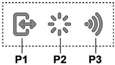
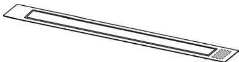
P1. Button for opening/closing the extraction panel. P2. Light button ON/OFF P3. WiFi button
P1. Button for opening/closing the extraction panel
If the panel is CLOSED, by pressing button P1 the extractor will turn on and the extraction panel will open.
This operation will not affect the control panel, which controls the motor and the lighting.
If the panel is OPEN, pressing button P1 will close the flap, which will close the extraction panel. This operation will not affect the motor lighting function.
Note: When the panel is closed and the flap is open, the control panel will remain off. When
the panel is fully open, it will be possible to use the control panel.
P2. Light button ON/OFF
If the panel is CLOSED, by pressing button P2 the extractor will turn on, the extraction panel will open, and the lights will turn on, but only when the flap is fully open.
If the panel is OPEN, only the switching on and off of the extractor's lighting can be controlled.
Note: The light button P2 does not control the dimming of the lights and does not control the switching off of the extractor.
P3. WiFi button
- WiFi configuration: If the WiFi function is not configured, press for about 2 seconds to enter configuration mode: WiFi and follow the instructions of the app to complete the procedure.
During the procedure for configuring the light button, the connection status is shown (see the WiFi status table).
To start the WiFi configuration procedure, press for about 2 seconds when the light button emits a flashing light.
After configuring the WiFi function, if you want to change it, press for about 2 seconds to enter the WiFi parameters (the button lights up) and repeat the configuration procedure.
- Activate/deactivate WiFi: After configuration, you can deactivate/activate the WiFi function. Press for about 2 seconds to deactivate/activate the WiFi function. Deactivating the function leads to loss of WiFi parameters.
WiFi status table
Use only mild detergents and clean the dishwasher with a damp cloth. However, at high temperature, a short wash cycle is recommended.
The use of rinse aid in the dishwasher is possible, but it does not in any way replace the need for filtering.
The installation and removal of the filter for the dishwasher is carried out through the opening in the lower part of the spray arm mechanism.
After that, remove the sieve plate by pulling it up and simultaneously from both sides. The filter will be released and you can access the filter for the dishwasher.
Fig. 18-21
Filter with active carbon (only for filtering version)
Hold the front panel, which separates when pressed.
Place the active carbon filter
The active carbon filter can be replaced every two months or when the indicator for filter replacement (if your model is equipped with one) shows. Use only suitable detergent for dishwashers and at 65°C. In any case, the dishwasher must not have other dishes and must run a wash cycle.
Rinse the filter thoroughly, then place it back in the holder for about 10 minutes at 100°C
The carbon filter must be replaced every 3 years or if the surface is damaged.
After removing the filters for the grease, it is possible to install the filters with active carbon (which are not supplied with the appliance).
Top of the appliance. Screws
The appliance has a lighting system with LEDs.
The LEDs guarantee optimal lighting, up to 10 times stronger than traditional lamps and allow 90% energy savings.
To replace the lamps, contact the after-sales service for spare parts.
The device has been designed, tested and manufactured in accordance with:
- Safety: EN/IEC 60335-1; EN/IEC 60335-2-31, EN/IEC 62233.
- Performance characteristics: EN/IEC 61591; ISO 5167-1; ISO 5167-3; ISO 5168; EN/IEC 60704-1; EN/IEC 60704-2-13; EN/IEC 60704-3; ISO 3741; EN 50564; IEC 62301. EMC: EN 55014-1; CISPR 14-1; EN 55014-2; CISPR 14-2; EN/IEC 61000-3-2; EN/IEC 61000-3-3; ETSI EN 301 489-1; ETSI EN 301 489-17; ETSI EN 300 328; IEC 62311:2019.
Suggestions for correct use to reduce impact on the environment: Turn on the hood at minimum speed when you start cooking and leave it running for a few minutes after you finish cooking. Increase the speed only in case of a large amount of smoke and use the boost speeds only in extreme situations. Replace the charcoal filter(s) when necessary to maintain good odor reduction efficiency. Clean the grease filter(s)
when necessary to maintain good grease filter efficiency. Use the maximum diameter of the air exhaust system, as indicated in this manual, for optimal efficiency and minimization of noise levels.
Use
The hood is designed for intermittent operation of air extraction or air recirculation.

Use of the appliance in extraction mode
In this operating mode, the air is expelled outside through the pipes connected to the collar.

ATTENTION!
The exhaust pipe is not included in the kit and must be purchased separately.
The diameter of the exhaust pipe must match the diameter of the connecting ring.

ATTENTION!
If the hood is equipped with a charcoal filter, make sure it is installed.

Use of recirculation
air
A charcoal filter, available from your distributor, must be used. The air is deodorized and purified before being returned to the room through the upper grille.
Usage: Air filtered by the charcoal filter is returned to the kitchen through the air outlet, which draws air through one of the side panels of the kitchen unit.
Models without a motor block can operate in one mode of air extraction to the outside, so they must be connected to an external exhaust system (not included).
Connection instructions are supplied with the external exhaust unit.
Installation
Before starting installation, check that all components are not damaged; otherwise, contact the point of sale before proceeding with installation. Also, carefully read all instructions supplied with the product.
Use an exhaust pipe no longer than 5 meters. Limit the number of bends in the duct, as each bend reduces suction efficiency equivalent to 1 linear meter. (For example, if a 90° bend is used, the duct length must not exceed 3 meters).
If a 90° bend is used, the duct length must not exceed 3 meters.
- Sharp changes in direction. Use an air duct with a diameter of 150 mm along its entire length. Use an air duct made of materials approved by standards. In case of failure to comply with the above instructions, the manufacturer shall not be liable for problems related to the hood's performance or noise, and the warranty shall not be provided.
- Before drilling the hole, check that there are no pipes or cables in the wall behind the installation area, nor any structural elements or other parts that could interfere with proper installation.
Check that the overall dimensions of the hood and the mounting surface match the dimensions of the kitchen furniture, and thus the possibility of performing the installation.
- Before inserting the flue into the hood, check that the product is perpendicular to each surface.
INSTALLING THE FLUE
(ONLY FOR MODELS WHERE THE FLUE IS NOT PROVIDED WITH THE EXTRACTION KIT)

WARNING!
Installation must be carried out only by qualified technicians. FOR THE INSTALLER: Responsibility for the installation of the hood, including verification of the fastening kit, if supplied with the product, lies with the installer. Below are some examples and non-exhaustive instructions for the installer:
Use a flue of the fire-resistant type (in accordance with IEC/EN 60335-2-31), suitable for the working conditions in terms of temperature (not less than 80°C) and humidity (not less than 93%), achievable when: - the weight of the flue used is not more than 1.5 kg; - the flue is fixed to the extraction kit at the fixing points. See the instructions for installing the flue, not provided with the extraction kit. - Use suitable mechanical elements for fixing the flue (not included in the installation kit). The company Elica disclaims all liability for damage caused to persons or property due to incorrect installation of the flue and/or the product.
Elica Connect
The extraction kit is equipped with a WiFi function for remote connection via the Elica Connect app.
Minimum system requirements:
Wireless router 2.4 GHz WiFi standards b/g/n. Smartphone with Android or iOS. Check on the app stores the compatibility of the app with your operating system and smartphone.
Required information:
Data processing and protection. Data collected by the connected device is used to ensure the full functionality of the hood and the correct operation of the electric motor. More detailed information on the use of collected data and the privacy policy is available on the website www.elica.com. Availability in different countries. The Elica Connect service is available in a number of specific countries. More details can be found in the dedicated section of the website www.elica.com. Future modifications. The company Elica reserves the right to make all changes deemed necessary for the improvement of the Elica Connect service. Therefore, the descriptions and illustrations in this user manual are not binding and are for informational purposes only.
Operation
Press the power button to turn the device on or off.
Press and hold to immediately turn off the exhaust hood.
L1: Light indicator - speed setting
The central indicator lights turn on depending on the selected speed:
Speed 1 - indicator light a; Speed 2 - indicator lights a+b; Speed 3 - indicator lights a+b+c
T3: Speed increase button
Press to turn on the exhaust hood.
Press to increase the exhaust power.
T4: "BOOST" function button - increased speed levels -
Press button T4 to activate the increased exhaust speed "BOOST 1", which will be active for 30 minutes.
This function is designed to ensure sufficient time for preparing large quantities of food.
Note: After 30 minutes, the exhaust speed will return to the previously set value ***
While the motor is operating in "BOOST 1" mode, press button T4 again to activate the increased exhaust speed "BOOST 2", set for a duration of 7 minutes.
Note: After 7 minutes, the exhaust speed will return to the previously set value ***
Note: If the button T4 is pressed again, within an interval of 7 minutes, the extraction speed will return to the level that was previously set ***
If the functions "BOOST1" and "BOOST2" are active, when pressing:
T2 returns to the previously set speed ***
T3 returns to the 3rd extraction speed *** The previous extraction speed is still indicated by the LEDs L1
If the set speed is exceeded with the extraction hood on, after the corresponding interval, the motor turns off.
When using the "BOOST" function, the T4 symbol lights up ("BOOST 1": white light - "BOOST 2": blue light)
Filter clogging indicator
After certain time intervals, the extraction hood signals the need for filter maintenance.
LED L1 (a-b-c) lights up with a steady light (all LEDs - blue - light up together): Perform maintenance of the washable filter.
LED L1 (a-b-c) lights up alternately (LEDs light up sequentially): Perform maintenance of the filter with activated carbon
Note: The clogging indicator appears for the first 10 seconds after turning on the extraction hood. During this interval, check the clogging indicators.
Reset of the filter clogging indicator:
Washable filter
- These must be under control and must not be damaged.
Maintenance operations must not be performed without a load.
When using the hood, it is necessary to ensure sufficient ventilation in the room. The hood can be used simultaneously with other gas or fuel-burning appliances.
- The hood should be cleaned frequently both inside and outside (at least once a month). Follow the maintenance instructions provided.
Failure to replace or clean the filters increases the risk of fire.
It is strictly forbidden to cook with an open flame under the hood.
Only use the lighting with the specified type of lamp as indicated in the maintenance/lamp replacement section.
Using an open flame with the filters can lead to fire, so it is necessary to avoid it in any case.
Maintenance should be carried out by qualified personnel to avoid any risk.
WARNING: Accessible parts may become hot when used with gas appliances.
Do not connect the appliance to the electrical supply until the installation is fully completed. This concerns technical and safety measures during use.
Regarding the connection of vapors, strictly follow the standards of local competent authorities.
The air extracted must not be discharged into a flue used for exhaust fumes from gas or other fuel-burning appliances.
WARNING! Failure to install the appropriate screws and devices in accordance with these instructions may result in electrical hazards.
Do not use or leave the hood without correctly installed lamps, as there is a risk of electric shock.
- Never use the hood without the correctly installed grille!
- The exhaust hood must not be used on a support surface unless it is level.
Using screws for fixing in a set with a product that is not included in the set, try screws of the correct type.
Use the correct type of screws as indicated in the installation manual.
- In case of doubt, consult the authorized service center or qualified personnel.
WARNING! Do not use with a programmer, timer, separate remote control or any other device that activates automatically.
Electrical connection
Connection of the exhaust hood to the electrical network must be performed
by qualified and trained personnel.
The voltage in the electrical network must correspond to the characteristics indicated on the label located inside the hood. If the kit includes a plug for connecting to the electrical network, then after connecting the hood to the socket, which corresponds to existing standards and is located in an accessible place, it is possible to perform after installation. If the plug is not included in the kit (direct connection to the electrical network), or the socket is not in an accessible place, then after installation, a suitable two-pole switch must be installed, which ensures complete disconnection from the network under conditions of overvoltage category III, in full compliance with installation rules.
WARNING! Before connecting the hood to the electrical network again, check the correctness of operation, by controlling that the network switch is installed correctly.
Installation
It is necessary to take into account the installation instructions for the installation of the hood.
Note: The installation must be carried out in such a way that free access to the hood and to the electrical components is guaranteed for possible work on technical maintenance.
Note: The cable, which is supplied with the hood, must have a length of 3 m.
Please connect the cable between the hood and the hob to avoid losing the right to warranty.
Under the hood, keep the working range of the appliance at least 65 cm (see figure).
The hood is equipped with safety devices that
recommend work, when the filter is removed from the printer.
By applying the product, we reserve the right to make technical, functional or aesthetic changes to it during its production. For hoods with an external motor, for normal operation it is necessary to use the connection block (external motor) of the same manufacturer.
When installing the hood, maintain a minimum distance of 400 mm between the work surface and the components located above the hood cover.
This is necessary so that when the hood is fully open (opening and closing the panel) there are no obstacles and for easy access to the control keys located on the panel.
WARNING: Install a metal frame in the place where the electronic components are located at a distance of not less than 65 cm from the gas surface and in this device at a distance of 65 cm from the connection point of the hood cover.
ADVICE: It is recommended to install a metal frame with electronic components at a distance of not less than 10 cm from the floor and at a sufficient distance from all present heat sources (e.g., oven side and gas surface).
GAS SURFACE:
All gas surfaces must not exceed the following values: Total maximum power, as indicated in Fig. 3, and max. 5 separate burners. - Gas surface size 75 cm must not exceed the following values: Total maximum power 11.9 kW. Total maximum power of rear surfaces: 4.7 kW. Maximum power of the burner 4.2 kW. - Gas surface size 90 cm must not exceed the following values: Total maximum power of rear surfaces: 4.7 kW. Maximum power of the burner 6 kW.
This product has been marked in accordance with European Directive 2012/19/EC - UK SI 2013 No.3113, regarding waste electrical and electronic equipment (WEEE). By ensuring proper disposal of this product, you will help prevent potential negative consequences for the environment and human health, which could otherwise be caused by inappropriate handling of this product.

The symbol on the product or on its accompanying documentation indicates that this product must not be treated as household waste. It should be handed over to the appropriate collection point for the recycling of electrical and electronic equipment.
Disposal. All waste must be carried out in accordance with local regulations for waste disposal. For detailed information on the treatment, recovery and recycling of this product, please contact your local city office, your household waste disposal service or the shop where you purchased the product.
The device was designed, tested and manufactured in accordance with:
- Standards: EN/IEC 60335-1; EN/IEC 60335-2-31, EN/IEC 62233.
- Performance: EN/IEC 61591; ISO 5167-1; ISO 5167-3; ISO 5168; EN/IEC 60704-1; EN/IEC 60704-2-13; EN/IEC 60704-3; ISO 3741; EN 50564; IEC 62301. EMC: EN 55014-1; CISPR 14-1; EN 55014-2; CISPR 14-2; EN/IEC 61000-3-2; EN/IEC 61000-3-3; ETSI EN 301 489-1; ETSI EN 301 489-17; ETSI EN 300 328; IEC 62311:2019.
For proper use and maintenance: Turn the hood on at minimum speed before starting to cook, and let it run for a few minutes after cooking. Increase the speed when cooking large amounts of food, and use the boost speed in extreme cases. Maintain high efficiency of odor extraction; if necessary, replace the charcoal filter(s). Maintain high efficiency of the grease filter; if necessary, clean the grease filter(s). Use the maximum diameter of the duct system as indicated in the instructions for optimal efficiency and minimal noise.
Use
The hood is designed for use in recirculation mode, drawing air through the charcoal filter.

Extraction version
When extracting air through the exhaust pipe, the hood is connected to the outside.

WARNING!
The exhaust pipe is not supplied and must be purchased separately.
The diameter of the exhaust pipe must match the diameter of the connection ring.

WARNING!
If the exhaust hood has charcoal filters, they must be removed.

Recirculation version
The air is purified and then returned to the room. To use the hood in this mode, an additional filter system with activated carbon must be installed.
charcoal.
Ppimitka: Nobitr npophiIbTpoBaHe uepe3 pfIbTp akTnBOaHOrO ByrInnNoBepTaEcBcHa KxHIO uee3 KaHan, kMy nepenyckaNobitrpo BHXoDntb Ha OndH CTopoHi Kopnycy.
MoJIeI KOBnakIB 6e3 MOTOPHO 6NOKy MOKYb IpaUOBaTINIe B ODHOMY peKIMi BiDbOy NOBITpR Ha3OBHi, TOMY NOBHHI 6ytN NiID'EnHAI Do 3OBHIuHbOi BNTJXHOY UCTaHOBKn (HE BXoDHTB B NOCTABK).
IHTpykii 10oPiEcdHaHHnoCTaHOTbc3 npneepiHMM 6bnaHaHHM.
Inctanlaic
Iepu hix ponoatn BCTaHOBHeHna apaTy, nepebiTe, 0o6 BcI KOMIIeKtyUOi He MaIIN NIOsKOJKeHb, a B InpTNIeXHOMy BnIaNky 3BepHiTbcra B nyHt npOdaXy i He noOnHaIte IHCTaJIzIO. A TAKOK yBaXHo npOHTaIe BcI IHCTpyKlii, kI daIoTbcra Do BINO6y.
BukopncToBybTu Tpy6y BiDbOy nobITpy,ka MaekcmaJIbHy DoBXInHy, 0H He nepeBvUe 5 MeTpiB. - O6mExTe KINbKCTB BnHnIB B Tpy6i BiDyO nobITpy, 60 KOKXHa KpBa 3MeHNuCy eFekTNBHCtB CBMOKTyBAHHN, 10 npRpiBnOeTcdo 1 Mepta. (PbnKlAd: JaKIO BWOPNCTOByTcS H2 BNnH N 90°, DOBXnHa BmBIDHOI Tpy6n He NOBnHnpeBnUyBatn 3 MetPiB D IOBxNHy). - YnkaTu pi3Knx 3mH HanpymKy. BnKOpNCbOyTe Tpy63 iAmETpOM BiD 150MM OndaKOBNI PO BCIN DOBXHHi. BukopncTObyBaTH Tpy6y 3ceTpNcikObaHOro MaTepiany. - Пи HeBnKoHaHnB BnIeBKa3aHnx npHcunNIB nocTaaybHnK He Hece BiNobiDaIbHnocTi 3a noTOuyHi np6bnm abo wum i He 6yde hadaHO HiaKOi rapaTHi. - Pered Tm, Jk 3pobnTn OTBip, KOHtpoNHOBatn yu BHytpiUHni YactnHi KopnyCy, B obnaCTi po3MIueHnBtJHKn, HEmae CTpyKtPyn Me6eni a60 iHuxM Detanei, kI MoTn 6 CTbOpnTi np6blemn dIy npabInbHOYcTaHOBKn. PepeKaHneTce, 10 po3MiPi BtJxKn iIITN bIINOBIdaObT BiDeBeHOMy IpocToPo B Me6JIaXdI x BCTAHOBHeHH. - Peru hix 3akpyntn TBHNTn, nepekohaTecra, o npodukr po3miuehen a6conIOTHo nepneHdkyIpRHO do p06oohoi nobepxhi.
MONTAX naheji
(ПИЕ ДЯ MONДЕМ,В RAKNX NaHEЛ He NOCTABJETbCBy BNTJXLI)
YBAGA!
MOtAH NOBHeH 3dIiCHOBaTcRA BnKIOUHO CnIaMn KBaIiDfIKOBaHIno MToXaKHnKIB.ДЛЯ MOHTAXHKnIB: BiIiNOBlaIbHiCt b3 aYCTaHObKY BITaKKN, BKNIOuHaOnH nepeBipKy BiNIObIaHocTI KpINIIbHORO KOMPJIeKty, JAKN MoKeJ BXoDInT B KOMPJIeK NT ONoCTaBKn, HeCe MOHTaxHKn. Dani IpiNbEDeHI, Ia 3pa3KObI i He BnUeRpnH, DeAki Bka3iBKn, KopNCHI dIraPo60Tu MToXaKHnKIB:
BVKOPNCOTByTe PAHEJIb BORHecTIKORO TnHy (BiINOBiHDo cTaTTI 30 MEK/EN 60335--2-31), 9U nIXOAnTb dIpaPobOCHx yMOB TEMpeATpyr (He MeHsE 80°C ) IBOLOCTI (He MeHsE 93% ), 9U DoCRAIObCS nID uac BVKOPNCTAHH; - noBa Bara BnKOpncToBvBaHoi PAHEJI He 6Ibwe 1,5Kr - KpinTe PAHEJIb Do BITRAJci, BIKOPNCTOBHYOHTKIN KpinHHe. DnBInTEcA iNHOCTpaJIi, PnCBAYeHI MOHTAXy naHEnI, kHa He NoCTABJrEbCS y BITRAJci. -ДЯЗakpinHЯ ПАHEЛ BИКОпСТОВУг TE BIDNOВДи MEXAHiHi KOMNоHEnI (He BXOЯт b KpINJIbHn KOMNJIeKt). Elica 3Himae 3 c6e BCIO BiNObiJaIbHicTb 3a WKOу, 3abdany JIOdAm a60 peam Bpe3yIbTaI HeIpBaBnIbHoI yCTaHOBKn rIncOKapToHy i / a60 BnPo6y.
Elica Connect
BttjHnn KOBnak obJnaHann FynKuJeO WiFi dIaNCTaHuiHoro 3B'3kU 3a Donomoro 1o daTaKc Elica Connect. MiHimaHi BmOrn Do CnCTeM:
- Be3dpotobn poyter 2.4 TgCi tAndaptB po60tbn/g/n CmaptfOh 3 AndpoiDom a60 iOS. IpeepBipTe ha 6a3axdoataKb Cymichictb doataKb 3 onepatNBHOO cIcTeMOHOha Baowomy cmaptfOhe.
Manufacturer: ELICA S.p.A. declares that this model of household extractor hood complies with Directive 2014/53/EU. The radio system operates in the ISM frequency band at 2.4 GHz. The maximum transmitted radio frequency power does not exceed 20 dBm (e.i.r.p.).
Precautions:
Data processing and protection. Data collected for the purpose of ensuring the correct use of all functions of the connected household appliance. Detailed information on the use of collected data and notifications about the possibility of accessing the website www.elica.com. Availability in different countries. The Elica Connect service is available in some countries. More details can be found in the specific section of the website www.elica.com. Possible modifications. The Elica company reserves the right to make any changes it deems necessary for the improvement of the Elica Connect service. Therefore, the descriptions given in this manual are not binding and are for informational purposes only.
Functioning of the display and controls
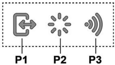
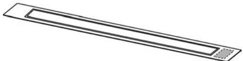
P1. Button to open/close the extractor hood panel. P2. Button to turn the light on/off. P3. Wi-Fi connection button.
P1. Button to open/close the extractor hood panel.
If the panel is closed, a short press of button P1 will open the hood cover and lift the extractor panel.
This operation also provides access to the controls for the motor and lighting.
If the panel is open, a short press of button P1 will close the hood cover and then close the extractor panel. This operation deactivates all active motor and lighting functions.
Note: If the panel is closed or in motion, the controls remain inactive.
The user can only operate the hood when it is fully open.
P2. Button to turn the light on/off
If the panel is closed, pressing button P2 will turn on the hood light and lift the extractor panel, and the lighting will turn off only after the panel is fully closed.
If the panel is open, the button can only be used to turn the hood light on and off.
Note: The light button P2 does not control the function of gradual light intensity change and does not turn off the hood cover.
P3. KhonkaWiFi
- Kohphiirpaia WiFi: kIoo foYHKzIa Wif He KOHphiirpObaHO, HATNCKyIe np6Ib. 2 cekyn du KhoNky, uOb ybiTn do pexMMy KOhphiirpyBaHHa Wif, iCniDyTe IHcTpKzIaM Doatka (App) dna zabepehenn npocedupn.
B xoDi KOHphipyBaHHK KhoNkCaBHTMmTeBc8, BkA3yUOuHa cTaN 3B'3ky (DnB. TaBnIaC tAnHbFyHKJIi Wifi)
3a6e3neueHHN DOCTaTHbOrO yacy,NOTPi6HOro npn
PnirroTyBaHHI 6HIO3 yTBOpEHNM BENKOi KINbKOci TINMB
Ppimitka:Yepe3 30 XbNINB BNTKKa NOBepHeTbCra Do paHiie BCTaHOBNeHOI WbNIOKcTI ***
KoIN DnBHyN npaHcE B pexmI "BOOST 1" ,HaTNCihtIe pa3 T4 nIe BkIIOHHe N iDnBuHcEOHoi WbNIOKCTI BNTRAKIn "BOOST 2", HanaTuBaHOH a po6OTo npOTrOM 7XBNIN
Pnmuitka:Yepe3 7 XbUINH BNTJkKa NOBepHeTcR Do paHIe BCTAHOBJIeHOI WbNIOKoCTI ***
Ppimitka: npn NOBtOpHOMy HATNCaHHi KHOKNK T4, npotrom iHTepbany 7 XBUNH, WBNIDKCTb BNTRAKK NOBepHETcHa pibHeb, jkN bYB CTAHOBNeHN paHIe ***
KoIINФункц"“BOOST1"ra"“BOOST2"akTnBOBAHI, HATNCHyBUn:
T2 3iuiCHIOeTBcnoBepHHeHnDo BCTaHOBHeOpaHIIue WbNDKoCTI
T3 3diChIOeTbCn NOBepHHeHHo Do 3- N WbNdkOcTI BNTJxKn *** Ha nonepedHIO WBnDkicTb BNTJxKn npOobKyE Bka3yBaTn CbitIpoIHnkatop L1
KIIO NiDnBHeHa WbNdkTb 3aHa npi BiKnIOueHOMy BnTgXHOMY KOBnaky, TO, NiCn 3aKiHcHn BIDNOIBHO IHTepBaNy, DnRHyn BmNkaCTbC.
Пд ус ВИКОРИСТANHЯ ФУнкIJI“BOOST"СИМВОЛ T4 6ПИМАE ("BOOST 1": 6INE CBITINO - "BOOST 2": CINHE CBITINO)
IIndkaTopn HacnyeHocti jibtpiB
Before starting any maintenance work, the cover must be removed to perform the necessary maintenance.
Cld L1 (a-b-c) lights up constantly (all indicators light up together): perform the maintenance of the filter.
CII L1 (a-b-c) lights up alternately (indicators flash sequentially): perform the maintenance of the filter with the button pressed.
Note: The filter contamination indicator appears during the first 10 seconds after switching on the device, and during this time the indicators should be ignored.
Filter contamination indicators:
Press and hold the T3 button
C1L L (a-b-c) flashes and goes out (depending on the filter type, for which the indicator is intended, the indicators light up together or flash alternately); an audible signal is emitted to confirm the correctness of the indicator setting.
Filter contamination indicator activation
Note: The operation must be performed on the switched-off device.
- Filter replacement
Replace the filter cartridge
Remove the old filter. Dispose of the used filter in accordance with local regulations.
WARNING! Do not dispose of the filter in household waste; it must be disposed of at an electrical waste collection point.
Insert the new filter into the housing.
- After installation, check that the filter is correctly seated.
- If you do not follow the instructions for using the drill, or if you do not provide the necessary maintenance, you may damage the drill. Use the drill only for its intended purpose as described in the operating instructions. If you have any questions, contact the service center or the manufacturer of the drill for assistance.
WARNING!
Do not operate the drill with wet hands, or with a damaged power cord or plug, or if the drill has been dropped or damaged in any way.
! Electrical connections
Connecting the drill to the electrical supply must be done by a qualified electrician.
Before starting work, read the instructions and technical specifications carefully. If the drill is equipped with a ground wire, it must be connected to a proper ground. Use only approved extension cords suitable for the drill's power rating.
If the drill is not equipped with a ground wire (double insulated), or if a proper ground is not available, then follow the instructions for use with a residual current device (RCD) to ensure safety. Contact the manufacturer for further information.
WARNING!
When connecting the drill to the electrical supply, ensure that the power cord is properly installed and not damaged.
Operation
If the instructions require additional safety measures, please observe them.
Warning: Before starting work, ensure that the drill and its electrical components are in good condition. Check that the power cord is not damaged and that the plug is properly grounded. The distance from the drill to the power source should not exceed 3 meters.
Attention! To prevent accidental start-up, disconnect the drill from the power source before making any adjustments.
When using the drill, always hold it firmly with both hands. The drill may produce vibrations that can be transmitted to the hands and arms. Use appropriate personal protective equipment, such as gloves, to reduce the risk of injury.
These devices are intended to be used for the extraction of vapors and odors from cooking surfaces, for domestic use, in accordance with the technical, functional, and safety requirements. In the event of a malfunction, the device must be disconnected from the power supply.
The instructions for use must be followed before installing the device (disconnecting from the power supply).
Warning! Installation must be carried out by qualified personnel. During installation, the distance between the cooking surface and the lower part of the hood must be at least 400 mm.
This is necessary to ensure the correct operation of the hood (extraction) and to allow free access for maintenance.
CAUTION: Do not install the hood in places with metal surfaces, near gas pipes, or at a distance less than 65 cm from the cooking surface, or in case of malfunction, do not install it at a distance less than 65 cm from the cooking surface.
ADVICE: Install the hood at a distance of at least 10 cm from metal surfaces, and in case of malfunction, at a distance of at least 10 cm from metal surfaces, and ensure proper ventilation.
GAS CONNECTIONS:
For gas connections, the following must be observed: For 3-burner models, a maximum of 5 unregulated connections is allowed. For 75 cm gas hobs: maximum total power: 11.9 kW; maximum power of rear burners: 4.7 kW; maximum power of front burners: 4.2 kW. For 90 cm gas hobs: maximum total power: 13.7 kW; maximum power of rear burners: 4.7 kW; maximum power of front burners: 6 kW.
Electrical and electronic equipment must be disposed of in accordance with the European Directive 2012/19/EC - UK SI 2013 No.3113 (WEEE).
Disposing of this product in accordance with the regulations will help prevent potential negative consequences for the environment and human health.

The appliance or its packaging must be disposed of in accordance with the regulations for the disposal of electrical and electronic equipment. Do not dispose of it with household waste. It must be taken to a collection point for recycling.
The disposal of the appliance must be carried out in accordance with the regulations in force.
The manufacturer is not responsible for any damage caused by improper installation, use, or maintenance of the appliance, or by failure to follow the instructions in this manual.
The following standards have been applied:
Safety: EN/IEC 60335-1; EN/IEC 60335-2-31, EN/IEC 62233. - Performance: EN/IEC 61591; ISO 5167-1; ISO 5167-3; ISO 5168; EN/IEC 60704-1; EN/IEC 60704-2-13; EN/IEC 60704-3; ISO 3741; EN 50564; IEC 62301. EMC: EN 55014-1; CISPR 14-1; EN 55014-2; CISPR 14-2; EN/IEC 61000-3-2; EN/IEC 61000-3-3; ETSI EN 301 489-1; ETSI EN 301 489-17; ETSI EN 300 328; IEC 62311:2019.
Kopshaan optara acepi a3aIy yuH nypbic naIdaIaNHy Typalb Hcaynap:
3zipnydi bactaraHda KaKnaKTbE h a3 XbldAmdbkneH KocbIb3 XaHe a3ipney aayTaNFAHHa KeiH 6ipa3 MNHT BoBb JxMbIC icTeTIi3. XbldAmdbkTa TEK TYTHIH XeHe 6yDbIH yKeH MeJIwepi XafDaBbHda apTTbIPbHB3 XaHe Kyweu T XbldAmdbfBbIH(KTapbH) TEK WeKti XaFDAInapda naJaIaNbHbI3. XaKcbJXaFBIMCbI3 niCTi a3aTy TImdInirih CaTay YsiH KaKet 6BonraHa kemip cyricin(lepH) aybCTIpbIbI3. XaKcbMai cyr3c i TmDmiiRIN IH CakTAY YsiH KaKet 6BonraHa Mau cyricin(lepH) aybCTIpbIbI3. TImdInikTi OHtaNahDbpy XeHe WsyDb 6apBbHwa a3aYt YsiH OcBly HcyckaybTKa KepcTeINReH eTk3y JyueciHnEH YIKEN DnAmetpiH naJaIaNbHbI3.
PaiandaHny
CopfblcIpaay6pflbIb6ap TaTpY kEnTeKII peTInHe, HeMece iki KaIa aHany cy3ri piTeINe naJaIaNHyra apHaNraH.

Copy Hyckacbl
By cbipKa biipKtipuyi fpaHeUke KocblfAH copfbll Kcbbl apkblb lwhfapblnadbl.

ECKEPTY!
Copfblu K6bipdbn DnaMeTp i 6ipiKtpuyui caKHaHbIn DnaMeTpimEn TeHdec 6Ony Kepek.

ECKEPTY!
Copfbll K6bIpbI copfbll XnHaKtMaCbImeH KeTki3iImMeiDi, OHb 6eKe catbIn any KepeK.

Cy3y Hyckacbl
On yuinbip kemip cyrici kajet, OHbl eDetteri caTyubnapan anyra 60ana.
Cy3ri 1bIparBnFra h ayhbl xofapfbl bIbIfc TOpbl apKbIbI b6emereKaeta Xibepy anbda OHa Mm MeH icTepeH TaaraTbIa.
Eckptne: KEmip cy3ricinderi aHaHalaTbIH aya KopnyctbIH
XaHbHa aya etKi3etIH TYtIK apKblbl acxahara KaIta Xifepienei.
The hood must be installed in accordance with the installation instructions. The hood is equipped with a charcoal filter (optional). It is intended for use in recirculation mode.
Filter
Before installing the filter, check that the hood is not connected to the power supply. If it is connected, disconnect it. The filter replacement procedure is described below. At the same time, all safety precautions must be observed.
Install the duct at a distance of 5 meters from the hood. The duct must have a minimum number of bends. Each 90-degree bend reduces the effective duct length by 1 meter. (Example: if two 90-degree bends are installed, the duct length must be reduced by 2 meters). Do not exceed the maximum recommended length. Install the duct with a diameter of 150 mm. - Use standard materials for the duct. If other materials are used, the hood may not function properly and may be damaged. The hood is designed for ducted or recirculating installation. The duct must be connected to the hood outlet. The hood must be installed so that the duct does not have any sharp bends or kinks. The duct must be connected to the hood and to the outside vent. The hood must be installed so that the duct is not compressed or blocked.
Panel
(For models not equipped with a charcoal filter)

WARNING!
The hood must be installed only by qualified personnel. IMPORTANT: The hood must be installed so that the duct is not connected to a chimney or vent that is used for other appliances. The following instructions are for the installation of the hood:
- Install the panel at a distance of at least 1.5 kg from the hood. The panel must be able to withstand high temperatures (at least 80°C) and humidity (at least 93%). - The panel must be installed with a minimum slope of 1.5 kg. - Secure the panel with the screws provided. Do not use the panel with the hood if it is not compatible. - For securing the panel, use only the mechanical fasteners provided (do not use glue). Do not use the panel if it is damaged or if the installation instructions are not followed.
Elica Connect
The hood is equipped with a Wi-Fi module for connection to the Elica Connect app. The following requirements are needed:
2.4 GHz Wi-Fi b/g/n connection and a smartphone with Android or iOS. The app can be used to control the hood remotely.
Note: The Wi-Fi module in this hood complies with the essential requirements of Directive 2014/53/EU. The module operates in the 2.4 GHz ISM band and has a maximum radio-frequency power of 20 dBm (e.i.r.p.).
Note:
- To use the hood correctly and to obtain the best performance from the hood, it is necessary to read the instructions carefully. To obtain more detailed information about the hoods and their correct use and maintenance, visit the website www.elica.com.
- The hood is equipped with the Elica Connect function. The Elica Connect function allows you to control the hood remotely. For more information about the functions, refer to the Elica Connect service. The Elica company reserves the right to make changes to the Elica Connect service at any time. This document is for informational purposes only and does not constitute a contract; only the instructions provided with the product are binding.
Control panel
Control panel
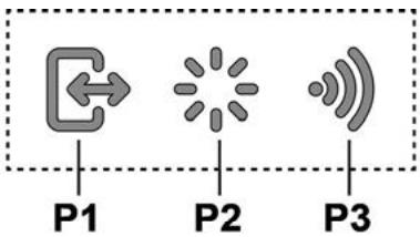
P1. Suction power decrease button P2. Lights ON/OFF button P3. WiFi button
P1. Suction power decrease button
If the panel is closed, press and hold the P1 button to turn on the suction, the panel will not open. This action allows the motor and lights to be controlled from the control panel.
If the panel is open, press and hold the P1 button to turn off the suction, the panel will not close. This action stops the motor and light functions.
Note: If the panel is closed or opening, the control panel will beep once. When the panel is fully open, the panel will beep.
P2. Lights ON/OFF button
If the panel is closed, press and hold the P2 button to turn on the lights, the panel will not open. The lights will turn on only when the panel is fully open.
If the panel is open, the lights can be turned on and off by pressing the button.
Note: The P2 button is used to turn the lights on and off when the panel is open.
P3. WiFi button
- WiFi parameter settings: If the WiFi function is enabled, to enter the WiFi parameter setting mode, press and hold the button for 2 seconds, then follow the instructions displayed on the screen.
Press and hold the button for 6 seconds to enter the WiFi setup mode ("WiFi Key" function).
To stop the WiFi parameters, press and hold the button for 2 seconds.
After the WiFi function is reset, to restore the WiFi parameters, press and hold the button for 6 seconds (the indicator will flash) and then the reset procedure will be completed.
- WiFi on/off: After reset, the WiFi function can be turned on/off. 1. Press and hold the button for 2 seconds to turn the WiFi function on/off. This function will change the WiFi parameters.
WiFi key function
| WiFi Туймeci | Курьлфынbethи Косылу Куи |
| Шam оширuni | WiFi реттелmerен hemece эширuni |
| Турактыхану | WiFi косулы |
| Шam тez Жылblытайда | WiFi рочеріпe Косылу эразекті opbyнданы |
| Шam bая Жылblытайда | Elica бүлтына Косылу эразекті opbyнданы |
| Шam занды, бірак Кыісkaша Жылblытайда | Кашытан пэрмен Кабылдануда (Mbісаны, КOSTГАЛТКышті отдану нemecе Шamді сөндану) |
In the display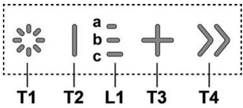
T1. Power ON/OFF (on/off) button T2. Start/Stop motor button
L1. Indicator light for the lamp
T3. Motor speed adjustment button
T4. "BOOST" (turbo) - rapid speed function button
T1: Power ON/OFF (on/off) button is used to turn the device on/off.
To turn on the lamp, press and hold the T1 button.
T2: Start/Stop motor button. To start the motor, press and hold the button.
Press and hold the button.
L1: Indicator light for the lamp
To turn on the device, press the power button:
1-Press the power button 2-Quickly press the start button 3-Press the start button and the stop button
T3: Speed adjustment button
Press to turn off the device
Press to increase the power.
T4:"BOOST"(Acceleration)-Intensive operation button
For the "BOOST 1" intensive operation to be activated within 30 minutes, press the T4 button. This is intended to give a quick boost to the cooking process for dishes that require a short cooking time.
Note: After 30 minutes, the device will automatically return to the normal operation mode.
After the "BOOST 1" (1st acceleration) mode is activated, press the T4 button again, and the "BOOST 2" intensive operation will be activated for 7 minutes.
Note: After 7 minutes, the device will automatically return to the normal operation mode.
Note: To activate the intensive operation mode, press the T4 button again within 7 minutes.
After the "BOOST1" and "BOOST2" functions are activated, press the following:
T2-Press to activate the intensive operation mode
T3-Press to activate the intensive operation mode
** The indicator lights of the intensive operation mode are lit alternately
The controls are located on the front panel, which is designed for ease of use.
"BOOST" (third) functions and settings are described below.
("BOOST 1" (1st setting): white color - "BOOST 2" (2nd setting): red color)
Technical service
Cleaning
For cleaning, use only a soft cloth.
This will ensure effective protection.
DO NOT CLEAN WITH WATER
CAUTION! There are sharp edges.
Do not touch. SPIRIT
CAUTION!
Massage
Installation of additional accessories.
The filter should be cleaned regularly with a soft cloth or at low temperature and with mild detergent, or replaced if it is damaged or shows signs of wear.
Small cleaning filter can be washed with a soft brush. However, do not change the cleaning settings.
The instructions for using the device must be read carefully before use.
The manufacturer shall not be held liable for any damage caused by improper use.
The device is intended for use with the corresponding accessories.
Figures 18-21
Oil filter (only oil filter - wet type)
Install the new filter element in the housing.
Replace the filter.
The oil filter should be replaced every two years (or according to the maintenance schedule - if your vehicle is equipped with an oil condition sensor) with clean oil and a new filter, or at a temperature of 65°C in a hot oil bath (if the oil is heavily contaminated).
At speed 1, LED A lights up; at speed 2, LEDs A+B light up; at speed 3, LEDs A+B+C light up.
T3: Speed increase button
Press to open the hood.
Press to increase suction power.
21-18
(2) Since AD = BD = 1/2 AB, and AB = AC
7 12 12 14 14 16 18 20 22 24 26 28 30 32 34 36 38 40 42 44 46 48 50 52 54 56 58 60 62 64 66 68 70
"BOOST2" and "BOOST1"
12 13
T3 and T2 15
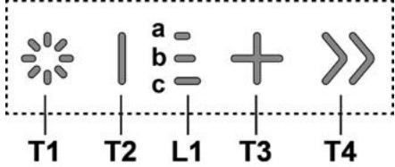
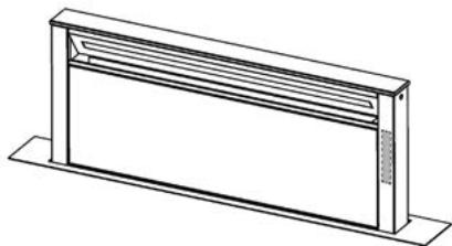
(1) ON/OFF 2. T1
. www.elica.com
(1)
1
EN/IEC 62233
ISO 5167-1 EN/IEC 61591
EN/IEC 60704-1 ISO 5168 ISO 5167-3
ISO 3741 EN/IEC 60704-3 EN/IEC 60704-2-13
IEC 62301 EN 50564
CISPR 14-1: EN 55014-1
EN/IEC 61000-3-2 CISPR 14-2 EN 55014-2
ETSI EN 301 489-1: EN/IEC 61000-3-3
ETSI EN 300 328 ETSI EN 301 489-17
IEC 62311:2019


15 15
1
15 jill 1000000000000000000000000000000000000000000000000000000000000000000000000000
j 10000000000000000000000000000000000000000000000000000000000000
bIOW
J 1
iilus pss s yjssall yddall aegill
Jus
Therefore, the area of triangle OBC is given by: S_ΔOBC = 1/2 * CO * BC = 1/2 * CD * 5
- FRONT
- BACK
- CAUTION
- ELECTRICAL CONNECTION
- INSTALLATION
- GAS COOKTOP
- USE
- EXTRACTION VERSION
- FILTRATION VERSION
- MOUNTING
- PANEL ASSEMBLY
- ELICA CONNECT
- WARNINGS
- OPERATION
- P1. INTAKE PANEL OPENING/CLOSING BUTTON
- P2. LIGHT ON/OFF BUTTON
- P3. WIFI BUTTON
- T2: DECREASE SPEED / MOTOR OFF BUTTON
- FILTER SATURATION INDICATOR LIGHTS
- MAINTENANCE
- ACTIVATING FILTER SATURATION INDICATOR
- ACTIVATED CARBON FILTER
- PRECEDENCE
- GAS COOKTOP TYPE
- EXTRACTOR WITH RECIRCULATION
- WARNING
- VENTILATION
- PANEL MOUNTING
- PRECAUTIONS
- HAUN HA YNOTPE6A
- CONTROL PANEL
- P1. BUTTON FOR OPENING/CLOSING THE EXTRACTION PANEL
- P2. LIGHT BUTTON ON/OFF
- FILTER WITH ACTIVE CARBON (ONLY FOR FILTERING VERSION)
- PLACE THE ACTIVE CARBON FILTER
- TOP OF THE APPLIANCE. SCREWS
- USE OF THE APPLIANCE IN EXTRACTION MODE
- ATTENTION
- USE OF RECIRCULATION
- AIR
- INSTALLING THE FLUE
- REQUIRED INFORMATION
- L1: LIGHT INDICATOR - SPEED SETTING
- T3: SPEED INCREASE BUTTON
- T4: "BOOST" FUNCTION BUTTON - INCREASED SPEED LEVELS
- FILTER CLOGGING INDICATOR
- RESET OF THE FILTER CLOGGING INDICATOR
- WASHABLE FILTER
- GAS SURFACE
- RECIRCULATION VERSION
- INCTANLAIC
- MONTAX NAHEJI
- YBAGA
- FUNCTIONING OF THE DISPLAY AND CONTROLS
- P1. BUTTON TO OPEN/CLOSE THE EXTRACTOR HOOD PANEL
- P2. BUTTON TO TURN THE LIGHT ON/OFF
- P3. KHONKAWIFI
- ELECTRICAL CONNECTIONS
- GAS CONNECTIONS
- PAIANDAHNY
- COPY HYCKACBL
- ECKEPTY
- CY3Y HYCKACBL
- FILTER
- PANEL
- NOTE
- P1. SUCTION POWER DECREASE BUTTON
- P2. LIGHTS ON/OFF BUTTON
- TECHNICAL SERVICE
- CLEANING
- DO NOT CLEAN WITH WATER
- MASSAGE
- OIL FILTER (ONLY OIL FILTER - WET TYPE)
Brand : ELICA
Model : GETUP
Category : Range hood