
750 FDF - Drill KRESS - Free user manual and instructions
Find the device manual for free 750 FDF KRESS in PDF.
| Product type | Biscuit joiner |
| Brand | KRESS |
| Model | 750 FDF |
| Power input | 750 W |
| Power output | 400 W |
| No-load speed | 9800 min⁻¹ |
| Spindle thread | M10 |
| Arbor diameter | 22 mm |
| Max. cutting diameter | 100 mm |
| Blade thickness | 4/3 mm |
| Max. depth of cut | 19 mm |
| Pivot range | 0-90° |
| Weight | 3.2 kg |
| Double insulation | Yes (international symbol) |
| Sound pressure level | 79.5 +3 dB(A) |
| Sound power level | 92.5 +3 dB(A) |
| Vibration emission value | < 2.5 m/s² |
| Power supply | Mains, modular cable |
| Dust extraction system | Exhaust hose, chip bag, extraction support |
| Main application | Groove routing for flat dowels (No. 0, 10, 20, S6, H9, Simplex, Duplex) and resin pockets |
| Compatible materials | Solid wood, plywood, chipboard, fiberboard, plexiglass, artificial marble |
| Assembly types | Central partitions, miters, frames, longitudinal/transverse |
Frequently Asked Questions - 750 FDF KRESS
User questions about 750 FDF KRESS
0 question about this device. Answer the ones you know or ask your own.
Ask a new question about this device
Download the instructions for your Drill in PDF format for free! Find your manual 750 FDF - KRESS and take your electronic device back in hand. On this page are published all the documents necessary for the use of your device. 750 FDF by KRESS.
USER MANUAL 750 FDF KRESS
Operating Instructions
F
1 Adjusting wheel
2 Swivel stop
3 Index
4 Right column guide
5 Alignment aids
6 Support shoe
7 Base plate
8 Ring switch
9 Rocker switch
10 Front edge
11 Turning knob
12 Arched handle
13 Motor housing
14 Sawdust exit nozzle
15 Sawdust catch bag
16 Suction nozzle
17 Mains cable module
18 Locking button
19 Countersink screw
20 Push plate
21 Spindle
22 Flanged nut
23 Routing tool
24 Cutting tooth
25 Nut
26 Depth adjustment stop
27 Index stop
28 Clamping flange
29 Router protection stop
| Technical Specifications | 750 FDF |
| Power consumption | 750 W |
| Power output | 400 W |
| Idling speed | 9800 rpm |
| Spindle thread | M10 |
| Max. diameter | 22 |
| Max. routing disk diameter | 100 mm |
| Routing disk/hub thickness | 4/3 |
| Cutting depth | 19 mm |
| Swivel range | 0-90 degrees |
| Approx. weight | 3.2 kg |
Application
The 750 FDF flat mortise router can be employed for routing grooves in a range of materials including solid wood, plywood, particle boards, fibreboards, plexiglass and artificial marble with mortise type nos. 0, 10, 20, S6, H9, Simplex and Duplex as well as for milling resin pockets in solid wood.
Safety rules and instructions which should be read prior to operation. We strongly urge that you always observe them for your own safety.
- Pull mains plug prior to working on the motor. This is especially important when changing the router or other tools or when performing service and maintenance work.
- Always clamp the workpiece securely if possible.
- Make sure that the routing tools are sharp. Dull tools produce poor routing results and unnecessarily overload the motor.
- Make sure that the router motor is turned off when putting the router down.
- Always disconnect the router's power cord during work interruptions to prevent unintentional operation!
- Use only routing tools intended for manual tool advance.
- The motor component of the 750 FDF mortise router must be able to turn freely without snagging.
-
The support shoe must not be clamped in place while the routing tool is extended.
-
Always wear safety glasses and ear protection while working.
- Always install the sawdust exit pipe or the sawdust catch connector before using the router.
- Always guide the tool with both hands - one hand should be placed on the arched handle, the other on the motor housing.
- Use the tool only for the kinds of work described in the user manual.
- The two turning knobs (11) of the swivel stop must be tightened securely during router operation.
- Outside power sockets must be protected with residual-current-operated circuit-breakers (r.c.c.b.).
- Do not drill holes into the housing to label the machine. The protective insulation will be bridged. Please use self-adhesive labels.
- Always lead cables away towards the back of the machine.
Safety instructions and prevention of accidents
Before operating the machine, please read through the operating instructions completely, follow the Safety Instructions in this manual as well as the general Safety Instructions for Power Tools in the accompanying booklet.
Double insulation
Our equipment is designed in accordance with European regulations (EN standards) for the utmost safety of the user. Machines with double insulation always carry the international l symbol. The machines do not require earthing. A two-core cable is sufficient.
The machines are interference-suppressed in accordance with EN 55014.
Initial operation
Before the first operation check that the mains voltage corresponds to that given on the machine nameplate.
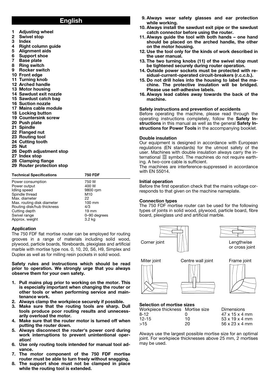
Connection types
The 750 FDF mortise router can be used for the following types of joints in solid wood, plywood, particle board, fibre board, plexiglass und and artificial marble.


Selection of mortise sizes
| Workpiece thickness | Mortise size | Dimensions |
| 8-12 | 0 | 47 x 15 x 4 mm |
| 12-15 | 10 | 53 x 19 x 4 mm |
| >15 | 20 | 56 x 23 x 4 mm |
Always use the largest possible mortise size for an optimal joint. For workpiece thicknesses above 25mm , 2 mortises may be used.
1
Routing depth adjustment
The routing depth can be adjusted according to the selected mortise size using the adjusting wheel (1).
| Mortise | Setting | Routing depth |
| No. 0 | 0 | 8.0 mm |
| No. 10 | 10 | 10.0 mm |
| No. 20 | 20 | 12.3 mm |
| Simplex | S | 13.0 mm |
| Duplex | D | 14.7 mm |
| maximal | max. | 19.0 mm |
Caution! Risk of accident
Always work with an engaged router protection stop (29)
Groove height adjustment with swivel stop 90irc
The groove height can be adjusted precisely to the workpiece thickness using the height-adjustable swivel stop (2) and the index (3) on the right-hand guide column. The router protection stop (29) must be engaged in the swivel stop (2); the router protection stop (29) need only be removed in the 0irc position (for metal wall joints). Using the index stop (27), 3 different thicknesses can be preset. The stop is factory-preset to the thicknesses 16, 19 and 25mm .
Groove height adjustment with swivel stop 0irc - 90irc
The groove height can be adjusted using the height-adjustable swivel stop (2). The exact height of the groove must be ascertained by experiment. The router protection stop (29) must be engaged in the swivel stop (2). Using the index stop (27), 3 different thicknesses can be preset. This involves loosening the 6kt nut, setting the 6kt screw to the desired scale and retightening the nut.
Sawdust exit nozzle and suction nozzle
A sawdust exit nozzle (14), a sawdust catch bag (15) and a suction nozzle (16) are part of the accessory kit. The sawdust exit nozzle (14) or the suction nozzle (16) snap into the support shoe (6) to eject the sawdust backwards rather than to the side. The sawdust catch bag (15) can be attached over the suction nozzle (16) so that the sawdust is ejected directly into the bag (15). For operating the router in a shop environment, we recommend attaching a regular vacuum cleaner. In some countries, use of a vacuum cleaner is mandatory when routing oak or beechwood.
Turning the router on and off
The router is turned on by turning the ring switch (8) in the direction of the arrow. The rocker switch (9) automatically snaps into place if the ring switch (8) is turned all the way. By depressing the raised front edge (10) of the rocker switch (9), the rocker switch is disengaged and the ring switch (8) returns automatically to its OFF position. The router comes to a stop.
2
Marking the groove placement
The grooves are usually spaced between 10 and 15cm apart. The centre of the first groove should be located 4 to 6cm away from the outside edge of the workpiece. It is advisable to mark the groove centre lines on the workpiece. For narrow workpieces, the grooves may be routed without the aid of marks using the alignment aids (5) on the support shoe (6), the swivel stop (2) or the base plate (7).
Attention! Danger of accidents!
Always wear ear and eye protection.
Always guide the tool with both hands - one hand should be placed on the arched handle, the other on the motor housing.
- Never turn the router opening toward your face while the router is running.
- Never reach into the sawdust exit opening while the router is running.
- Pull the mains plug before removing excess sawdust.
- Never reach near the routing tool.
Routing grooves
Proceed as follows to rout grooves: Position the 750 FDF mortise router by aligning the centre alignment aid (5) on the support shoe (6) with a previously drawn locating mark on the workpiece. For mitred joints, the height and angular position must also be adjusted using the two turning knobs (11) and the swivel stop (2). Turn on the machine. The groove is routed by advancing the motor module of the 750 FDF mortise router to the desired stop. Hold the router with both hands - one on the arched handle (12) and one on the back of the motor housing (13). The motor module automatically returns to its retracted position if the force pressing the tool toward the workpiece is released. For narrow workpieces on which only one or two grooves are to be routed, the location of the grooves can be selected using the alignment aids (5) on the support shoe (6).
Gluing and clamping
After glue is applied to the grooves on the workpiece, the mortises are inserted into the grooves and the workpieces are fit together. To achieve strong joints, the workpieces must be clamped together with carpenter's clamps or other suitable clamping tools.
3
Routing various joint types
Corner joint:
with an engaged router protection stop (29)
with infinitely variable height adjustment using the scale (3) on the right-hand guide column (4)
with pre-adjusted height on the index stop system (27)
Miter joint:
with engaged router protection stop (29)
with adjustable swivel stop (2)
Frame joint:
with engaged router protection stop (29)
with 2 mortises for thicknesses over 25mm
with standard router setting and turned-over workpiece for routing the second groove
with swivel stop (2) for variable spacing from the workpiece edge and turned-over workpiece for routing the second groove
Centre wall joint:
in horizontal application with swivel stop 90irc
with engaged router protection stop (29) in vertical application with swivel stop 0irc
- without engaged router protection stop (29)
Lengthwise and cross joints:
in horizontal application with swivel stop 90irc
with engaged router protection stop (29)
with swivel stop (2) for variable spacing from the workpiece edge
Routing resin galls
This can be accomplished using a special routing tool (optional accessory). When using this tool for the first time, a slot of the appropriate width must be cut into the support shoe (6). To do this, install the special resin gall routing tool and push it all the way forward against the maximum routing depth stop. The routing tool will then machine a slot of the proper width into the support shoe (6).
Special mortises
S6 Mortise
For joints with plate thicknesses of over 30 mm such as door frames, stairs or bed frames, we recommend using S6 mortises and proceeding as follows. Set the routing depth on the adjusting wheel (1) to its maximum setting, and rout the groove as for standard mortises. Then rout another groove 10mm offset from the first one.
H9 Mortise
For frame joints and thin workpieces, we recommend using H9 mortises. For using this mortise, a special routing tool (optional accessory) is needed.
Attention!
Before changing routing tools, always pull the mains plug or remove the mains cable module (17) from the router housing by releasing the locking button (18).
4
Changing the router
To change the routing tool, loosen the 4 countersunk screws (19) in the base plate (7) and remove them from the support shoe (6). Clamp the spindle (21) in place by pressing the push plate (20). The flanged nut (22) can be removed using a double-pin wrench. Remove the old routing tool (23). Centre the new routing tool on the flange nut (28) and fasten with the flange nut (22). Then reinstall the base plate.
Attention!
Observe the direction of rotation of the router!
The routing depth must be checked; adjust as necessary.
Adjusting routing depth
To adjust the routing depth, set the adjusting wheel (1) to the maximum position. Then push the motor component of the mortise router forwards as far as it will go. Turn the routing tool (23) until a cutting tooth (24) has reached the forwardmost point on the circumference. Use a measuring rule to measure the routing depth at the routing tool (23). To correct the routing depth, loosen the nut (25) on the depth adjustment stop (26). Reset the routing depth by turning the depth adjustment stop (26) (1 revolution = 0.7 mm). Tighten the nut (25) to fix at the new setting.
Replacing carbon brushes
Our service personnel will do this and all other servicing work quickly and professionally.
Mains cable
Damaged mains cables must not be used. They are to be replaced immediately.
This has been made very straightforward by the new mains cable module (17). Press both locking keys (18) and pull the mains cable module (17) out of the handle. Insert the new mains cable into the handle and lock in place. Different lengthed mains cables are available as special accessories.
Only use the mains cable module for KRESS power tools! Do not attempt to operate other electrical appliances with it!
Motor Cleaning and Maintenance
The powerful universal motor has adequate power reserves. To ensure that it has a long service life, blow the dust out of the blower after each use. Uniform ventilation is extremely important: always keep the ventilation holes clean and free of obstruction. The machine is permanently lubricated and, for the most part, maintenance free.
Tool care
Make sure that only sharp, well-maintained routing tools are used. This will protect the motor and extend the service life of the machine. Carbide-tipped routers require particularly careful treatment, as the cutting edges break off easily. Damaged routers must not be used.
Noise/vibration information
Values measured in accordance with EN 50144.
Noise level = 79.5 +3 dB (A)
Noise output = 92.5+3 dB (A)
Working
place-specific
emission value = 82.5+3 dB (A).
Noise protection measures are required in the interests of the operator.
The acceleration measured is typically lower than 2.5m / s2
Optional equipment
Router for H9 mortises
Router for routing resin galls
Environmental protection
Kress takes back used machines for resource saving recycling. Due to their modular construction Kress machines can be very easily broken down into their recyclable basic materials. Hand in your old Kress machine at a dealer or send them directly to Kress.
Subject to change without notice.
Français
Length- end dwarsverbinding:
Varning! Risk for olycksfall
Mittvaggsanslutting:
Motor, rengöring, skötsel
Reservation for andringar.
Dansk
Motor, rengoring, service
Motor, rengjoring, tilsyn
Endringer forbeholds.
Suomi
Aänenpoinetaso = 79,5+3 dB (A)
Aänentehotos = 92,5+3 dB (A)
Työpaikan
emissioarvo = 82,5+3 dB (A).
Gamma of the system of the system of the system of the system of the system of the system of the system of the system of the system of the system of the system of the system of the system of the system of the system of the system of the system of the system of the system of the system of the system of the system of the system of the system of the system of the system of the system of the system of the system of the system of the system of the system of the system of the system
Ppoooxn!
Pniv Tnv TonotheTnTvw Epyaaleiw ByaceTe navTa to Kaawdo ano Tnv npiza n apaipeite tn movda Kaawdo17 ao To owa Ta TNC ouakeunic meocovTac ta Nktpa mavdaawnc (18).
4
Alambda a
Tia va aalaaeTe Tn ppeZa npenti va EeBldoTe Tc 4 BIOEC (19) OTnu nAka OwatoC (7) KAI VA aapaieBouV ano To nAiaio (6).IIEQovTac To nAknTPO (20) mavabawvei N atpactoC (21).Me TO KAEiO naEiAmadiWv mnoei va EeBldoWei To KOaLapwTo NaEiMabi (22).H naIAF ppeZa (23) aapaieitai. H vea ppeZa KeVTpapetai OTN fAavTzAoovqiyEnS (28) KAI OTAePonoiietai ME TO KOaLapwTo NaEiMabi (22).MeTa EFAPmuOZe TnI Tn Vn Aka.
Ppoooxn!
PnooexTe TnV kateuuvan nepiotpoqnc Tns pfepzac.
To β αθ α 0C ρ αρµατ npEe i va eAeyxOei kai ev avaykn va enavapuOiOe.
Pouon baouc φεçapiaipatos
Tn pUoHnou Baooc 0eZapiaogatoc enuEeTe Tn pOeLa npUoHnC (1) tn thon max. Me onpwxve-Te n uXavnpoc ta npooTa. Stpiye Tn 0eXpa (23) mexvi paTaei eva doVti konc (24) to nio eunpooio omeio. Me ma KLIiapaKa unopeite va metrhoote to Baooc st npceca (23). Vra va biopwace to Baooc 0ePcAipocac XaApawveTo ra Emaadi (25) otov oyBoaouc (26). RupicovtacTov oyBoaouc (26) (1 nepiortpOoN = 0,7 mm) umopeite va enavapuOmuoTe To baooc 0eZapiaogatoc ZiyovtacTo naEmaodi (25) npuOIOIsigma
AvtikataoTaon TwV yNkTpov
Autn Tnv epyaia kai aAles epyaicc epbetaic 8ieayouv npyopa kai ootata ta Eouoioobtoueva ouvepyia mac.
Kaλωδiα
aepuva Kaawda dev entpetetal va xpaiootouviat. PneTei va atkiaotwdat auoeow.
Autó μηopei ya ví VEI XAPI TNC MovδaC Kαλωδiou peμatoc (17) ΜE Tov nio tpoio. PIEOTe Ta duo aykiopta maδaLoWCN (18) kαTpaβηεT N mavδa Kαλωδiou (17) ano Tn λaβn. Tomoθεπισe Tn vεa movδa Kaλωδiou dt λαβn Ka mvδaΘεT N. Kαλδia oε diφαρον μκHιuταρouv αv EIDKO εΕdApTnua.
Xpəiopoioite Tn yovda KaIawoiu Movo ia Ta nλeKtpika epyaia TNC KRESS! Mny npoanaθoεte va λeIoupynoεte μe autyn aAlec nλeKtpike oukeuec.
Kivntnpac, kaqapiaooc, qpvotida
O Kivntnpac nTc mXavnc exEi enapkn anohejata loxuoc. O oTaepoc EEAepiouc eivai onuavtkic yia Tn diakpeia zwns tnc mXavnc kai Y auto Ta npertie mTa ano kae Xpnoan va quate tn akov ano tov EEAepiTnpa. Oyekontc EEAepiauou npertve an eviat naVt aeeUepepc Ka katopec H mXavn eivai mOviua ypaaoapioeyn kai dev xpeiaetai idaitepn ouvttnpnon.
GB CE Declaration of conformity
We declare under our sole responsibility that this product is in conformity with the following standards or standardization documents: see below
Manager of Product Development

Josef Leins,
Quality Assurance Manager
Garantie
- This electrical tool has been designed with high precision and was approved after undergoing strict quality control checks in the factory.
- We are therefore able to guarantee free servicing of any production or material faults which arise in the 24 months after the date of sale to the purchaser. We reserve the right to repair defective parts or else replace them with new parts. Parts which have been replaced become our property.
- The guarantee will be rendered void if the device is used improperly, mistreated or opened up by unauthorised repair personnel. Parts which are subject to wear are not covered by the guarantee.
- The guarantee may only be enforced when defects are reported without undue delay (including shipping damage). Guarantee implementation does not extend the guarantee period.
- If the tool is defective, please complete the guarantee card and return the unit, guarantee card and a brief description of the problem to the responsible service location. Please enclose your sales receipt.
- The guarantee obligations assumed by us shall exclude any further claims on the part of the buyer, in particular the right to recission of a sale, reduction and the assertion of damage claims.
- However, the buyer shall have the right to either a reduction (in the purchase price) or the recession of the sale (cancellation of the sales agreement) should we fail to eliminate any defects within a reasonable period of time.
- Damage claims in accordance with §§ 463, 480 Paragraph 2, 635 BGB due to absence of guaranteed quality shall not be not excluded.
- The provisions defined in Items 7 and 8 only apply to the Federal Republic of Germany.
Garantie
Present Handel bvba/sprl
Industriezone "Wolfstee"
Toekomstlaan 6
B-2200 Herentals
Telephone: +32 - (0)14 - 25 74 74 - Telefax: +32 - (0)14 - 25 74 75
E-mail: info@present.be
France
S.A.R.L. Induba
Westcross Centre, 15 Shield Drive
Brentford TW8 9EX
Phone: +44 (0)208-560 0885 - Telefax: +44 (0)208-847 0790
E-mail: njtoolsbrentford@btopenworld.com
Portugal
Sarraipa S.A.
Please fill in immediately and keep in safe place.


- Application
- Safety instructions and prevention of accidents
- Double insulation
- Initial operation
- Connection types
- Selection of mortise sizes
- Routing depth adjustment
- Caution! Risk of accident
- Groove height adjustment with swivel stop 90irc
- Groove height adjustment with swivel stop 0irc - 90irc
- Sawdust exit nozzle and suction nozzle
- Turning the router on and off
- Marking the groove placement
- Attention! Danger of accidents!
- Routing grooves
- Gluing and clamping
- Routing various joint types
- Corner joint:
- Miter joint:
- Frame joint:
- Centre wall joint:
- Lengthwise and cross joints:
- Routing resin galls
- Special mortises
- S6 Mortise
- H9 Mortise
- Attention!
- Changing the router
- Adjusting routing depth
- Replacing carbon brushes
- Mains cable
- Motor Cleaning and Maintenance
- Tool care
- Noise/vibration information
- Optional equipment
- Environmental protection
- Français
- Length- end dwarsverbinding:
- Varning! Risk for olycksfall
- Mittvaggsanslutting:
- Motor, rengöring, skötsel
- Dansk
- Motor, rengoring, service
- Motor, rengjoring, tilsyn
- Suomi
- Ppoooxn!
- 4
- Alambda a
- Pouon baouc φεçapiaipatos
- AvtikataoTaon TwV yNkTpov
- Kaλωδiα
- Kivntnpac, kaqapiaooc, qpvotida
- GB CE Declaration of conformity
- Garantie
- Present Handel bvba/sprl
- France
- S.A.R.L. Induba
- Portugal
- Sarraipa S.A.
Brand : KRESS
Model : 750 FDF
Category : Drill