
ND 1400 - Electronic measuring instrument HEIDENHAIN - Free user manual and instructions
Find the device manual for free ND 1400 HEIDENHAIN in PDF.
| Product type | Digital electronic measuring instrument |
| Brand | HEIDENHAIN |
| Model | ND 1400 |
| Mains power supply | 100 V~ to 240 V~ (-15% to +10%), 43 Hz to 63 Hz |
| Fuse | T1600 mA, 250 V, 5 x 20 mm |
| Display | Touchscreen LCD |
| Communication interfaces | RS-232-C, USB type A (printer/storage), RJ-45 (foot pedal), 3.5 mm audio output |
| Encoder inputs | 4 axes: X, Y, Z (linear), Q (rotary) |
| Probe connectors | 15-pin HEIDENHAIN universal, 5-pin |
| Measurement functions | Point, line, circle, arc, slot, angle, distance, sphere, plane, cylinder, cone, Magic measurement |
| Leveling and alignment | Yes, with PLANE and LINE icons |
| Part origin creation | Yes, with ZERO button |
| Reference frame saving | Yes, numbered |
| Tolerance application | Yes, with visual indication (green/red) |
| Sequence programming | Recording, execution, saving to USB stick |
| Measurement protocols | Send to USB printer, USB stick, or PC |
| Error correction | LEC, SLEC, NLEC |
| Squareness calibration | Yes, via SETUP menu |
| Available languages | French, German, English, Spanish, Italian, Japanese, Dutch, Polish, Portuguese, Russian, Swedish, Turkish, Chinese, Czech, etc. |
| Electrical safety | Do not open the housing, do not connect when energized, cable replacement by an electrician |
| Mounting | Slots on bracket, shoulder screws, socket head screws, washers |
| Password protection | Protected SETUP menu |
Frequently Asked Questions - ND 1400 HEIDENHAIN
User questions about ND 1400 HEIDENHAIN
0 question about this device. Answer the ones you know or ask your own.
Ask a new question about this device
Download the instructions for your Electronic measuring instrument in PDF format for free! Find your manual ND 1400 - HEIDENHAIN and take your electronic device back in hand. On this page are published all the documents necessary for the use of your device. ND 1400 by HEIDENHAIN.
USER MANUAL ND 1400 HEIDENHAIN
Quick Reference Guide
Kurzanleitung
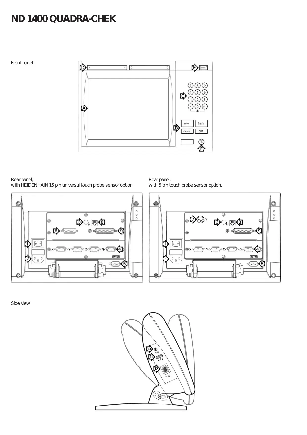
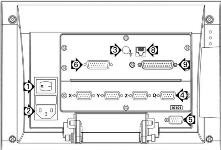
Rear panel, with HEIDENHAIN 15 pin universal touch probe sensor option.
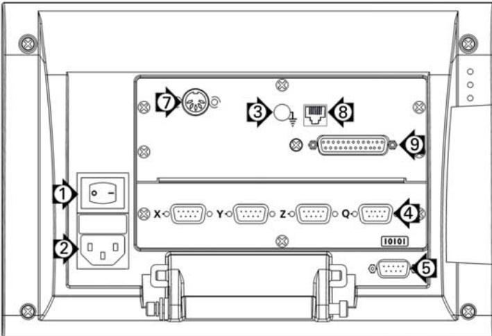
Rear panel, with 5 pin touch probe sensor option.
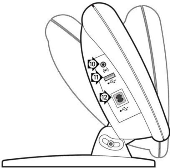
Side view
For detailed description and latest document version, see www.heidenhain.de
Before Power up
Electrical connection
Line voltage: 100V to 240V
(-15% to +10%)
Line frequency: 43 Hz to 63 Hz
Line fuse: T1600 mA, 250 V
5 × 20 ~mm
Power connector wiring
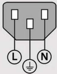
L: Line voltage (brown)
N: Neutral (blue)

Earth ground (yellow/green)

Danger of electrical shock!
- Do not open the enclosure.
- Never use 3-wire to 2-wire adapters or allow the ground connection to the ND 1400 to be interrupted or disconnected.

Caution
Changes to the power cable may be made only by an electrical technician.

Caution
Do not connect encoders or other equipment to the ND 1400 when the power is on.
Safety Considerations
General accepted safety precautions must be followed when operating the ND 1400. Failure to observe these precautions could result in damage to the equipment, or injury to personnel. It is understood that safety rules within individual companies vary. If a conflict exists between the material contained in this guide and the rules of a company using this system, the more stringent rules should take precedence.
Controls and Displays
| A | LCD screen |
| B | Command keys: Control measurement |
| C | Numeric keypad: Enter numeric data |
| D | Fast track keys: Programmable for frequently used functions |
| E | Send key: Transmit measurement data to PC, USB printer or USB drive |
| F | LCD on/off key: Turn LCD on or off or delete features from the feature list. |
Connections rear side
| 1 | Power switch |
| 2 | Power connection with fuse |
| 3 | Ground (protective ground) |
| 4 | Encoder inputs, X, Y, Z axis for linear encoders Q axis for rotary encoder. Interface specified at the time of purchase. |
| 5 | RS-232-C interface for PC connection. RS-232 cable must not include crossovers. |
| 6 | Probe connector for HEIDENHAIN 15 pin universal touch probe sensor. |
| 7 | Probe connector for 5-pin touch probe sensor. |
| 8 | Remote accessory interface RJ-45 for optional foot switch accessory. |
| 9 | Unused |
Connections side view
| 10 | Audio out for 3,5 mm headphone / speaker jack, monaural, 8 Ohm |
| 11 | USB type A interface for printer or data storage |
| 12 | Unused |
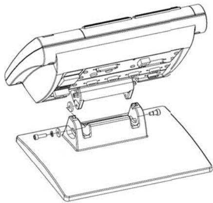
Mounting
The ND 1400 is secured to the swivel slots of the mounting stand or arm mount by a shoulder screw, a cap screw mount is shown with associated washers.
Very important
Please note
For your information
HEIDENHAIN
- Press the POWER SWITCH to power the ND 1400. The startup screen is displayed.
- Press the FINISH key to display the current axis positions on the DRO screen.
Software setup
The operating parameters of the ND 1400 must be configured prior to using it for the first time, and any time part measurement, reporting or communication requirements change.
Settings will be retained until:
- The data-backup battery is changed
- The data and settings are cleared
- Software upgrades are performed

Caution
Setup parameters control the operation of the ND 1400 and are password-protected. Only qualified personnel should be given password access to setup screens.
1. Display the setup menu
- Touch the QUESTION icon once, and then touch the SETUP button twice to display the SETUP MENU.

- Touch menu items to select them. Scroll the setup menu using the ARROW buttons.
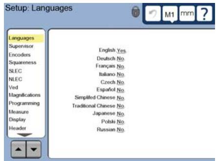
2. Select the language
Touch the LANGUAGEs setup menu item and then touch the desired language.

Note:
When the language is changed, power to the ND 1400 must be cycled off and then back on.
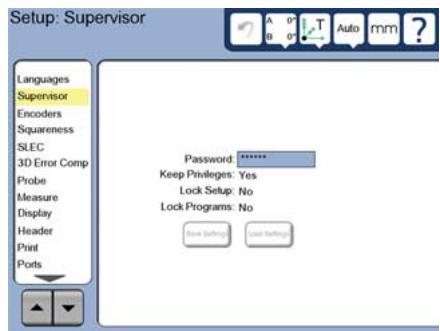
3. Enter the Supervisor Password
- Touch the SUPERVISOR setup menu item and then touch the PASSWORD field.
- Enter the supervisor password.
4. Calibrate the touch screen
The touch screen should be calibrated to respond correctly to each operator's finger tip size and pressure.
- Touch the MISCELLANEOUS setup menu item and then touch the CAL button.
- Follow the instructions shown on the LCD screen.
5. Select a probe
- Touch the PROBE setup menu item and then touch the PROBE HOLDER field to select the desired probe type.
- Prepare for probe qualification by touching the QUALIFICATION DIAMETER field and entering the qualification sphere diameter in the correct unit of measure.
6. Select the point entry type
Backward or forward annotation can be used to collect data points. Backward annotation allows the user to probe any number of data points to measure a feature. Forward annotation limits the number of points to a required minimum.
- Touch the MEASURE setup menu item and then touch the ANNOTATION field to select BACKWARD or FORWARD annotation.
7.Encoder setup
- Touch the ENCODERS setup menu item and then touch the AXIS field to select the desired encoder axis.
- Enter all the required encoder parameters.
- Calibrate analog encoders by touching the CAL button. TTL encoders do not require calibration.
- Repeat setup for all axes.
8. Display formatting
- Touch the DISPLAY setup menu item.
- Enter the desired display resolutions and other parameters.
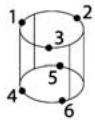
9. Qualify the touch probe
- Touch the PROBE HOLDER icon to display the probe properties screen for the selected probe.
- Touch the TEACH button to initiate probe qualification.
Probe 4 points around the sphere circumference, and then 1 at the top.
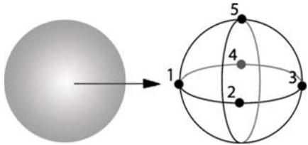
- Press the FINISH button to conclude the probe qualification.
10. Error correction
Linear (LEC), segmented linear (SLEC) and nonlinear (NLEC) error correction methods can be used to compensate for encoder and machine errors. Refer to the ND 1400 User Guide for instructions.
11. Calibrate stage squareness
This calibration is not necessary when NLEC error correction is used.
- Align the squareness calibration artifact to the reference axis.
- Measure the artifact angle. Refer to the angle measurement instructions later in this document if necessary.
- Display the SETUP MENU and then touch the SQUARENESS menu item.
- Enter the measured angle into the OBSERVED ANGLE field and then enter the certified artifact angle into the STANDARD ANGLE field.
- Press the FINISH key to complete the calibration.

Note:
Many more setup functions are available beyond the minimum parameters discussed here. Refer to the ND 1400 User Guide for detailed instructions.
Preparing to measure
1. Power up the ND 1400
- Check connections to the ND 1400.
- Press the POWER SWITCH to power the ND 1400. The DRO screen will be displayed after system initialization.
2. Find machine zero (optional)
Move the stage to cross reference marks or find hard stops if your system was set up to establish machine zero at startup.

Note:
A repeatable machine zero is required when SLEC or NLEC error correction is used. Refer to the User's Guide for detailed information.
3. Select a unit of measure
Touch the UNIT OF MEASURE icon to toggle between inches and mm.

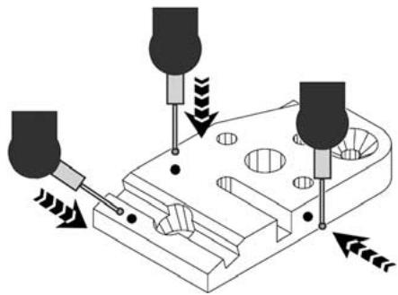
Probing points
When probing part features using a touch probe:
- Approach the surface at 90 degrees.
- Approach the surface without
changing direction in the last 5 mm.
- Do not drag the probe across the surface.
- Do not probe sharp edge transitions.
Leveling and aligning the part
Perform level and skew alignments to eliminate measurement errors resulting from misaligned parts.
1. Align the part on the stage
Align the reference edge of the part to a measurement axis.
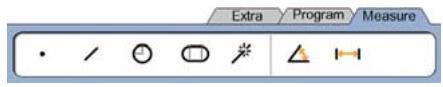
2. Level the part
- Touch the MEASURE tab to display the 3D measure icons, and then touch the PLANE icon.
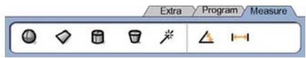
Probe a minimum of 3 points on the desired part reference-plane surface and then press the FINISH key.
- Touch the ALIGN and ZERO buttons on the DRO screen to level the plane at Z = 0 .
Operation
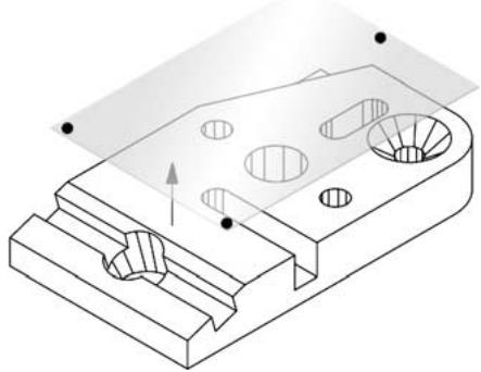
3. Perform a skew alignment
- Touch the MEASURE tab to display the 2D measure icons, and then touch the LINE icon.
Probe a minimum of 2 points on the reference edge surface of the part and then press the FINISH key.
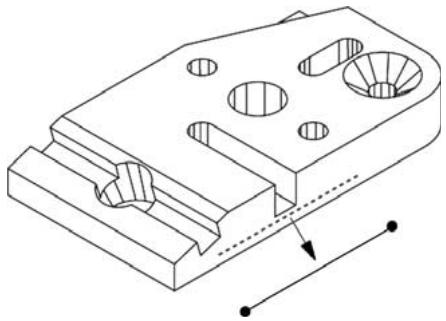
- Touch the ALIGN button on the DRO screen to align the reference edge.
Creating a zero datum
Probe, construct or create a reference point and press the ZERO buttons for each axis on the DRO screen.
Presetting a datum
Probe, construct or create a reference point, touch the axis values shown on the DRO screen and enter preset values using the numeric keypad.
Saving the reference frame
The reference frame for measurements must be saved once the part is leveled, aligned and a datum has been established.
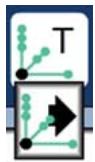
- Touch the REFERENCE FRAME icon and then touch the SAVE arrow icon. The reference frame will be saved and given a number.
Selecting a projection plane
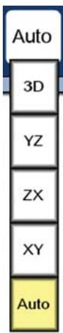
Projection planes are selected by the user or automatically by the ND 1400. Touch the PROJECTION button and then touch a projection plane icon:
- 3D: no projection plane is selected.
- XY, YZ or ZX planes
- Auto; ND 1400 selects a projection plane based on the probed points.
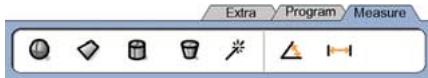
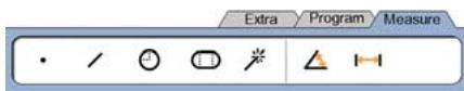
Measuring features
Features are measured by touching a feature icon or the MEASURE MAGIC icon in the 2D or 3D MEASURE tab, probing points and then pressing the ENTER and FINISH keys.
1. Measure a point
Touch the POINT icon and probe a point.

2.Measure a line
Touch the LINE icon and probe a minimum of 2 points.
3.Measure a circle
Touch the CIRCLE icon and probe a minimum of 3 points in any order around the circumference in any order.

4.Measure an arc
Touch the CIRCLE icon once to display the ARC icon, then touch the ARC icon and probe a minimum of 3 points in sequence from beginning to end of the arc.
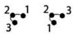
5.Measure a slot
Touch the SLOT icon and probe 5 points in the following sequence:
- Two points on a long side
One point in the closest end - One point in the center of the second long side
- Last point on the remaining end
Points can be probed in sequence in either direction.


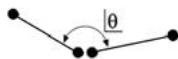
6.Measure an angle
Touch the ANGLE icon and probe a minimum of 2 points on each of the two legs. Press the FINISH key after each leg.
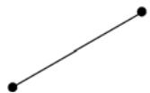
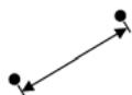
7.Measure a distance
Touch the DISTANCE icon and probe 1 point on each end of the distance.


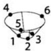
8.Measure a sphere
Touch the SPHERE icon and probe a minimum of 4 points around the surface of the sphere in any order.


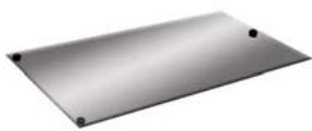
9.Measure a plane
Touch the PLANE icon and probe a minimum of 3 points on the surface of the plane.

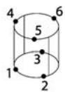
10. Measure a cylinder
Touch the CYLINDER icon and probe 3 points around one end circumference, 3 points around the other end circumference and then any desired additional points.
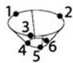
11. Measure a cone
Touch the CONE icon and probe 3 points around one end circumference, 3 points around the other end circumference and then any desired additional points.
12. Use Measure Magic
Touch the MEASURE MAGIC icon and probe points on a feature. The feature type will be determined based on the pattern and sequence of point probing.

Creating Features
Features are created by selecting the feature type to be created, entering the required feature data and then pressing the FINISH key.
1. Specify the feature type
Touch the MEASURE tab and then touch a measure icon to specify the type of feature to be created.
2. Enter the feature data
Touch the ENTER DATA icon and then enter data into fields shown on the screen.

3.Complete the creation
Press the FINISH key to complete the feature creation. The new created feature will be shown in the feature list.
Constructing Features
Features are constructed by selecting the feature type to be constructed, selecting the parent features and then pressing the FINISH key.
1. Specify the feature type
Touch the MEASURE tab and then touch a measure icon to specify the type of feature to be constructed.
2. Select the parent features
Touch the desired parent features in the feature list. Check marks will be shown near the parent features.
3. Complete the construction
Press the FINISH key to complete the construction. The new constructed feature will be shown in the feature list.
Viewing measurement data
Probed data points with form errors are viewed by selecting a feature in the feature list and touching the VIEW button.
1. Select a feature
Touch the desired feature in the feature list.
2. Press the VIEW button
Form errors are displayed as lines extending from data points to the feature. The two greatest form errors are shown in red.

Applying Tolerances
Tolerances are applied by selecting a feature, touching the TOL button, selecting a tolerance type and entering tolerance data.
1. Select a feature
Touch the desired feature in the feature list.
2. Press the TOL button
Tolerance types are displayed at the bottom of the screen as tolerance icons.
3. Select a tolerance
Touch a tolerance icon to select the desired tolerance type and then touch the word TOLERANCE at the top left corner of the screen to select a specific tolerance.
4. Enter tolerance data
Enter NOMINAL and TOLERANCE data into data fields provided in the tolerance screen.
5.View the result
Green squares near features in the feature list indicate passed tolerances. Red squares and outlined characters on the DRO screen indicate failed tolerances.
Programming
Programs are recorded sequences of measurement and other operator activities stored by the ND 1400 to be played back later when inspecting identical parts. This guide discusses recording, running, saving, loading and deleting programs.

Note:
Programs can also be copied and edited. Refer to the User's Guide for detailed information.
1. Record a program
- Touch the PROGRAM tab.
- Touch the round red RECORD icon.
- Enter a program name and press the FINISH key to begin recording.
- Perform measurement and other steps as usual. Program recording is indicated by a red program tab.
- To end recording, press the PROGRAM tab and then press the square black STOP icon. The new program will be stored.
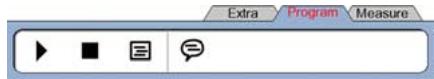
- Press the FINISH key to end the programming session and return to the DRO.
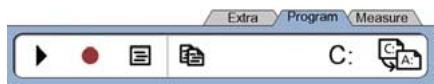
2. Running a program
- Touch the PROGRAM tab.
- Touch a program name.
- Press the black triangular RUN icon. The feature type and points probed will be displayed as points are probed.
After establishing a reference frame, press the VIEW soft key to see point targeting while points are probed. - The program will stop automatically when all program steps have been played. A message box will be displayed.
- Touch the message box to end the programming session and return to the DRO.
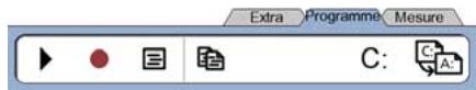
Saving programs
Programs can be saved to a USB drive.
- Plug an empty USB drive into the USB port on the side of the ND 1400.
- Touch the PROGRAM tab and touch the program name.
- Touch the COPY PROGRAM icon.
- Press the FINISH key to return to the DRO.
Loading programs
Programs can be loaded from a USB drive.
- Plug the USB drive into the USB port on the side of the ND 1400.
- Touch the C: DRIVE icon to change drives. The A: (USB) DRIVE icon and list of programs stored on the USB drive will be shown,
- Touch the desired program name in the list and then touch the LOAD PROGRAM icon. The highlighted program will be loaded to the local (C:) drive.
- Touch the DRIVE icon. The C: DRIVE will be shown with the loaded program in the C: DRIVE program list.
The loaded program can now be selected and run.
3. Deleting a program
- Touch the PROGRAM tab.
- Touch a program name.
- Press the CANCEL key. The program will be deleted.

Note:
Use caution when deleting programs, and store a backup of the program first. Deleted programs cannot be restored.
- Press the FINISH key to end the programming session and return to the DRO.
Reporting Results
Reports of results can be sent to a USB printer, USB flash drive or a PC. The report type and destination are specified in the PRINT setup screen.

Note:
Refer to the ND 1400 user guide on our web site at: www.heidenhain.de for details.
- Press the SEND key to report results.

- Toucher I'onglet PROGRAMME.
IodroTOBka K n3MepeHnA M
1.BkIoueHne ND 1400
CoxpaHHe nCHTeMbI KOOpDInHaT
Iocne toro, KaK DeTaJIb BbIpOBHeHa n DaHbIe 3aФИКСИРОВaHbI, CnCTema KOOpDInHaT dJa I3MepeHnДOnxHa 6bITb CoXpaHeHa.
- Bыберпгу Иконky СИСТЕмAKOOPДИНATи ПOTOMИКОнHуCO STpeЛКоI COXPAHHTb/SAVE. СИСТЕма KoopДинat 6удeт coхpaHeHa n ei 6уdET псИСВоEн HOMeR.
BbI6Op IIOsCKoCTn IpoEkuN
| A | LCD | ||
| B | |||
| C | |||
| D | |||
| E | USB | PC | |
| F | LCD | / | LCD |
| 1 | |
| 2 | |
| 3 | |
| 4 | X Y Z Q |
| 5 | RS-232-C PC RS-232 |
| 6 | 15 |
| 7 | 5 |
| 8 | RJ-45 |
| 9 |
| 10 | 3.5 / 8 Ohm | |
| 11 | A | USB |
| 12 | ||

ND 1400
HEIDENHAIN
Technical support FAX) +49 8669 32-1000
Measuring systems +49 8669 31-3104
E-mail: service.ms-support@heidenhain.de
TNC support
+49866931-3101
E-mail: service.nc-support@heidenhain.de
NC programming +49 8669 31-3103
E-mail: service.nc-pgm@heidenhain.de
PLC programming +49 8669 31-3102
E-mail: service.plc@heidenhain.de
Lathe controls
+49 8669 31-3105
E-mail: service.lathe-support@heidenhain.de
For complete and further addresses see www.heidenhain.de
B1653AOX Villa Ballester, Argentina
www.heidenhain.com.ar
AU FCR MotionTechnology Pty. Ltd
Laverton North 3026, Australia
E-mail: vicsales@fcrmotion.com
BA Bosnia and Herzegovina SL
BE HEIDENHAIN NV/SA
1760 Roosdaal, Belgium
www.heidenhain.be
BG ESD Bulgaria
Sofia 1172, Bulgaria
www.esd.bg
BR DIADUR Industria e Comercio Ltda.
04763-070 - São Paulo - SP, Brazil
www.heidenhain.com.br
BY Belarus
50354 Huerth, Germany
www.gertner.biz
CA HEIDENHAIN CORPORATION
Mississauga, OntarioL5T2N2, Canada
www.heidenhain.com
Beijing 101312, China
102 00 Praha 10, Czech Republic
www.heidenhain.cz
DK TPTEKNIKA/S
2670 Greve, Denmark
www.tp-gruppen.dk
ES FARRESA ELECTRONICA S.A.
08028 Barcelona, Spain
www.farresa.es
FI HEIDENHAIN Scandinavia AB
02770 Espoo, Finland
www.heidenhain.fi
FR HEIDENHAIN FRANCE sarl
92310 Sèvres, France
www.heidenhain.fr
GB HEIDENHAIN (G.B.) Limited
Burgess Hill RH15 9RD, United Kingdom
www.heidenhain.co.uk
GR MB Millionis Vassilis
17341 Athens, Greece
www.heidenhain.gr
HK HEIDENHAIN LTD
Kowloon, Hong Kong
E-mail: service@heidenhain.com.hk
HR Croatia SL
HU HEIDENHAIN Kereskedelmi Kepviselet
1239 Budapest, Hungary
www.heidenhain.hu
ID PT Servitama Era Toolsindo
Jakarta 13930, Indonesia
E-mail: ptset@group.gts.co.id
IL NEUMO VARGUS MARKETING LTD.
Tel Aviv 61570, Israel
E-mail: neumo@neumo-vargus.co.il
IN HEIDENHAIN Optics & Electronics
India Private Limited
Chennai-600 031,India
www.heidenhain.in
IT HEIDENHAIN ITALIANA S.r.l.
20128 Milano, Italy
www.heidenhain.it
JP HEIDENHAIN K.K.
Tokyo 194-0215, Japan
www.heidenhain.co.jp
KR HEIDENHAIN Korea LTD.
Gasan-Dong, Seoul, Korea 153-782
www.heidenhain.co.kr
ME Montenegro SL
MK Macedonia BG
MX HEIDENHAIN CORPORATION MEXICO
20235 Aguascalientes, Ags., Mexico
E-mail: info@heidenhain.com
MY ISOSERVE Sdn. Bhd
56100 Kuala Lumpur, Malaysia
E-mail: isoserve@po.jaring.my
7300 Orkanger, Norway
www.heidenhain.no
PH Machinebanks Corporation
Quezon City, Philippines 1113
E-mail: info@machinebanks.com
PL APS
02-489 Warszawa, Poland
www.apserwis.com.pl
PT FARRESA ELECTRONICA, LDA.
4470 - 177 Maia, Portugal
www.farresa.pt
RO HEIDENHAIN Repezenta Romania
Braşov, 500338, Romania
www.heidenhain.ro
RS Serbia BG
RU OOO HEIDENHAIN
125315 Moscow, Russia
www.heidenhain.ru
SE HEIDENHAIN Scandinavia AB
12739 Skärholmen, Sweden
www.heidenhain.se
SG HEIDENHAIN PACIFIC PTE LTD.
Singapore 408593
www.heidenhain.com.sg
SK KOPRETINATN s.r.o.
91101 Trencin, Slovakia
www.kopretina.sk
Bangkok 10250, Thailand
www.heidenhain.co.th
TR T&M Muhendislik San. ve Tic. LTD. STI.
34728 Umraniye-Istanbul, Turkey
www.heidenhain.com.tr
TW HEIDENHAIN Co., Ltd.
Taichung 40768, Taiwan R.O.C.
Midrand 1685, South Africa
www.heidenhain.co.za