
ND 2100G - Industrial measuring instrument HEIDENHAIN - Free user manual and instructions
Find the device manual for free ND 2100G HEIDENHAIN in PDF.
| Product type | Industrial measuring instrument |
| Brand | HEIDENHAIN |
| Model | ND 2100G |
| Power supply | Voltage: 100 V~ to 240 V~ (-15% to +10%), frequency: 43 Hz to 63 Hz, fuse: T1600 mA, 250 V, 5 × 20 mm |
| Display | LCD screen with soft keys |
| Encoder inputs | 4 inputs for encoders, interface specific to control |
| Relay outputs | 2 relay contacts, max voltage 100 V, max switching current 250 mA, permissible current 500 mA, breaking capacity 3 W, static resistance 0.20 Ω |
| Parallel I/O port | Standard TTL levels |
| RS-232-C interface | For connection to a PC, straight-through cable |
| Audio output | 3.5 mm jack, monaural, 8 Ω |
| USB interface | Type A for printer or data backup |
| Remote control interface | RJ-45 for foot switch and keypad, up to 2 accessories via splitter |
| Main functions | Dimension display, graphs, histograms, bar charts, dials, data tables and SPC statistics, dimension formulas, tolerances, reports |
| Dimension formulas | Creation of complex formulas using mathematical functions (max, min, etc.) to process encoder inputs |
| Tolerances | Specification of nominal values, monitoring, limits and max, with audible alarm |
| Backup and restore | On USB stick via SAVEX and LOADX keys |
| Safety instructions | Do not open the housing; do not use a 3-wire/2-wire adapter; do not connect encoders while powered; power cable replaced only by a qualified electrician |
| Maintenance | Data backup battery replacement |
Frequently Asked Questions - ND 2100G HEIDENHAIN
User questions about ND 2100G HEIDENHAIN
0 question about this device. Answer the ones you know or ask your own.
Ask a new question about this device
Download the instructions for your Industrial measuring instrument in PDF format for free! Find your manual ND 2100G - HEIDENHAIN and take your electronic device back in hand. On this page are published all the documents necessary for the use of your device. ND 2100G by HEIDENHAIN.
USER MANUAL ND 2100G HEIDENHAIN
Electrical connection
Line voltage: 100V to 240V
(-15% to +10%)
Line frequency: 43 Hz to 63 Hz
Line fuse: T1600 mA, 250 V
5 × 20 ~mm
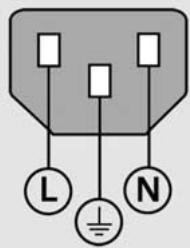
Power connector wiring
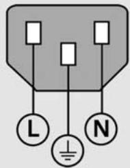
L: Line voltage (brown)
N: Neutral (blue)

Earth ground (yellow/green)

Danger of electrical shock!
- Do not open the enclosure.
- Never use 3-wire to 2-wire adapters or allow the ground connection to the ND 2100G to be interrupted or disconnected.

Caution
Changes to the power cable may be made only by an electrical technician.

Caution
Do not connect encoders or other equipment to the ND 2100G when the power is on.
Safety Considerations
General accepted safety precautions must be followed when operating the ND 2100G. Failure to observe these precautions could result in damage to the equipment, or injury to personnel. It is understood that safety rules within individual companies vary. If a conflict exists between the material contained in this guide and the rules of a company using this system, the more stringent rules should take precedence.
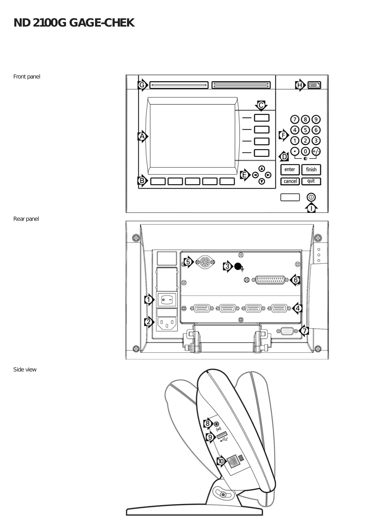
Controls and Displays
| A | LCD screen |
| B | Soft keys change to support functions. |
| C | Dimension keys display dimension values or graphs. |
| D | Command keys control measurement activities. |
| E | Arrow cursor keys for menu navigation. |
| F | Numeric keypad for entering numeric data. |
| G | Fast track keys are programmable for frequently used functions. |
| H | Send key transmits data to a PC, USB printer or USB drive. |
| I | LCD on/off key turns the LCD on or off or clears stored data. |
Connections rear side
| 1 | Power switch |
| 2 | Power connection with fuse |
| 3 | Ground (protective ground) |
| 4 | Encoder inputs are inputs for dimension formulas. The encoder interface is specified at the time of purchase. |
| 5 | Relay outputs are two sets of signalling relay contacts that open and close under the control of ND 2100G formulas. Caution • Max contact voltage: 100V • Max contact switching current: 250 mA • Max contact carry current: 500 mA • Contact rating: 3 Watts • Static contact resistance: 0.20 Ohms |
| 6 | Parallel I/O port reads and writes standard TTL levels under the control of ND 2100G formulas. |
| 7 | RS-232-C interface for PC connection. RS-232 cable must not include crossovers. |
Connections side view
| 8 | Audio out, for 3,5 mm headphone /speaker jack, monaural, 8 Ohm |
| 9 | USB Type A interface for printer or data storage. |
| 10 | Remote accessory interface RJ-45 for optional foot switch or keypad accessory. Two optional remote accessories can be used simultaneously using an RJ-45 splitter. |
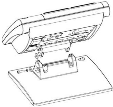
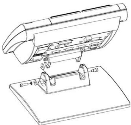
Mounting
The ND 2100G is secured to the swivel slots of the mounting stand or arm mount by a shoulder screw, a cap screw mount is shown with associated washers.
Very important
Please note
For your information
HEIDENHAIN
The LCD displays a variety of screens selected by the user to show current dimension values, pass/fail test results, dimension value graphs, statistical process control graphs or data tables, and setup options. Navigate from one screen to another using the soft keys under the LCD.
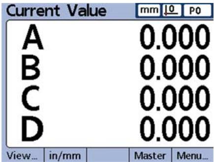
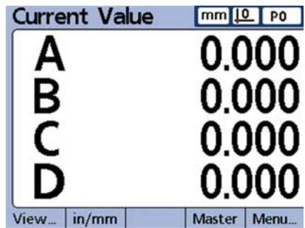
Current value screen
The Current Value screen is displayed after power is applied and the startup screen is shown. Current values of up to 4 dimensions are shown. The unit of measure, current datum and current part number or part name are displayed in the upper right corner of the screen.
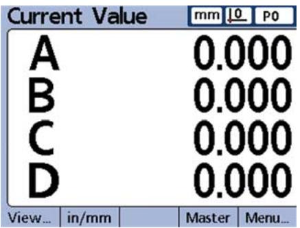
Use the CURSOR ARROW keys to scroll dimensions when more than 4 dimensions are active. Press the DRO soft key to display the Current Value screen from other screens.
View screens
Press the View soft key to display:
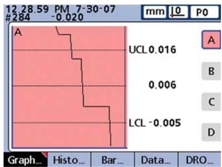
Graphs of dimension value history
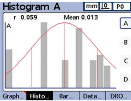
- Histograms dimension values
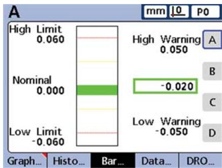
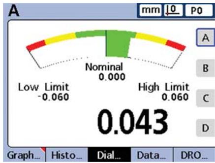
- Bar or dial displays of current values
Data tables and statistics
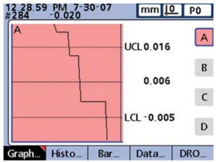
Graphs
Press the GRAPH soft key to show graphs of dimension values.
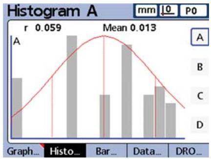
Histograms
Press the HISTOGRAM soft key to show graphs of dimension values.
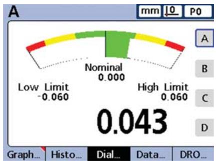
Bar and dial displays
The choice of a bar or dial display is made in the Display setup screen.
Press the BAR soft key to show a bar graph of dimension values.
Press the DIAL soft key to show a dial of dimension values.
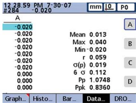
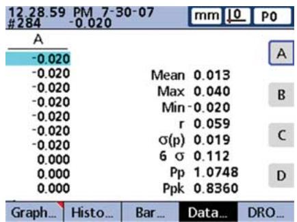
Data tables and statistics
Press the DATA soft key to show a data table with SPC statistics.
Initial power up
- Press the POWER SWITCH to power the ND 2100G. The startup screen is displayed.
ND 2100G
- Press the FINISH key to display the current dimension values on the Current Value screen.
Software setup
The operating parameters of the ND 2100G must be configured prior to using it for the first time, and any time part measurement, reporting or communication requirements change.
Settings will be retained until:
- The data-backup battery is changed
- The data and settings are cleared
- Software upgrades are performed

Caution
Setup parameters control the operation of the ND 2100G and are password-protected. Only qualified personnel should be given password access to setup screens.
1. Display the setup menu
- Press the MENU soft key to display menu items above the soft keys.
- Press the SETUP soft key to display the setup menu on the left side of the LCD screen.
View... in/mm Datum... Extra Setup
- Use the CURSOR ARROW KEYS to Navigate the setup menu and to highlight selections.
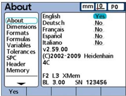
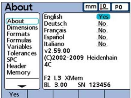
2. Select the language
Highlight the desired language and then press the YES soft key.
3. Enter the Supervisor Password
Navigate to the SUPERVISOR screen and enter the supervisor PASSWORD.
4. Configure encoders
- Navigate to the CHANNELS screen and highlight the desired encoder CHANNEL.
- Enter all the required encoder parameters.
- Repeat setup for all encoder channels. Select other channels using the DEC or INC soft keys. If desired, apply settings from the current channel to all others using the APPLY ALL soft key.
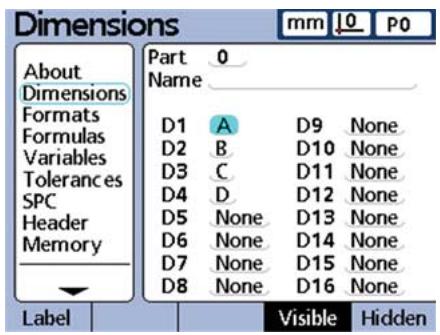
5. Name parts and dimensions
- Navigate to the DIMENSIONS screen and highlight the PART field.
- Select other parts using the DEC or INC soft keys. Press the NEW soft key to add a new part.
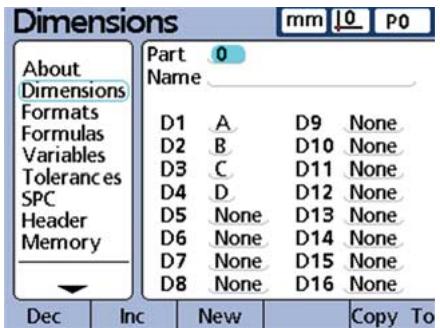
- Highlight the NAME field.
- Parts can be referenced by number or name. If desired, press the LABEL soft key to name the current part
Highlight the first dimension of the part.
- Retain the default dimension name or press the LABEL soft key to rename the dimension.
- Highlight and rename remaining dimensions as desired.
6. Configure the LCD display
Navigate to the DISPLAY screen and select the desired display characteristics.
7. Configure display formats
- Navigate to the FORMATS screen and highlight the DIMENSION field.
- Enter the desired display parameters for the dimension.
- Repeat setup for all dimensions. Select individual dimensions using the DEC or INC soft keys or apply settings from the current dimension to all others using the APPLY ALL soft key.
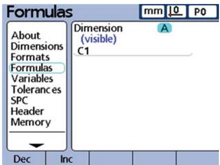
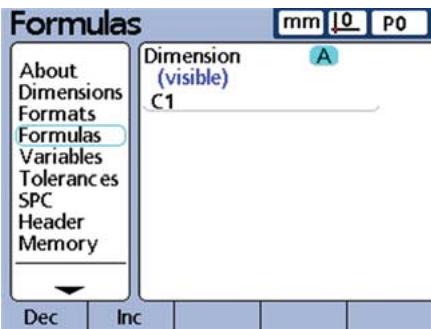
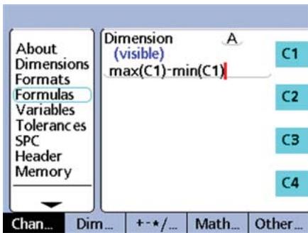
8. Create dimension formulas
The ND 2100G uses formulas to convert encoder channel inputs to the dimension values shown on the screen.
Default dimension formulas shipped with the ND 2100G simply show the input encoder channel values as in this example of dimension A, which is given the value of encoder channel C1:
$$ A = C 1 $$
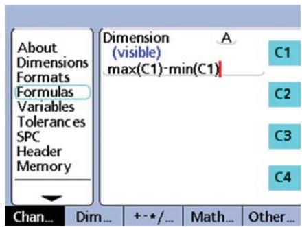
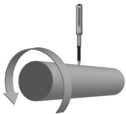
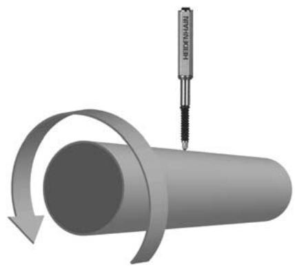
More complex formulas are created in the FORMULAS setup screen that process one or more encoder input channels to produce sophisticated measurements. In this example, encoder channel C1 is used in max and min functions to produce a runout measurement of a rotating rod:
$$ A = \max (C 1) - \min (C 1) $$

To create a formula:
- Navigate to the FORMULAS screen and select the desired DIMENSION using the DEC or INC soft keys.
- Navigate down to the formula line and enter a formula using the functions displayed on the right side of the screen. Formula functions are changed using the soft keys at the bottom of the screen.

Note:
The ND 2100G includes a wide range of basic and advanced formula functions. Refer to the User's Guide for detailed information.
Preparing to measure
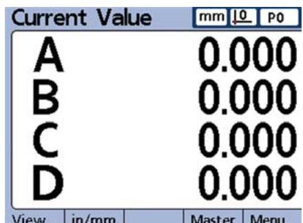
1. Power up the ND 2100G
- Check connections to the ND 2100G.
- Press the POWER SWITCH to power the ND 2100G. The CURRENT VALUE screen will be displayed after system initialization.
| Current Value | mm | 10 | P0 | |
| A | 0.000 | |||
| B | 0.000 | |||
| C | 0.000 | |||
| D | 0.000 | |||
| View... | in/mm | Master | Menu... | |
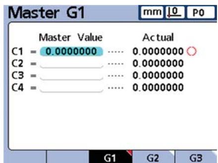
2. Establish a measurement reference
Establish references for encoder channels prior to measuring.
To establish a measurement reference:
- Press the MASTER soft key to display the Master screen.
- Navigate to the desired encoder channel MASTER VALUE field.
- Position the encoder against the reference surface.
- Enter the desired reference value (zero or the desired offset) into the MASTER VALUE field.
| Master G1 | mm | L0 | P0 | |
| Master Value | Actual | |||
| C1 = | 0.0000000 | 0.0000000 | ○ | |
| C2 = | 0.0000000 | |||
| C3 = | 0.0000000 | |||
| C4 = | 0.0000000 | |||
- Press the ENTER key and respond to the confirmation request. A green dot will appear next to the ACTUAL value indicating that calibration of the channel is complete.
Conducting measurements
1. Probe surfaces
Probe a single point with one encoder channel, or multiple points simultaneously with multiple encoder channels.
2. Enter the measurement data
Press the ENTER key when measurements are displayed on the LCD. The measurement data will be entered into the ND 2100G database.

Note:
Advanced formula functions can be used to perform sequential and semi-automated measurements. Refer to the User's Guide for detailed information.
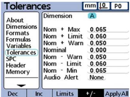
Applying Tolerances
1. Select a dimension
- Press the MENU soft key then press the SETUP soft key to display the setup menu.
- Navigate to the Tolerances screen and select the desired DIMENSION using the DEC and INC soft keys.
| Tolerances mm L0 P0 | ||
| About | Dimension A | |
| Dimensions | Nom + Max 0.065 | |
| Formats | Nom + Limit 0.060 | |
| Formulas | Nom + Warn 0.050 | |
| Variables | Nominal 0.000 | |
| Tolerances | Nom - Warn 0.050 | |
| SPC | Nom - Limit 0.060 | |
| Header | Nom - Min 0.065 | |
| Memory | Audio Alert None | |
2. Specify tolerance values
- Enter the NOMINAL, WARNING, LIMIT and MAX values.
- Navigate to the AUDIO ALERT field and use the soft keys to select NONE, WARNING or LIMITS.

Note:
Many types of tolerances can be applied to dimensions. Refer to the User's Guide for detailed information.
Viewing measurement data
Measurement results can be viewed in the graphs, histograms and data tables as described earlier. Refer to the User's Guide for more details.
Reporting Results
Result data can be sent to a USB printer, USB drive or a PC. The report format, type and destination can be changed in setup screens. The default setup is shown below.
To print: press the PRINT key to send data to the USB port.
To send data to a PC:
- Press the MENU soft key to display menus under the LCD.
- Press the EXTRA soft key to display the Extra menu.
- Highlight the SEND function and press the ENTER key to transmit data over the RS-232 port.

Cycle
DMS/DD
Fast3
Hold
Part?
Rad/Dia
Recall
RsetDyn
Send
SendRec

Note:
Refer to the ND 2100G user guide for alternatives regarding printing and transmitting data.
Saving and retrieving data
ND 2100G settings and measurement data can be backed up on a USB drive and restored to the system or loaded on another identical system later. To save or retrieve data:
- Insert a USB drive into the NG 2100G
- Press the MENU soft key and then press the SETUP soft key to display the setup menu.
- Navigate to the Supervisor screen and highlight the PASSWORD field. Enter the password if necessary.
- Press the SAVEX soft key to save settings and measurement data.
- Press the LOADX soft key to retrieve settings and data.

Note:
Frequently used functions can be mapped to front panel keys using the Hot Key function explained in the User's Guide.
$$ A = \max (C 1) - \min (C 1) $$

Formel konstruieren:
$$ A = \max (C 1) - \min (C 1) $$

$$ A = \max (C 1) - \min (C 1) $$

$$ A = \max (C 1) - \min (C 1) $$

The ND 2100G is secured to the swivel slots of the mounting stand or arm mount by a shoulder screw, a cap screw mount is shown with associated washers.
$$ A = \max (C 1) - \min (C 1) $$

Scherm Current Value
$$ A = \max (C 1) - \min (C 1) $$

Een formule make:
$$ A = \max (C 1) - \min (C 1) $$
$$ A = \max (C 1) - \min (C 1) $$

Para Criar a formula:
$$ A = \max (C 1) - \min (C 1) $$

3a3eMJIeHne (JKeJTbIy/3eJIeHbI)

Onachocb ydapa TOKOM!
- He OTKpbIbAaTe npu6Op.
- Hikorda He nCnoIb3yIte 2-x npoBODHO aanTep BmecTo 3-x npoBODHOrO n He dOnyckaiTe pa3pbIBa IIIN OTKnIOueHnKa6eJIa 3aemJeHn ND 2100G.

BHMaHne
I3meHnB KaBeJe NITaHnMOryT IpoIN3BOIDHTCBc TOnbKOIpOceCCNOHaNbHbIM 3JekTpKOM.

BHHMaHne
He npoklnoayte n3mepntelbHbIe daTnKn nn Dpyrne npnbopbl K ND 2100G, korga on Bklnoueh.
06ecneueHne 6e3oNaCHOCTn
Ppna p6oTe c ND 2100G DeiCTbYIO T npn3HaHHbIe MepbI IO oBeCneHEnIO 6e3OanachocTn. HecobJIOJeHne 3TNX MEP MoKET npVBecTn K NOBpeKDeHNIO npnbopa nIIN TpaBMam. Pa3yMeTcR, MepbI oBeCneHEnN 6e3OanachocTn MOrTy pa3JIuHTbcra B pa3HbIX KOMNaHnAx. B cnUyae OTNIuN BByTpEHNx PpABNJ KOMNaHnN, B KOTOpOI NcIOnJIb3yETc DaHbI Ipn6Op, OT ppeDnIcaHn KpaTKOrO pyKOBoIDCTBa DeiCTbYIO BoJee CTporne npabina.
Зкрази злем entblуnpaBneHnA
| A | LCD MOHITOP |
| B | Softkey MHOOROΦUHKQUHOHAJIbHbIe Клавиши, 3aВИСТ OT ФУнКCUIM |
| C | Кнорки КООрДИНAT OTOBражЕнUE 3HAчЕнИ KOОрДИНAT ИПΙ ГАФИКOB |
| D | Кнорки KOMaHД упраВЛЕнUE ИЗМерЕнЯМИ |
| E | Кнорки CO STРЕКAMN НавИГAZИЙ ПО MEЮ |
| F | ЦИФROВая KЛавиатура ВВОД ЦИФROВых 3HAчЕнИ |
| G | Кнорки БьICTPORA ДOSTУNA ПрогаммИPyюТСЯ РODЧАСТО ИСПОЛБУЕМБIE ФУнКCUIM |
| H | Кнорka OTПРABINTь пeredача ИЗМерЕньИХ 3HAчЕнИ На ПК, USB-прип deterи USВ- НakОПИТЕЛь |
| I | Кнорka LCD BкЛ/ВьIKЛ ВКПЮЧЕНUE ИПΙ ВьКПЮЧЕНUE MOHITOPA, удале"HUE ДaHHbIX |
Pa3bembl Ha 3aHne naneJn
- PezylbTaTbI n3MepeHnHaDnarpamme
- PezylbTaTbI N3MepeHnHa rntCTOrpAmme
- Tekyuüne 3nauéHnB BnDE 6aJIKN "Bar" nIu IkuNbl "Dial"
- Ta6nIyI daHbIX IN CTaTnCTnKa
Diarpamma
Haxmnte Softkey GRAP,TO6bI OTo6pa3ntb pe3yJbTaTb I3MpeHn B BVNe DnAqrPAMMbI.
Tnctorpamma
Haxmte Softkey HISTOGRAM, yTo6bl OTo6pa3ntb pe3yIbTaTbI n3MepeHn B BVnde INCTOrpaMMbl.
Bajka n ukaJa
OTo6paKeHne DaHHbIX B BVNe 6aJIKN IINI WkaJIbI Bbl6nPaetcB PnyHKTe MeHIO VIEW
Hakmnte Softkey BAR, yTo6bl OTo6pa3ntb pe3yIbTaTbI n3MepeHn B BVnde 6aKn.

Haxmnte Softkey DIAL, yTo6bI OTo6pa3ntb pe3yJIbTaTbI n3MepeHn B BVNe 1kaJIbI.
Ta6nucbI daHHbIX n ctaTnCTnka Haxmnte Softkey DATA, yTo6bl OTo6pa3ntb pe3yJIbTaTb I3MpeHn B BVide Ta6nucbI CO cTaTnCTnueCKIMn DaHHbIMN.
PepBoe BkIouHeHne
BknHouTe BbIKIIOUATEJIb IITAHINdIy3ayncka ND 2100G. Ha 3kpane oTo6pa3ntc3acTabka.
ND 2100G
- Haxmte KhoNky FINISH dny OTo6paXeHnY TeKuInx KoOpDnHaT NOLOKeHnO cEi.
HactpoynnIO
Ipaametpbi ND 2100GdoJIKNbI
6bItb ONpeJeHbI nepeI nepBbIM
NCIOJIb3OBAHEm, INx HEoBXODMO
HaCTpaINBaT kaxDbI pa3 npN
n3MeHeHH Tpe6OaHm K n3MepeHnA M
NJn PepeDaU daHbIX.
HactpoiKo coxpanaTcTdo:
-
Cmehb6aTapepepeepBbIX KOIN
-
ydaJIeHnI DaHHbIX N HaCTpoEK
-
06HOBJIeHnI ΠΟ

BHMaHne
HacpoKn napameTPOB ynpaBnAHT pa60ToN ND 2100G n 3aunueneHbI npoJIe.M. NapOJIb dIy IocTypa K 3TNM HacPoRkam DoJKeH nepeDaBaTbcr ToIbKO KBaINΦnUropOBaHHOMy nepcoHaNy.
1.Отообрахени MeHIO HaCTpoEK
- Haxmnte Softkey MENU, yTo6bI oTo6pa3ntb cyHkCmKnaBnS Softkey.
- Haxmnte Softkey SETUP, yTo6bl OTKpbIb IyHKtbl MeHIO HaCTpoKn.
View... in/mm Datum... Extra Setup
-Перевогатесь мжду пнктамMuMeHc nOMOUsb KHOPIOKCOCTPEJIKAMUиВыдяЯTeJxelaembIepyHKtbl/NoIy.
2.Bb6opЯ3bika
Bb6epnte keaembl y3bIK n HaxMnTe Softkey YES.
3. Bvod napoi.
BbIbePte NyHKT MeHIO SUPERVISOR n BBeIte napOJIb B nOle PASSWORD.
4. Hac tropon KaTnKOB
$$ A = \max (C 1) - \min (C 1) $$

UTo6b3aDaTbΦoMpMyIy:
IoproTOBka K n3MepeHnAeM
1. BkIIOueHne ND 2100G
- Поверп Te посоeДиЕнЯ
ND 2100G.
BknHouTe BbIKIIOUATEJIb IINTAHINЯДЯЗANyCsA ND 2100G. Nocne INHuaJIn3aunHa nA ekpane OTo6pa3aTcR TEKUYIe KOOPDINHATbl.
| Current Value | mm | L0 | P0 | |
| A | 0.000 | |||
| B | 0.000 | |||
| C | 0.000 | |||
| D | 0.000 | |||
| View... | in/mm | Master | Menu... | |
2. Co3daIte npB8a3Ky dJa n3MepenH
Ipeudn3MepeHnMnДЯKaKdOrO DaTUnKa Heo6XoDmO CdeNaTb npVBra3ky.
UTo6bI CO3daTb PnIBa3ky IJIy n3MepeHn:
- Haxmnte Softkey MASTER, уTo6bI Bv3BaTb ФорMy BvoJa Master.
- Bыденитоле MASTER VALUE
- Кениаморо кандатунka.
- Позионуп Te Датчн Ка peферentHон NOBepxHoctN.
BVeIe XeJaemoe 3HaueHne npVBra3Kn (HOBn IJN CMeUeHne) B noJe MASTER VALUE.
| Master Value | Actual | |
| C1 = 0.0000000 | …… | 0.0000000 |
| C2 = | …… | 0.0000000 |
| C3 = | …… | 0.0000000 |
| C4 = | …… | 0.0000000 |
Haxmte KhONky ENTER n OTBeTbeHa noBvBwUeCBAponcbl.Bo3ne ACTUAL noBvTc3eJeha TOnka, KOtOpaO3NaHaet, YTO KaINbPobKa DaTHnka 3aKoHcyHa.
PpOBeHeHne n3MepeHn
1.OuynbIbAHne NOBepxHOCTN
KoCHNTecb OTdEJIbHOJ TOUKN ODNHM DaTChNKOM INN KOCHNTecb ODNHOBpeMeHHO HeCKOJIbKHX TOueK HECKOJIbKIMN DaTChKaMn.
2.BBOD daHHbIX n3MepeHn
Haxmnte KhoNky ENTER, kOgda pe3yNbTaTbI n3MpeHn OTo6pa3rTcHa 3KpaHe. DaHHbIe N3MpeHn BBeDyTcB 6a3y daHHbIX ND 2100G.

3ameuahne:
C NOMOUIH CIOXHbIX φOpMyI MOXHO BblONHbT bNOCJIeOBaTeIbHbIe I N OJyABTomATnueckne N3MpeHnI. Boone pOJpObHoe oNcAhnE MOxHO HaiTN BpyKOBOdCTBe N0lb3OBaTeJI.
Применец донуckов
1. BbI6op npn3naka
- Haxmite Softkey MENU, a 3aTem Softkey SETUP, yTo6bl OTkpblb MEHIO HAcTpoKn.
- Bыберпге пункт Meню Tolerances
- И Bыберпге залаимьй ризнak DIMENSIONс пою Softkey DEC nii INC.
| Tolerances mm L0 P0 | ||
| About Dimensions Formats Formulas Variables Tolerances SPC Header Memory | Dimension A Nom + Max 0.065 Nom + Limit 0.060 Nom + Warn 0.050 Nominal 0.000 Nom - Warn 0.050 Nom - Limit 0.060 Nom - Min 0.065 Audio Alert None | |
| 1 | Güç anahtarı | |
| 2 | Sigortal Güç böglantmiş | |
| 3 | Topraklama (koruyucu topraklama) | |
| 4 | Kodlayüncü girisleri, boyut formüllerinde kullanıan girdilerdir. Kodlayüncü arabirimi, satın alma anında belirlenir. | |
| 5 | Rôle çık,islanı, iki adet ND 2100G formüllerine®,®,®,®,®,®,®,®,®,®,®,®,®,®,®,®,®,®,®,®,®,®,®,®,®,®,®,®,®,®,®,®,®,®,®,®,®,®,®,®,®,®,®,®,®,®,®,®,®,®,®,®,®,®,®,®,®,®,®,®,®,®,®,®,®,®,®,®,®,®,®,®,®,®,®,®,®,®,®,®,®,®,®,®,®,®,®,®,®,®,®,®,®,®,®,®,®,®,®,®,®, Dikkat • Maks. kontak gerilimi: 100V • Maks. kontak anahtarlama akimi: 250 mA • Maks. kontaktaşima akimi: 500 mA • Kontak®,®,®,®,®,®,®,®,®,®,®,®,®,®,®,®,®,®,®,®,®,®,®,®,®,®,®,®,®,®,®,®,®,®,®,®,®,®,®,®,®,®,®,®,®,®,®,®,®,®,®,®,®,®,®,®,®,®,®,®,®,®,®,®,®,®,®,®,®,®,®,®,®,®,®,®,®,®,®,®,®,®,®,®,®,®,®,®,®,®,®,®,®,®,®,®,®,®,®,, • Kontak®,®,®,®,®,®,®,®,®,®,®,®,®,®,®,®,®,®,®,®,®,®,®,®,®,®,®,®,®,®,®,®,®,®,®,®,®,®,®,®,®,®,®,®,®,®,®,®,®,®,®,®,®,®,®,®,®,®,®,®,®,®,®,®,®,®,®,®,®,®,®,®,®,®,®,®,®,®,®,®,®,®,®,®,®,®,®,®,®,®,®,®,®,®,®,®,®,®,, 6 | Paralel I/O böglanti noktası ND 2100G formüllerine®,®, olarak standart TTL seviyelerini okur ve yazar. |
| 7 | PC böglant,is�能 RS-232-C arabirim. RS-232 kablosu capraz geç,is icermemelidir. |
$$ A = \max (C 1) - \min (C 1) $$

Formul olusturmak icin:
A = max(C1) - min(C1)

FORMULAS
INC
DEC
DIMENSION
Formula

:
ND 2100G
- ND 2100G
- ND 2100G
ND 2100G
CURRENT VALUE
2
- MASTER
Master
- VALUE
MASTER
- MASTER VALUE
- ENTER
ACTUAL
1.
1
2
ENTER
measurements
ND 210DG

1.
- MENU
SETUP
- Tolerances
INC MENSION
DEC
2
- NOMINAL, WARNING, LIMIT MAX
- AUDIO ALERT
LIMTS
NONE,WARNING

:
USB
PC
USB
USB

PC
-MENU
- EXTRA
Extra
SEND ENTER RS-232
Cycle
DMS/DD
Fast3
Hold
Part?
Rad/Dia
Recall
RsetDyn
Send
SendRec

:
ND 2100G
ND 2100G
USB
- NG 2100G USB
-MENU
SETUP
Supervisor
password
SAVEX
- LOADX

Hot Key
有關詳細說明,請參閱 www.heidenhain.de
開機之前
電氣連接
線電壓:100V~至240V~
(-15% 至 +10%)
線頻率:43 Hz至63 Hz
保險絲:T1600mA,250V
5x20mm
電力接頭配線
L:線電壓(棕色)
N:中性(蓝色)

接地(黄色/绿色)

觸電的危險!
$$ A = \max (C 1) - \min (C 1) $$
要產生新的公式:
Technical support FAX +49 866932-1000
Measuring systems +49 8669 31-3104
E-mail: service.ms-support@heidenhain.de
TNC support +49 8669 31-3101
E-mail: service.nc-support@heidenhain.de
NC programming +49 8669 31-3103
E-mail: service.nc-pgm@heidenhain.de
PLC programming +49 8669 31-3102
E-mail: service.plc@heidenhain.de
Lathe controls +49 8669 31-3105
E-mail: service.lathe-support@heidenhain.de
www.heidenhain.de
For complete and further addresses see www.heidenhain.de
B1653AOX Villa Ballester, Argentina
www.heidenhain.com.ar
AU FCR MotionTechnology Pty. Ltd
Laverton North 3026, Australia
E-mail: vicsales@fcrmotion.com
BA Bosnia and Herzegovina SL
BE HEIDENHAIN NV/SA
1760 Roosdaal, Belgium
www.heidenhain.be
BG ESD Bulgaria
Sofia 1172, Bulgaria
www.esd.bg
BR DIADUR Industria e Comercio Ltda.
04763-070 - São Paulo - SP, Brazil
www.heidenhain.com.br
BY Belarus
50354 Huerth, Germany
www.gertner.biz
CA HEIDENHAIN CORPORATION
Mississauga, OntarioL5T2N2, Canada
www.heidenhain.com
Beijing 101312, China
102 00 Praha 10, Czech Republic
www.heidenhain.cz
DK TPTEKNIKA/S
2670 Greve, Denmark
www.tp-gruppen.dk
ES FARRESA ELECTRONICA S.A.
08028 Barcelona, Spain
www.farresa.es
FI HEIDENHAIN Scandinavia AB
02770 Espoo, Finland
www.heidenhain.fi
FR HEIDENHAIN FRANCE sarl
92310 Sevres, France
www.heidenhain.fr
GB HEIDENHAIN (G.B.) Limited
Burgess Hill RH15 9RD, United Kingdom
www.heidenhain.co.uk
GR MB Millionis Vassilis
17341 Athens, Greece
www.heidenhain.gr
HK HEIDENHAIN LTD
Kowloon, Hong Kong
E-mail: service@heidenhain.com.hk
HR Croatia SL
HU HEIDENHAIN Kereskedelmi Kepviselet
1239 Budapest, Hungary
www.heidenhain.hu
ID PT Servitama Era Toolsindo
Jakarta 13930, Indonesia
E-mail: ptset@group.gts.co.id
IL NEUMO VARGUS MARKETING LTD.
Tel Aviv 61570, Israel
E-mail: neumo@neumo-vargus.co.il
IN HEIDENHAIN Optics & Electronics
India Private Limited
Chennai-600 031,India
www.heidenhain.in
IT HEIDENHAIN ITALIANA S.r.l.
20128 Milano, Italy
www.heidenhain.it
JP HEIDENHAIN K.K.
Tokyo 194-0215, Japan
www.heidenhain.co.jp
KR HEIDENHAIN Korea LTD.
Gasan-Dong, Seoul, Korea 153-782
www.heidenhain.co.kr
ME Montenegro SL
MK Macedonia BG
MX HEIDENHAIN CORPORATION MEXICO
20235 Aguascalientes, Ags., Mexico
E-mail: info@heidenhain.com
MY ISOSERVE Sdn. Bhd
56100 Kuala Lumpur, Malaysia
E-mail: isoserve@po.jaring.my
7300 Orkanger, Norway
www.heidenhain.no
PH Machinebanks Corporation
Quezon City, Philippines 1113
E-mail: info@machinebanks.com
PL APS
02-489 Warszawa, Poland
www.apserwis.com.pl
PT FARRESA ELECTRONICA, LDA.
4470 - 177 Maia, Portugal
www.farresa.pt
RO HEIDENHAIN Repezenta Romania
Braşov, 500338, Romania
www.heidenhain.ro
RS Serbia BG
RU 0OO HEIDENHAIN
125315 Moscow, Russia
www.heidenhain.ru
SE HEIDENHAIN Scandinavia AB
12739 Skärholmen, Sweden
www.heidenhain.se
SG HEIDENHAIN PACIFIC PTE LTD.
Singapore 408593
www.heidenhain.com.sg
SK KOPRETINATN s.r.o.
91101 Trencin, Slovakia
www.kopretina.sk
Bangkok 10250, Thailand
www.heidenhain.co.th
TR T&M Muhendislik San. ve Tic. LTD. STI.
34728 Umraniye-Istanbul, Turkey
www.heidenhain.com.tr
TW HEIDENHAIN Co., Ltd.
Taichung 40768, Taiwan R.O.C.
VN AMS Advanced Manufacturing
Solutions Pte Ltd
HCM City, Viet Nam
E-mail: davidgoh@amsvn.com
ZA MAFEMA SALES SERVICES C.C.
Midrand 1685, South Africa
www.heidenhain.co.za