
ND 1100 - Electronic measuring instrument HEIDENHAIN - Free user manual and instructions
Find the device manual for free ND 1100 HEIDENHAIN in PDF.
| Product type | Electronic measuring instrument with digital display |
| Brand | HEIDENHAIN |
| Model | ND 1100 |
| Power supply | 100–240 V AC (-15% to +10%), 43–63 Hz |
| Mains fuse | T1600 mA, 250 V, 5 × 20 mm |
| Display | LCD screen with softkeys |
| Measuring inputs | 4 axes (X, Y, Z, Q) for linear measurement systems and encoders |
| Communication interfaces | V.24/RS-232-C (serial), USB type A (printer/USB stick), RJ-45 (remote control) |
| Audio output | Headphone jack 3.5 mm, 8 Ω |
| Probe connection | Optional |
| Main functions | Position display, zero reset, preset, inch/mm switching, absolute/incremental modes, report printing, linear and segmented error compensation |
| Commissioning | Mains switch, FINISH key for display |
| Configuration | Password-protected SETUP menu; language, encoders, printing, squareness, scale, display format |
| Data backup | Internal battery for parameter retention |
| Safety | Do not open the device; protective conductor must not be interrupted; cable modification by qualified electrician |
| Maintenance | Clean with a dry cloth; replace battery by qualified personnel |
| Environmental conditions | Workshop use; follow internal safety instructions |
Frequently Asked Questions - ND 1100 HEIDENHAIN
User questions about ND 1100 HEIDENHAIN
0 question about this device. Answer the ones you know or ask your own.
Ask a new question about this device
Download the instructions for your Electronic measuring instrument in PDF format for free! Find your manual ND 1100 - HEIDENHAIN and take your electronic device back in hand. On this page are published all the documents necessary for the use of your device. ND 1100 by HEIDENHAIN.
USER MANUAL ND 1100 HEIDENHAIN
Quick Reference Guide
Kurzanleitung
Electrical connection
Line voltage: 100 V~ to 240 V~ (-15 % to +10 %)
Line frequency: 43 Hz to 63 Hz
Line fuse: T1600 mA, 250 V 5 × 20 ~mm
Power connector wiring
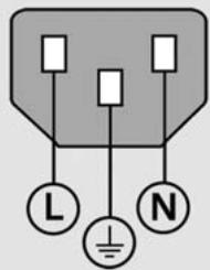
L: Line voltage (brown)
N: Neutral (blue)
Earth ground (yellow/green)

Danger of electrical shock!
- Do not open the enclosure
- Never use 3-wire to 2-wire adapters or allow the ground connection to the ND 1100 to be interrupted or disconnected.

Caution
Changes to the power cable may be made only by an electrical technician.

Caution
Do not connect encoders or other equipment to the ND 1100 when the power is on.
Safety Considerations
General accepted safety precautions must be followed when operating the ND 1100. Failure to observe these precautions could result in damage to the equipment, or injury to personnel. It is understood that safety rules within individual companies vary. If a conflict exists between the material contained in this guide or the and the rules of a company using this system, the more stringent rules should take precedence.
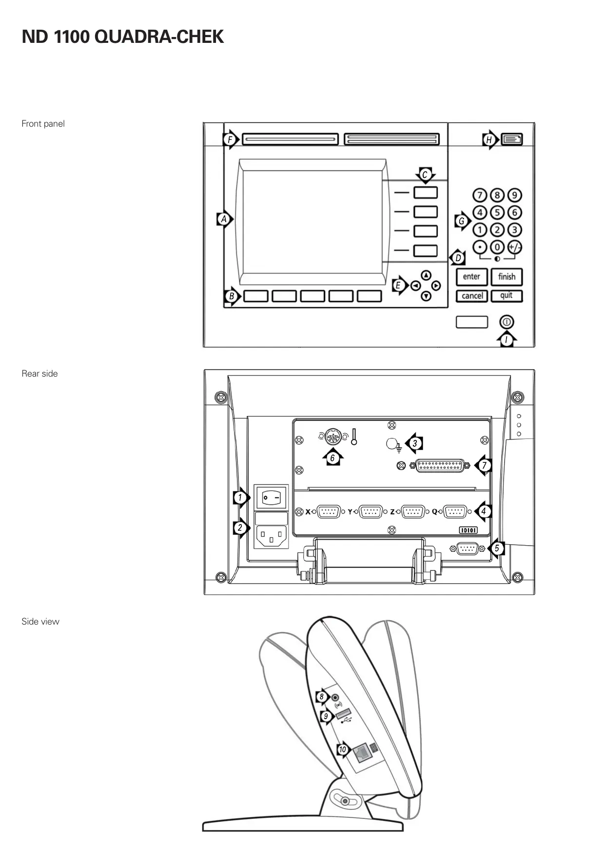
Controls and Displays
| A | LCD screen |
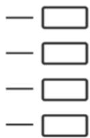
| B | Soft keys: Change to support functions |
| C | Axis keys: Zero or preset datum |
| D | Command keys: Control measurement |
| E | Arrow cursor keys: Menu navigation |
| F | Fast track keys: Programmable for frequently used functions |
| G | Numeric keypad: Enter numeric data |
| H | Send key: Transmit measurement data to PC, USB printer or USB drive |
| I | LCD on/off key: Turn LCD on or off, clear data, datum and skew alignments |
Connections rear side
| 1 | Power switch |
| 2 | Power connection with fuse |
| 3 | Ground (protective ground) |
| 4 | Encoder inputs, X, Y, Z, Q axis for linear and rotary encoders. Interface specified at the time of purchase. |
| 5 | RS-232-C interface for PC connection. RS-232 cable must not include crossovers. |
| 6 | Touch probe connector (optional) |
| 7 | Unused |
Connections side view
| 8 | Audio out, for 3,5 mm headphone /speaker jack, monaural, 8 Ohm |
| 9 | USB type A interface for printer or data storage |
| 10 | Remote accessory interface RJ-45 for optional foot switch or keypad accessory. Two optional remote accessories can be used simultaneously using an RJ-45 splitter. |
Very important
Please note
For your information
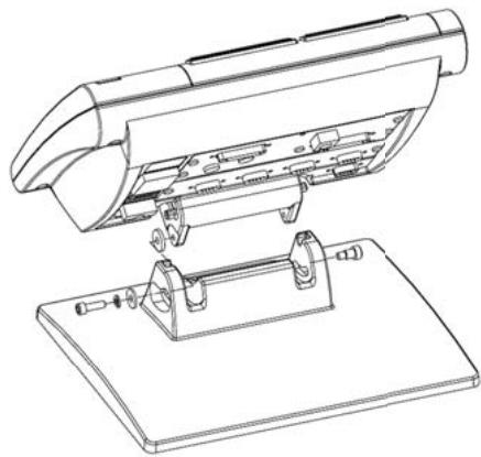
Mounting
The ND 1100 is secured to the swivel slots of the mounting stand or arm mount by a shoulder screw, a cap screw mount is shown and associated washers.
Initial power up
- Press the POWER SWITCH to power the ND 1100. The startup screen is displayed.
- Press the FINISH key to display the current axis positions on the DRO screen.
ND 1100
Software setup
The operating parameters of the ND 1100 must be configured prior to using it for the first time, and any time measurement, reporting or communication requirements change.
Settings will be retained until:
- The data-backup battery is changed
- The data and settings are cleared
- Software upgrades are performed

Caution
Setup parameters control the operation of the ND 1100 and are password-protected. Only qualified personnel should be given password access to setup screens.
1. Access setup menu
Press the MENU key and then press the SETUP soft key. The setup menu is displayed.
2. Select the language
Highlight the desired language field press the YES soft key and then press the ENTER key.
| About | mm | 1 | ||
| About | English | Yes | ||
| Display | François | No | ||
| Encoders | Deutsch | No | ||
| Hot Keys | Espanol | No | ||
| Italiano | No | |||
| Ports | Portugues | No | ||
| Supervisor | v2.15 | |||
| Squareness | (C)2000-2009 | Heidenhain | ||
| LEC | XY | |||
| SLEC | BL 3.00 SN: 123456 | |||
3. Enter Password
- Use the ARROW CURSOR keys to navigate to the SUPERVISOR setup screen.
- Highlight the PASSWORD field, enter the password and then press the ENTER key.
- Enable STARTUP ZERO if a machine zero will be used for SLEC error correction.
| Supervisor | mm | L1 | ||
| About Display Encoders Hot Keys Print Ports Supervisor Squareness LEC SLEC | Password Startup Zero No | |||
4. Encoder setup
- Use the ARROW CURSOR keys to navigate to the ENCODERS setup screen.
- Select an axis and enter the required encoder parameters
- Repeat setup for all axes.
5. Touch probe printing (optional)
When touch probes are used, positions can be printed upon probe contact.
- Use the ARROW CURSOR keys to navigate to the PRINT setup screen.
- Enter the desired edge detection parameters for printing axis position when the probe makes contact.
6. Calibrate stage squareness
- Align the squareness calibration artifact to the reference axis.
- Press the MENU soft key, press the SETUP soft key and then navigate to the Squareness screen.
- Choose a MASTER AXIS, enter the calibration artifact ANGLE, and press the TEACH soft key.
- Follow instructions on the screen.
7. Error correction
Linear and segmented linear error correction methods can be used to compensate for encoder and machine errors. Refer to the ND 1100 User Guide for instructions.
8. Measurement scaling
Linear measurement scaling can be applied when measuring parts that expand or shrink.
- Press the MENU soft key, press the SETUP soft key and then navigate to the SCALE FACTOR screen.
- Enter the desired MULTIPLIER, highlight the ACTIVE field and press the YES soft key to enable scaling.
9. Display formatting
- Press the MENU soft key, press the SETUP soft key and then navigate to the DISPLAY SCREEN.
- Enter the desired display resolutions and other parameters.

Note:
Many more setup functions are available beyond the minimum parameters discussed here. Refer to the ND 1100 User Guide for detailed instructions.
Preparing to probe position
1. Power up the ND 1100
- Check connections to the ND 1100.
- Press the POWER SWITCH to power the ND 1100. Then press the FINISH key to display the DRO screen.
2. Find machine zero (optional)
Move the stage to cross reference marks or find hard stops if your system was set up to establish machine zero at startup.

Note:
A repeatable machine zero is required when SLEC error correction is used. Refer to the User's Guide for detailed information.
3. Select a unit of measure
Press the IN/MM soft key to toggle between inches and mm.
4. Select a datum
Press the ABS/INC soft key to toggle between absolute and incremental datum.
Creating a datum
A current probe position can be zeroed or preset to a value and then used as a datum.
1. Zero a position
Move the crosshairs or touch probe to the desired datum position and press an AXIS key to zero the position on the corresponding axis.
2. Preset a position
- Move the crosshairs or touch probe to the desired datum position and press the PRESET soft key.
- Press the Axis key corresponding to the axis to be preset.
- Enter a preset value and press the ENTER key.
Probing a position
Position is probed with crosshairs or with a touch probe.
1. Probing with crosshairs
Move the stage to position the crosshairs over the desired point. The position will be shown on the LCD screen.
2. Probing with touch probe
- Move the touch probe to the desired point. The position will be shown on the LCD screen.
- When PRINT EDGES is enabled in the PRINT setup screen, the position will be printed upon touch probe contact.
Reporting Results
Press the SEND key to print probed positions on a USB printer or send position data to a PC over the RS-232 serial connection. The report format is specified in the PRINT Setup screen.

HEIDENHAIN
92310 Sèvres, France
0141 143000
[FAX] 0141143030
1. Menu "Setup" openen
N: nulovy vodic (modry)
IoiroTOBka K n3MepeHnIO KOOpDnHaTbI
1.BKJIIOUeHne ND 1100
- Поберъп подсоевиненя ND 1100.
ДлгвклоченяND1100ВкночпБыIKLOCHATEЛПNTAHЯ.3aTeM,чTOбblOTOBpa3nTBTekyuHIONo3nIIO,hAKMITEKONKYFINISH.
2.06nylenne (onzna)
IpepeMaTe KOOpDInHaTy Do IpepeceHnIc pepepeHTHO MeTKoI nIIN DO ynpOB,ecNI CnCTema 6blna HacTpoEHa dIy ObHyJEnHnI pni BKJIIOUChENI.

3aMeuHne:
PnNCNoB3OBaHmN CeMentHOIJIHeHNOH N HeINHeHNO KOMNeHCAuINnOngpeHocTei (SLEC n NLEC)HEo6xOdmo IMeTb BOCpOn3BODmyTOky npRB3Kn CTaHka (HyNeByIO TOky).Boone NOdp6Hoe OINcaHme MOKHOHaHTN BpyKObOCTBe NOlb3OBaTeJ.
3.Bb6op edHHniz3MepeHna
Haxmnte Softkey IIOIMbl/MM nIpekeJIIOUeHnMexKdy MmllImetpamN dIOHMAMN.
4.Bb6opTouknpB83K
Haxmnte Softkey ABS/INC nIpeKJIoueHnMexy a6coHOTbIM INHkpeMeHTaNbHbIM pexMMOM pa60Tbl.
3aDaHne TOUKNIpNBra3KIN
Tekuza KoopDunHaTa NIOJKeHnIyPnA MoKET 6bITb ObHyIeHa NINyCTaHOBJIeHa B ONPeDeIeHHOe3NaueHne, KOToPoE MoKET 6bITbNCIOJIb3OBAHO B KaYeCTBe TOKINIPNIB3KN.
1.06HyIeHne 3NaueHnno3n
IpepeMeCTnTe nepeKePcTne nJIn 7yn K JeNaemOn KoOpDnHaTe
TOUKN INPUBRA3KN HAXMNTe KHOJNKy OCN IJNAO6HUYNEHNA03NUCNI COOTBECTBYIOUeONC.

2.BVbOIO3n
- IpepeMeCTIe pepeKpeCTne nJIn UyN K JeJaEMoK KoOpDnHaTe TOHKn PnpBra3Kn N HaxMnTe Softkey 3AaATb.
Haxmte KhoNky Oci,Дя KOTOpoi Bby XOTTe BBCTn IO3NUIO. - BBeIe 3NaueHne nO3nIu n HaxMITE ENTER.
I3mepenHe ToKn
KoOpDInHaTy TOnkIMoXHO m3Mepntb C nOMOuBHO nepeKePcTeTn IJIN uyna.
1.Измерени сnomоью nepekepectna
IpeMeCTIe Ocb TaK, YTObI IpeKePcTne HaxOINIOCb HaI TOKoI KacAHn. KoOpDInHata ToCkN bYdEt OTo6paKeHa Na 3KpaHe.
Isletime almadan once
Elektrik baglantisi
Sebeke gerilimi: 100 V~ ila 240 V~
(% -15il% +10)
Sebeke frekansi: 43 ila 63 Hz
Sebeke sigortasi: T1600 mA, 250 V
5 × 20 ~mm
Technical support FAX +49 8669 32-1000
Measuring systems ⑥ +49 8669 31-3104
E-mail: service.ms-support@heidenhain.de
TNC support +49 8669 31-3101
E-mail: service.nc-support@heidenhain.de
NC programming +49 8669 31-3103
E-mail: service.nc-pgm@heidenhain.de
PLC programming +49 8669 31-3102
E-mail: service.plc@heidenhain.de
Lathe controls +49 8669 31-3105
E-mail: service.lathe-support@heidenhain.de
www.heidenhain.de
For complete and further addresses see www.heidenhain.de
B1653AOX Villa Ballester, Argentina
www.heidenhain.com.ar
AU FCR Motion Technology Pty. Ltd
Laverton North 3026, Australia
E-mail: vicsales@fcrmotion.com
BA Bosnia and Herzegovina SL
BE HEIDENHAIN NV/SA
1760 Roosdaal, Belgium
www.heidenhain.be
BG ESD Bulgaria
Sofia 1172, Bulgaria
www.esd.bg
BR DIADUR Industria e Comercio Ltda.
04763-070 - São Paulo - SP, Brazil
www.heidenhain.com.br
BY Belarus
50354 Huerth, Germany
www.gertner.biz
CA HEIDENHAIN CORPORATION
Mississauga, OntarioL5T2N2, Canada
www.heidenhain.com
Beijing 101312, China
102 00 Praha 10, Czech Republic
www.heidenhain.cz
DK TPTEKNIKA/S
2670 Greve, Denmark
www.tp-gruppen.dk
ES FARRESA ELECTRONICA S.A.
08028 Barcelona, Spain
www.farresa.es
FI HEIDENHAIN Scandinavia AB
02770 Espoo, Finland
www.heidenhain.fi
FR HEIDENHAIN FRANCE sarl
92310 Sèvres, France
www.heidenhain.fr
GB HEIDENHAIN (G.B.) Limited
Burgess Hill RH15 9RD, United Kingdom
www.heidenhain.co.uk
GR MB Milionis Vassilis
17341 Athens, Greece
www.heidenhain.gr
HK HEIDENHAIN
Kowloon, Hong Kong
E-mail: service@heidenhain.com.hk
HR Croatia SL
India Private Limited
Chennai-600 031,India
www.heidenhain.in
IT HEIDENHAIN ITALIANA S.r.l.
20128 Milano, Italy
www.heidenhain.it
JP HEIDENHAIN K.K.
Tokyo 194-0215, Japan
www.heidenhain.co.jp
KR HEIDENHAIN Korea LTD.
Gasan-Dong, Seoul, Korea 153-782
www.heidenhain.co.kr
ME Montenegro SL
MK Macedonia BG
MX HEIDENHAIN CORPORATION MEXICO
20235 Aguascalientes, Ags., Mexico
E-mail: info@heidenhain.com
MY ISOSERVE Sdn. Bhd
56100 Kuala Lumpur, Malaysia
E-mail: isoserve@po.jaring.my
7300 Orkanger, Norway
www.heidenhain.no
PH Machinebanks' Corporation
Quezon City, Philippines 1113
E-mail: info@machinebanks.com
PL APS
02-489 Warszawa, Poland
www.apserwis.com.pl
PT FARRESA ELECTRONICA, LDA.
4470 - 177 Maia, Portugal
www.farresa.pt
125315 Moscow, Russia
www.heidenhain.ru
SE HEIDENHAIN Scandinavia AB
12739 Skärholmen, Sweden
www.heidenhain.se
SG HEIDENHAIN PACIFIC PTE LTD.
Singapore 408593
www.heidenhain.com.sg
SK KOPRETINATN s.r.o.
91101 Trencin, Slovakia
www.kopretina.sk
Bangkok 10250, Thailand
www.heidenhain.co.th
TR T&M Muhendislik San. ve Tic. LTD. STI.
34728 Umraniye-Istanbul, Turkey
www.heidenhain.com.tr
TW HEIDENHAIN Co., Ltd.
Taichung 40768, Taiwan R.O.C.
VN AMS Advanced Manufacturing
Solutions Pte Ltd
HCM City, Viet Nam
E-mail: davidgoh@amsvn.com
ZA MAFEMA SALES SERVICES C.C.
Midrand 1685, South Africa
www.heidenhain.co.za