USER MANUAL IR 5000 CAMPINGAZ
natural_image
Abstract black-and-white geometric pattern with diagonal lines and a diamond shape (no text or symbols)
FR
MODE D'EMPLOI
GB
INSTRUCTIONS FOR USE
NL
GEBRUIKSAANWIJZING
DE
GEBRAUCHSANLEITUNG
IT
ISTRUZIONI PER L'USO
ES
INSTRUCCIONES DE EMPLEO
CZ
NÁVOD K POUŽITÍ
HR
UPUTA ZA KORIŠTENJE
HU
HASZNÁLATI ÚTMUTATÓ
PT
MODO DE EMPREGO
SE
BRUKSANVISNING
DK
BETJENINGSVEJLEDNING
NO
BRUKSANVISNING
FI
KÄYTTÖOHJE
PL
INSTRUKCJA OBS£UGI
SI
PRIROÈNIK ZA UPORABO
SK
NÁVOD NA POUŽITIE
natural_image
Exterior view of a portable gasifier unit with ventilation grilles and wheels (no visible text or symbols)
IR 5000 IR 5000 TURBO
CAMPING GAZ ITALIA VIA CA' NOVA II, 25010 CENTENARO DI LONATO (BRESCIA) ITALIA
Réf. 071004 - 04/05 - A

IR 5000
IR 5000 TURBO (230 V - 50 Hz)
(18 W - 188 mA)
CONDITIONS D'APPLICATION DE LA GARANTIE
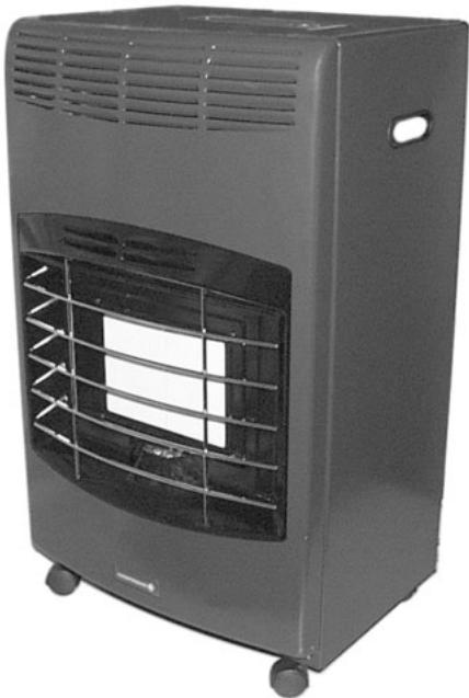
Thank you for choosing this Campingaz® infrared heater.
This operating handbook deals with infrared heater:
IR 5000 - IR 5000 Turbo
A - GENERAL SAFETY INSTRUCTIONS
- This appliance must be used and serviced in accordance with the regulations and standards in force.
- Please read this handbook before using your appliance.
- This appliance should not be used in building or tower flats, in basements, bathrooms or bedrooms.
- Only use this appliance in a well ventilated room.
- This appliance should not be used in leisure vehicles such as caravans and camping-cars.
This appliance should not be installed in the vicinity of walls, pieces of furniture, hangings, curtains, bedding items and other inflammable materials. To prevent fire hazards, it is strictly forbidden to cover the appliance.
- This appliance should always be directed to the centre of the room.
Do not use your heater less than 50 cm from a wall or combustible object.
B - ASSEMBLING THE WHEELS
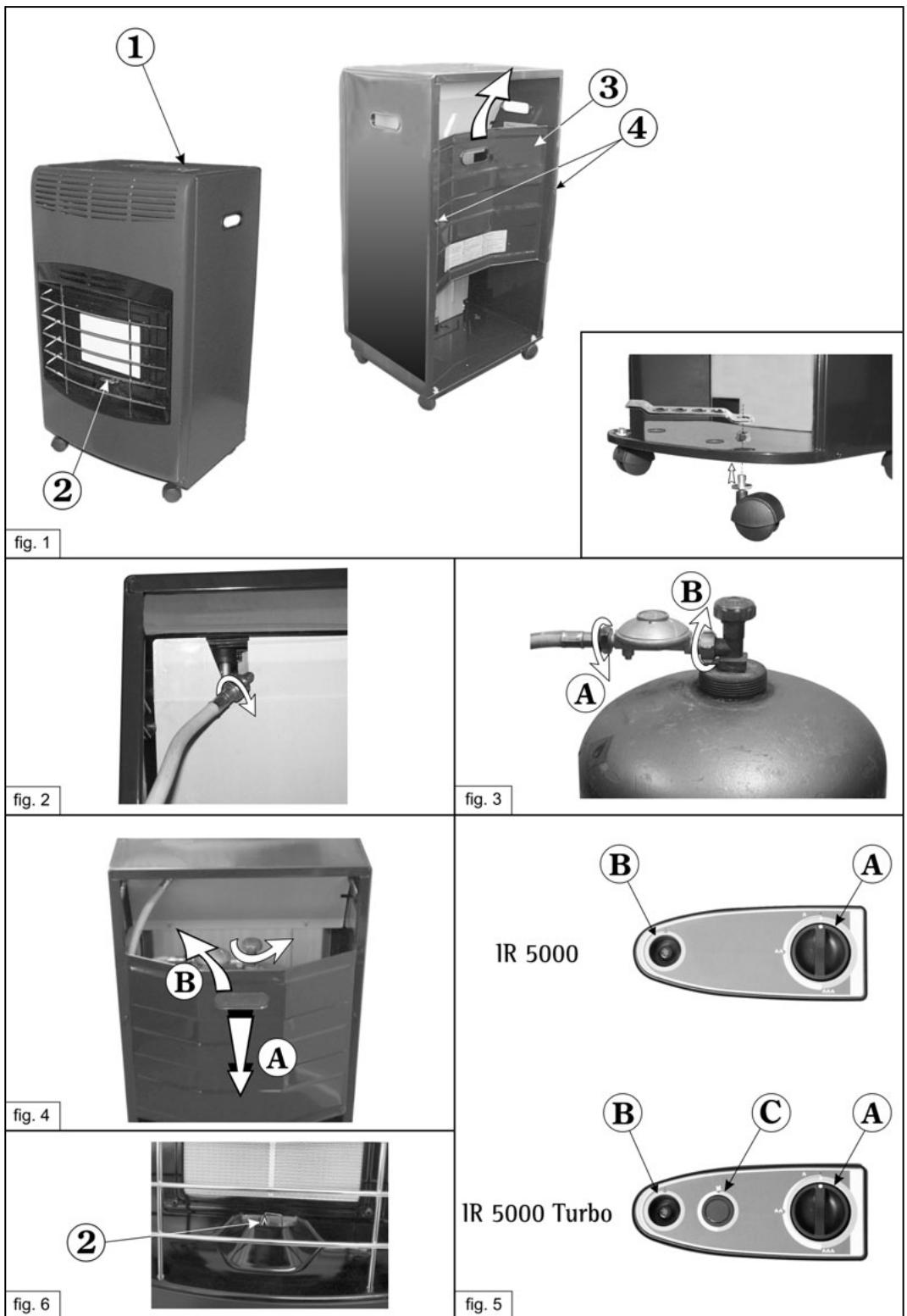
Mount the four wheels on the bottom of the heater using the spanner provided for this purpose. (see Fig. 1)
C - SETTING TO SERVICE
IMPORTANT
This operating handbook is intended for enabling you to correctly and safely use your Campingaz® appliance. Refer to the handbook to familiarise yourself with the appliance before connecting the gas bottle.
Comply with this operating handbook instructions.
This appliance must be connected using a pressure reducing valve and a hose. Call your vendor.
Non conformance with these instructions may be dangerous for the user and his environment.
Permanently keep this handbook in a safe place so as to refer to it when needed.
This appliance is preset in factory to operate with butane using appropriate pressure reducing valve and hose. In operation, this appliance must be held away from inflammable materials.
Do not use a leaking, malfunctioning or damaged appliance. Return it to your vendor who will give you the address of the nearest dealer.
This appliance should never be modified nor used in applications for which it is not designed.
C - 1 - Ventilating the room:
This appliance is an infrared combustion heater designed to be used in adequately ventilated premises.
A suitable ventilation makes it possible to exhaust combustion residues and renew the combustion air.
The appliance should not be installed in a room the volume of which is less than 82 m ^3 for living-rooms and 41 m ^3 for other rooms.
Air renewal ventilation area should not be less than 103 cm^2 evenly distributed between room upper and lower levels.
A safety device will shut off the gas, thus extinguishing the appliance if normal ventilation conditions are not met.
C - 2 - Gas bottle and pressure reducing valve:
This appliance is designed to operate with 11 Kg to 15 Kg Butane or Propane gas bottles fitted with an adequate pressure reducing valve (See Gas and operating pressures page 3).
Only use the type of gas stipulated by the manufacturer. In France, it is strictly forbidden to use another gas type than Butane.
To install the pressure reducing valve, follow pressure reducing valve operating handbook instructions.
To connect or replace the bottle, always operate in a well-ventilated place, never in presence of a flame, spark or heat source.
C - 3 - Gas hose:
France:
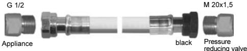
The appliance must be used with a hose fitted with a G 1/2 threaded nut to be screwed to the appliance and an M 20x1.5 threaded nut to be screwed to the pressure reducing valve (XP D 36-112 Standard).
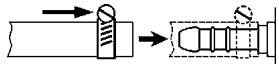
The hose shall be 0.50 m long. It shall be replaced if it appears to be damaged or cracked. Do not pull or twist the hose. Keep it away from parts that are likely to get heated.
Hose installation, G 1/2 and M 20x1.5 nuts (XP D 36-112 Standard) (See Fig. 2 and 3):
- Check tightness in compliance with indications of paragraph D-2.
Switzerland, Germany, Austria:
This appliance must be used with a DIN hose the quality of which shall comply with the use of butane or propane gas.
The hose shall be 0.50 m long. It shall be replaced if it appears to be damaged or cracked. Do not pull or twist the hose. Keep it away from parts that are likely to get heated.
Connecting the hose: to connect the hose to appliance inlet union, firmly but moderately tighten the hose using 2 suitable spanners:
- 14 mm spanner to tighten appliance inlet union.
- 17 mm spanner to screw in hose nut.
Connect the other end to pressure reducing valve outlet union.
- Check tightness in compliance with indications of paragraph D-2.
Other countries:
The appliance is fitted with a ringed end-piece. It must be used with a hose the quality of which shall comply with the use of butane or propane gas and with the national regulations in force (BS, UNI, UNE, etc....).
The hose shall be 0.50 m long. It shall be replaced if it appears to be damaged or cracked. Do not pull or twist the hose. Keep it away from parts that are likely to get heated.
- Check tightness in compliance with indications of paragraph D-2.
D - CONNECTING THE GAS BOTTLE
If an empty bottle is in place, read paragraph F-"Removing or replacing gas bottle".
To install or remove a gas bottle, always operate in a well-ventilated place and never in presence of a flame, spark or heat source (cigarette, electric appliance, etc.).
- Open appliance rear plate (fig. 1 item 3).
Note: if the appliance is new, loosen screws (4) by a quarter turn, lift and remove rear plate (3).
D - 1 - Installing gas bottle:
- Position the gas bottle on the floor behind the appliance.
- Check whether bottle cock and/or pressure reducing valve handle is in "closed" position.
- Screw in or engage pressure reducing valve to gas bottle or gas bottle cock (fig. 3 item B).
- Install gas bottle through appliance rear so that the hose does not touch appliance metal panels and is not excessively bent or pinched.
- Check that the hose runs normally and is neither bent nor pulled.
- Install appliance rear plate (fig. 4 item A).
D - 2 - Tightness:
In case of leak, appliance gas supply must be shut down using gas bottle cock and/or pressure reducing valve handle.
Do not carry out leak tests with a flame, use a gas leak detecting liquid.
- Apply gas leak detecting liquid to bottle/pressure reducing valve/hose/appliance unions.
- Open the gas inlet (bottle cock and/or pressure reducing valve handle) (fig. 4).
- If bubbles appear, this means that there are gas leaks.
- To remove the leak, tighten hose nuts and/or hose clamps if any. If a part is defective, have it replaced. The appliance should not be returned to service until the leak is removed.
- Close gas bottle cock.
Important:
In case of gas leak or odour, immediately close bottle cock and/or pressure reducing valve handle. Enhance room ventilation by opening the windows. Ask a specialised technician to check the appliance and proper bottle connection.
A leak test should be carried out at least once a year and whenever the gas bottle is changed.
E - UTILISATION
OPERATING PRECAUTIONS:
DO NOT install the appliance next to a wall, curtains or a sofa or armchair.
DO NOT cover the appliance with clothes or other objects.
DO NOT move the appliance when in operation. The appliance must ALWAYS be directed to the centre of the room.
The appliance must be put in a dry place.
This appliance protecting grid is designed to prevent fire hazards or burns and no part shall be permanently removed.
THE GRID DOES NOT TOTALLY PROTECT YOUNG CHILDREN OR THE DISABLED.
E - 1 - IGNITING THE APPLIANCE:
Note: Gas opening and closing controls are located on gas bottle and/or on pressure reducing valve.
The ignition spark, gas inlet control and power control are operated on the control panel located in the top right-hand corner of the appliance. (fig. 1 item 1) and (fig. 5 items A, B and C)
1- Open bottle cock and/or pressure reducing valve handle and carry out a leak test.
IR 5000 Turbo Version
Plug in the appliance.
Caution: The appliance was designed to be supplied with a 230 V 50 Hz voltage. Your installation must be equipped with a grounding connection compliant with electrical systems specifications in force.
- Do not place the heater just below an electric socket.
- Do not use the heater near a bath, shower or swimming pool.
2- Set handle (A) to position (●) and press the handle for 10 seconds to allow the gas to reach the pilot burner (fig. 5).
3- Fully press several times the LH button marked with a stylised star ()(B) for lighting up the flame, while holding control button (A) depressed for 10 seconds. The thermocouple is activated and the safety valve does not cut off gas feed.
Release control button (A)
4- Check whether the appliance did light up. If not, repeat the procedure from step 2.
Note: Some air may be trapped in the gas line. This will prevent the appliance from lighting up during the first attempt. In this case, it is necessary to repeat the ignition procedure several times until the safety pilot burner lights up.
During appliance operation, the safety pilot burner must remain permanently lit in order to ensure correct operation of the atmosphere analyser.
During the first setting to service, operate the appliance at maximum power for at least 15 minutes in order to eliminate the typical new appliance smell due to the presence of protecting substances applied to the component parts. Ventilate the room during this operation.
E - 2 - POWER CONTROL (FIG. 5):
Your appliance is equipped with a setting handle which makes it possible to adjust the temperature radiated by the infrared panel depending on the temperature desired in the room.
a) IR 5000 and IR 5000 Turbo Versions
- Adjust the power by placing the mark on the lever between ( ) and ( ) (3 positions, see Fig. 5 - IR 5000 - and - IR 5000 Turbo - reference A)
b) Exclusive to IR 5000 Turbo Version
After lighting up your appliance in compliance with the indications of paragraph E-1, you can increase its heating performance by means of the "Turbo" function.
The "Turbo" function provides for fast and even heating of the room because it uses a tangential ventilation to propel the hot air flow out of the appliance.
The "Turbo" function is turned on / off by pressing the red button (fig. 5 - CR 5000 Turbo - item C).
CAUTION:
The appliance was designed to be supplied with a 230 V 50 Hz voltage.
Your installation must be equipped with a grounding connection compliant with electrical systems specifications in force.
E - 3 - SHUTTING DOWN THE APPLIANCE:
- close bottle cock and/or gas pressure reducing valve handle.
THIS APPLIANCE IS EQUIPPED WITH AN ATMOSPHERE ANALYSER DEVICE WHICH AUTOMATICALLY TURNS OFF THE APPLIANCE SHOULD THE ROOM CONTAIN TOO HIGH A CARBON DIOXIDE PERCENTAGE (CO _2 ).
IN THIS CASE, THOROUGHLY VENTILATE THE ROOM, OTHERWISE THE APPLIANCE WILL NOT RELIGHT.
F - REMOVING OR REPLACING THE GAS BOTTLE
- Check that gas bottle cock and/or pressure reducing valve handle is in the closed position.
- Open appliance rear plate (fig. 4 item B) and remove the bottle from its housing, taking care not to pull or bend the hose.
- Disconnect pressure reducing valve from gas bottle.
- Install the new gas bottle and carry out a leak test as described under paragraphs D-1 and D-2.
G - STORAGE - SERVICING
1) Appliance
When it is not used, the appliance should remain open and be stored in a dust-free place.
- Remove stains with soapy water, when the appliance is cold. Wipe off with a cloth.
- Do not use abrasives which might damage the paint-work.
- For heavy repairs, please call your vendor.
- The appliance must be periodically checked, more particularly concerning condition of the connecting hose.
2) Hose between the pressure reducing valve and the appliance
- Periodically check hose for condition and replace it if it displays ageing signs or cracks.
- The hose must be replaced by a new one of same length and equivalent quality.
- The hose must be replaced in compliance with the above-mentioned periodicity for the respective countries.
- In France, if the expiry date printed on the hose is reached, it must be replaced by a hose compliant with the XP D 36-112 Standard.
- Comply with installation indications provided with these new assemblies to be 0.50 m long, and with the procedure described under paragraph C - 2.
- If your appliance is to remain unused for a long period, disconnect gas bottle.
3) Electric supply cable (IR 5000 Turbo model)
- All damaged cables must be replaced by the manufacturer, its after-sales service or a similarly-qualified person, to avoid danger.
Defects / Remedies
| Defects | Probable causes / remedies |
| The burner does not light up | - Poor gas feed- Pressure reducing valve inoperative- Check for gas level in bottle |
| The burner misfires or turns off | - Check for gas level in bottle- Check hose connection- Call technical support |
| Unstable blowing flames | - New bottle. Allow to operate, the defect will disappear- Call technical support |
| The pilot burner does not light up | - Pilot burner clogged- Call technical support. |
WARRANTY APPLICATION TERMS AND CONDITIONS
The product is covered by a total parts and labour warranty for 2 years with effect from the purchase date, excluding return transport charges that should be borne by the consumer. The warranty applies when the delivered product does not conform to the order or is defective, from the moment that the claim is accompanied by proof of purchase date (e.g. invoice, till receipt). The product should be returned carriage paid, complete and assembled, to an authorised after-sales service centre, with the claim describing the nature of the problem. A product for which a claim is being made may be repaired, replaced or reimbursed, in full or partially. The warranty is null and void and does not apply if the damage is caused by (i) incorrect product use or storage, (ii) defective product maintenance or maintenance that fails to comply with the instructions for use, (iii) repair, modification or servicing of the product by unauthorised third parties, (iv) the use of non-original spare parts.
In case of continued difficulty, please contact your local retailer who will give you details of the nearest After Sales Service point, or call the CAMPINGAZ® Customer Service at:
COLEMAN UK PLC - Gordano Gate Wyndham Way - Portishead
BRISTOL BS20 7GG ENGLAND
© 01275 845 024 / Fax: 01275 849 255
WARNING: Due to our policy of continual product development, the company reserves the right to alter or modify this product without prior notice.
Web site: www.campingaz.com
D - TILKOBLING AV GASSBEHOLDEREN
G - OPPBEVARING - VEDLIKEHOLD
1) Apparatet
G - SÄILYTYS - HUOLTO
1) Laite