Uniprodo UNI_POOL_REEL_585 - Washing machine

UNI_POOL_REEL_585 - Washing machine Uniprodo - Free user manual and instructions

Find the device manual for free UNI_POOL_REEL_585 Uniprodo in PDF.

📄 449 pages English EN Download 💬 AI Question 10 questions ⚙️ Specs
Notice Uniprodo UNI_POOL_REEL_585 - page 1
Pick your language and provide your email: we'll send you a specifically translated version.
Product type Pool reel system (solar film roller)
Brand Uniprodo
Model UNI_POOL_REEL_585
Dimensions (side with lever / opposite side) 49,5 / 35,3 x 17 x 509 mm
Weight 5,85 kg
Compatible pool width 1,22 to 6 m
Length of roller tubes 105 cm (7 pieces) + 32 cm (1 piece)
Tube diameter 42 / 37 cm
Maximum load 30,15 kg
Power supply None (manual use)
Main function Rolling up, unrolling and storing the pool solar film
Safety Read the manual carefully before use
Maintenance Clean with a soft cloth, without corrosive products
Storage In a dry and cool place, protected from moisture and sunlight
Repairability Only by the manufacturer's service center with original parts
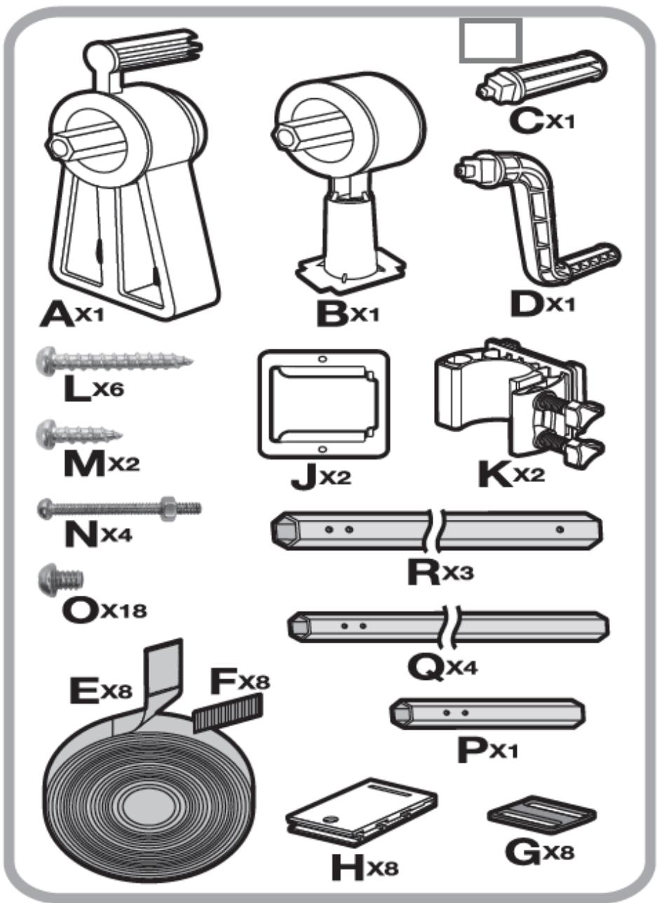
Package contents Supports, rollers, straps, clips, screws, etc. (details in the manual)

Frequently Asked Questions - UNI_POOL_REEL_585 Uniprodo

How to assemble the UNI_POOL_REEL_585 pool reel system?
To assemble the roller, start by attaching the roller supports to the sides of the pool. Use the bases suitable for the edge type (flat or tubular). Connect the roller tubes with a minimum overlap of 20 cm. Attach the Velcro straps to the roller at the indicated intervals. Mount the assembly on the supports and check the stability before use.
What pool width is compatible with this model?
The UNI_POOL_REEL_585 model is compatible with pools with a width between 1,22 m and 6 m. This width corresponds to the total length of the deployable roller.
How to attach the Velcro straps to the solar film?
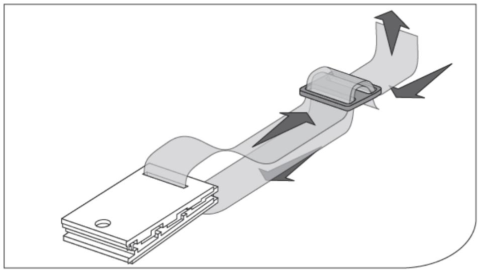
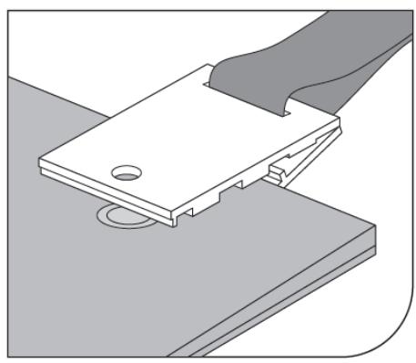
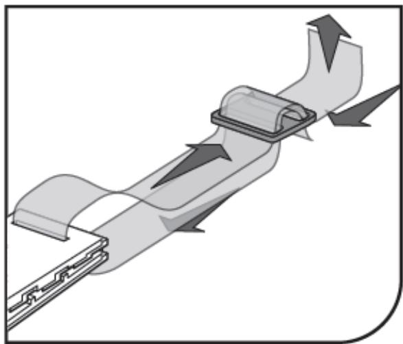
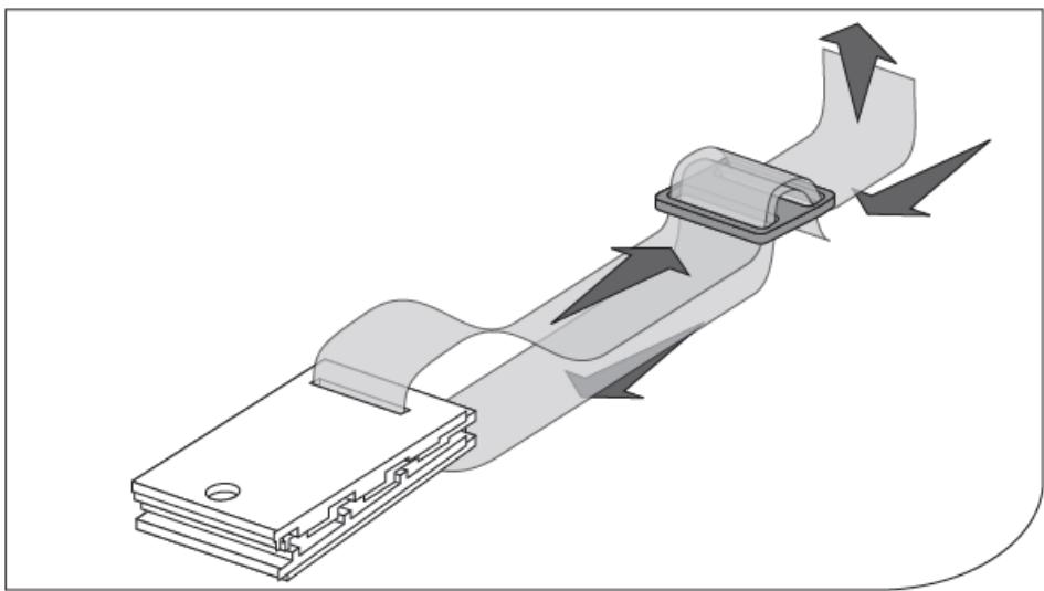
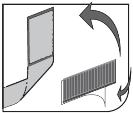
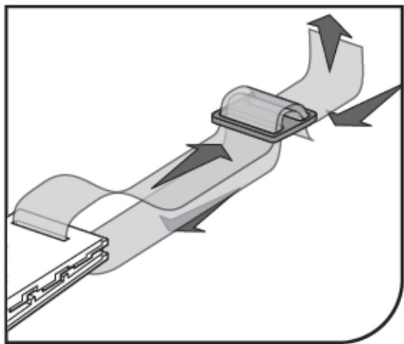
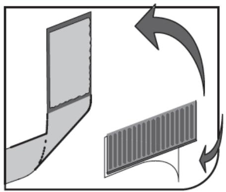
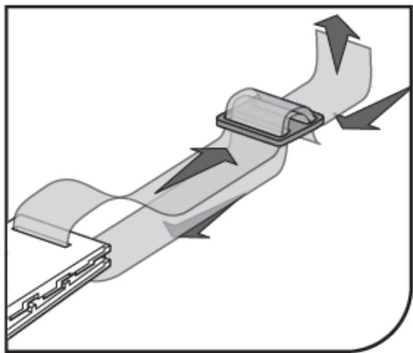
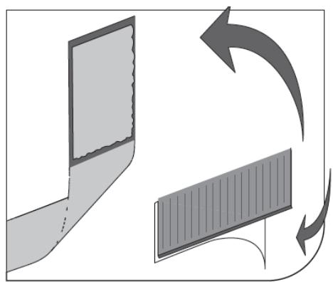
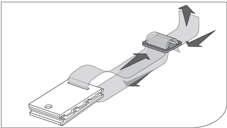
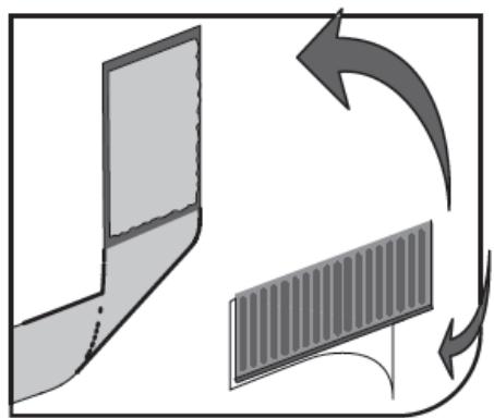
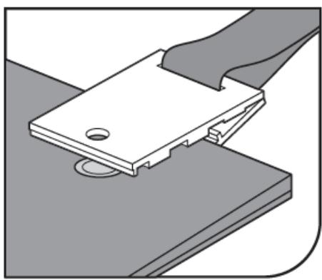
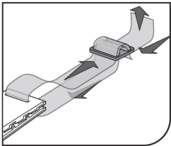
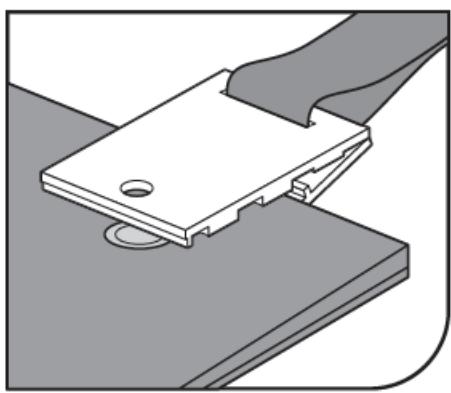
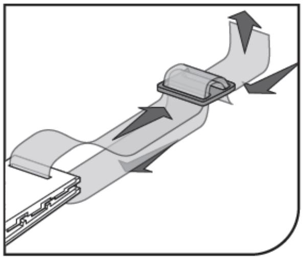
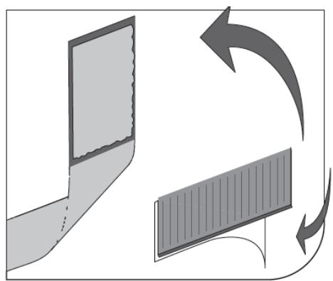
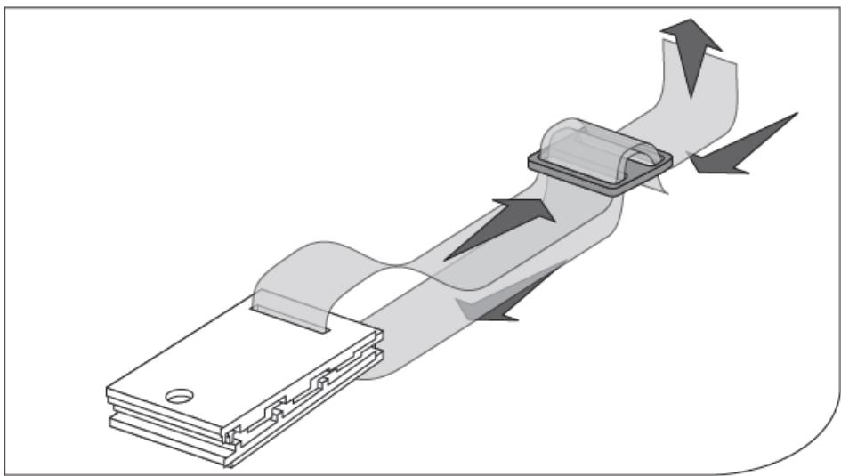
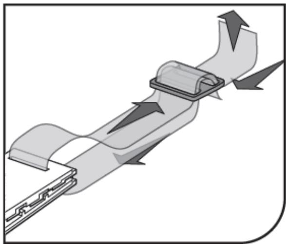
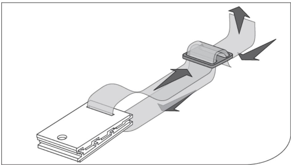
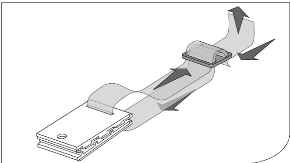
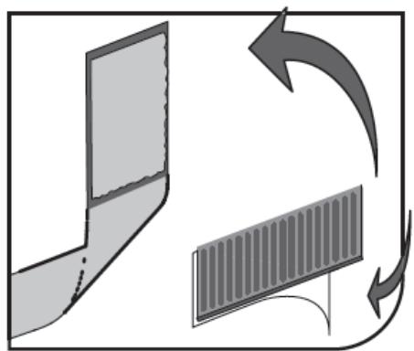
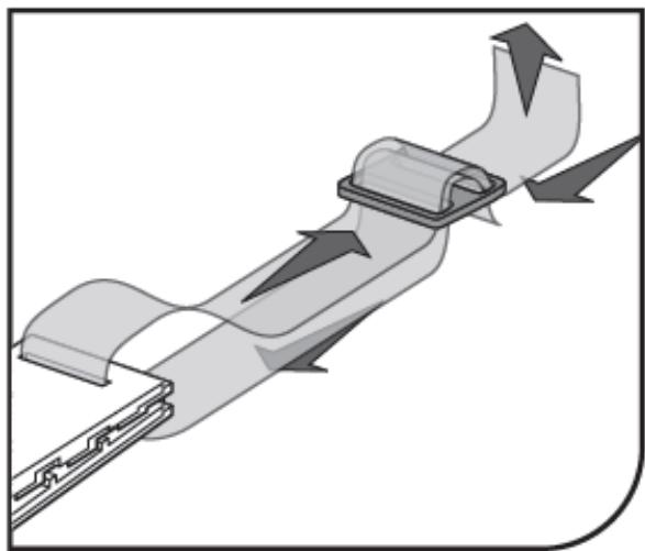
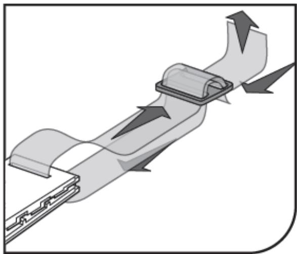
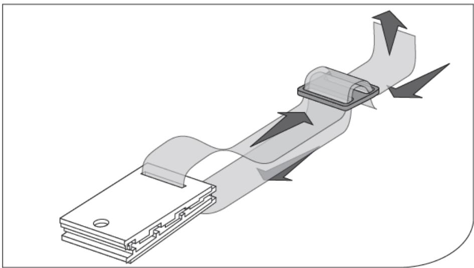
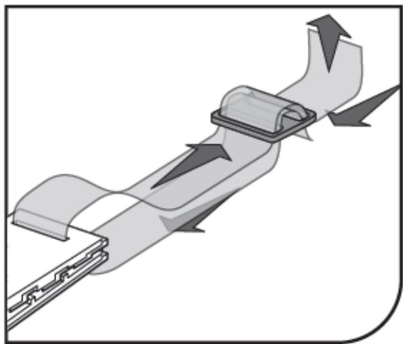
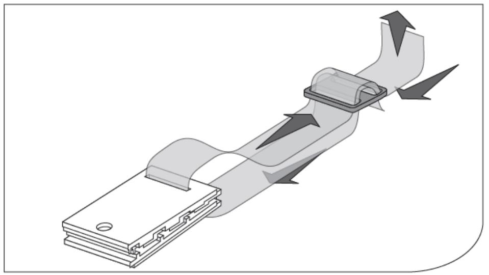
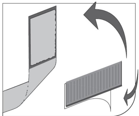
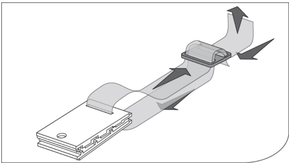
Peel off the male Velcro strip from the strap, remove the adhesive protection, then stick it on the roller perpendicular to its axis. Then mount the clamp and the clip on the strap. Attach the clips to the solar film at the intervals corresponding to the Velcro on the roller.
What safety precautions should I take when using it?
Before any use, read the manual carefully. Never stand on the solar film during rolling or unrolling. Make sure no person or animal is in the pool. Do not use the device if you are tired or under the influence of substances. Check the condition of the device before each use.
How to maintain the pool roller?
Clean the surfaces with a soft cloth and non-corrosive products. Dry all parts after cleaning. Store the device in a dry and cool place, protected from moisture and sunlight. Perform regular checks to detect any damage.
Can I use this device for other types of covers?
The device is specifically designed for rolling and storing the pool solar film. Its use with other types of covers, such as thicker bubble covers, may cause overload or damage. Respect the maximum load of 30,15 kg.
What to do if the film gets stuck during rolling?
If the roller jams, do not use excessive force. Check that the film is correctly positioned and that no obstacle interferes with the movement. Remove the blockage by slightly unrolling the film, then proceed with rolling again.
How to store the system after use in winter?
Disassemble the supports and rollers, clean and dry all parts. Store them in a dry place, protected from frost and moisture. Protect the plastic parts from direct UV rays to prevent deterioration.
Can I repair the device myself in case of damage?
It is imperative not to attempt any repair yourself. Only the manufacturer's service center is authorized to carry out repairs. Use only original spare parts to ensure safety and proper operation.
Is the manual available in other languages?
The manual is mainly available in English and French. To obtain a translation in another language, contact customer service at info@expondo.com. A digital version is also downloadable from the website.

User questions about UNI_POOL_REEL_585 Uniprodo

0 question about this device. Answer the ones you know or ask your own.

Ask a new question about this device

Your email remains private: it is only used to notify you if someone answers your question.

No questions yet. Be the first to ask one.

Download the instructions for your Washing machine in PDF format for free! Find your manual UNI_POOL_REEL_585 - Uniprodo and take your electronic device back in hand. On this page are published all the documents necessary for the use of your device. UNI_POOL_REEL_585 by Uniprodo.

USER MANUAL UNI_POOL_REEL_585 Uniprodo

3.2.2. UNI_POOL_REEL_570

3.2.3. UNI_POOL_REEL_585

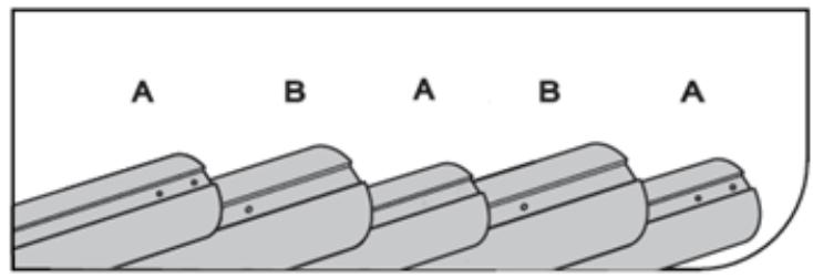
Abb. 2.
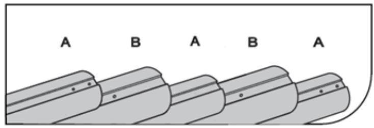
Technical diagram showing exploded view of mechanical components with numbered parts and exploded views

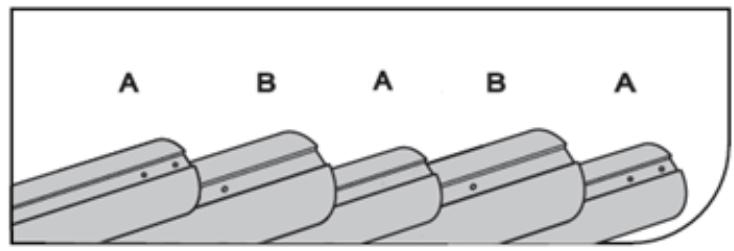
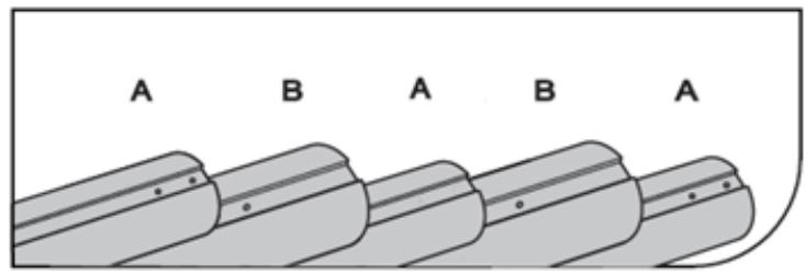
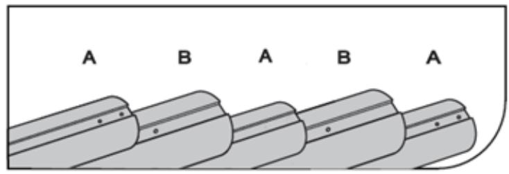
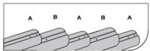
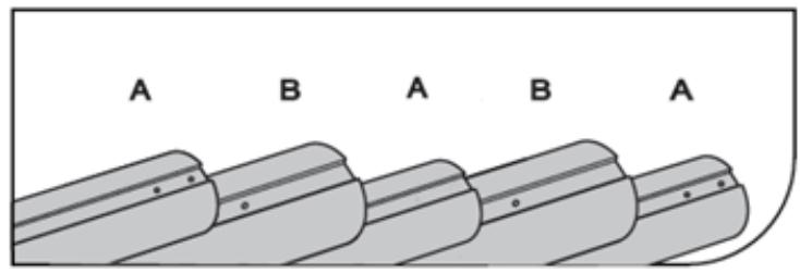
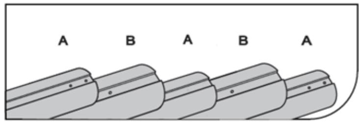
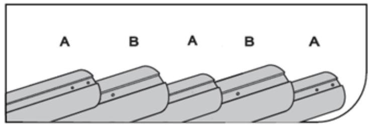
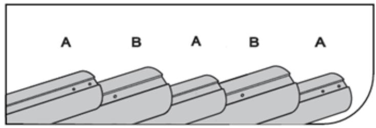
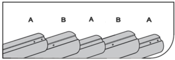
A B A B A

Abb. 3
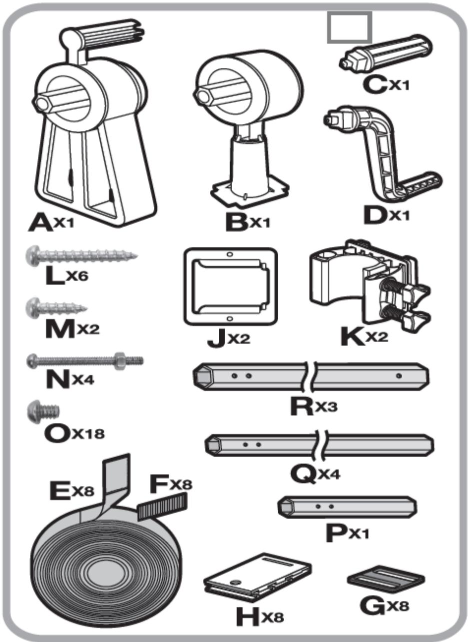
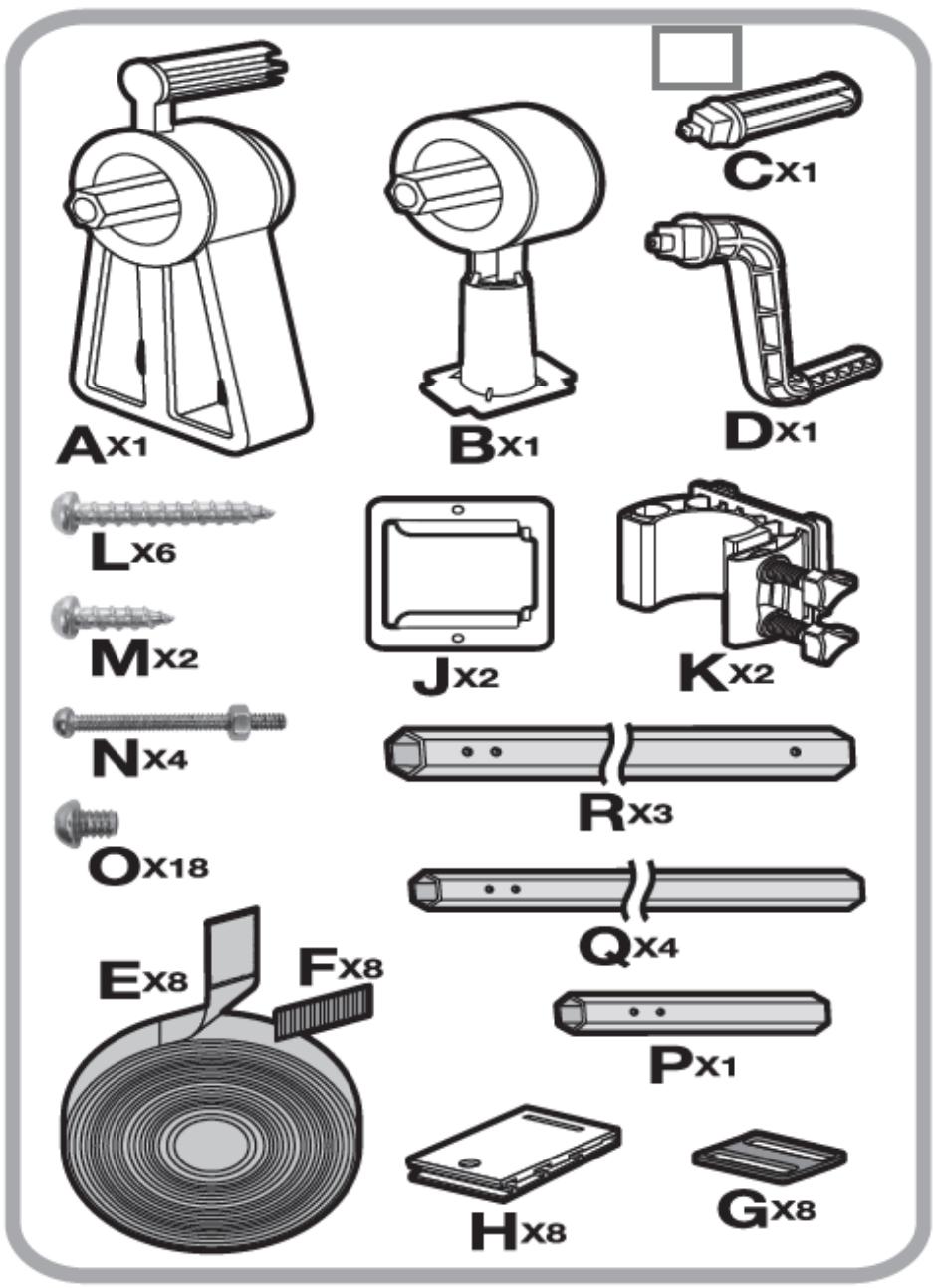
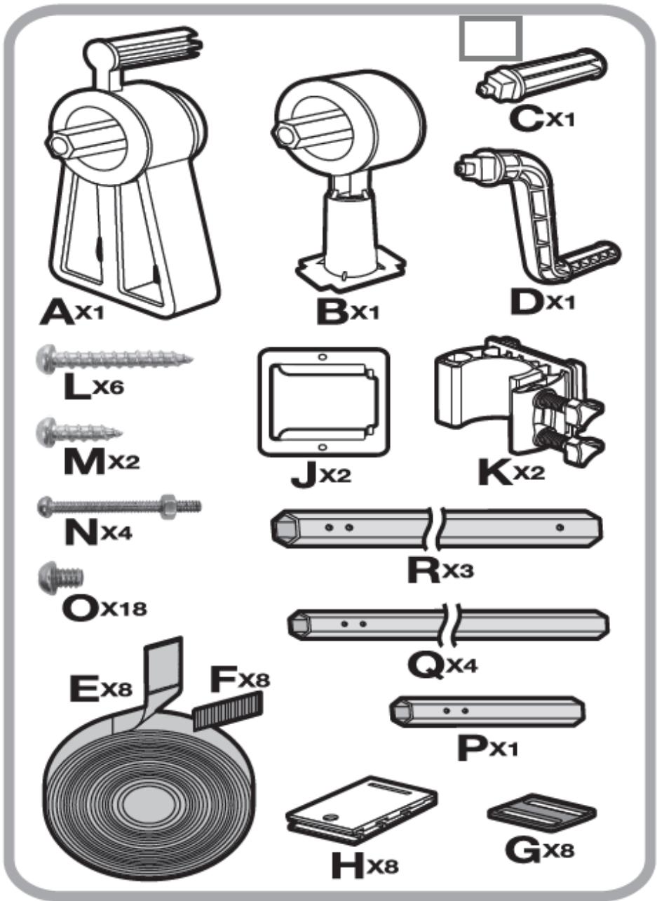
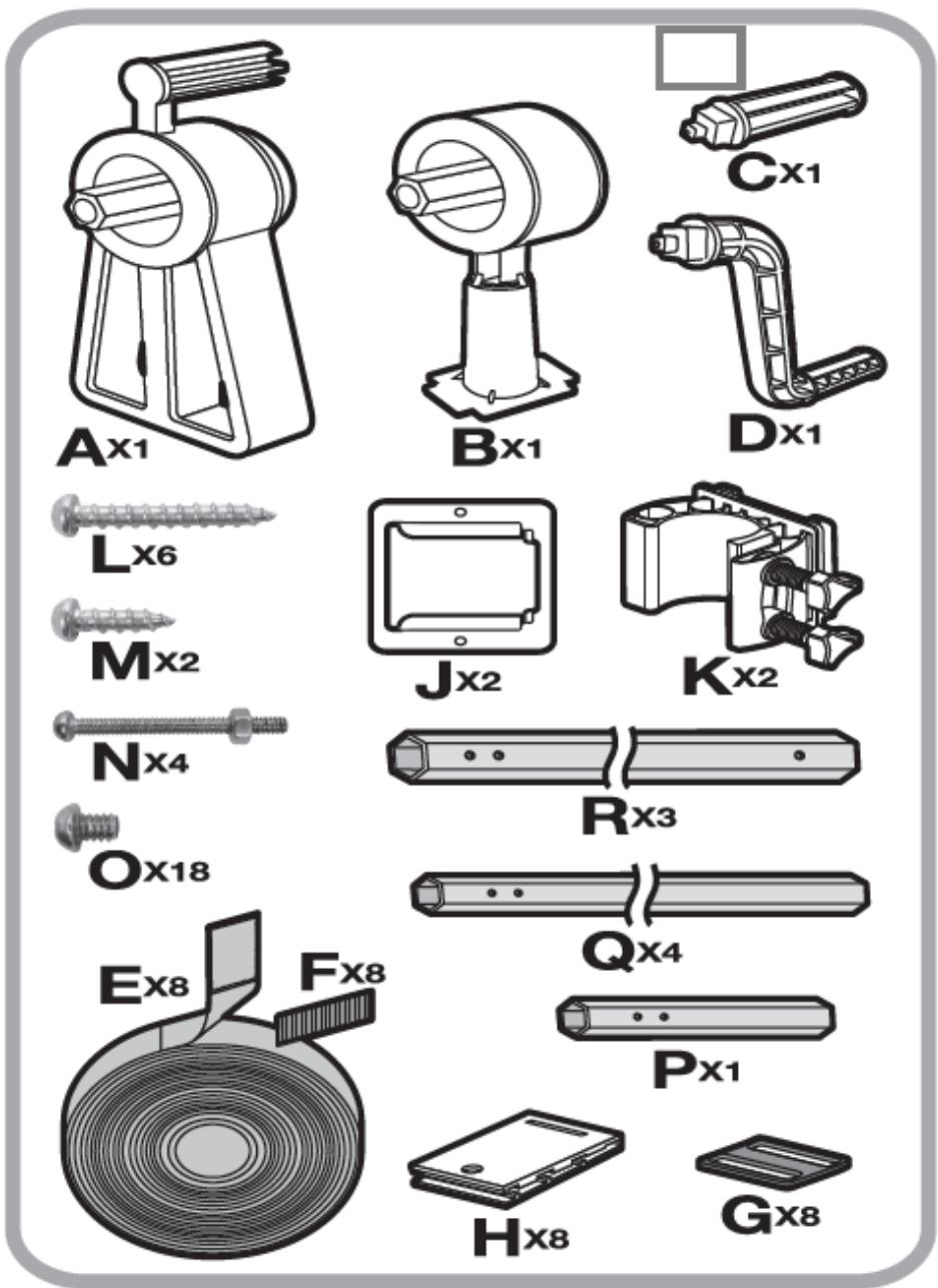
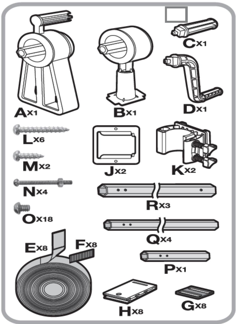
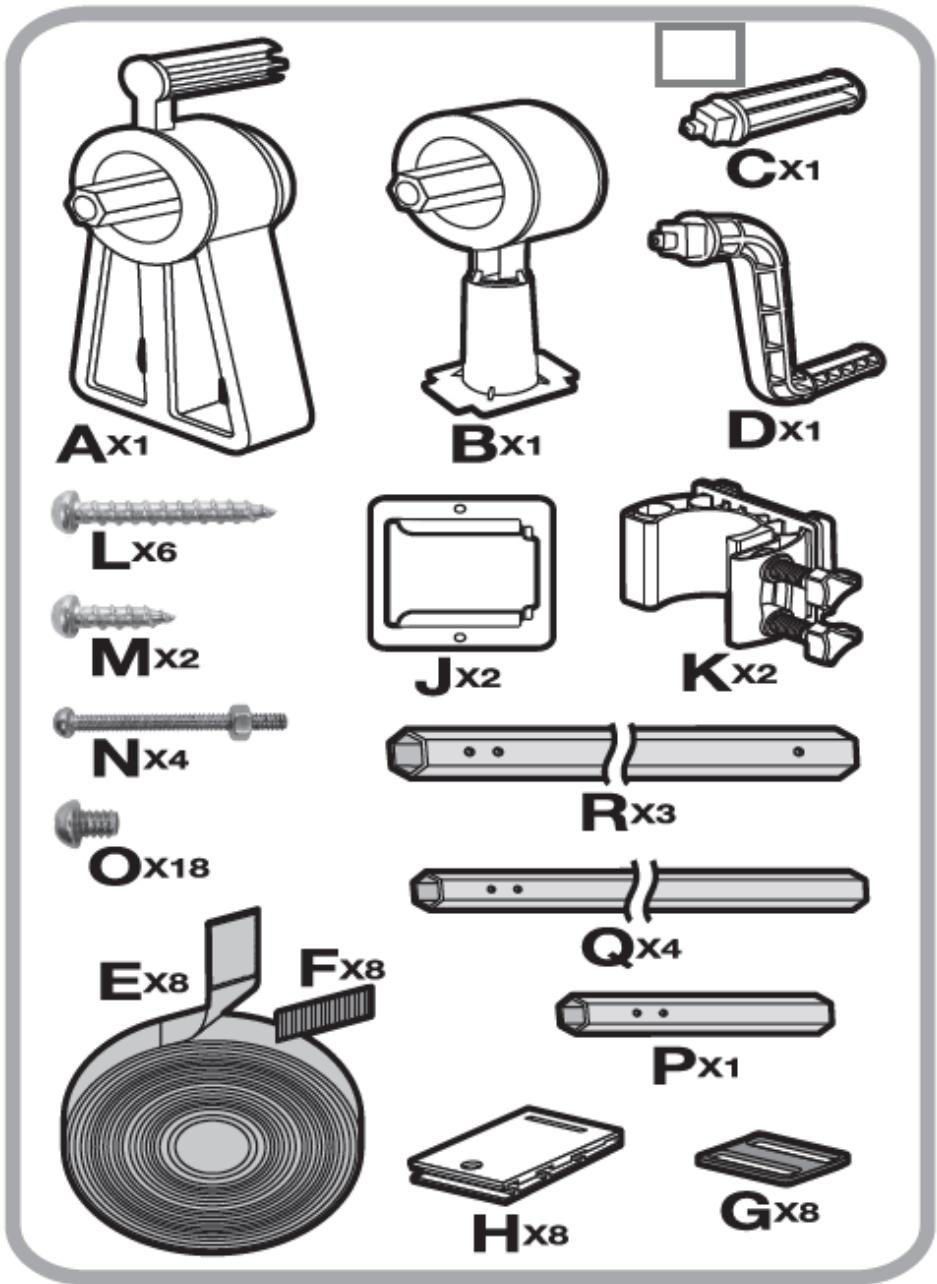
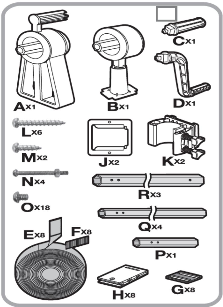
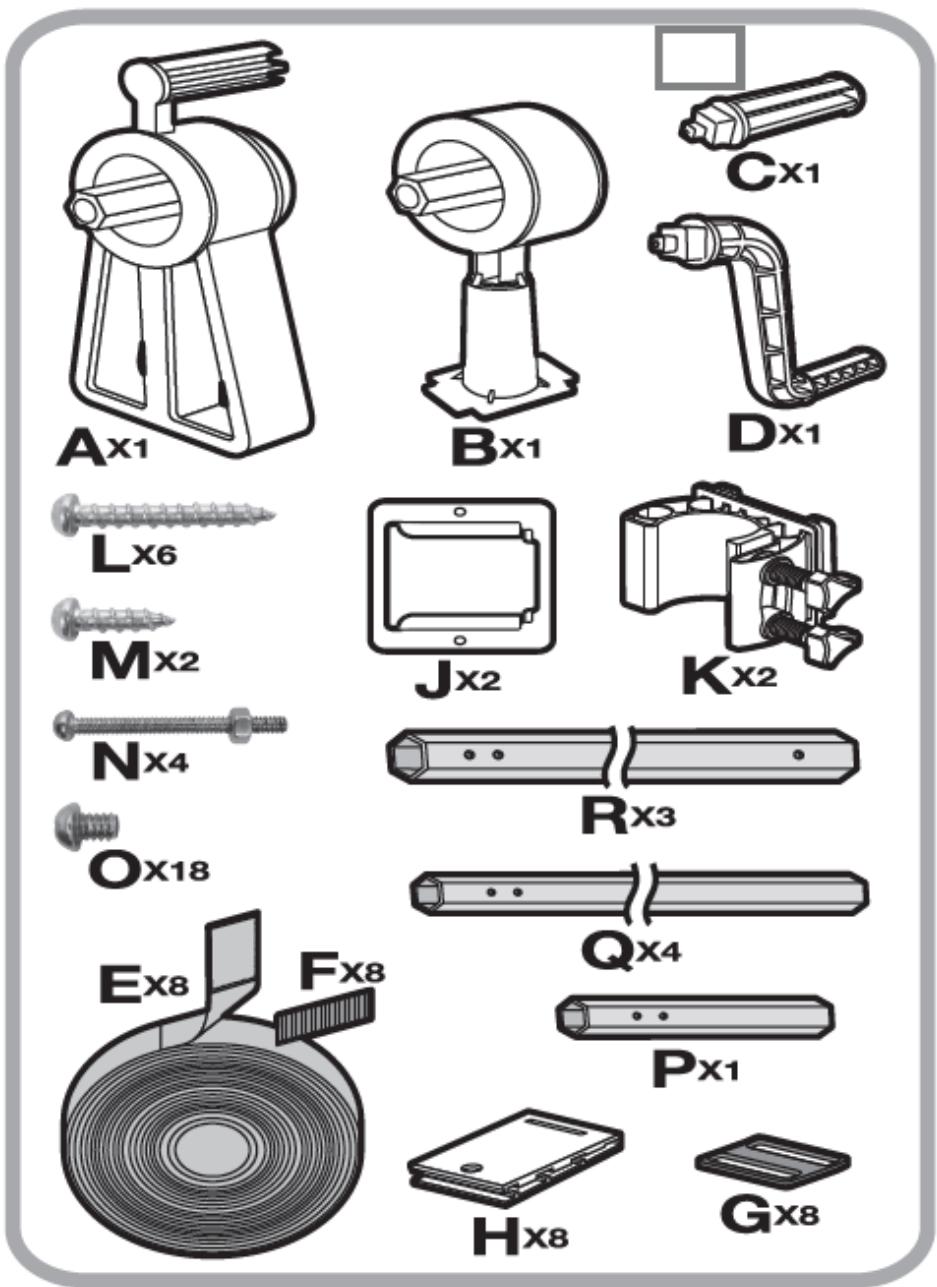
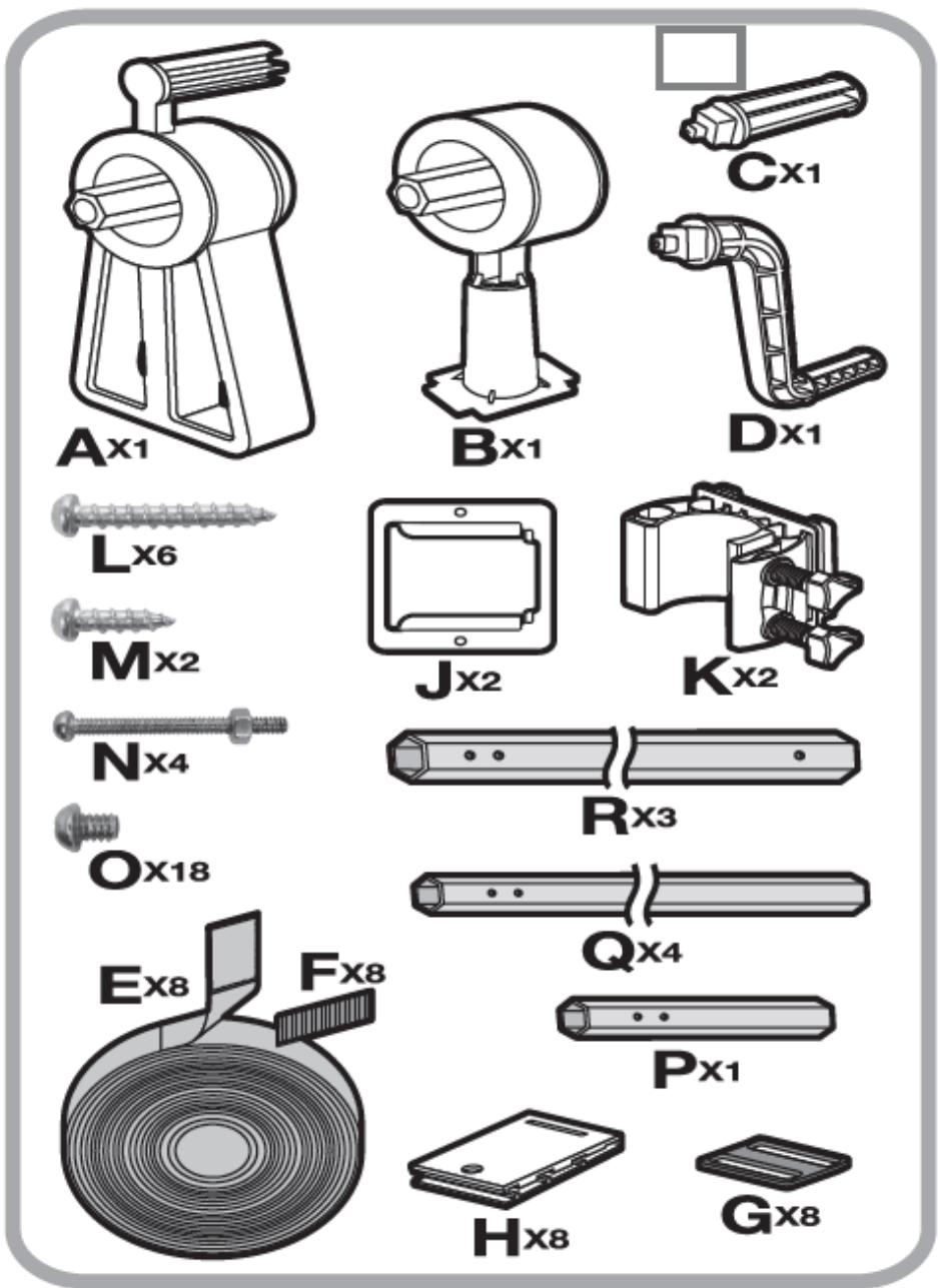
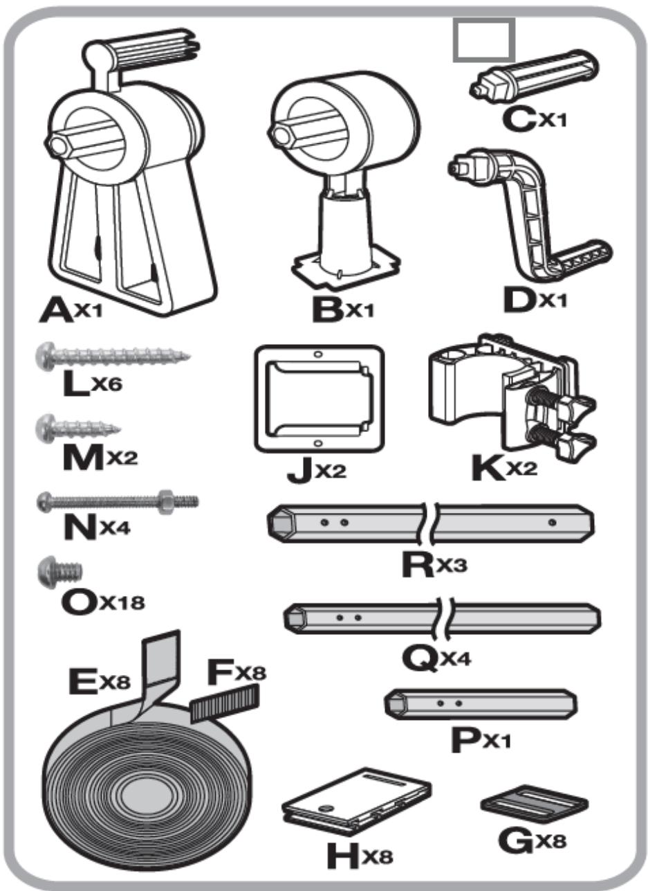
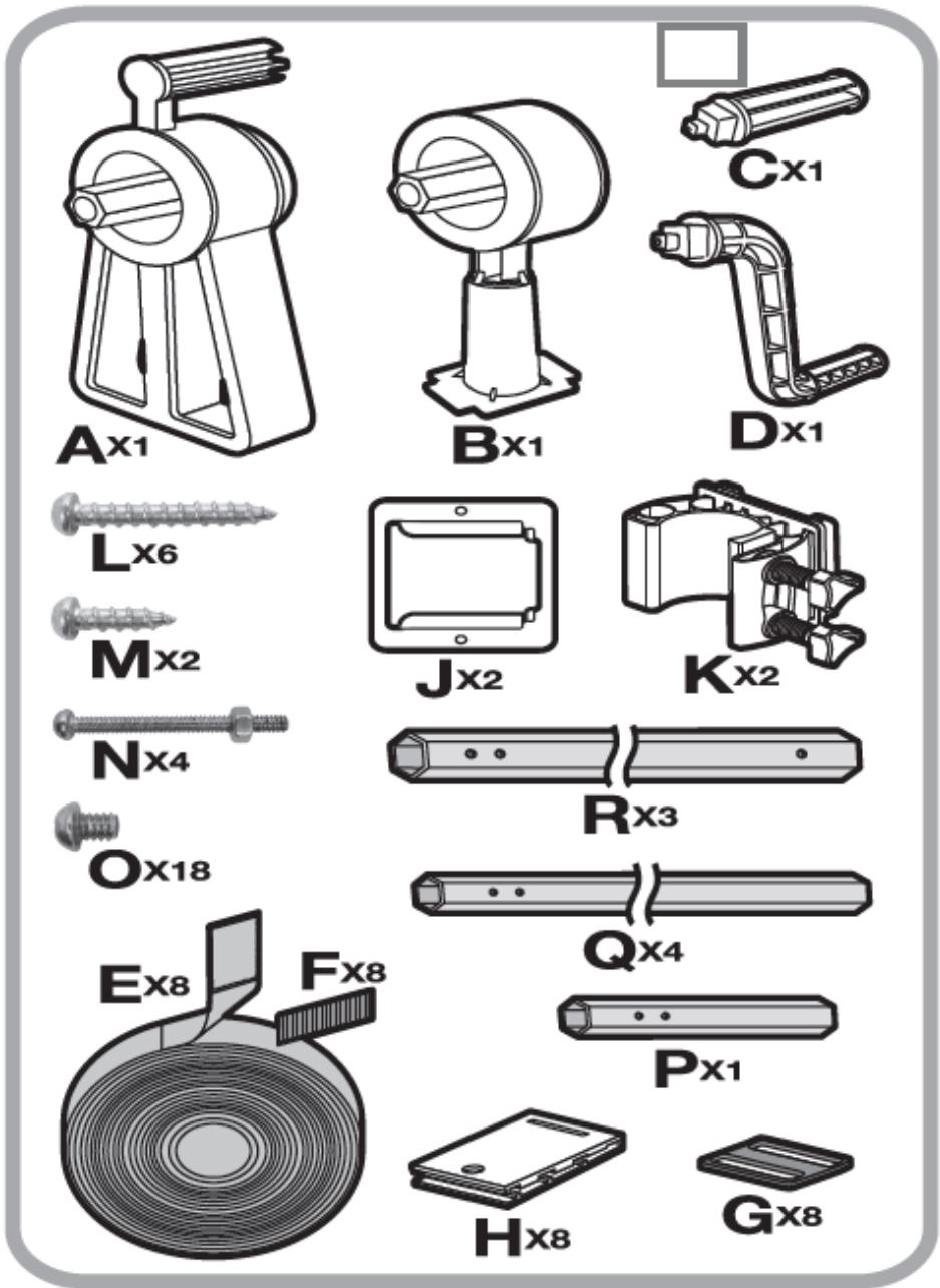
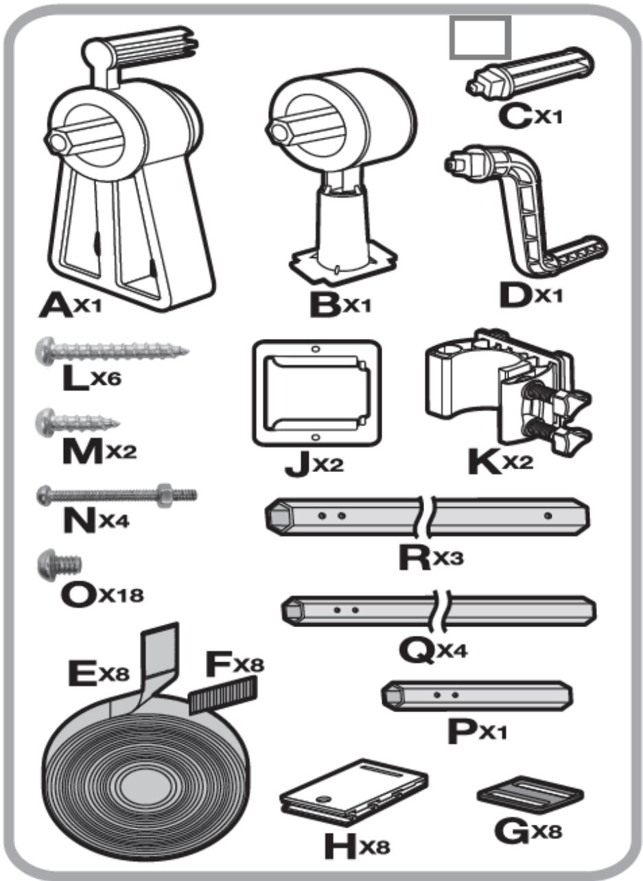
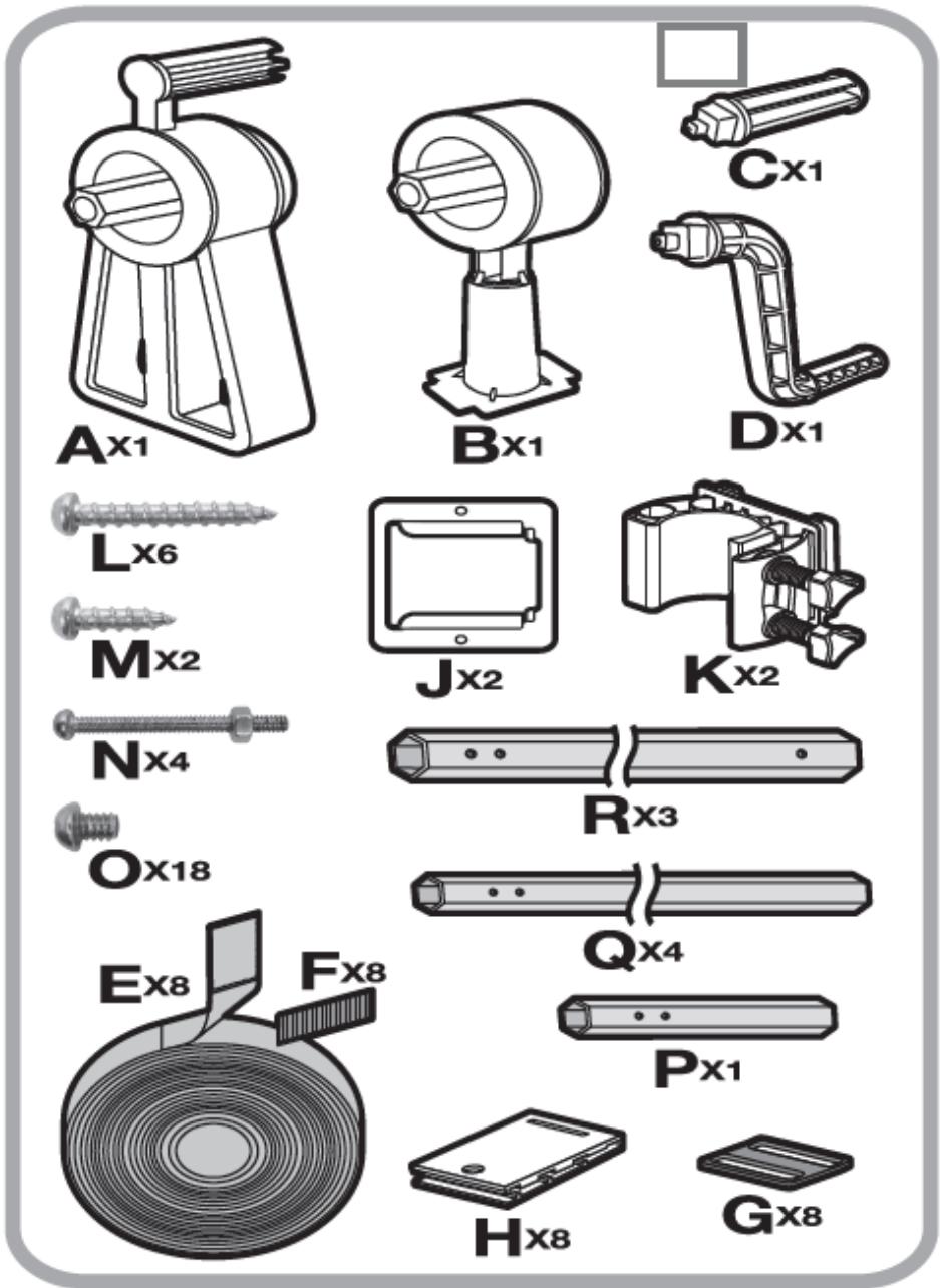
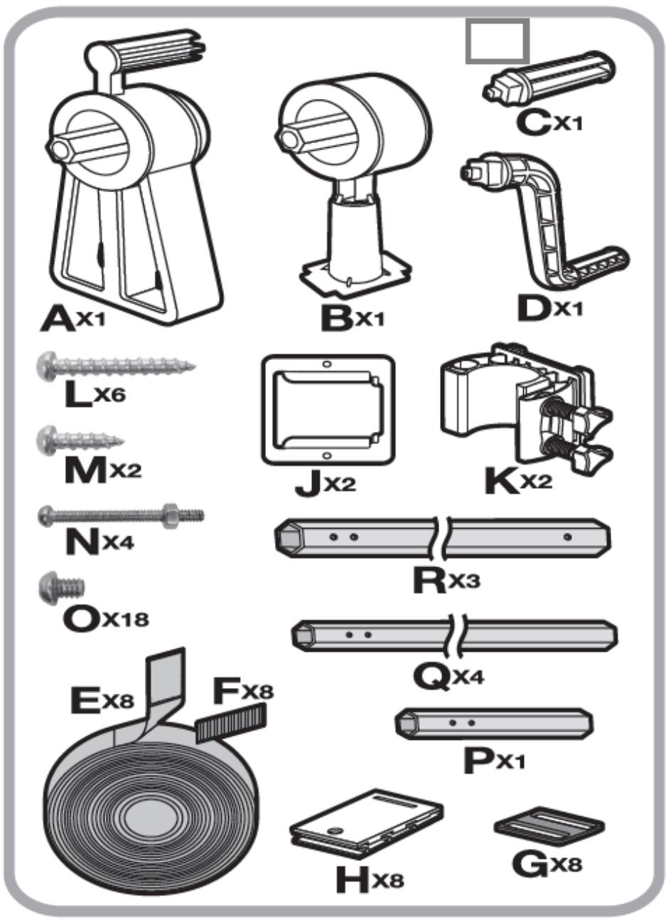
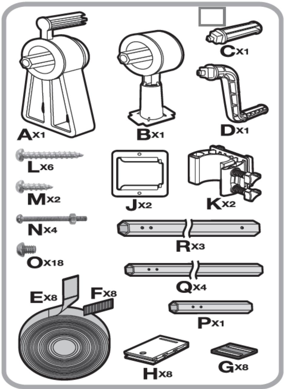
A×1 B×1 C×1 D×1 L×6 M×2 J×2 K×2 Nx4 Rx3 O×18 Ex8 Fx8 Q×4 Px1 H×8 G×8

Abb. 4.
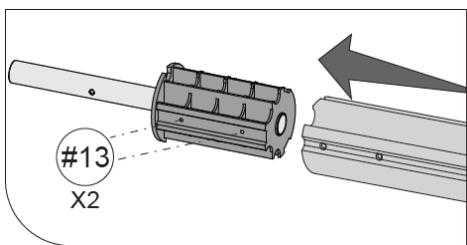
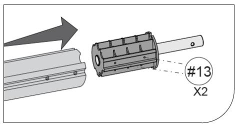
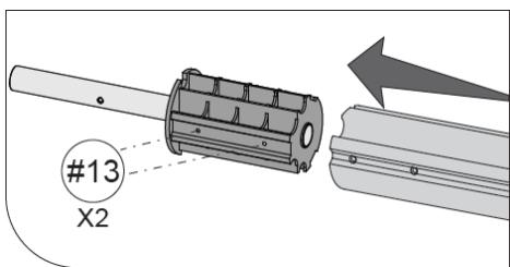
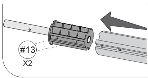
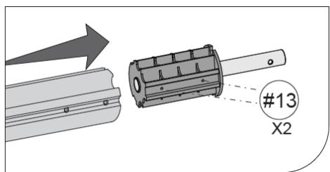
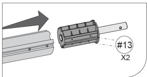
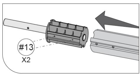
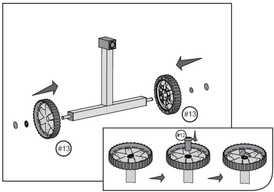
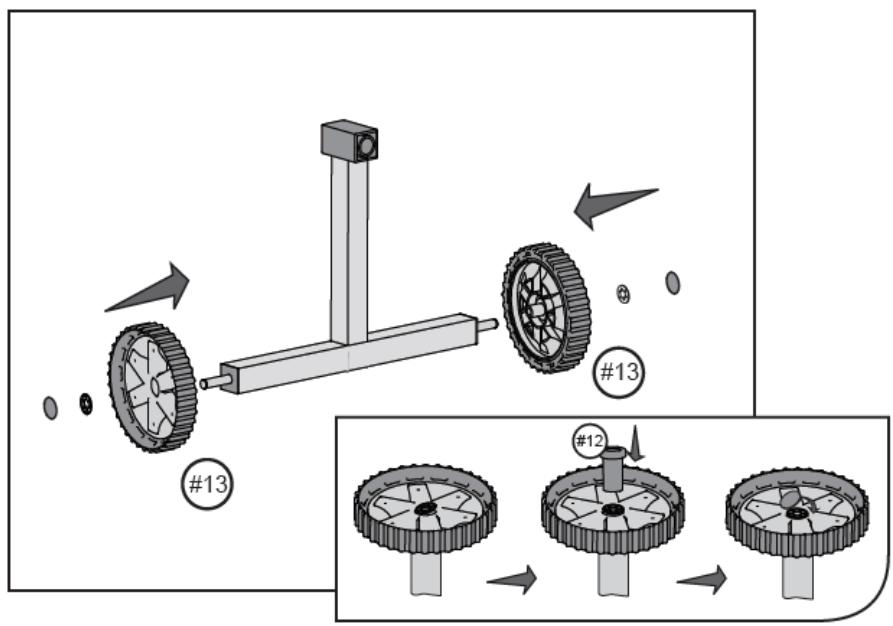
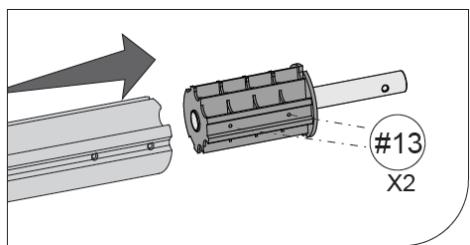
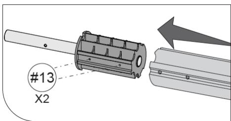
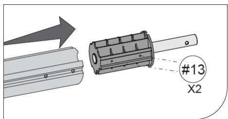
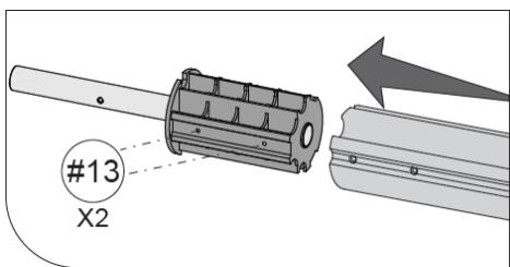
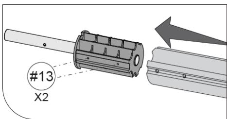
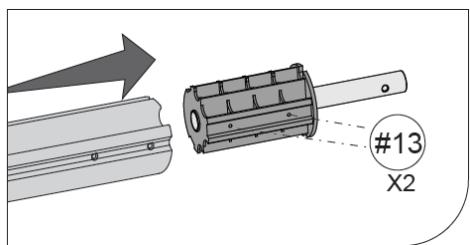
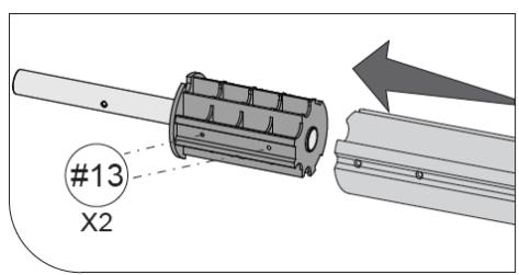
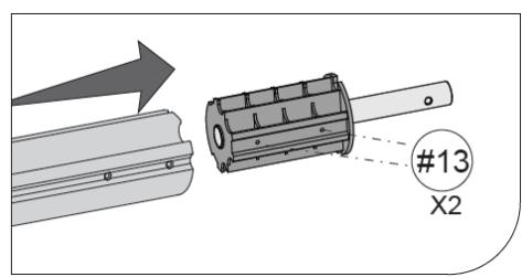
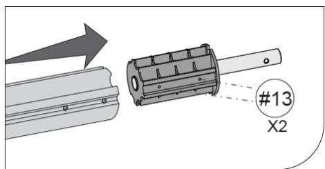
#13 X2

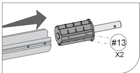
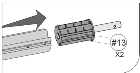
#13 X2

Abb. 5.
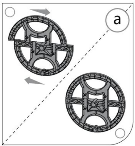
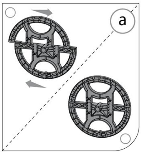
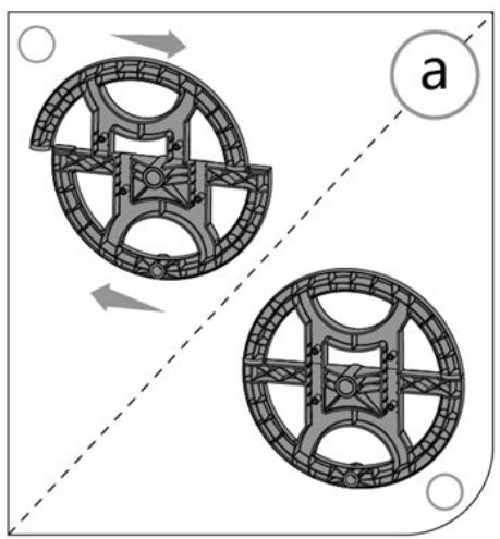
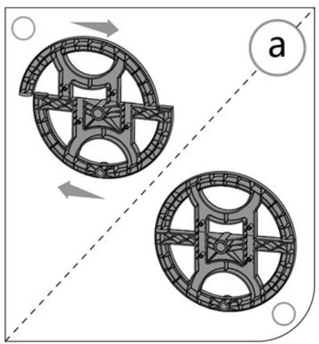
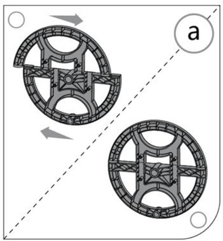
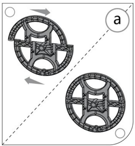
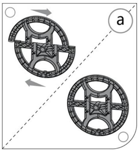
Diagram of two circular mechanical components with directional arrows, no text or symbols present

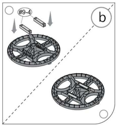
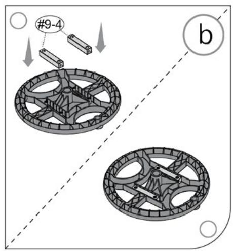
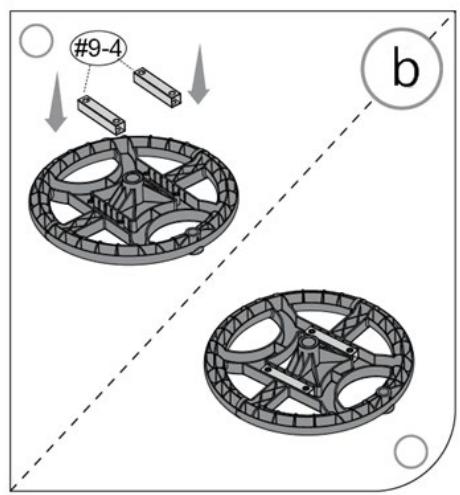
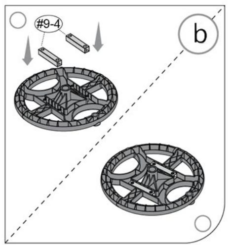
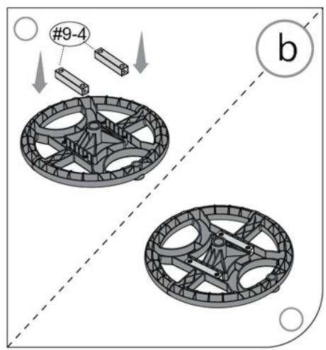
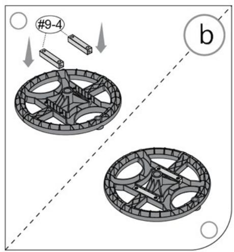
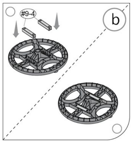
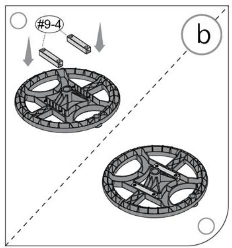
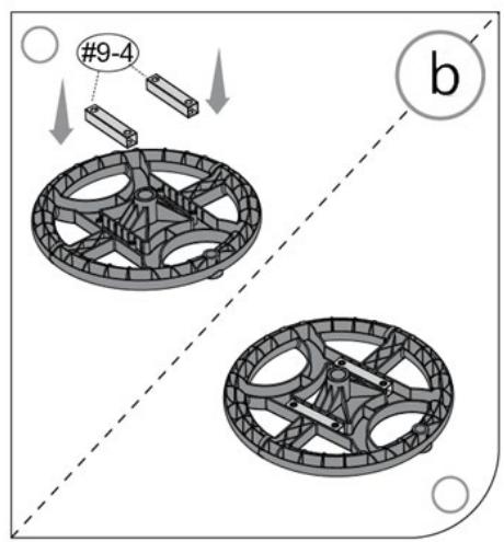
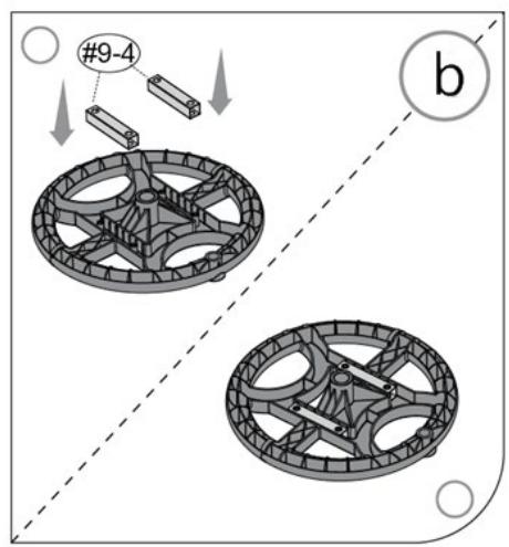
#9-4 b

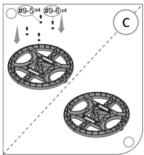
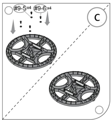
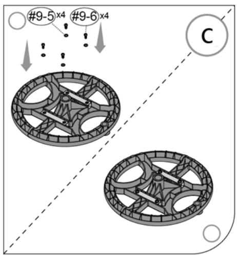
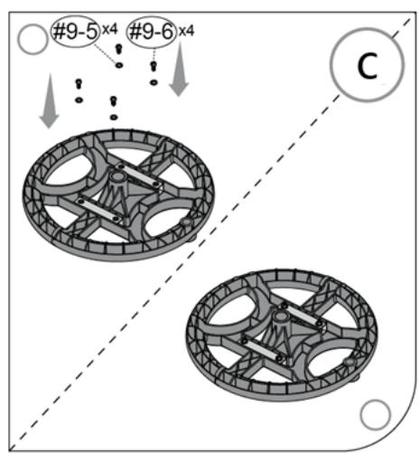
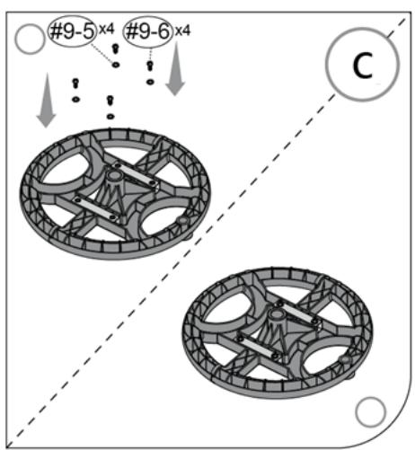
#9-5 x4 #9-6 x4 C

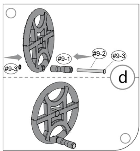
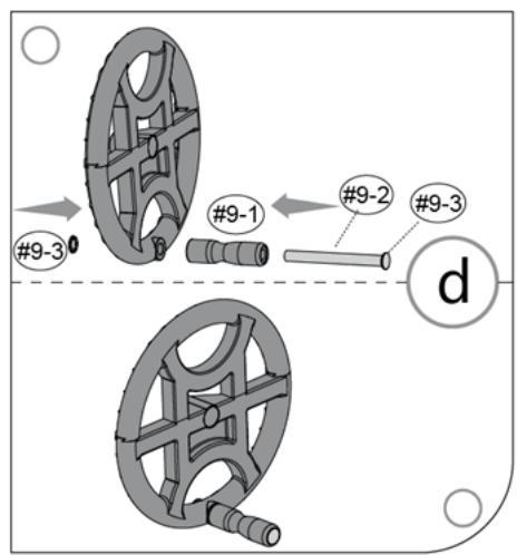
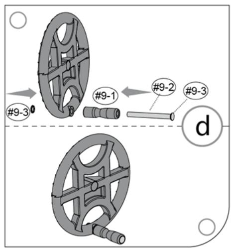
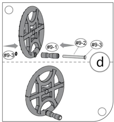
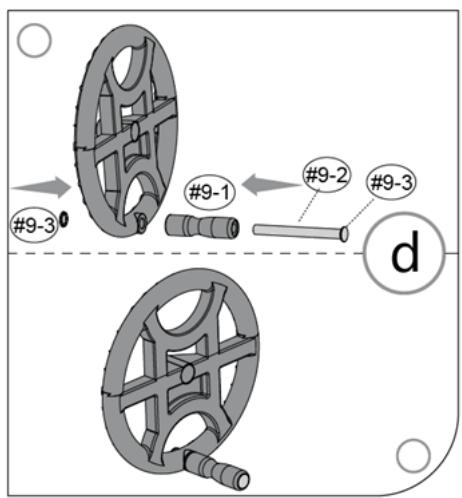
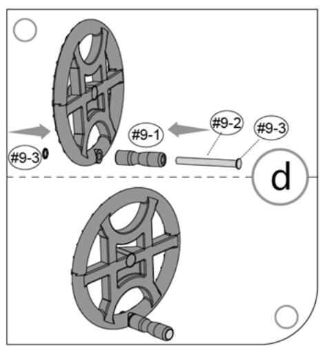
#9-3 #9-1 #9-2 #9-3 d

Abb. 6.
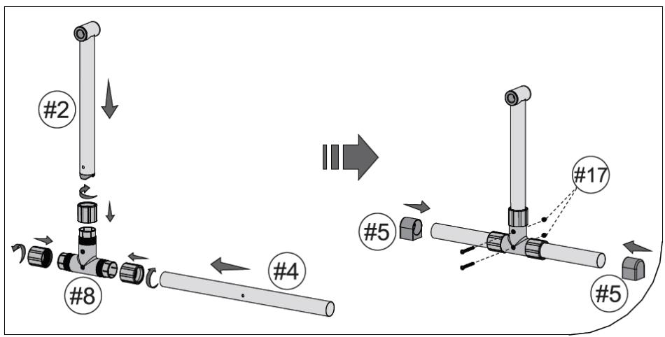
graph TD A["Step #2"] --> B["Assembly #8"] B --> C["Step #4"] C --> D["Assembly #5"] D --> E["Step #17"] E --> F["Assembly #5"] style A fill:#f9f,stroke:#333 style B fill:#ccf,stroke:#333 style C fill:#cfc,stroke:#333 style D fill:#fcc,stroke:#333 style E fill:#cff,stroke:#333 style F fill:#ffc,stro…

Abb. 7.
graph TD A["#1"] --> B["Engine"] B --> C["Engine 8"] C --> D["Engine 6"] D --> E["Engine 7"] E --> F["Engine 3"] F --> G["Engine 17"] G --> H["Engine 7"] style A fill:#f9f,stroke:#333 style B fill:#ccf,stroke:#333 style C fill:#cfc,stroke:#333 style D fill:#fcc,stroke:#333 style E fill:#cff,stroke:#…

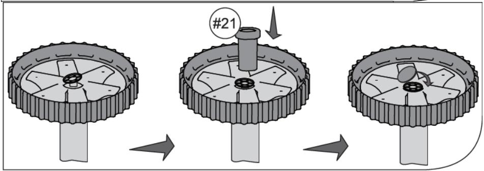
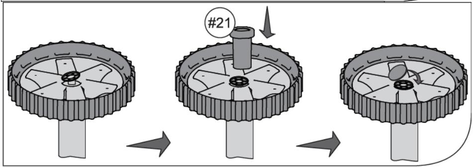
#21

Abb. 8.
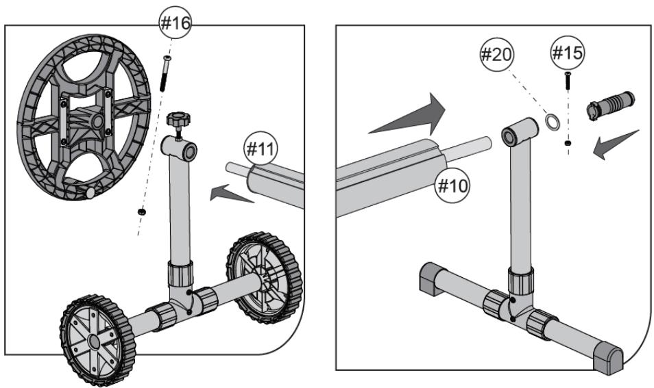
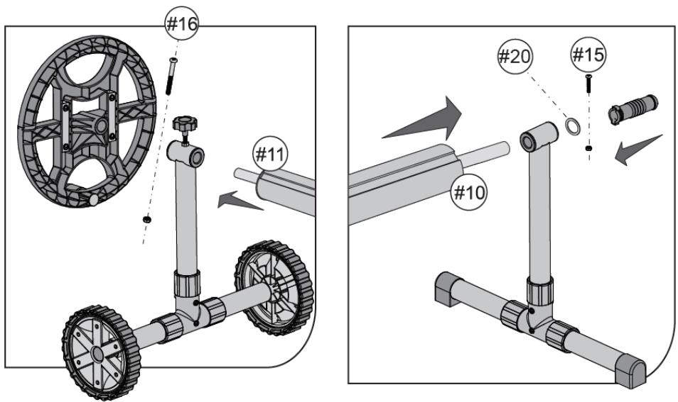
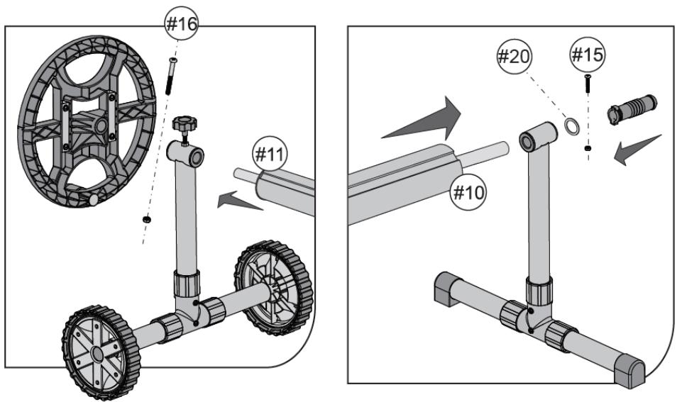
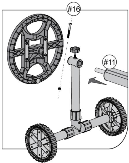
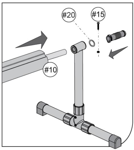
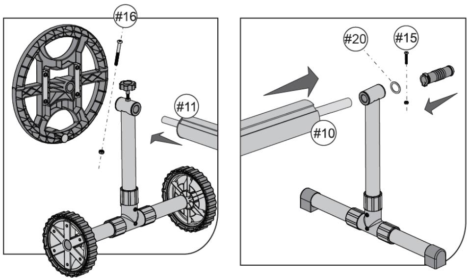
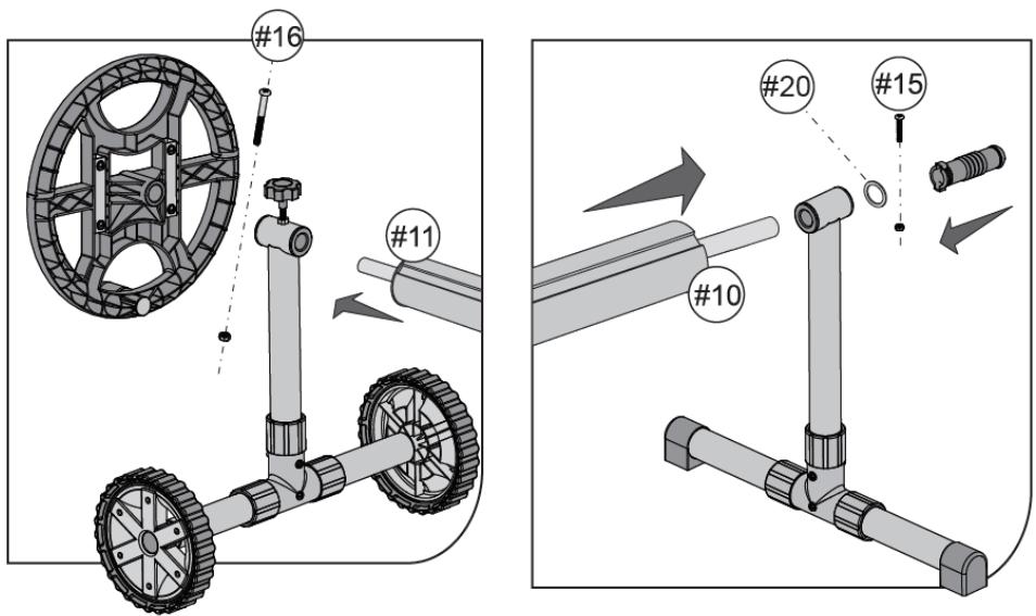
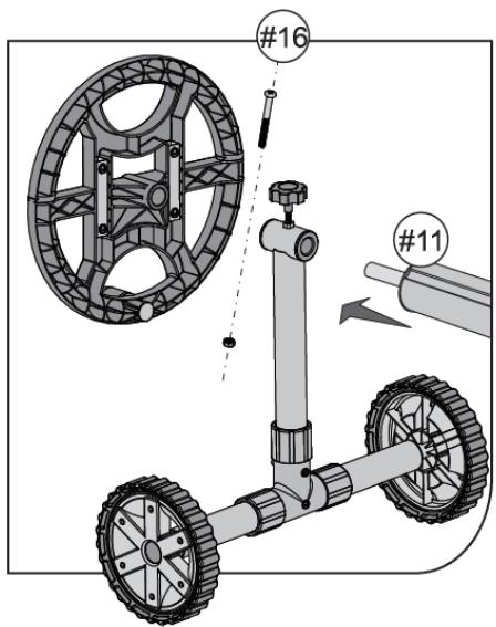
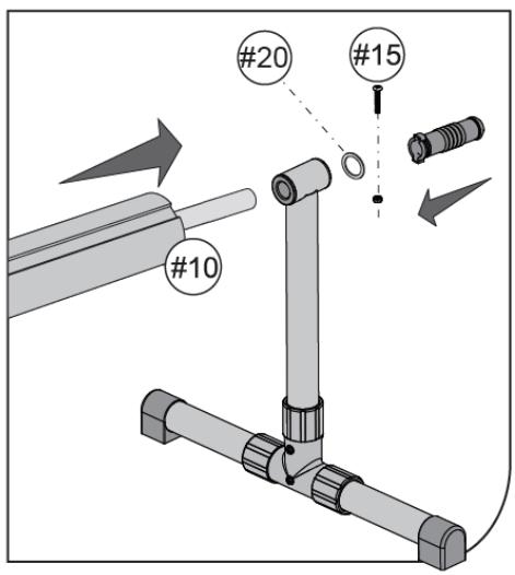
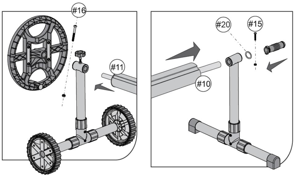
#16 #11 #20 #15 #10

Abb. 9.
Uniprodo UNI_POOL_REEL_585 - UNI_POOL_REEL_585 - 14

Abb. 10.
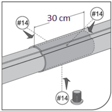
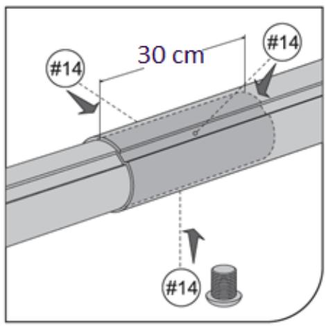
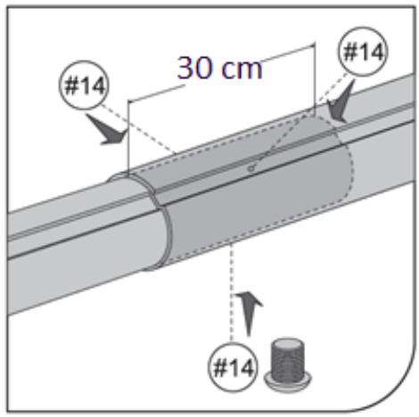
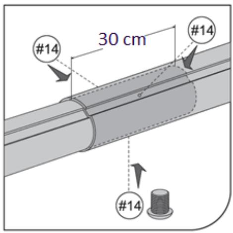
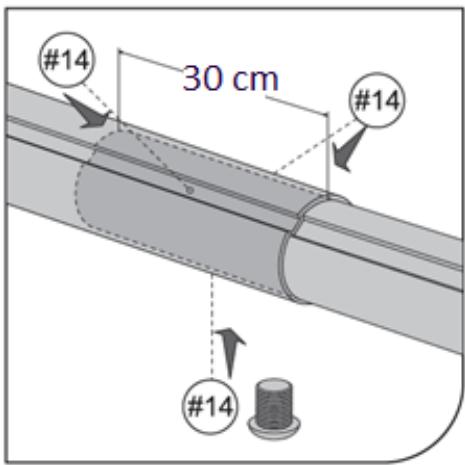
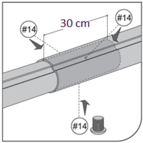
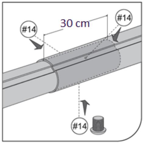
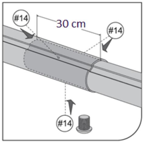
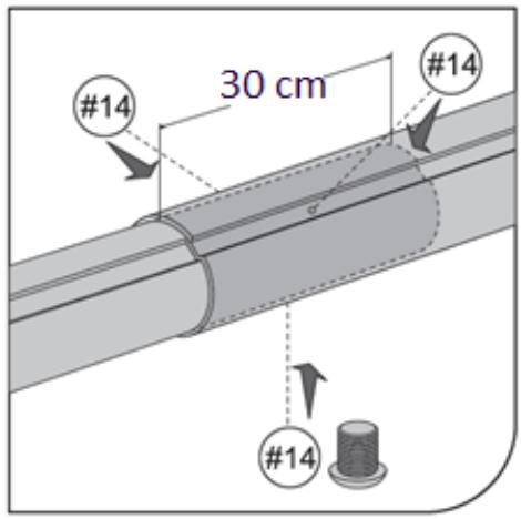
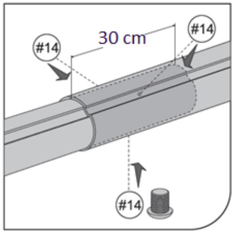
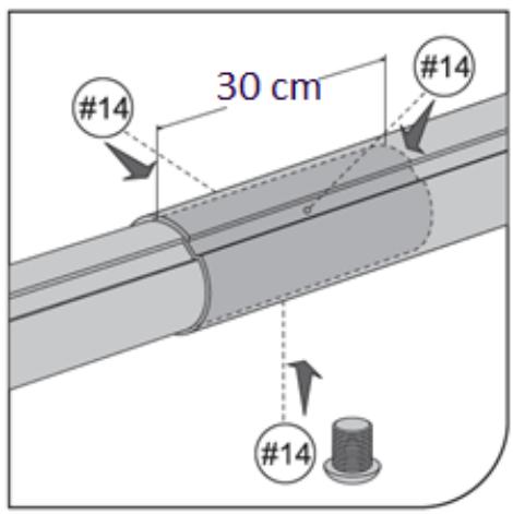
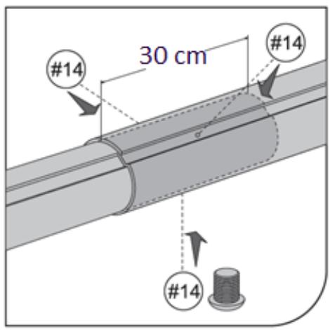
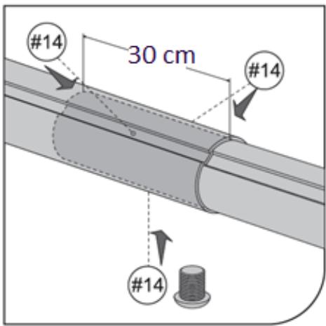
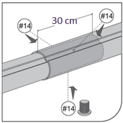
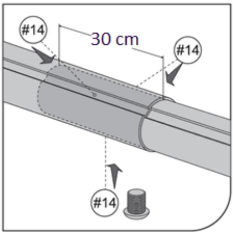
#14 30 cm #14 #14

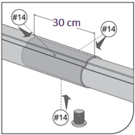
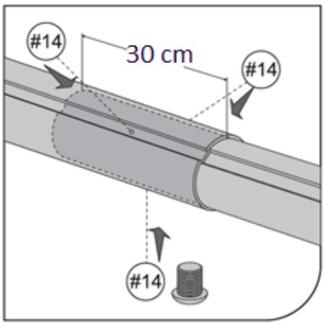
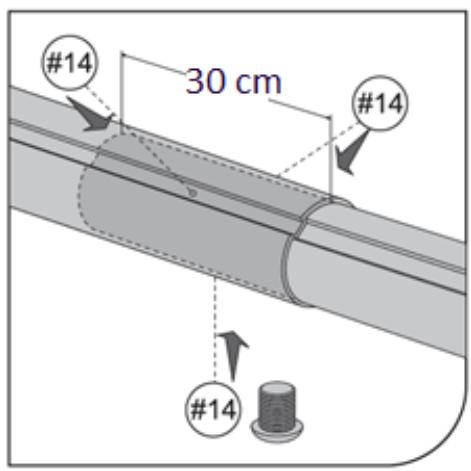
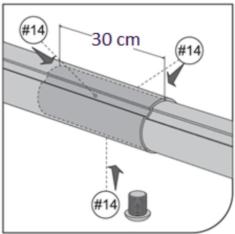
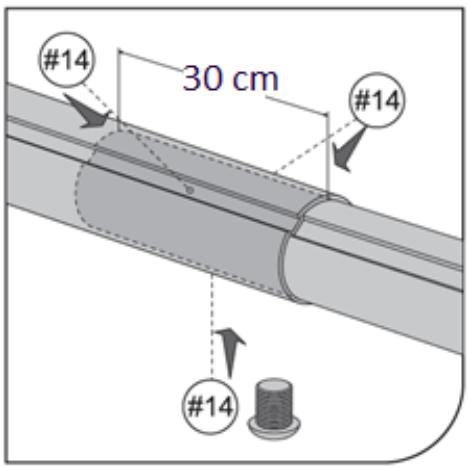
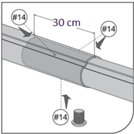
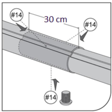
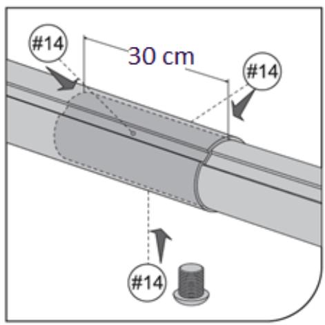
#14 30 cm #14 #14

Abb. 11
Diagram showing two panels with curved arrows indicating rotation or movement (no text or symbols)

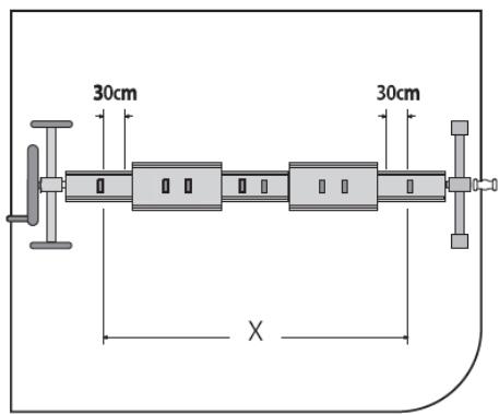
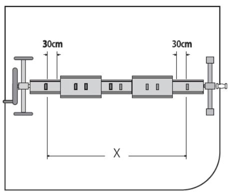
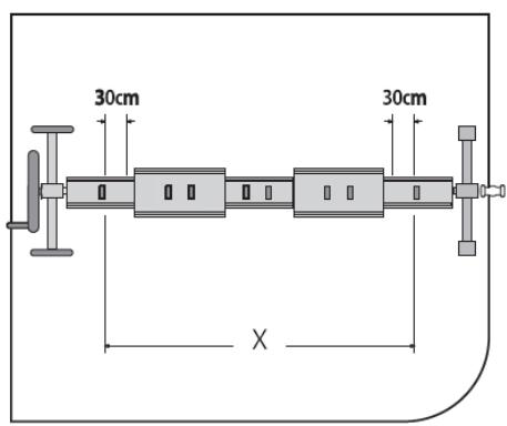
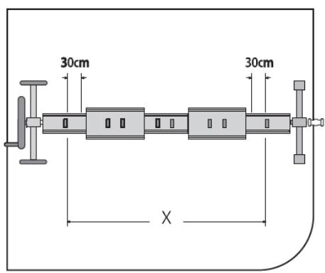
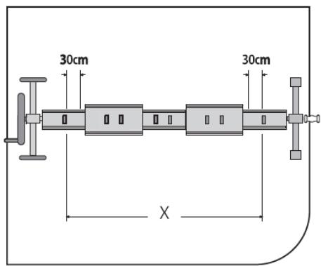
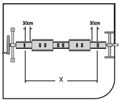
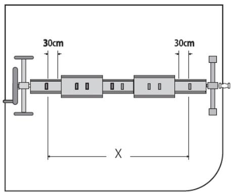
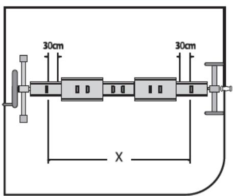
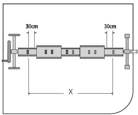
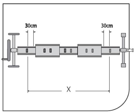
30cm 30cm X

Abb. 12.
Diagram of a mechanical assembly with directional arrows indicating flow or movement (no text or symbols present)

Abb. 13.
Pure electrical circuit lines without any symbols

Technical illustration of a mechanical clamp or bracket assembly (no text or symbols visible)

Abb. 14.
Pure mechanical diagram of a cylindrical device with attached clamps and a base, without any text, numbers, or symbols.

Technical line drawing of a mechanical clamp or bracket assembly (no text or symbols)

Abb. 15.

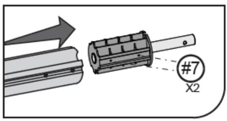
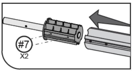
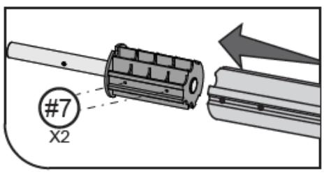
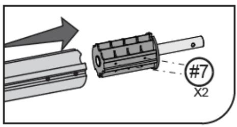
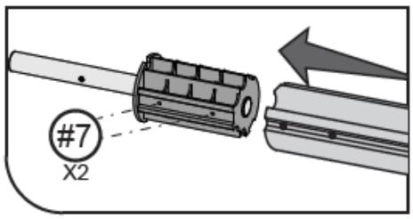
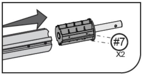
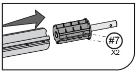
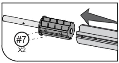
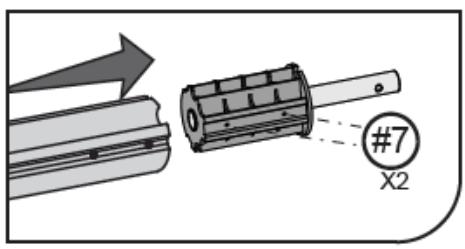
#7 X2

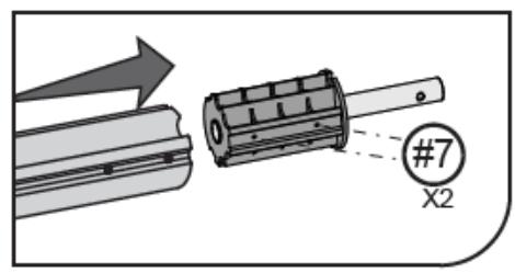
#7 X2

Abb. 16.

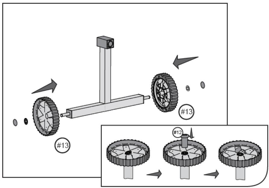
Technical diagram illustrating gear assembly with numbered components and directional arrows, including a close-up of the final gear assembly.

Abb. 17.

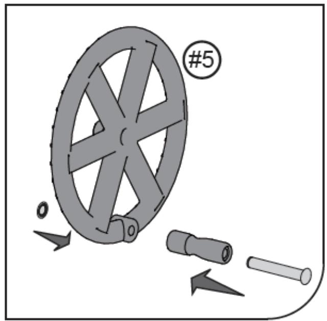
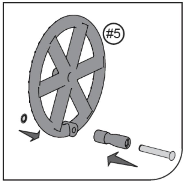
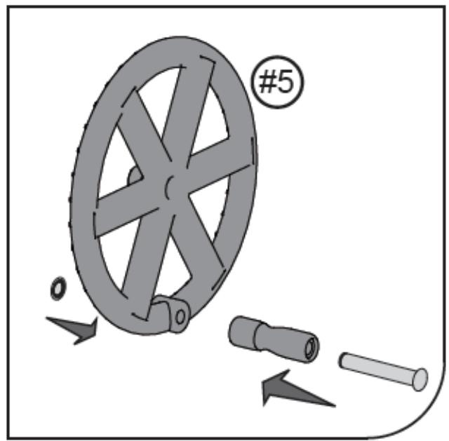
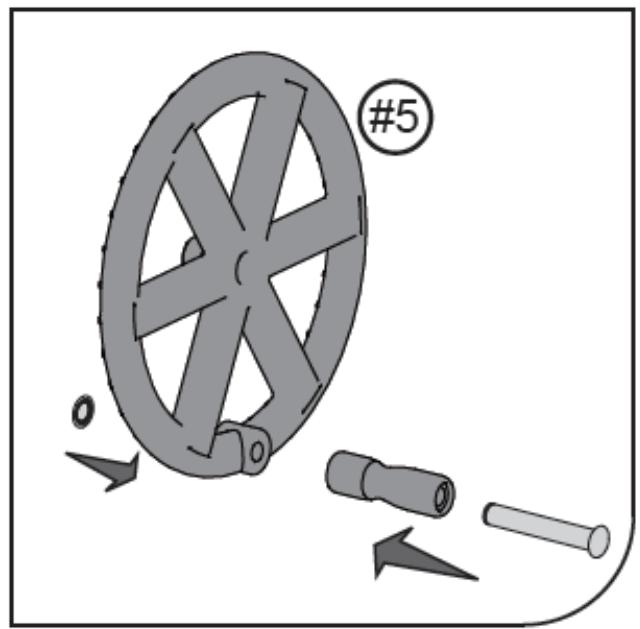
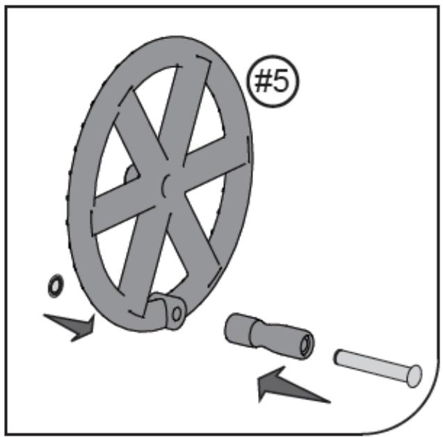
#5

Abb. 18.
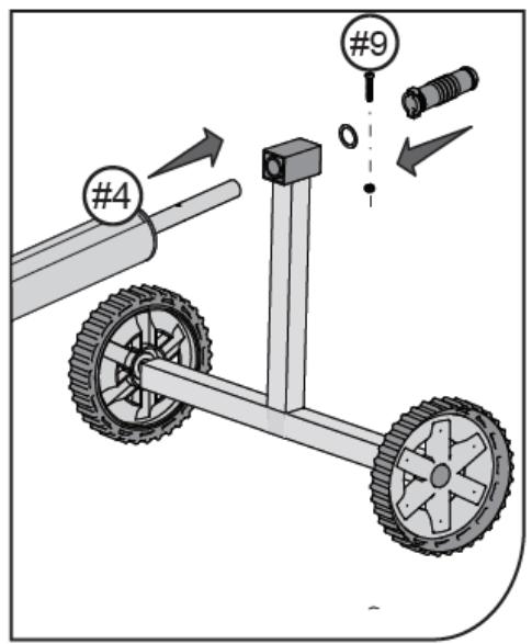
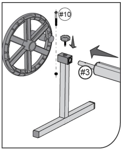
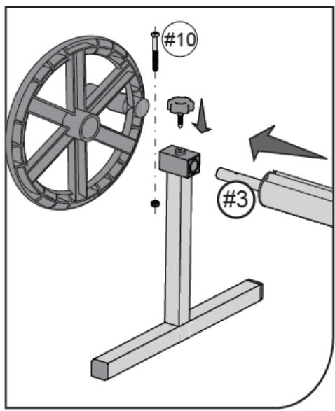
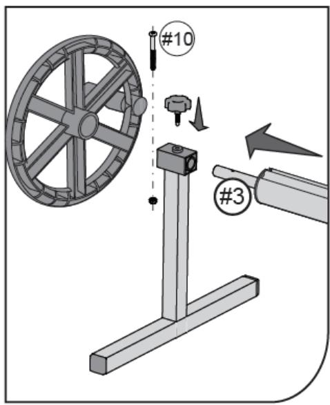
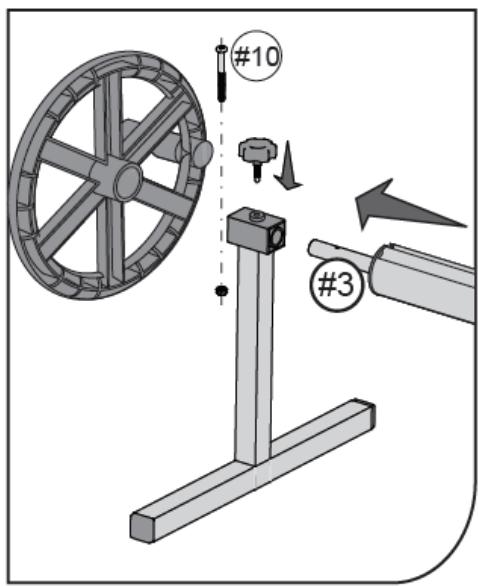
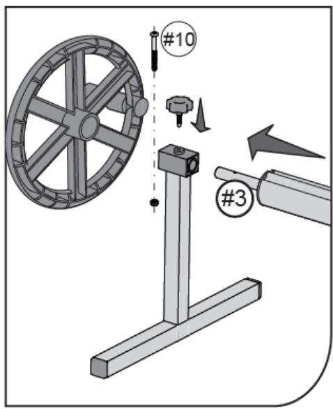
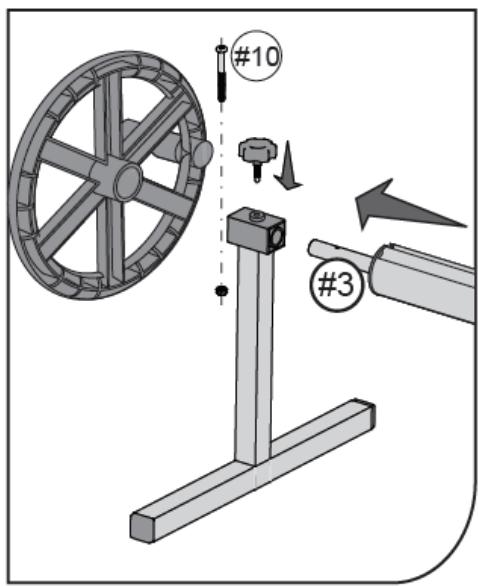
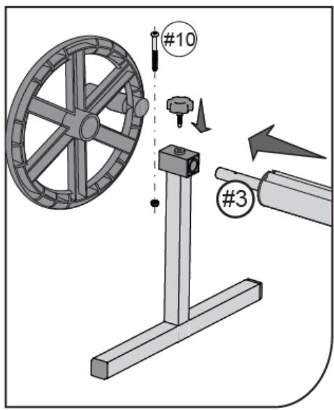
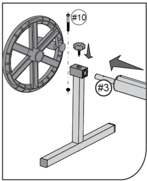
#10 #3

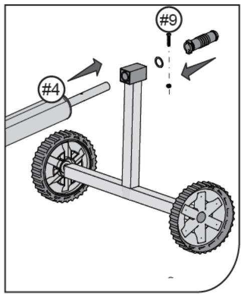
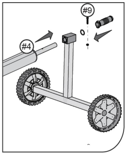
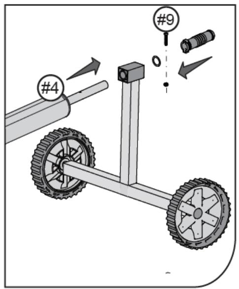
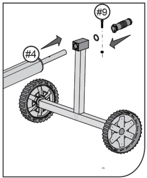
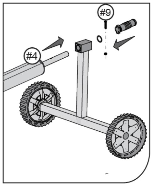
#4 #9

Abb. 19
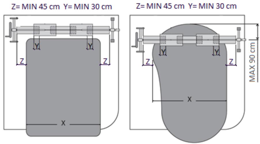
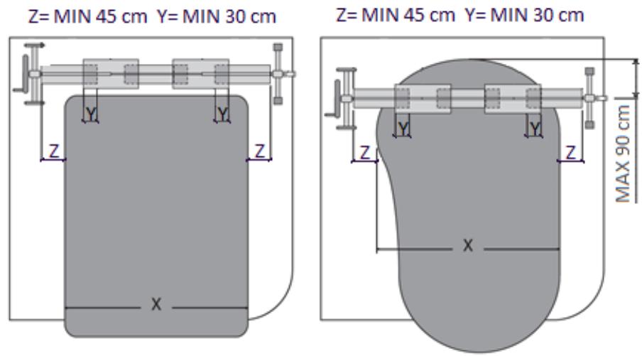
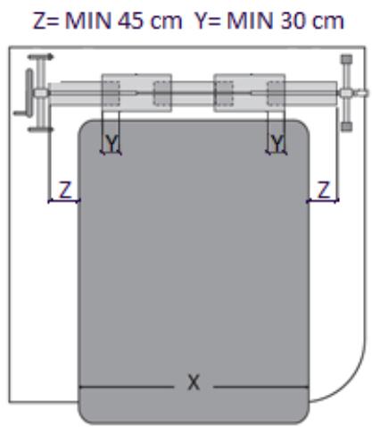
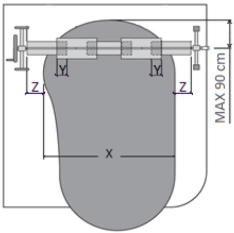
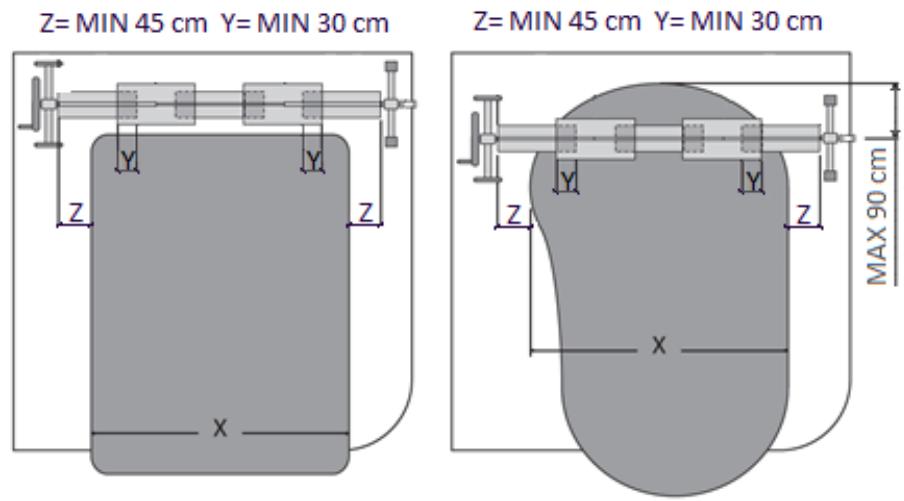
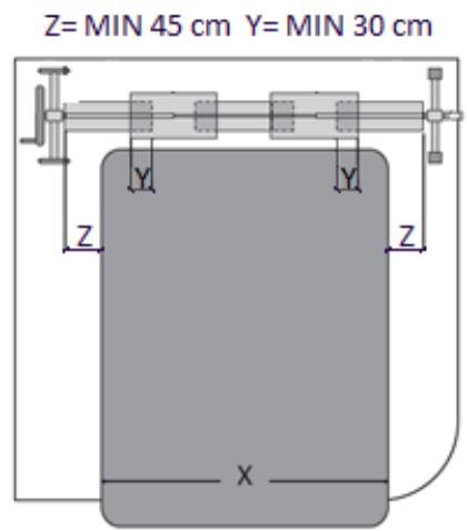
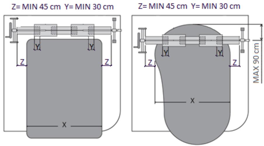
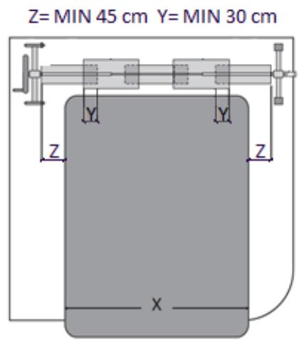
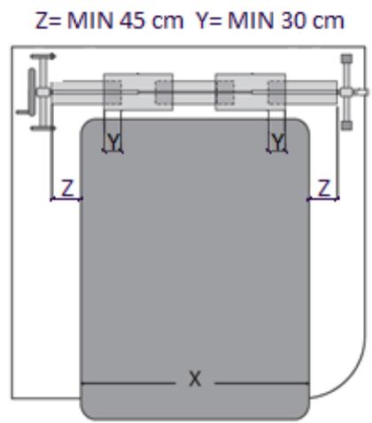
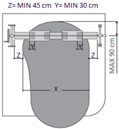
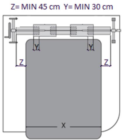
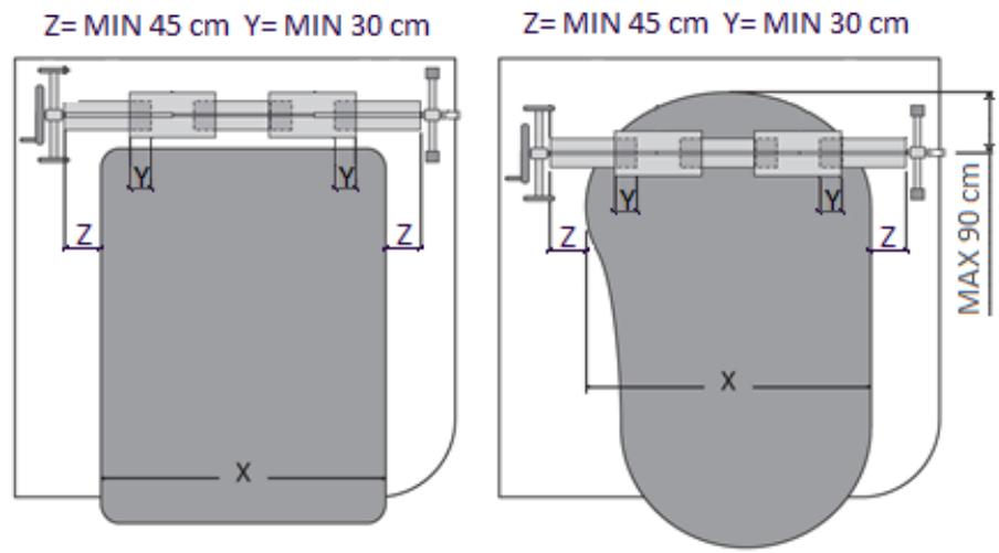
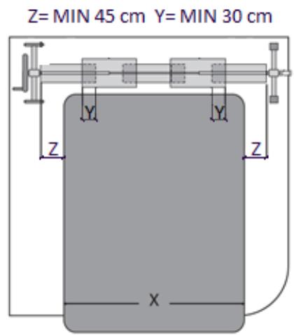
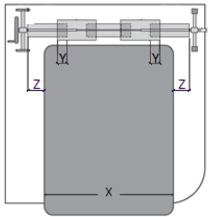
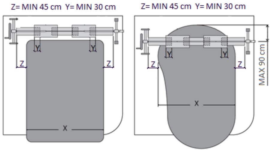
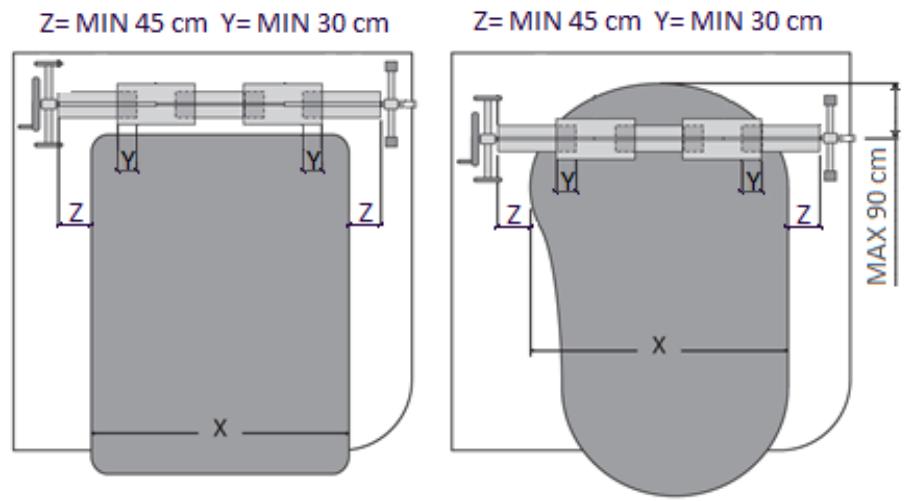
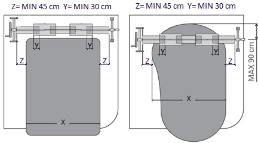
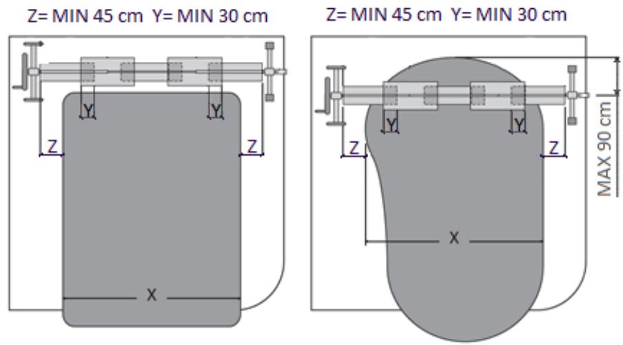
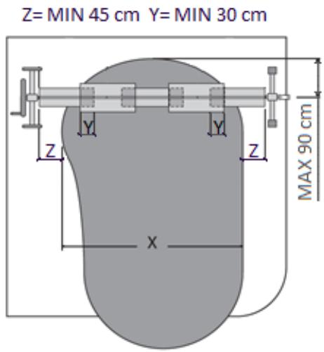
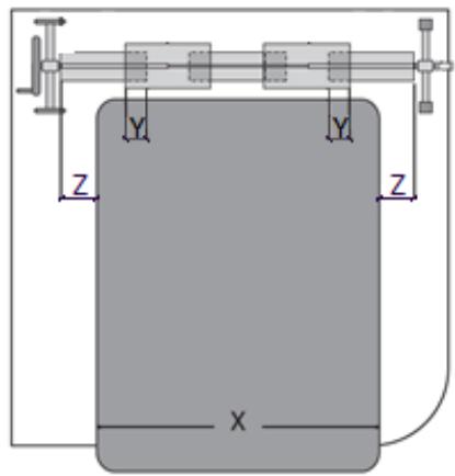
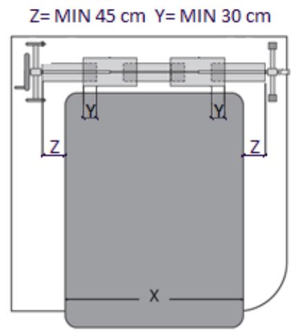
Z= MIN 45 cm Y= MIN 30 cm Z Y Y Z X

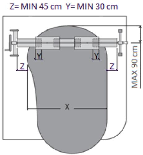
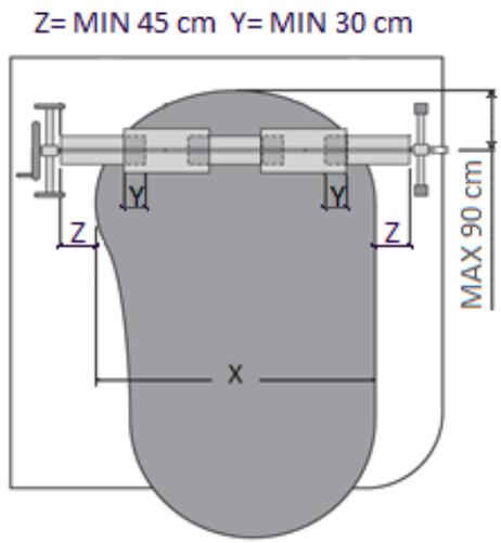
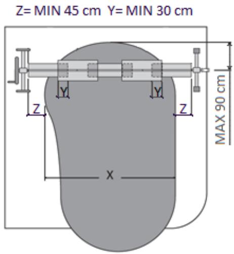
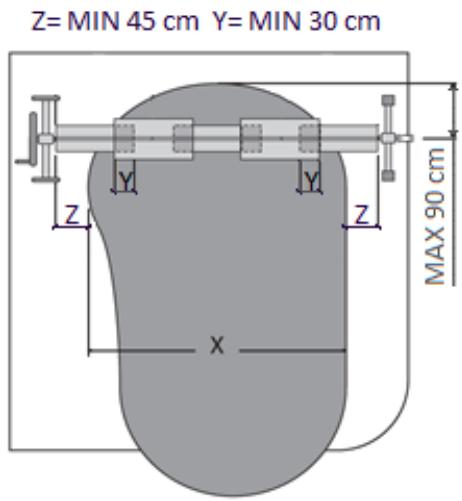
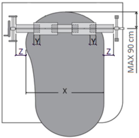
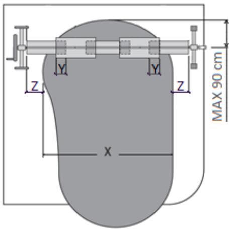
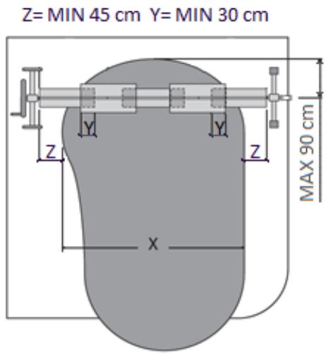
Z= MIN 45 cm Y= MIN 30 cm MAX 90 cm Z Y Y Z X

Abb. 20.
Diagram showing airflow or heat transfer between two panels, with arrows indicating direction (no text or symbols)

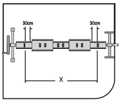
30cm 30cm X

Abb. 21.
Diagram of a mechanical component with directional arrows indicating motion or flow (no text or symbols)

Abb. 22.
Pure electrical circuit lines without any symbols

Technical illustration of a mechanical clamp or bracket assembly (no text or symbols visible)

Abb. 23.
Diagram of a mechanical device with a central component and two vertical supports, enclosed in a rectangular frame (no text or symbols)

Technical illustration of a mechanical clamp or bracket assembly (no text or symbols visible)

Abb. 24.
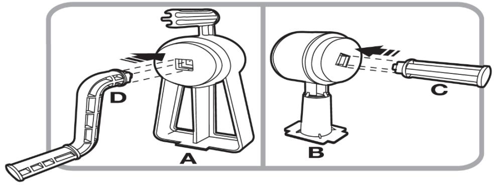
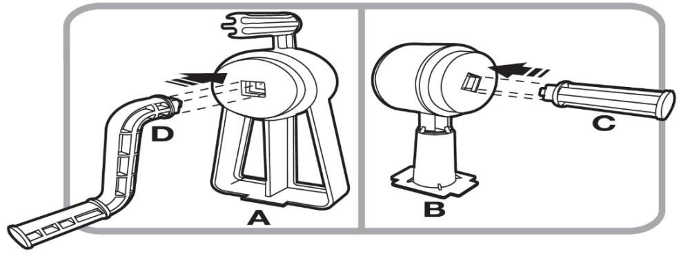
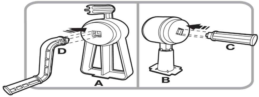
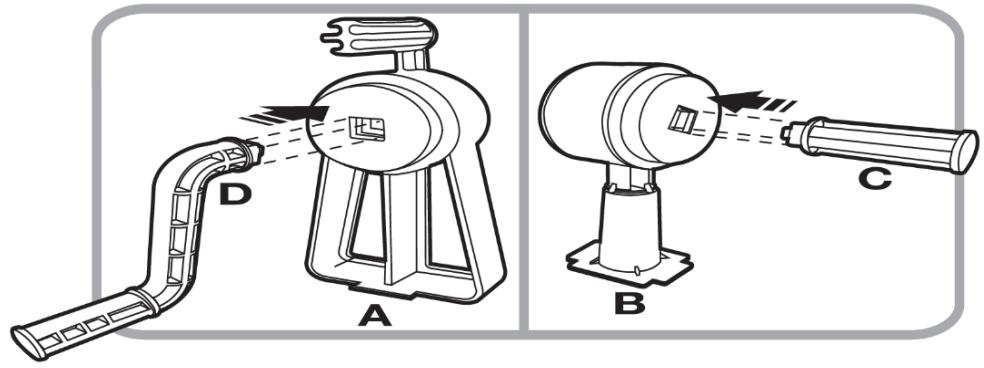
Technical diagram showing three different types of spray gun components labeled A, B, and C, with component D indicated.

Abb. 25.
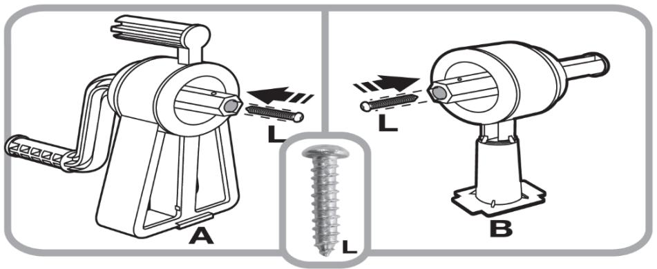
Technical diagram showing two types of hair feeders (A and B) with labeled parts and screw installation details.

Abb. 26.

Technical diagram showing exploded and assembled views of electrical switchgear components with labeled parts A, B, and J.

Abb. 27
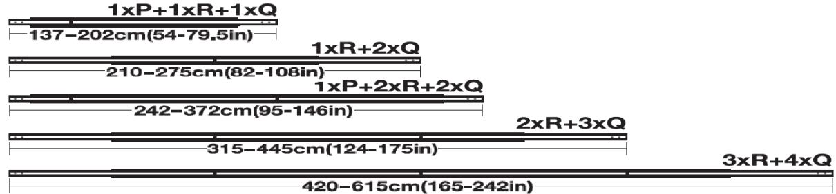
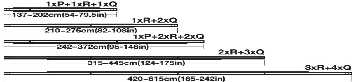
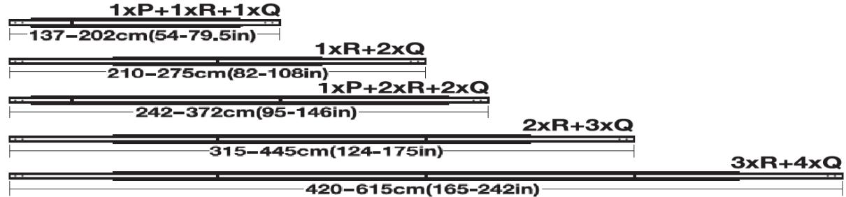
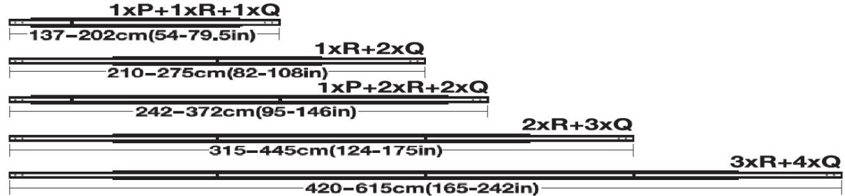
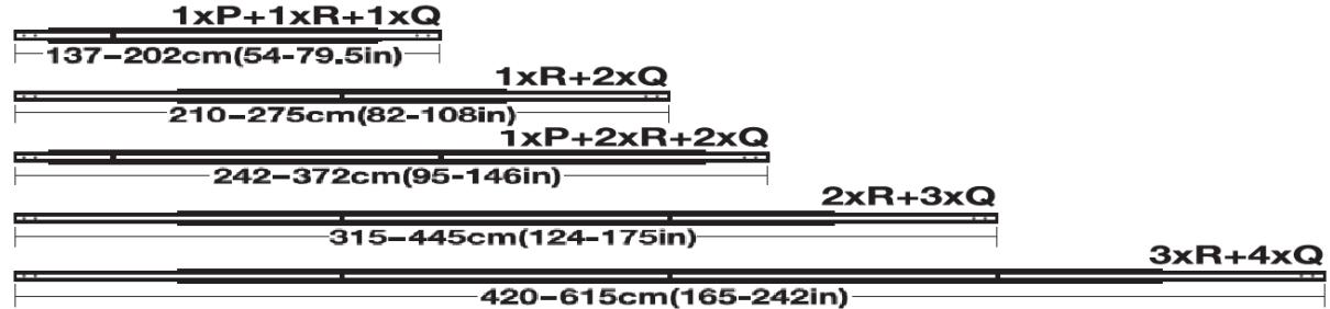
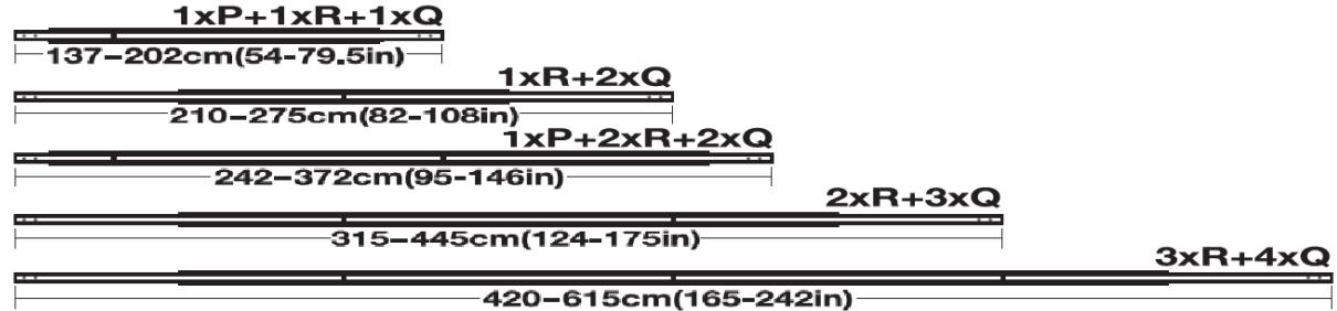
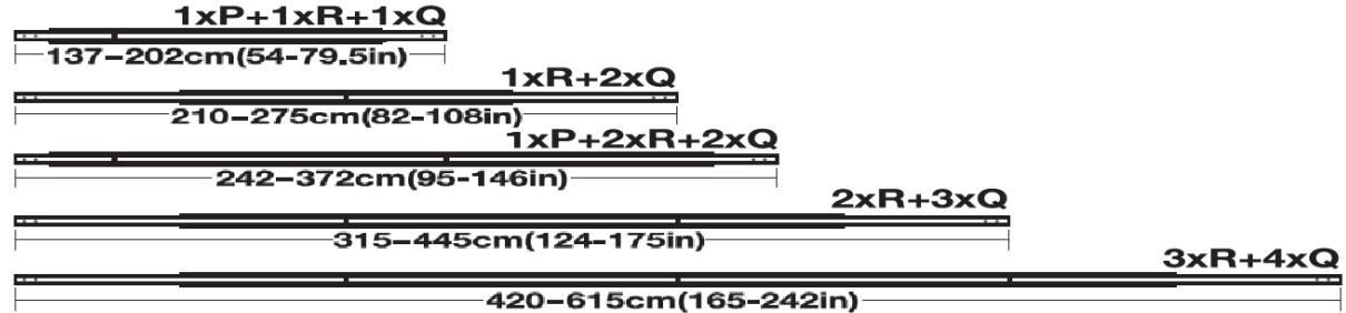
| Dimension | Value | |---|---| | 1xP+1xR+1xQ | 137-202cm(54-79.5in) | | 1xR+2xQ | 210-275cm(82-108in) | | 1xP+2xR+2xQ | 242-372cm(95-146in) | | 2xR+3xQ | 315-445cm(124-175in) | | 3xR+4xQ | 420-615cm(165-242in) |

Abb. 28.
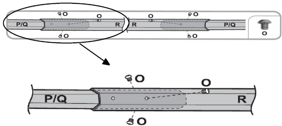
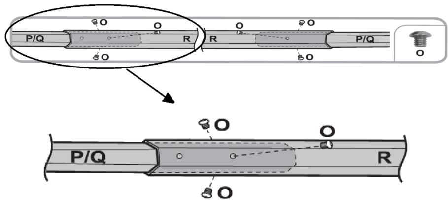
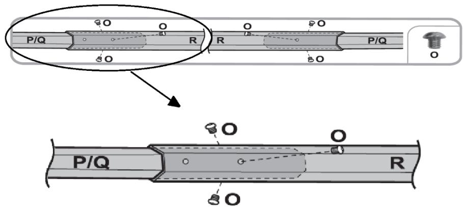
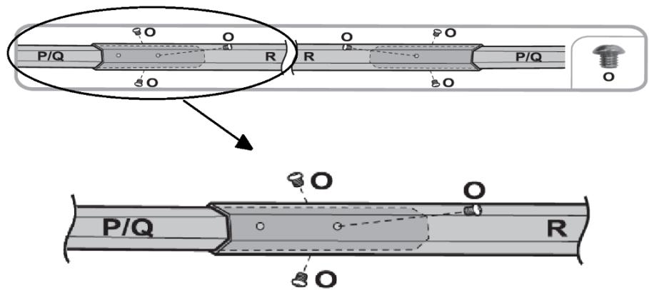
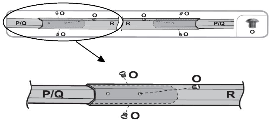
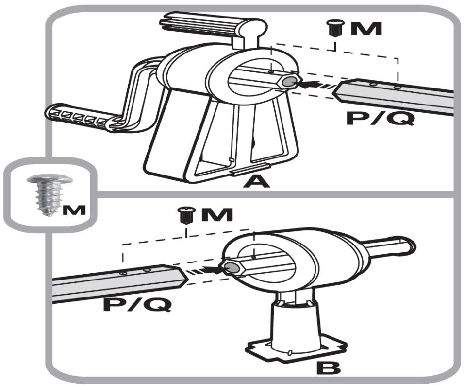
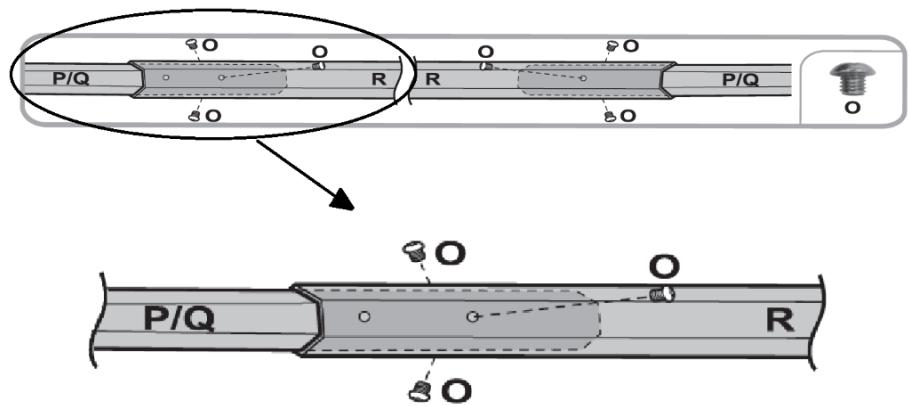
P/Q R R P/Q O O O O O O P/Q R

Abb. 29.
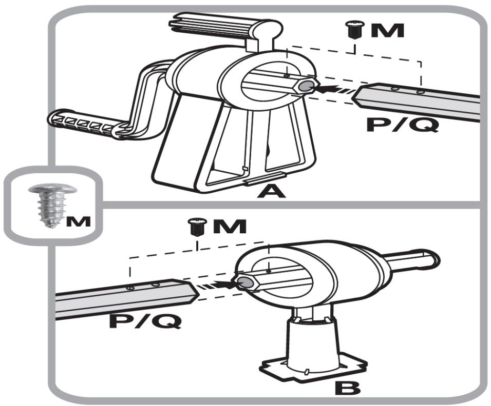
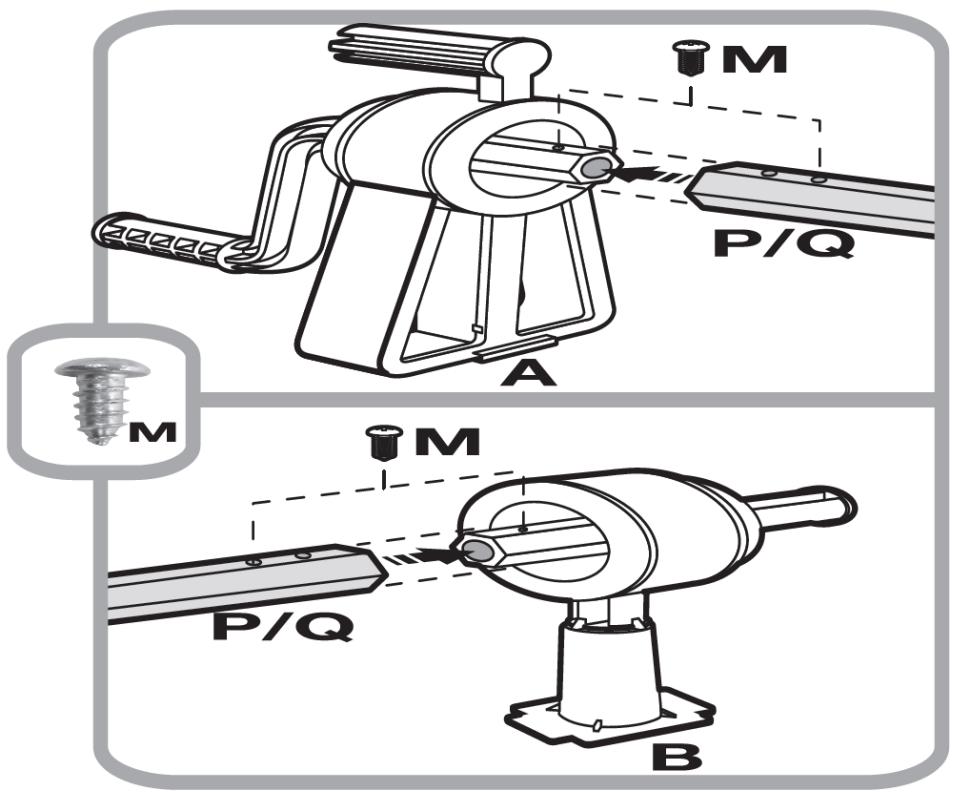
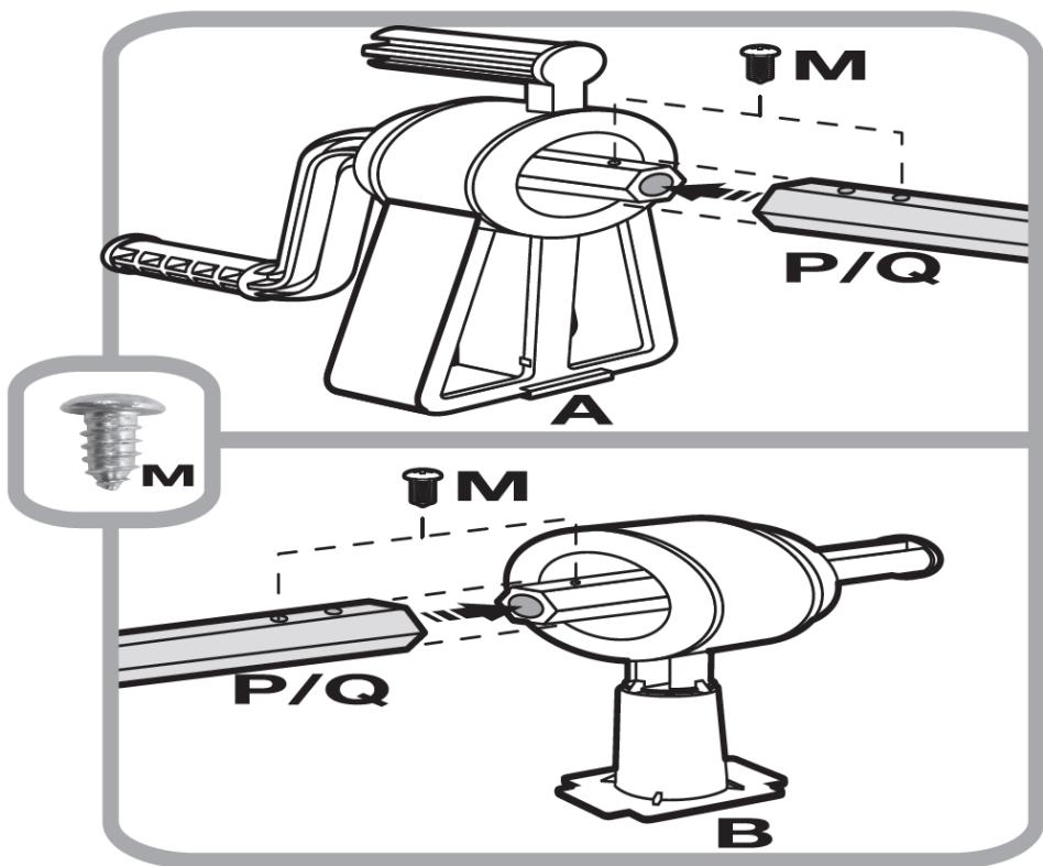
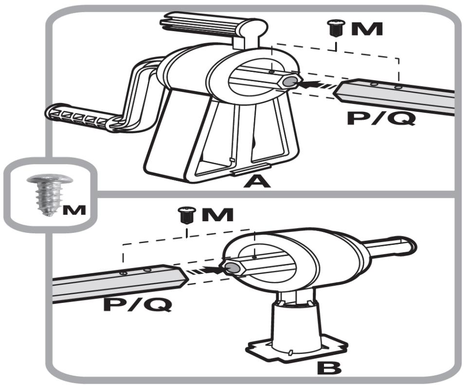
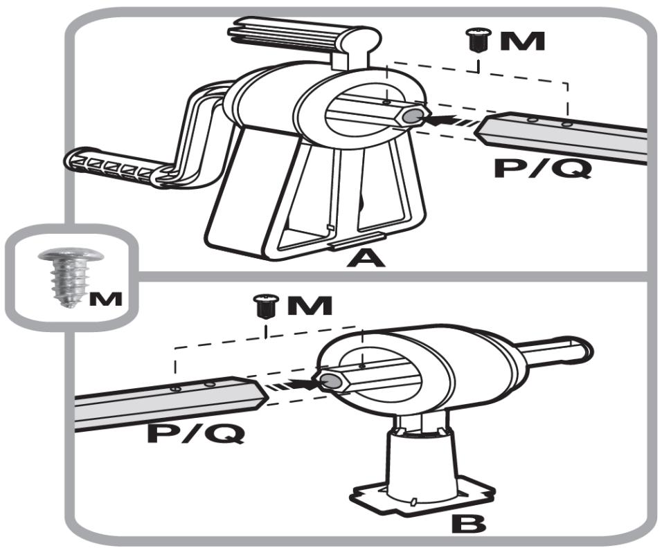
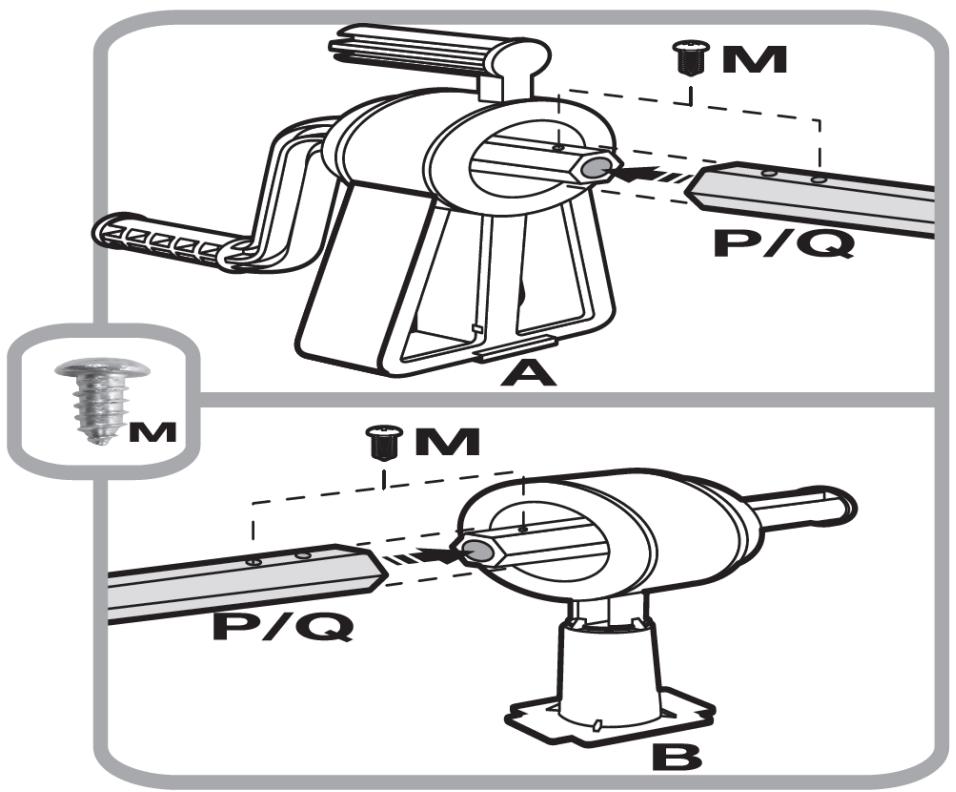
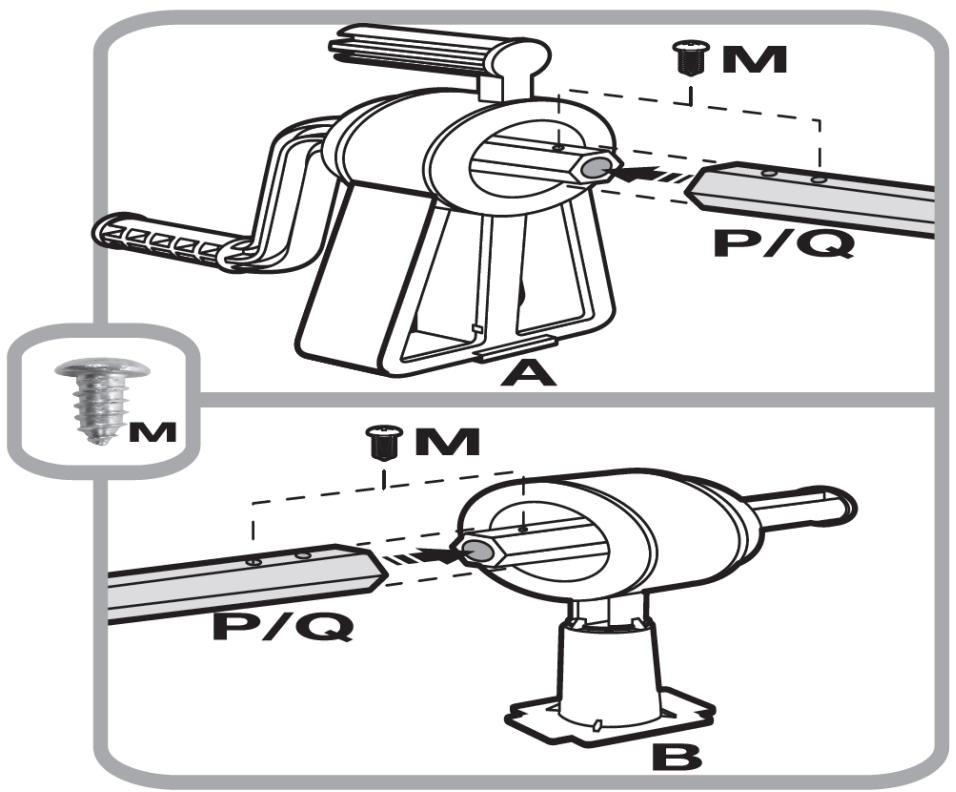
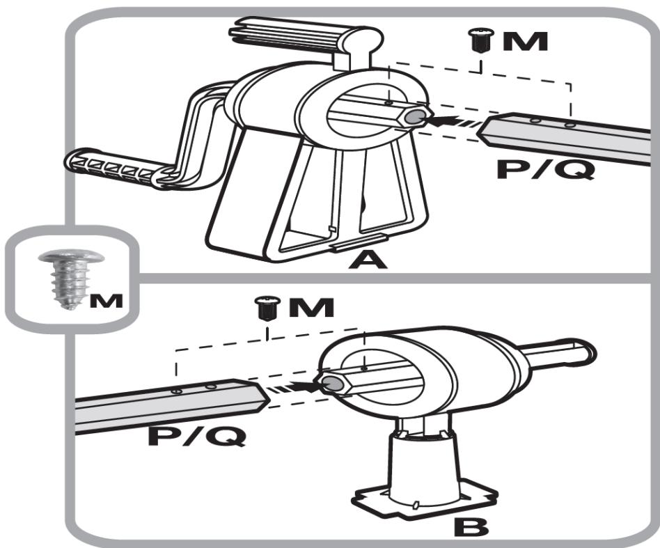
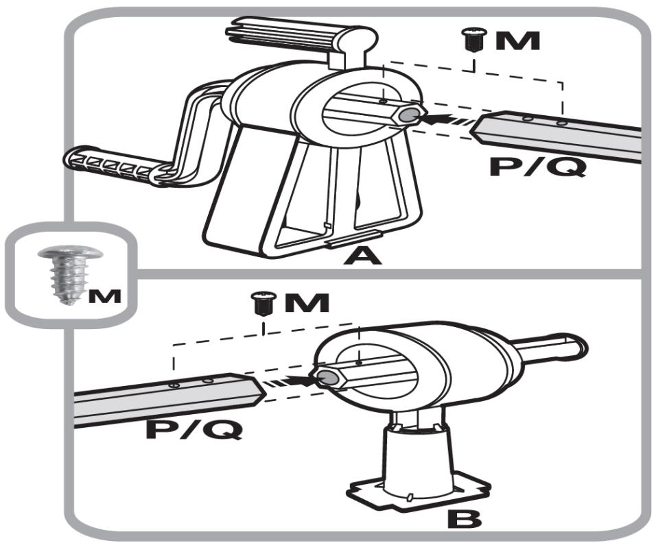
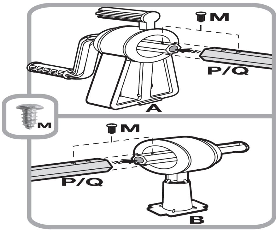
M P/Q A M P/Q B

Abb. 30
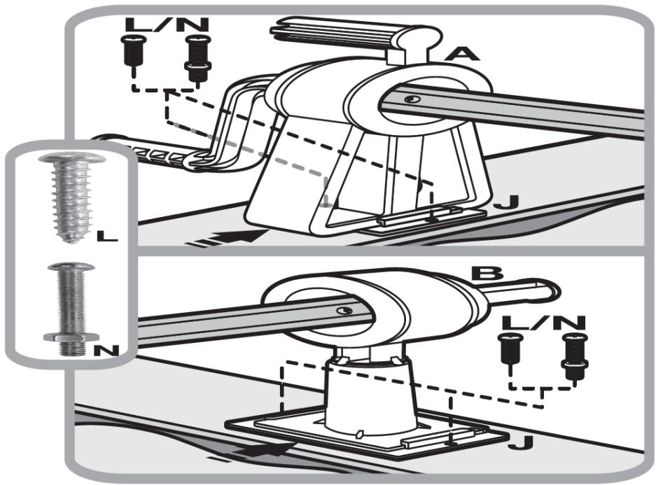
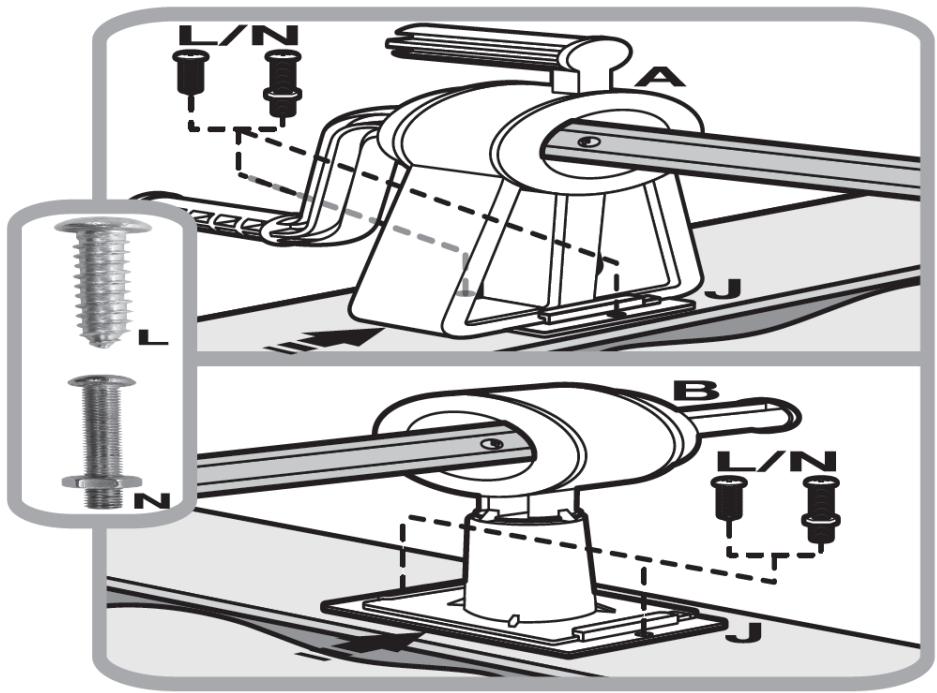
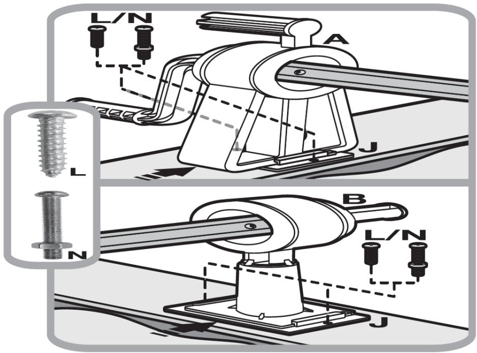
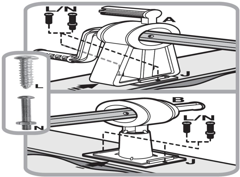
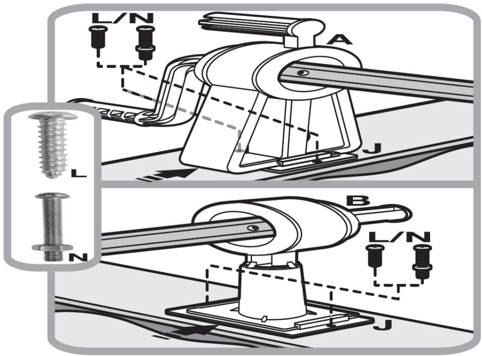
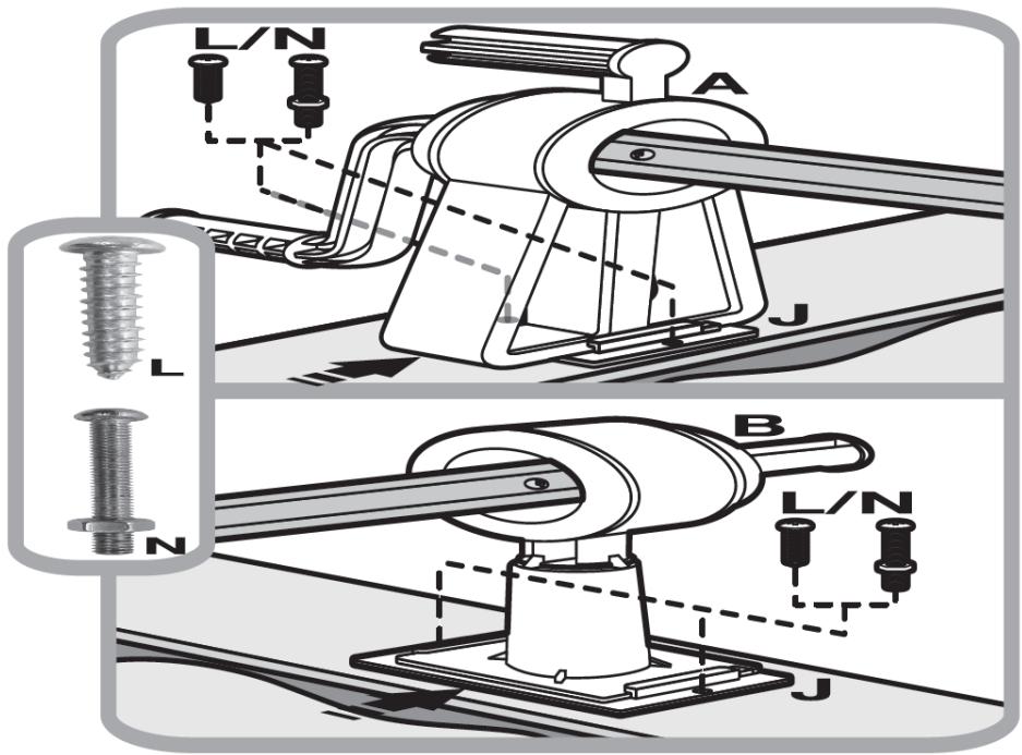
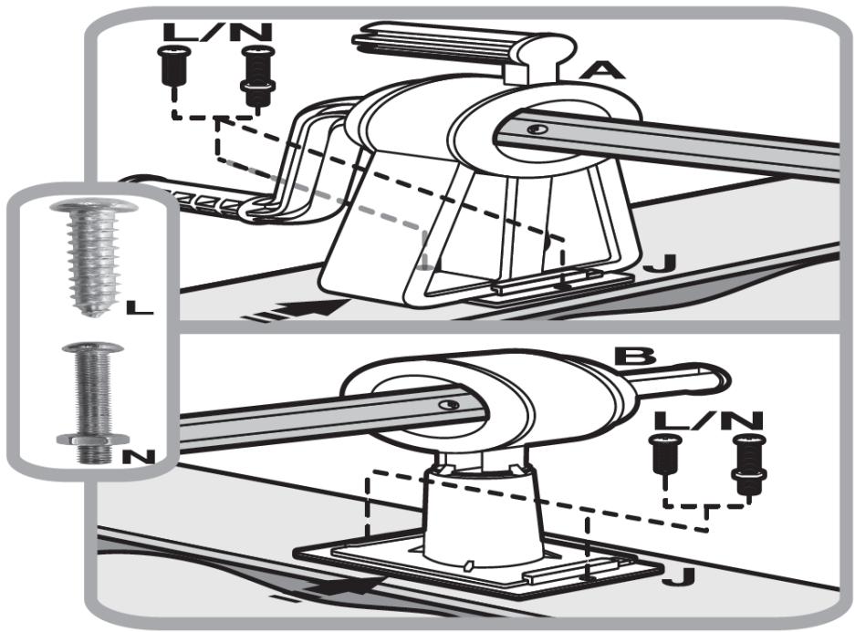
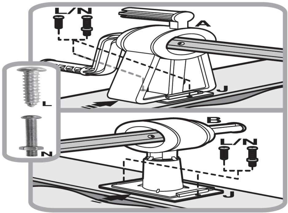
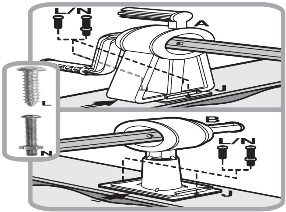
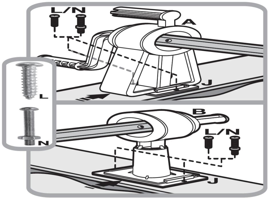
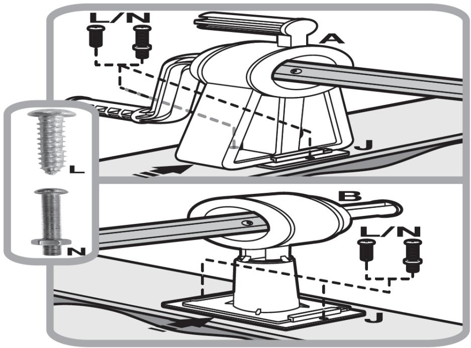
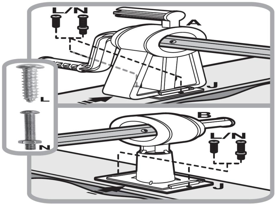
L/N A J L B L/N N J

Abb. 31.
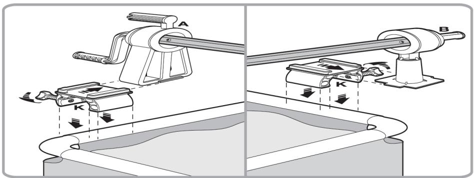
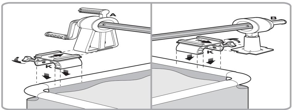
Technical diagram illustrating mechanical assembly with labeled components A and B, showing directional arrows and component movement.

Abb. 32.
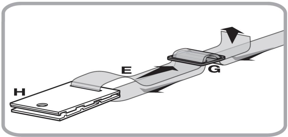
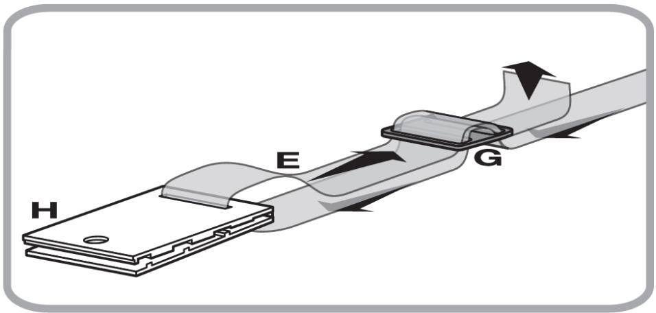
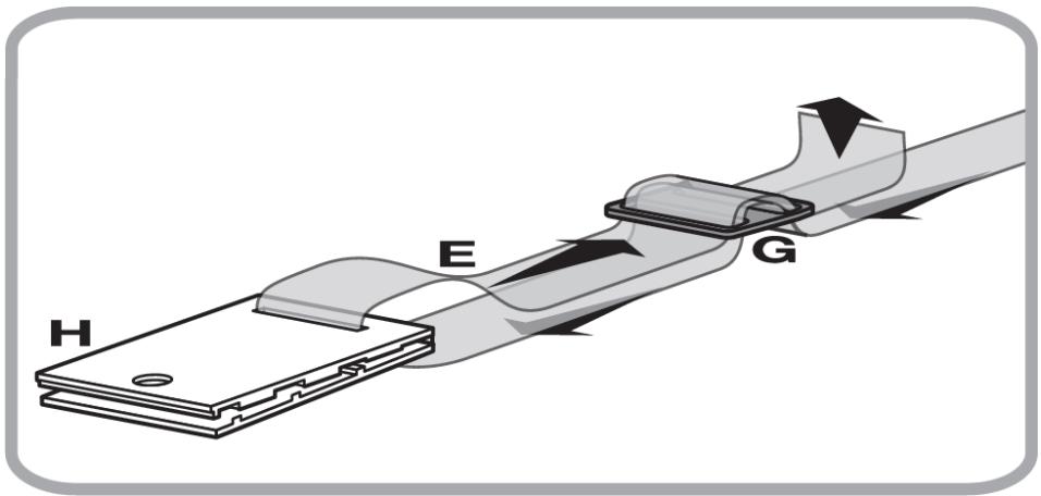
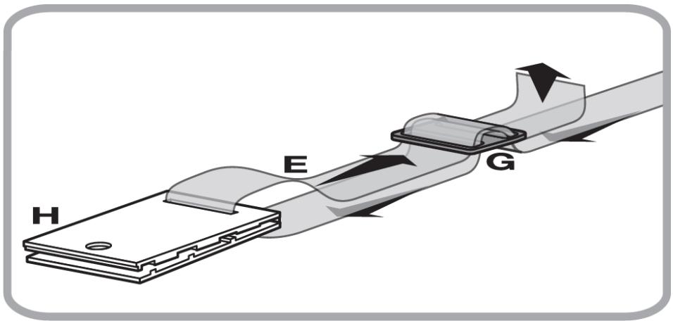
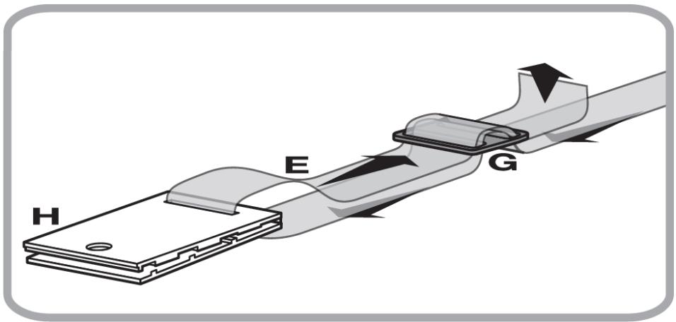
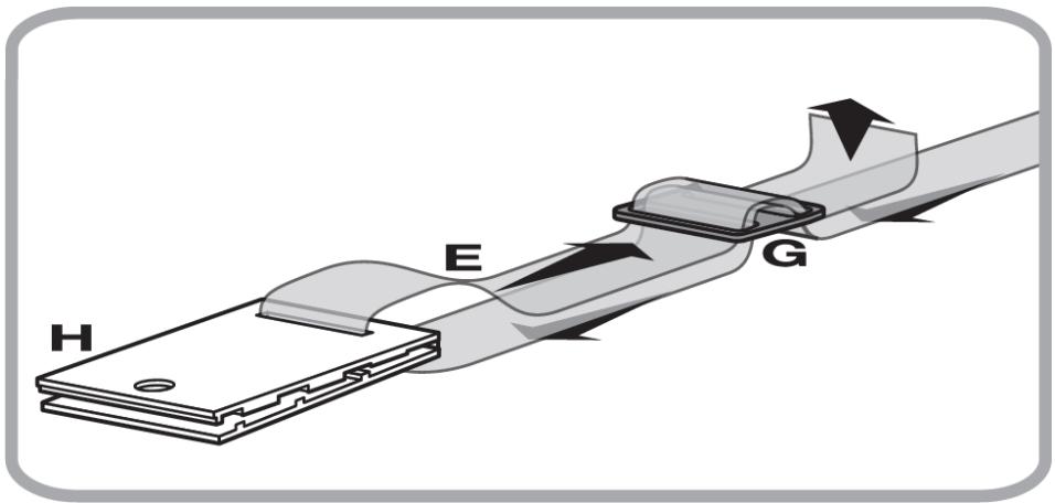
H E G

Abb. 33
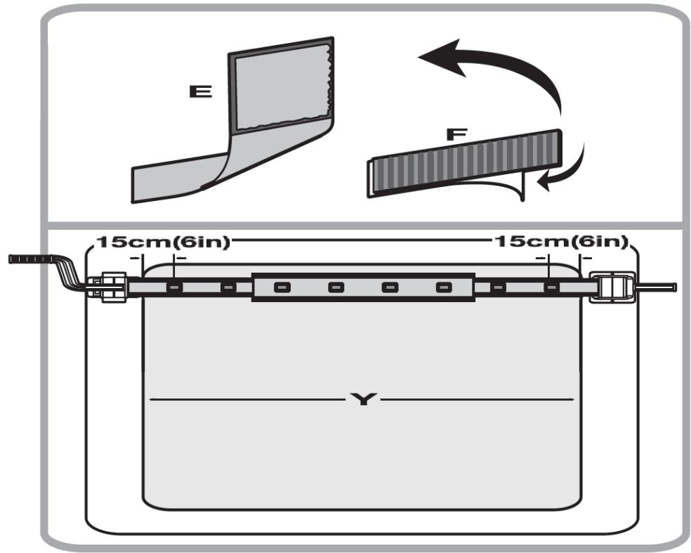
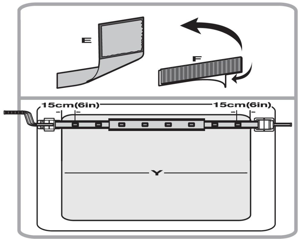
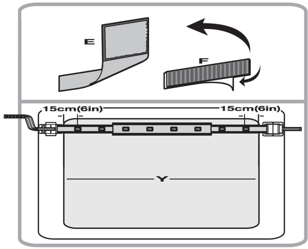
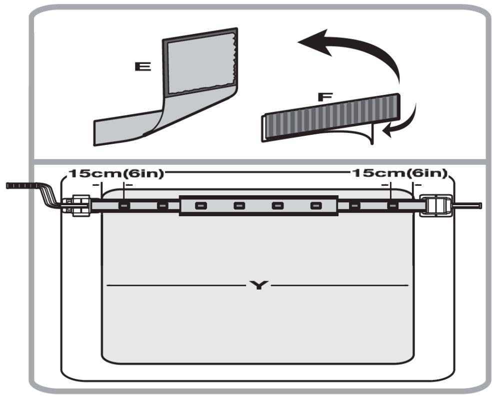
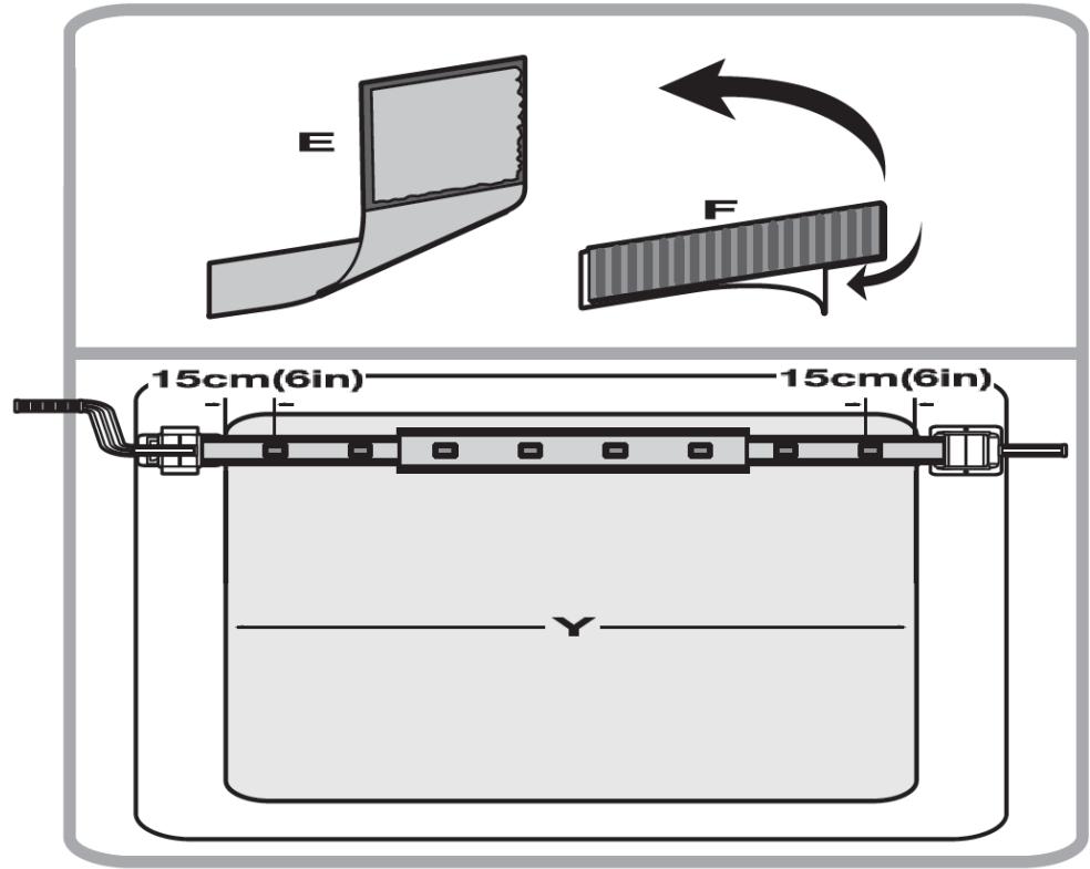
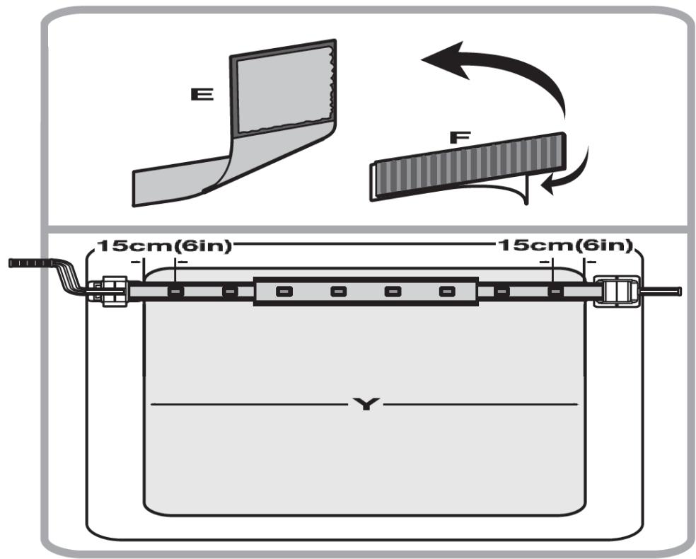
E F 15cm(6in) 15cm(6in) Y

Abb. 34.
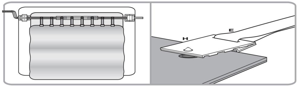
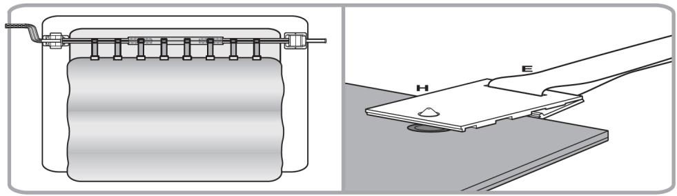
Technical diagram of a mechanical device with two views: one showing a spring-loaded mechanism and the other showing a flat plate with labeled parts H and E (no text or symbols beyond labels)

Abb. 35.
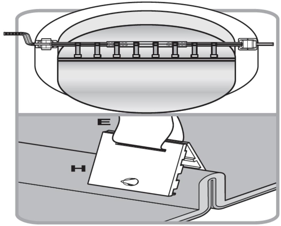
Technical diagram of a mechanical device with labeled components (E and H), showing internal structure and wiring (no text or symbols beyond labels)

Abb. 36.
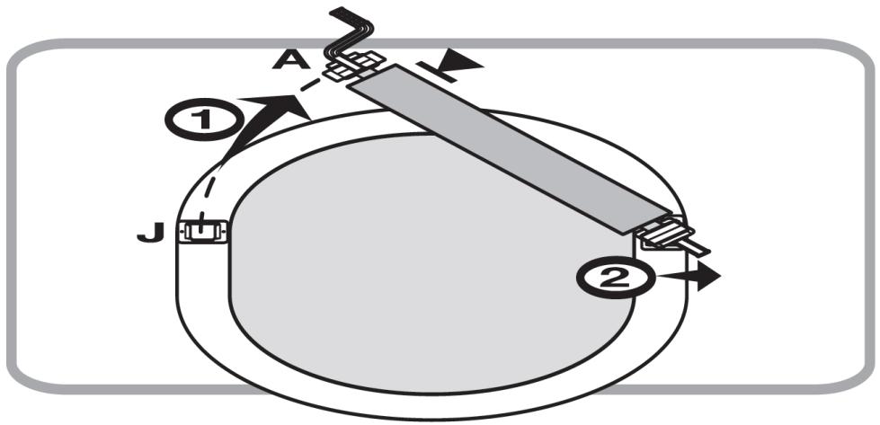
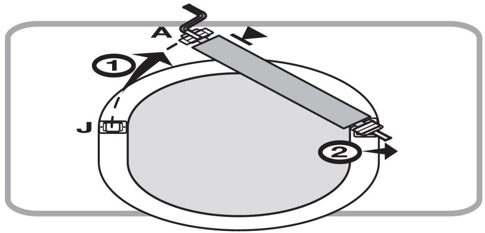
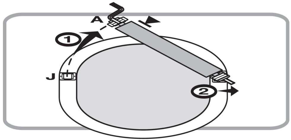
A ① J ②

Uniprodo UNI_POOL_REEL_585 - UNI_POOL_REEL_585 - 52

This User Manual has been translated using machine translation. We have made every effort to ensure the translation is accurate, but please note that automated translations are not perfect and are not meant to replace human translators. The official version of the User Manual is in English. Any differences between the translated version and the original English are not legally binding. If you have any questions about the accuracy of the translation, please refer to the English version, which is the official reference. More language versions are available upon request via info@expondo.com.

Technical data

Parameter descriptionParameter value
Product namePool Reel System
ModelUni_Pool_Reel_520Uni_Pool_Reel_570Uni_Pool_Reel_585
Dimensions [mm]64.8 (from the side of the movable support) / 50 (from the fixed support side) x 56 x 59341.5 from the side of the movable support / 56 from the fixed support side x 51.8 x 642.549.5 from the side with the lever / 35.3 from the side of the lever x 17 x 509
Weight [kg]13.411.35.85
The width of the pool [m]4.22÷5.253.01÷5.741.22÷6
Length of individual roller tubes [cm]140150105 (7 pcs.)32 (1 pcs.)
The diameter of the tube [cm]7.6 / 8.17.6 / 8.142 / 37
Wheel size [cm]19.519.5-
Maximum load [kg]606030.15

1. General description

The user manual is designed to assist in the safe and trouble-free use of the device. The product is designed and manufactured in accordance with strict technical guidelines, using state-of-the-art technologies and components. Additionally, it is produced in compliance with the most stringent quality standards.

DO NOT USE THE DEVICE UNLESS YOU HAVE THOROUGHLY READ AND UNDERSTOOD THIS USER MANUAL

To increase the product life of the device and to ensure a trouble-free operation, use it in accordance with this user manual and regularly perform the maintenance tasks. The technical data and specifications in this user manual are up to date. The manufacturer reserves the right to make changes associated with quality improvement.

Legend

Uniprodo UNI_POOL_REEL_585 - Legend - 1

Read instructions before use.

Uniprodo UNI_POOL_REEL_585 - Legend - 2

WARNING! or CAUTION! or REMEMBER! Applicable to the given situation. (general warning sign)

Uniprodo UNI_POOL_REEL_585 - Legend - 3

PLEASE NOTE! Drawings in this manual are for illustration purposes only and in some details it may differ from the actual product.

2. Usage safety

!ATTENTION! Read all safety warnings and all instructions. Failure to follow the warnings and instructions may result in serious injury or even death.

Whenever "device" or "product" are used in the warnings and instructions, it shall mean:

Pool Reel System.

a) In case of doubt whether the product operates correctly or finding damage please contact the service centre of the manufacturer.
b) Only the service centre of the manufacturer can make repairs of the product Do not attempt to make repairs yourself!
c) Please keep this manual available for future reference. If this device is passed on to third parties, the manual must be passed on with it.
d) Do not use the device when tired, ill or under the influence of alcohol, narcotics or medication which can significantly impair the ability to operate the device.
e) The device is not designed to be handled by persons (including children) with limited mental and sensory functions or persons lacking relevant experience and/or knowledge unless they are supervised by a person responsible for their safety or they have received instructions on how to operate the device.
f) Do not overestimate your abilities. When using the device keep your balance and remain stable at all times. This will ensure better control over the device in unexpected situations.
g) The device is not a toy. Children should be supervised so that they will not play with the device.
h) Maintain the device in a good technical state. Before each use check for general damage and especially check for cracked parts or elements and for any other conditions which may impact the safe operation of the device. If damage is discovered, hand over the device for repair before use.
i) Device repair or maintenance should be carried out by qualified persons, only using original spare parts. This will ensure safe use.
j) When transporting and handling the device between the warehouse and the destination, take into account the occupational health and safety principles for manual transport operations which apply in the country where the device will be used.
k) Before unfolding the solar film, make sure that there are no people or animals in the pool.
I) It is forbidden to stay, lie down, stand on or pull the solar film when it is being wound up or unwound. It may damage the product.
m) While rolling or unrolling, do not jerk the wheel which drives the roller.
n) It is recommended to not use excessive force while winding the pool cover. If blockages occur, they must be removed first.

3. Use guidelines

The product is designed for rolling, unrolling and storing the solar film.

The user is liable for any damage resulting from nonintended use of the device.

3.1. Device description

Please note: This product's view can be found on the last page of the operating instructions.

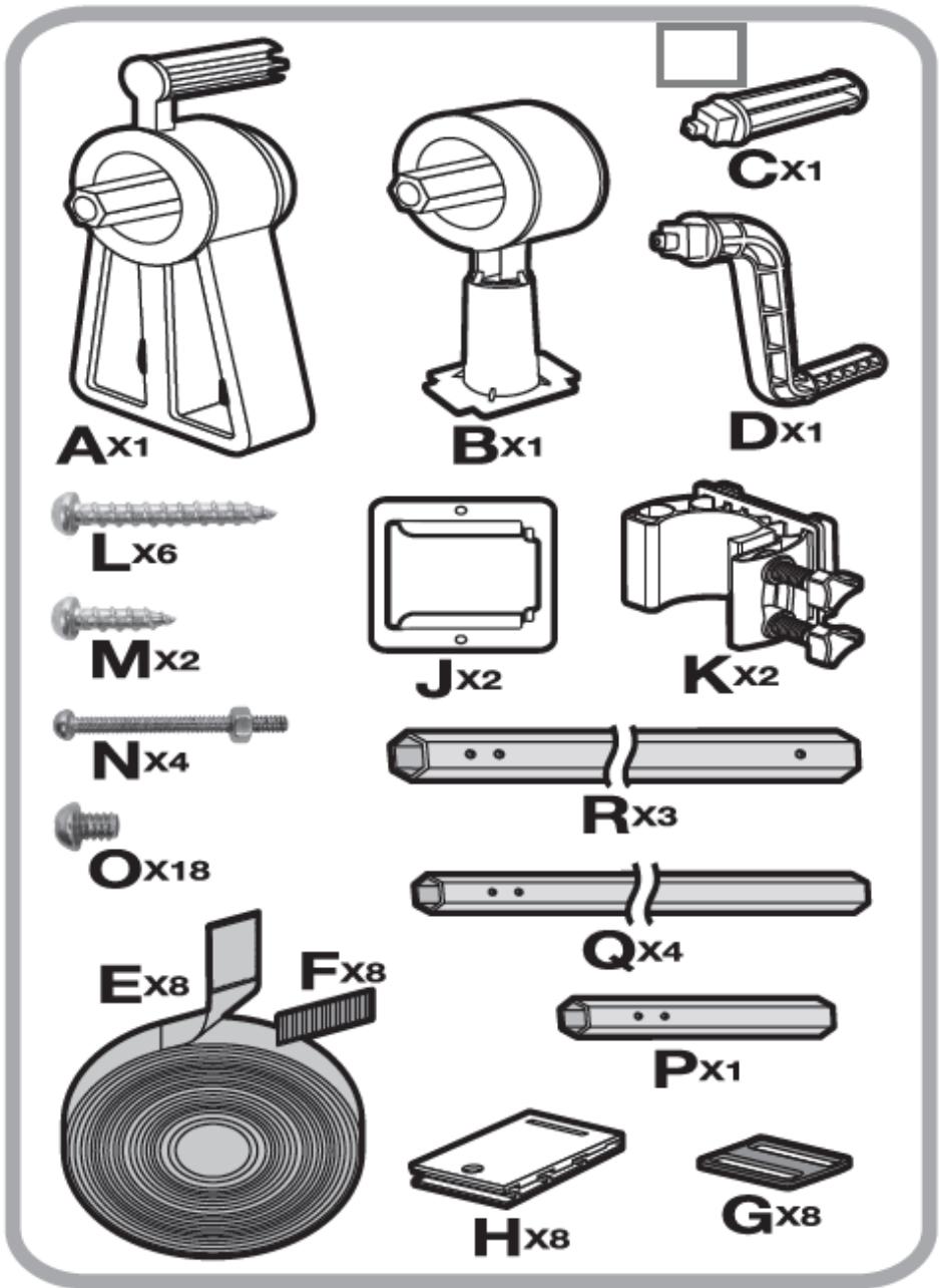
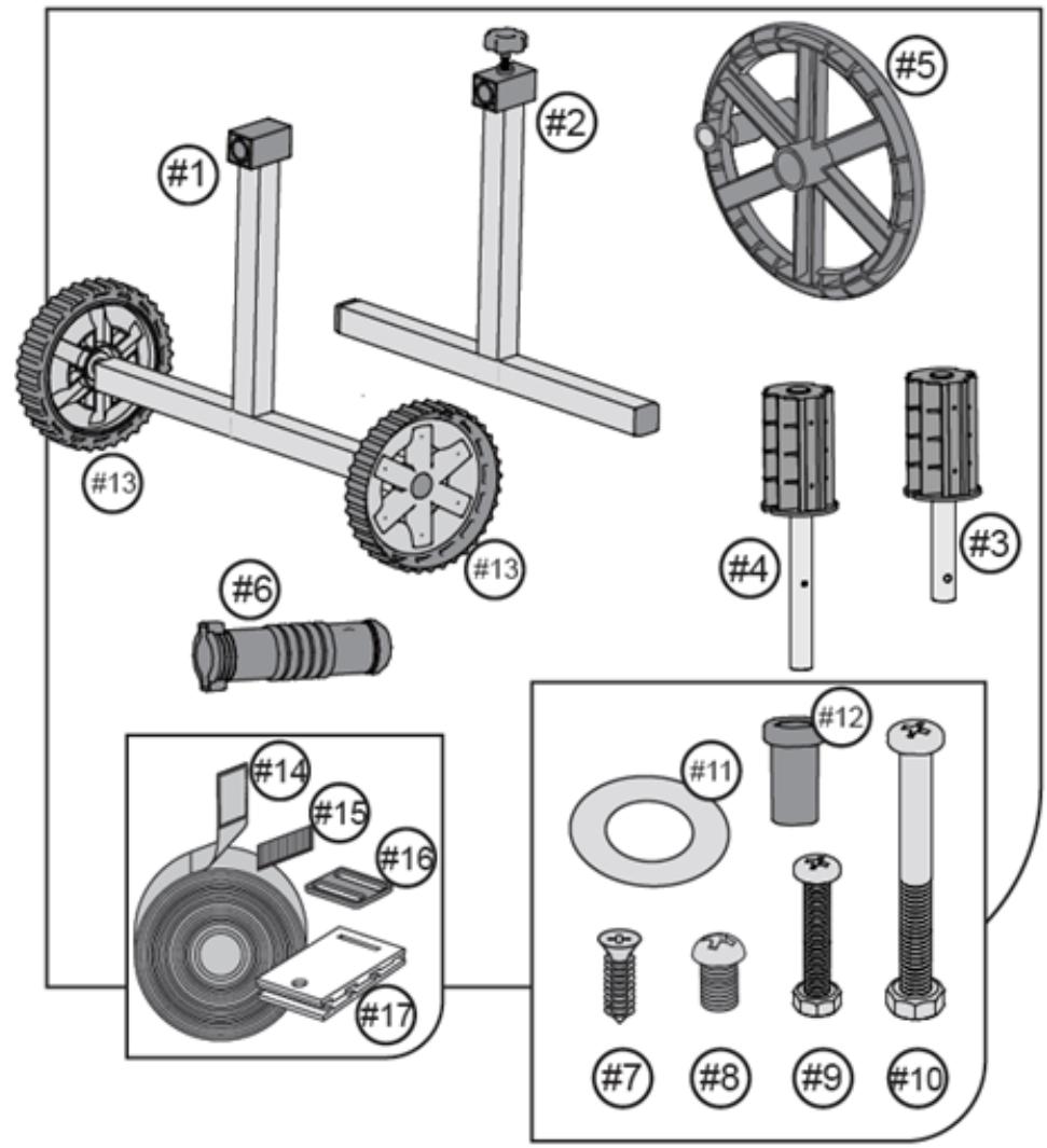
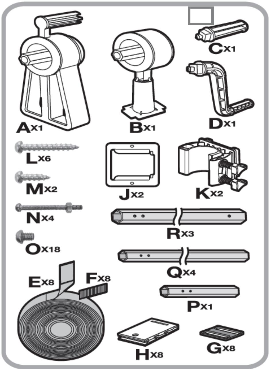
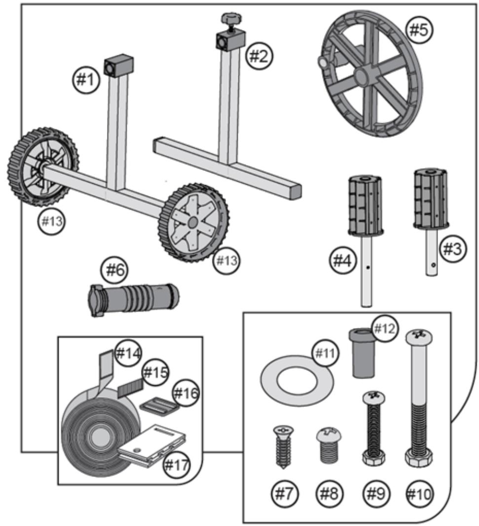
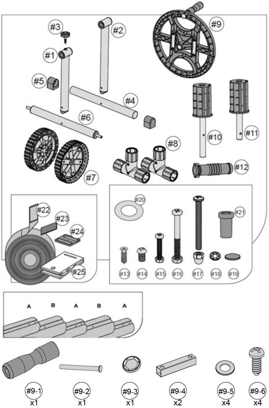
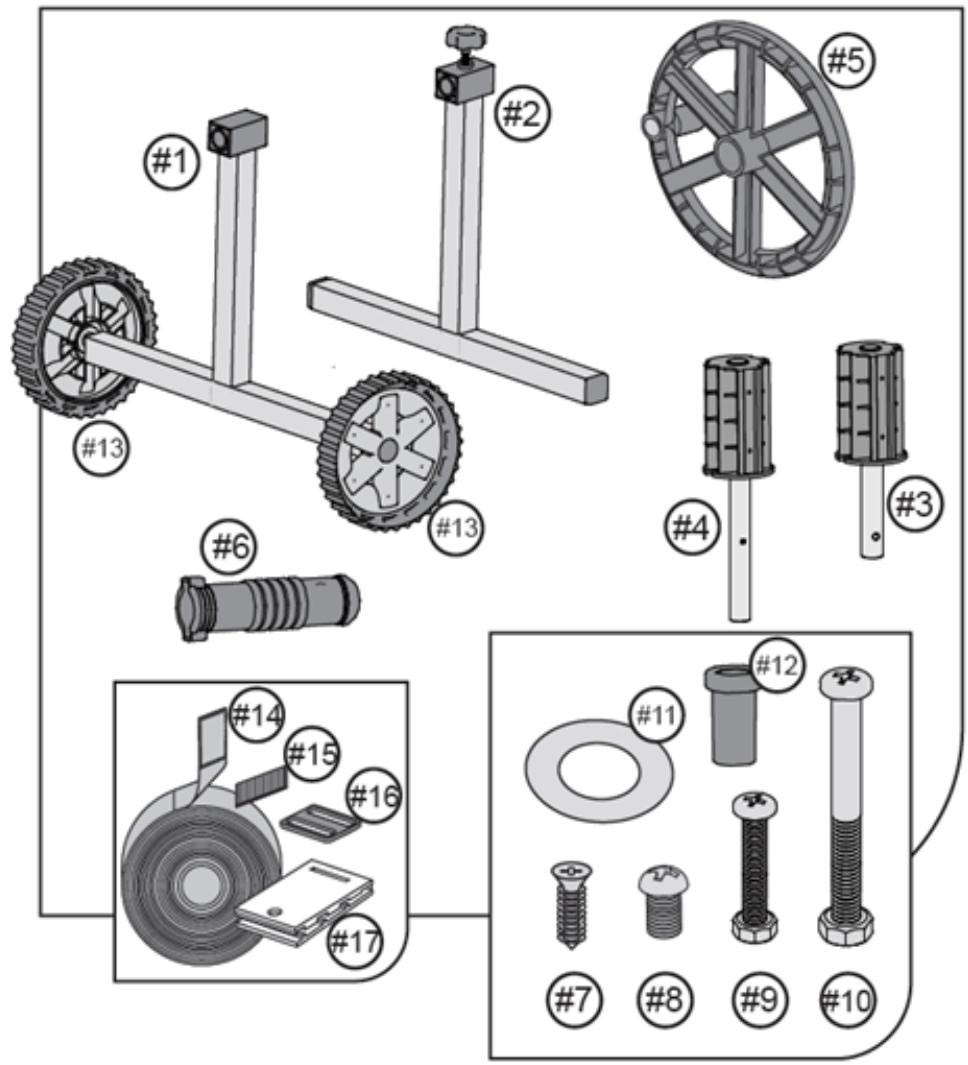
UNI_POOL_REEL_520 (See fig. 1)UNI_POOL_REEL_570 (See fig. 2)UNI_POOL_REEL_585 (See fig. 3)
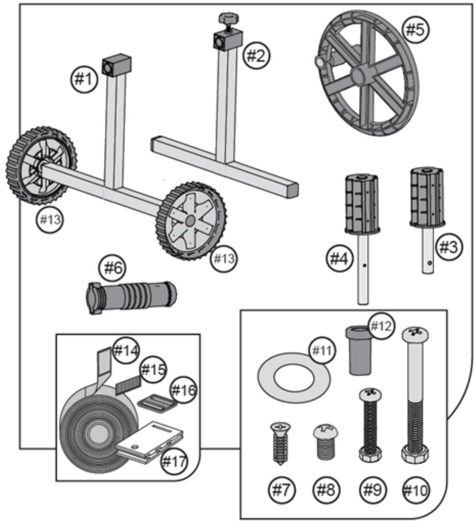
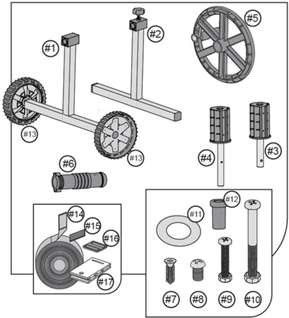
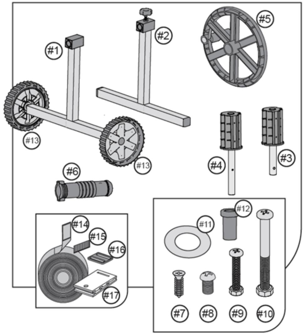
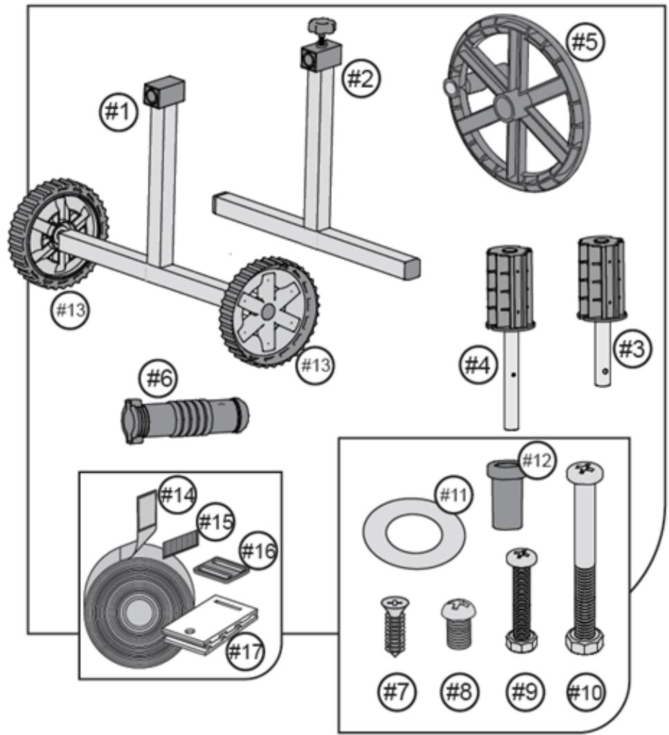
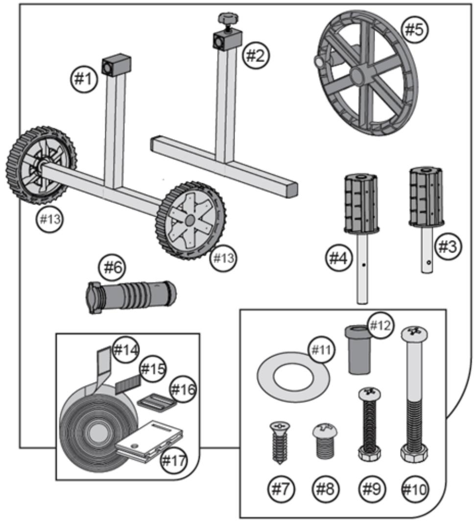
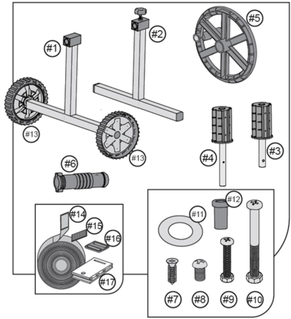
1 - Movable support1 - Movable supportA - Roller support
2 - Fixed support2 - Fixed supportB - Roller support
3 - Clamp screw3 - Roller axleC - Handle
4 - The base of the fixed support4 - Roller axleD - Lever
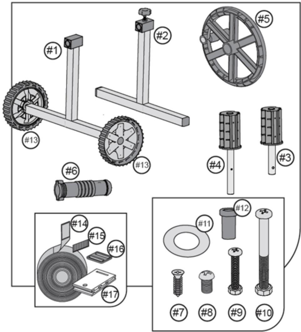
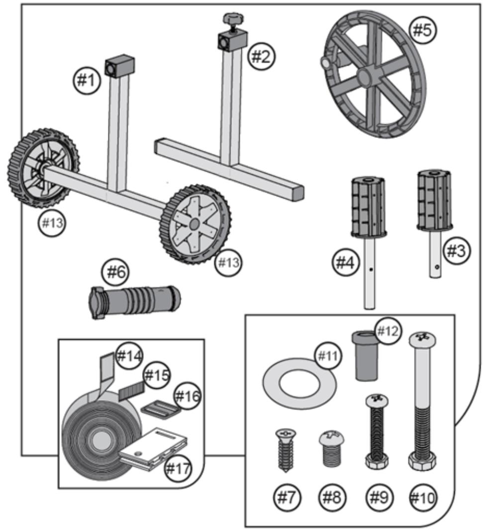
5 - The cap of the support5 - A wheel with a handle to drive the rollerE - A strap with a female Velcro fastener
6 - Base of the movable support6 - HandleF - Male Velcro fastener
7 - Wheels7 - Flat head boltG - Clamp
8 - Connector8 - ScrewH - Clip
9 - Wheel for driving the roller9 - Bolt with nutJ - Support base (for mounting on a flat pool edge)
9-1 - Handle10 - Long bolt with a nutK - Base with handle (for mounting on a tubular frame)
9-2 - Mandrel11 - WasherL - Self-tapping bolt (long)
9-3 - Plug12 - RollM - Self-tapping bolt (short)
9-4 - Safety beams13 - WheelN - Screw and nut
9-5 - Washer14 - Belt with a female Velcro fastenerO - Flat head screw
9-6 - Screw15 - Male Velcro fastenerP - Adapter for hexagonal tube
10 - Roller axle16 - ClampQ - Small hexagonal tube
11 - Roller axle17 - ClipR - Large hexagonal tube
12 - Handle
13 - Bolt
14 - Screw
15 - Screw with nut
16 - Long screw with a nut
17 - Screw with a cap nut
18 - Protective washer
19 - Plug
20 - Washer
21 - Roller guiding the wheel
22 - Strap with a female Velcro fastener
23 - Male Velcro fastener
24 - Clamp
25 - Clip

3.2. Assembly of the device

3.2.1. UNI_POOL_REEL_520

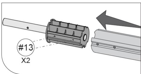
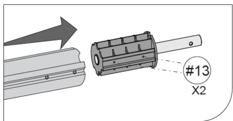
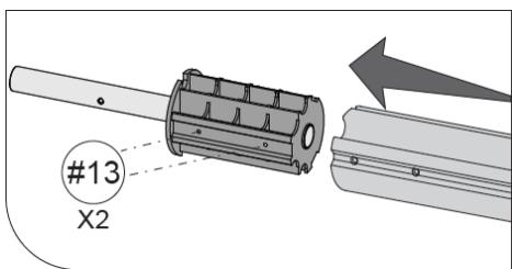
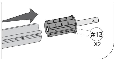
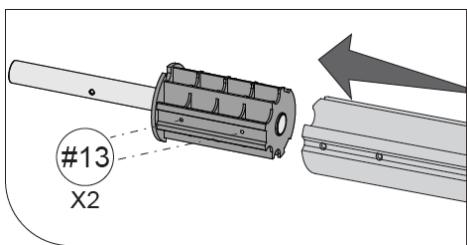
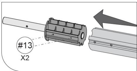
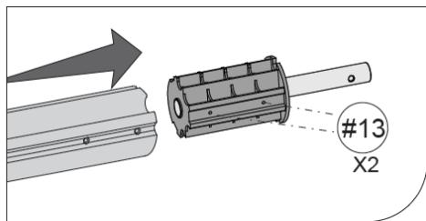
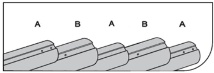
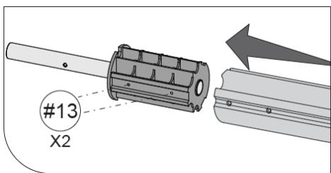
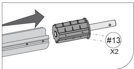
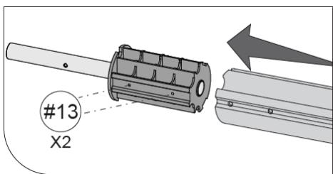
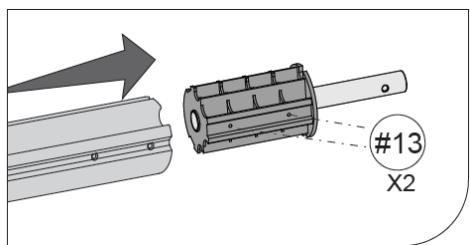
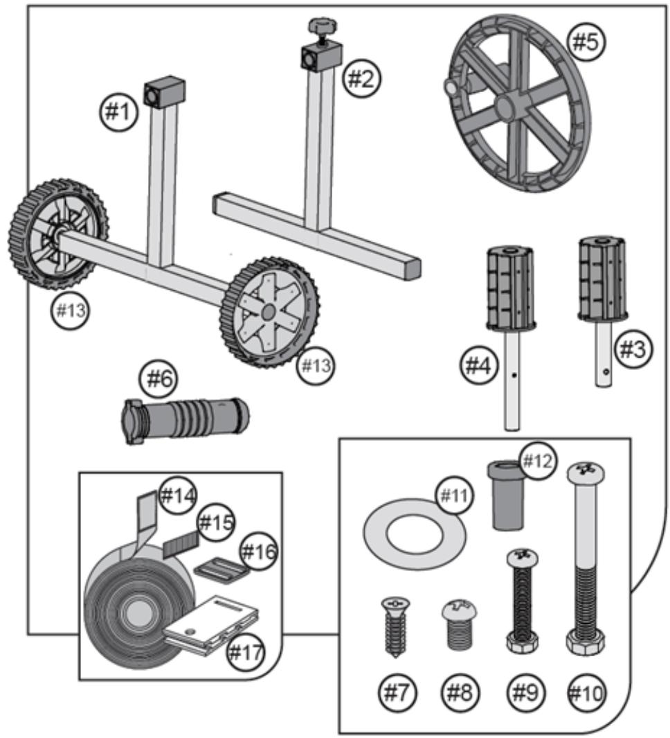
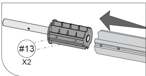
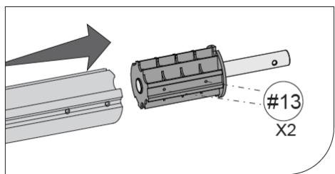
  1. (See fig. 4). Fix the axles of the roller with the screws (13) to the outer tubes type A.
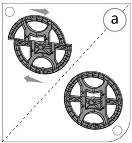
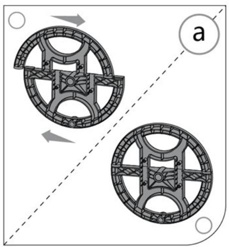
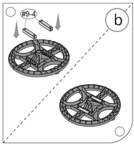
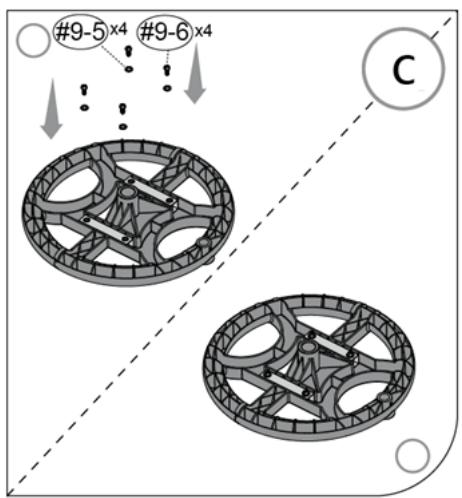
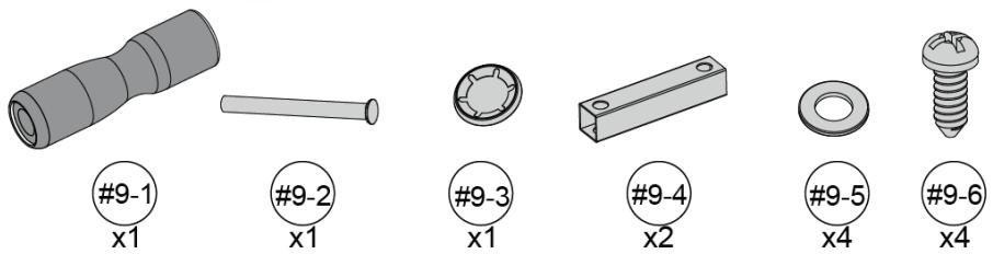
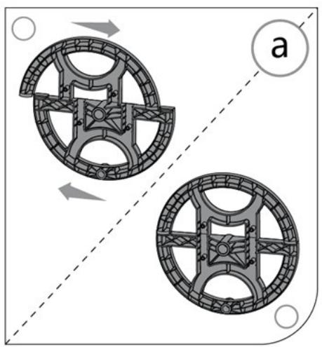
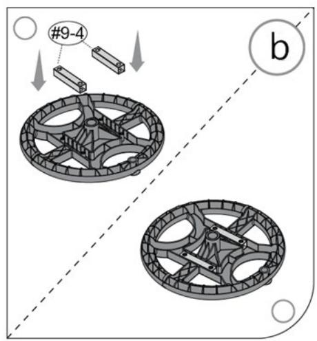
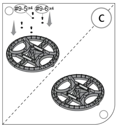
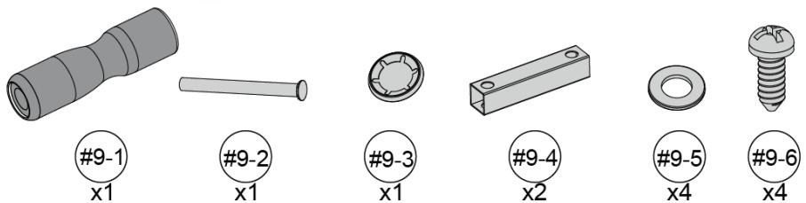
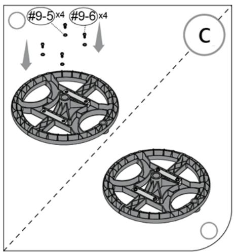
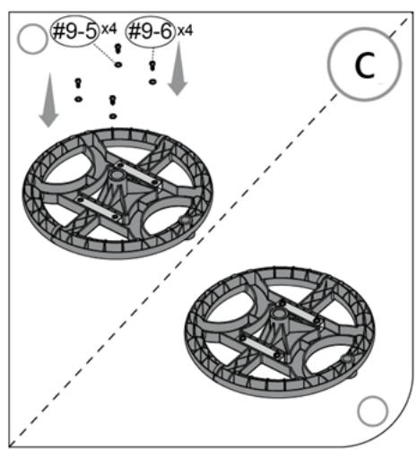
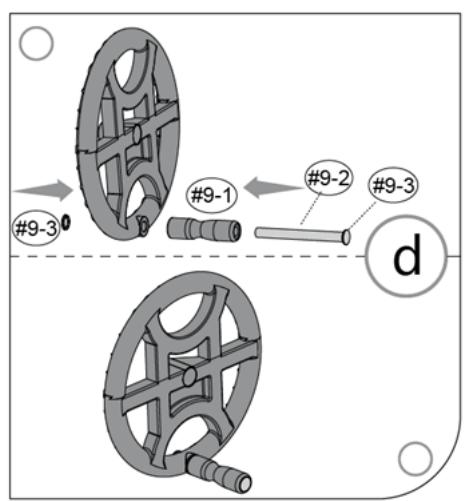
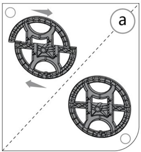
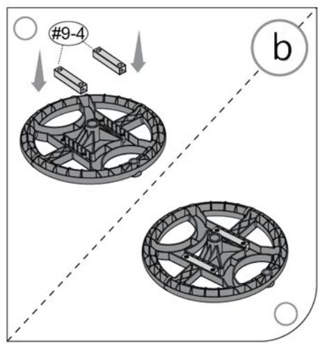
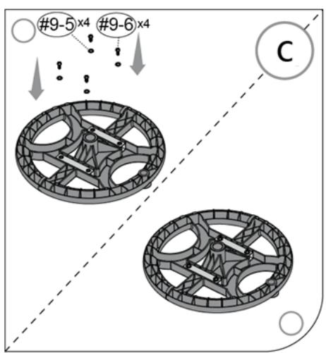
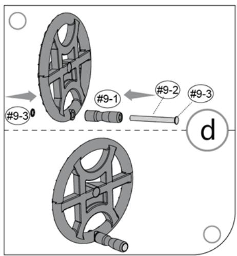
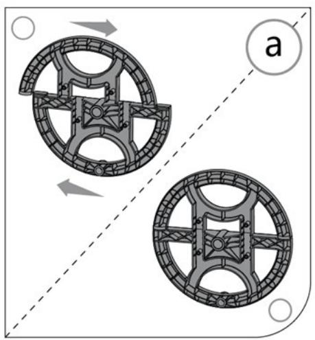
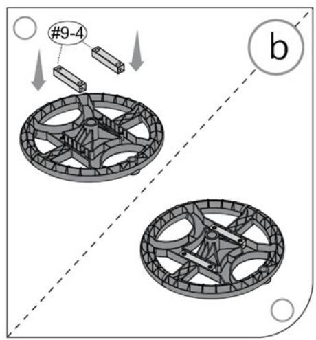
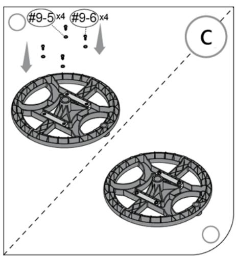
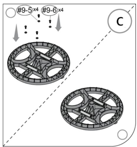
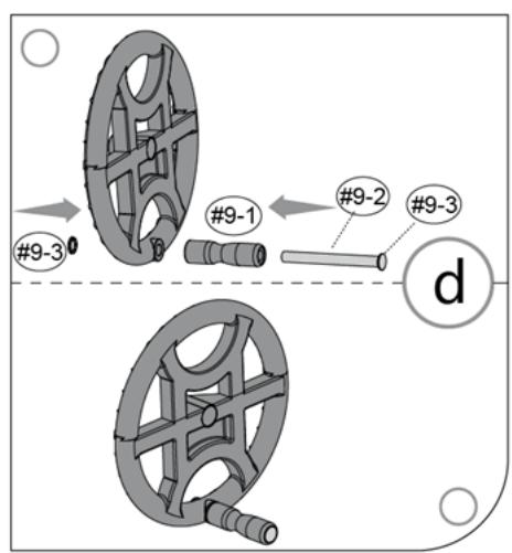
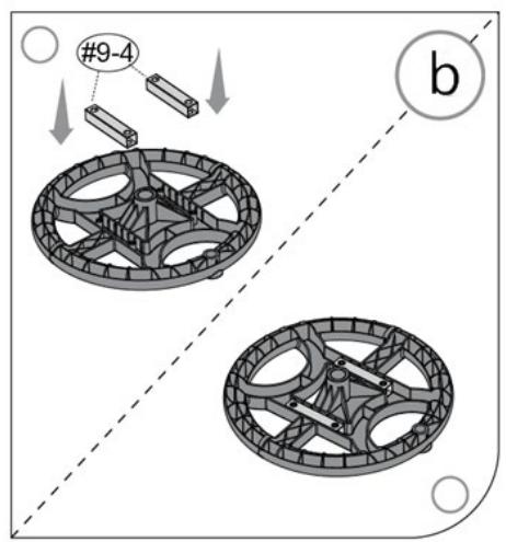
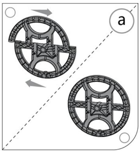
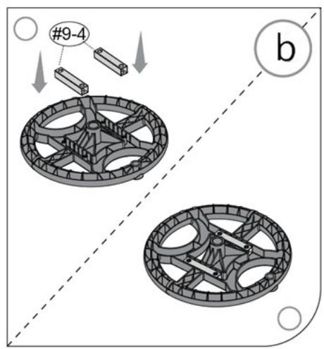
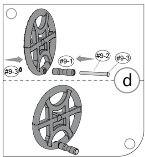
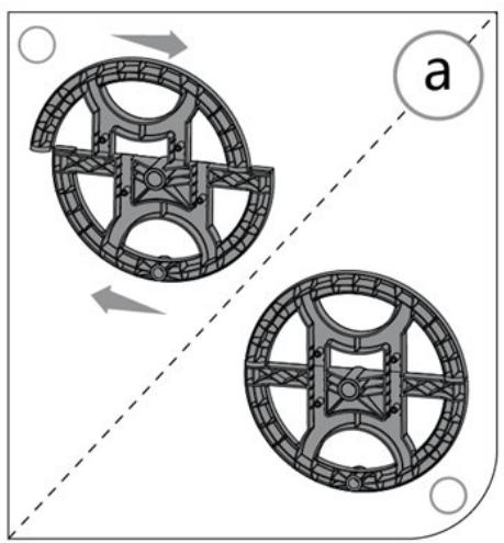
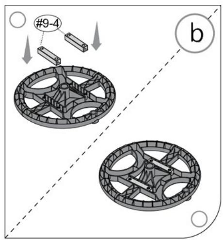
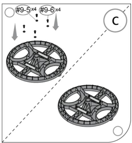
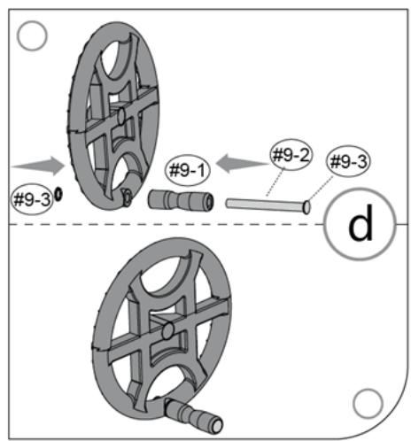
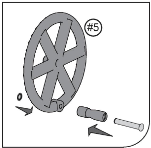
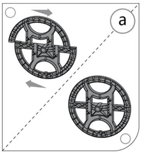
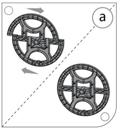
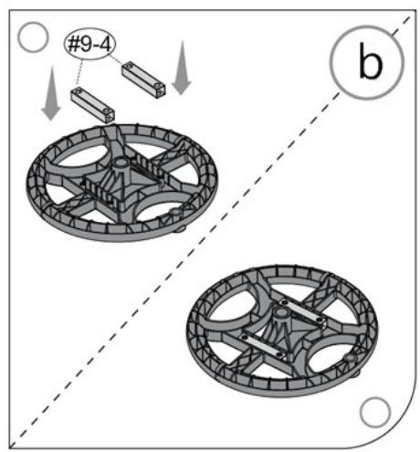
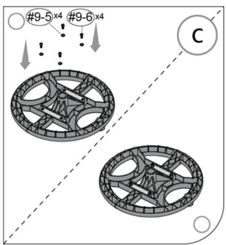
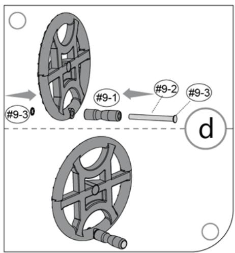
  2. (See fig. 5) Mounting the wheel to drive the roller (9)

a) Push both parts of the wheel together.

b) Insert the safety beams (9-4) between both parts of the wheel (9).
c) Secure the connection with four bolts (9-6) and washers (9-5).
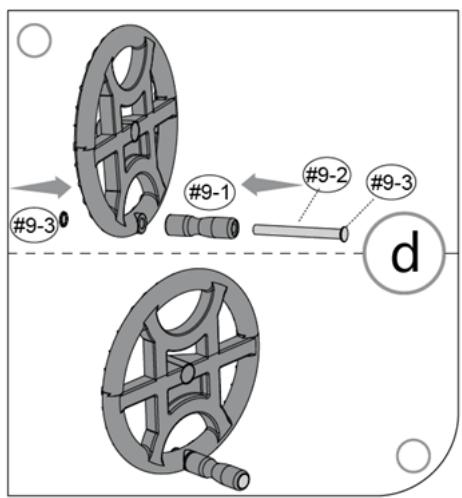
d) Mount the handle (9-1). Insert the mandrel (9-2) into the lever hole, then insert the holder with the spindle into the hole of the wheel driving the roller (9) and secure the connection with the plugs (9-3)

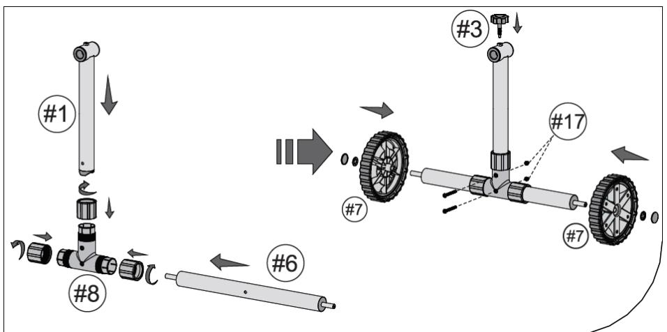
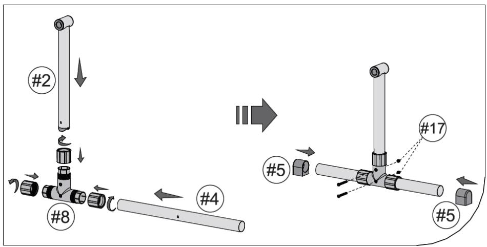
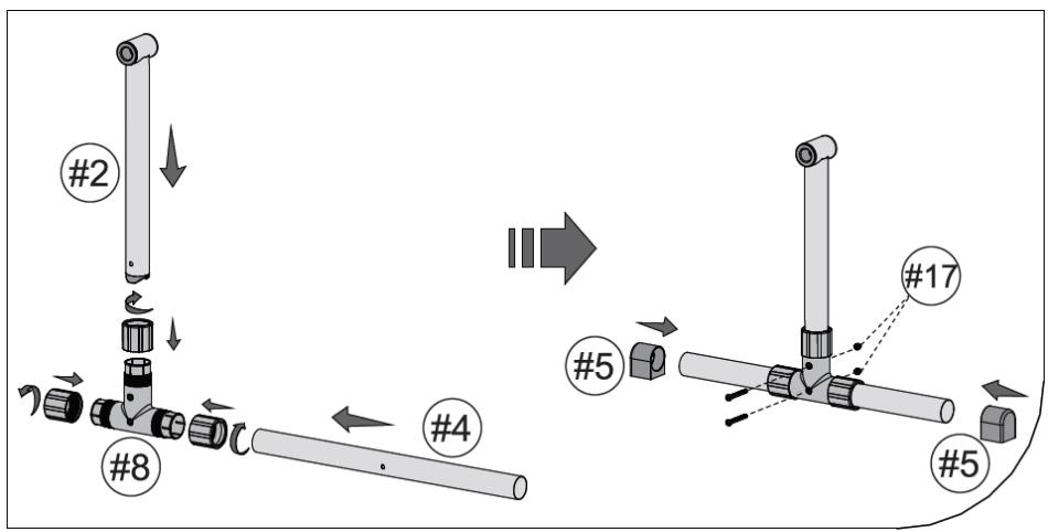
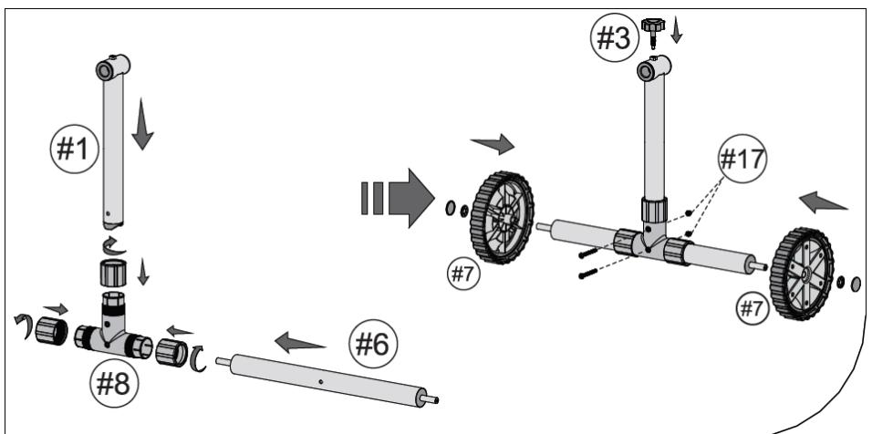
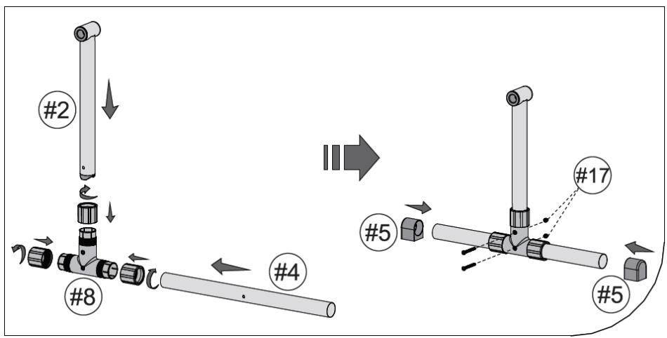
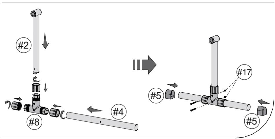
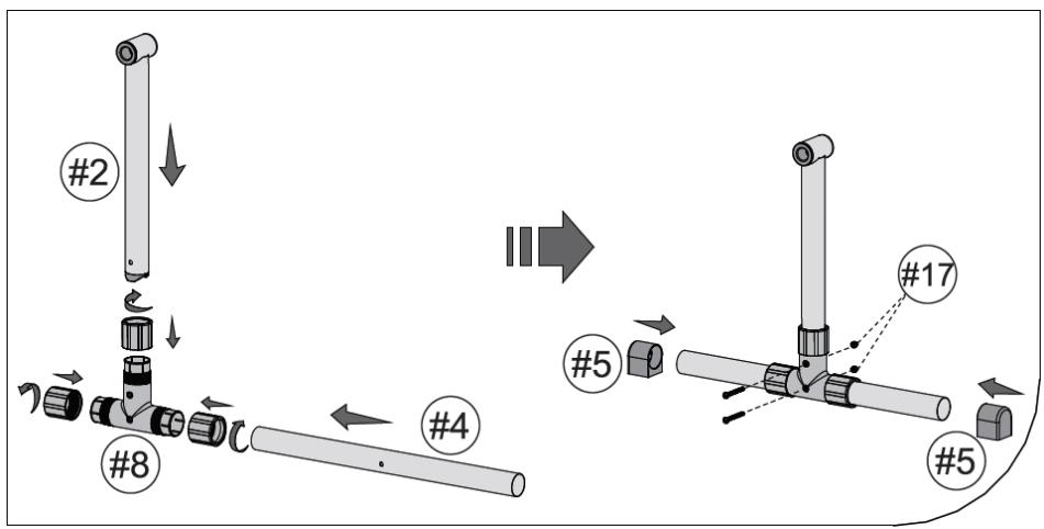
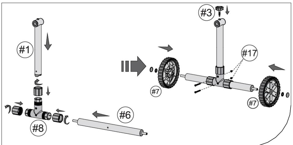
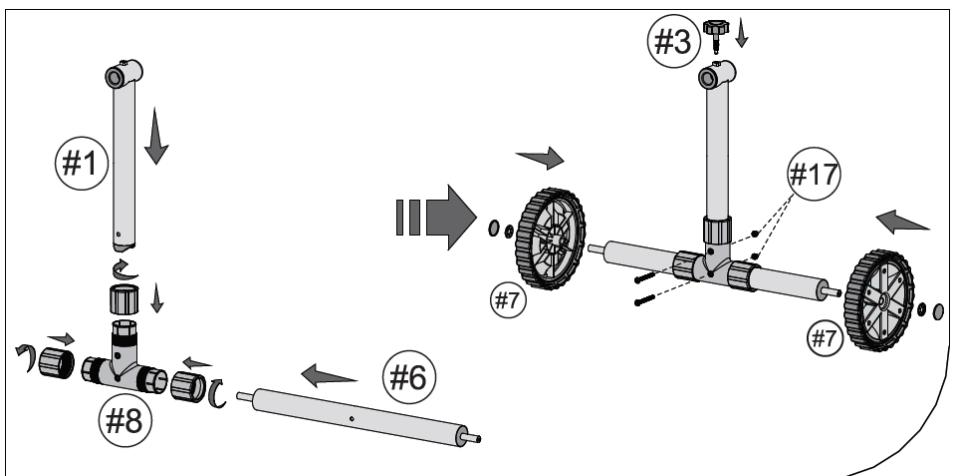
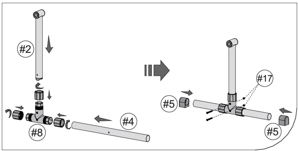
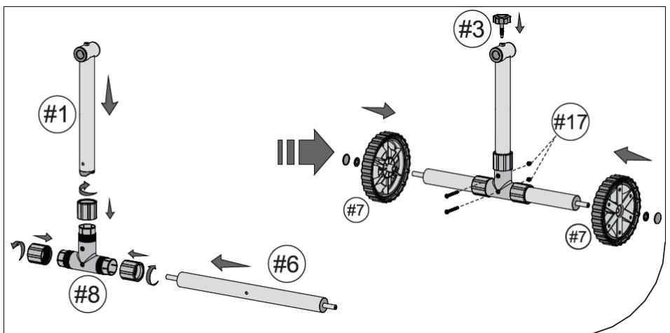
  1. (See fig. 6) Insert the fixed support base (4) and the fixed support (2) into the clamping nuts and then into the connector (8). Tighten the clamping nuts. Secure the connections with screws and cap nuts (17), and then insert the plugs (5) on both ends of the fixed support base (4).

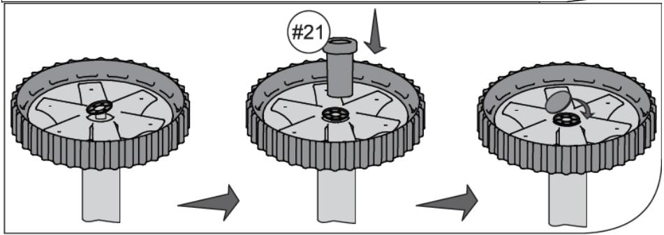
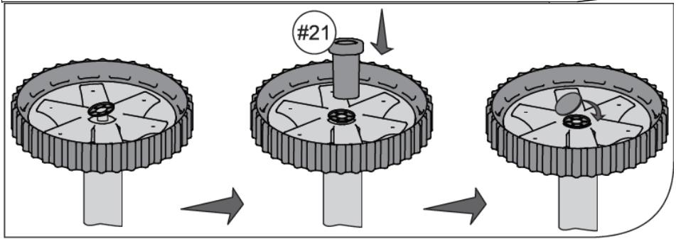
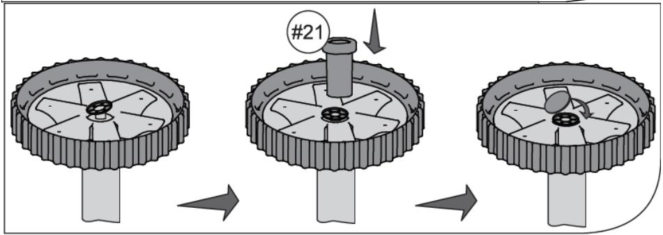
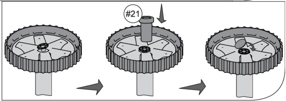
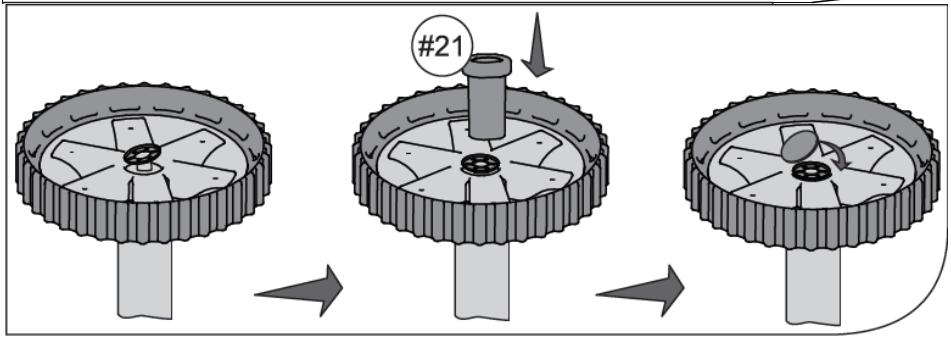
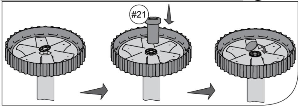
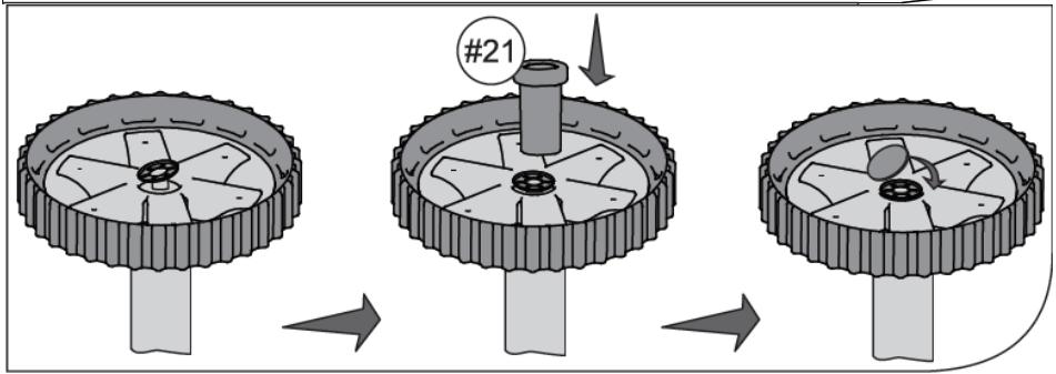
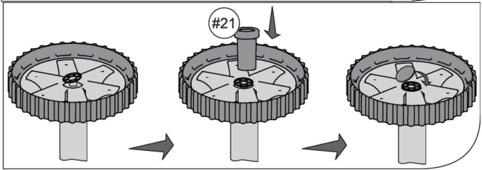
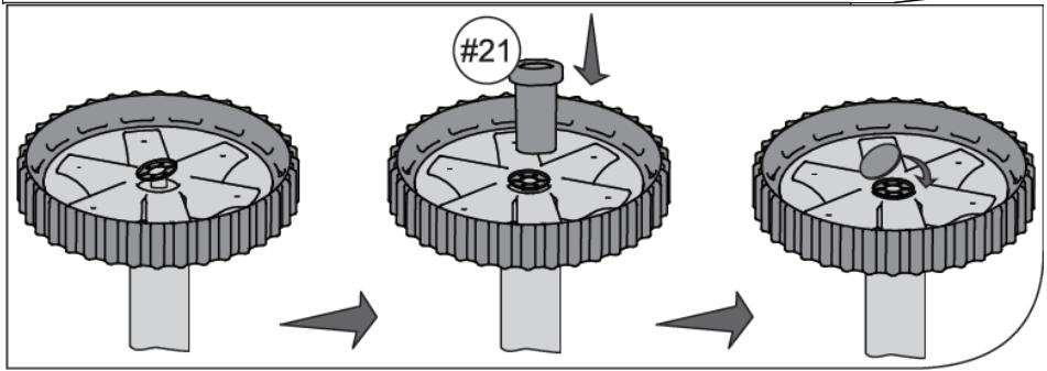
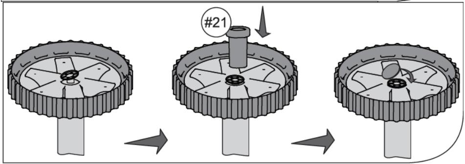
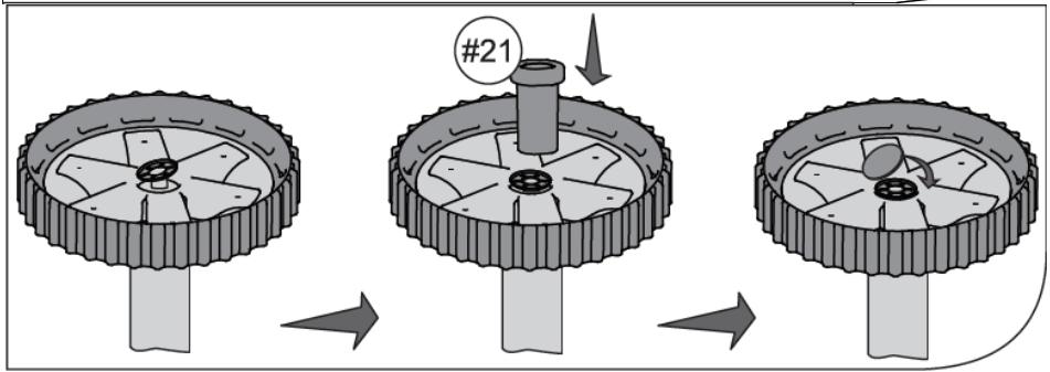
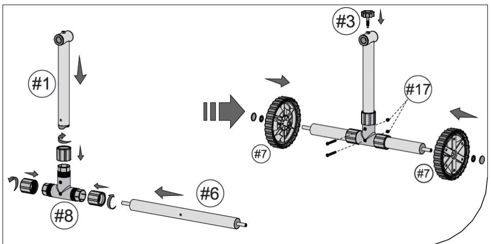
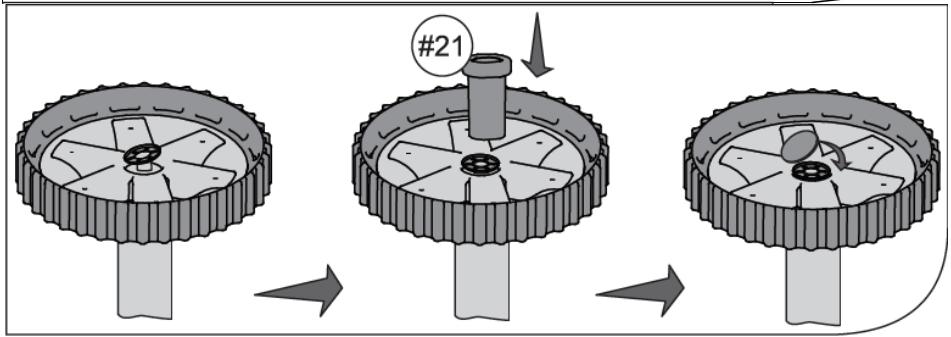
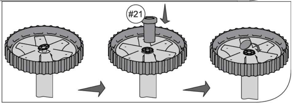
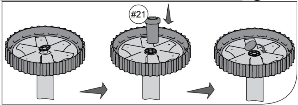
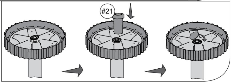
  2. (See fig. 7) Insert the base of the movable support (6) and the movable support (1) with clamping nuts and connector (8). Tighten the clamping nuts. Secure the connections with screws and cap nuts (17), and then slightly tighten the clamp screw (3). Place the wheels (7) on the axles of the movable support (6). Then insert

the guide roll (21) into the centre of the wheels and secure the connection with the locking washer (18) and the plug (19).

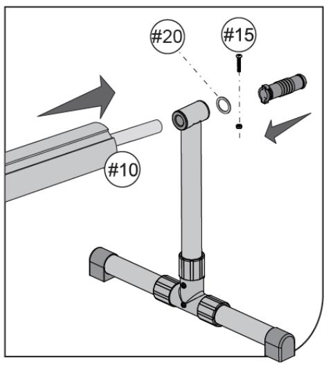
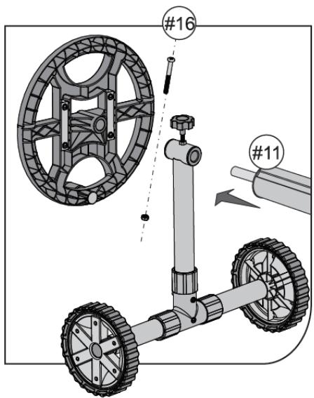
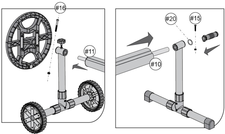
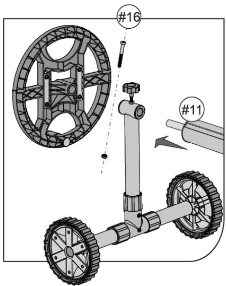
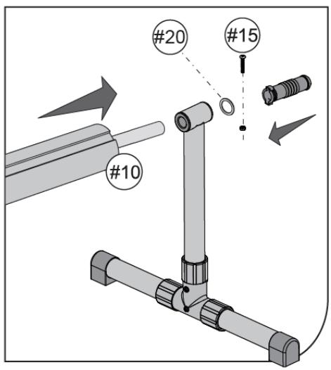
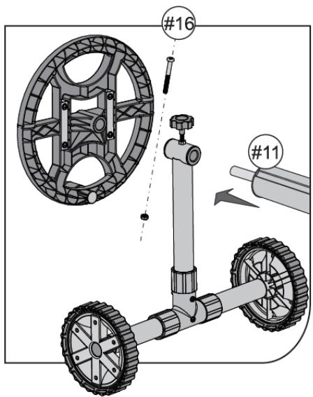
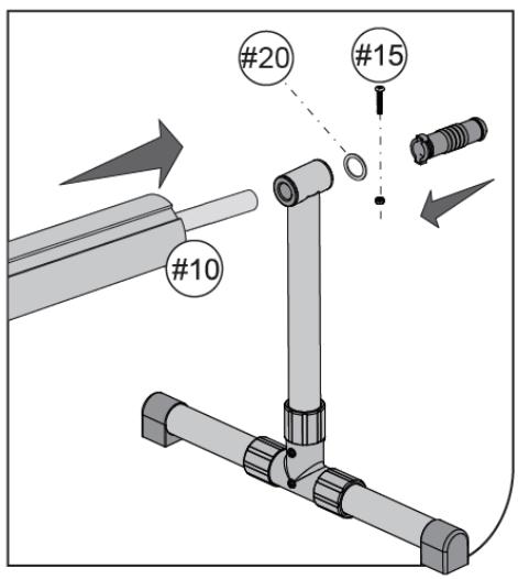
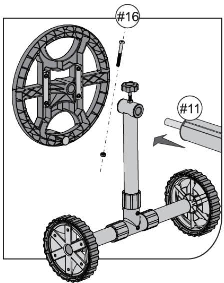
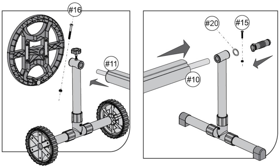
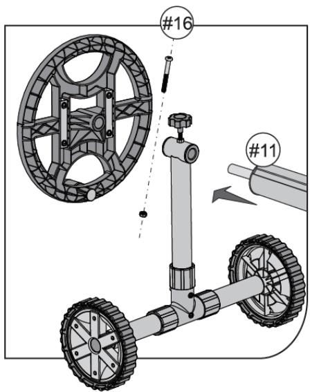
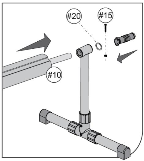
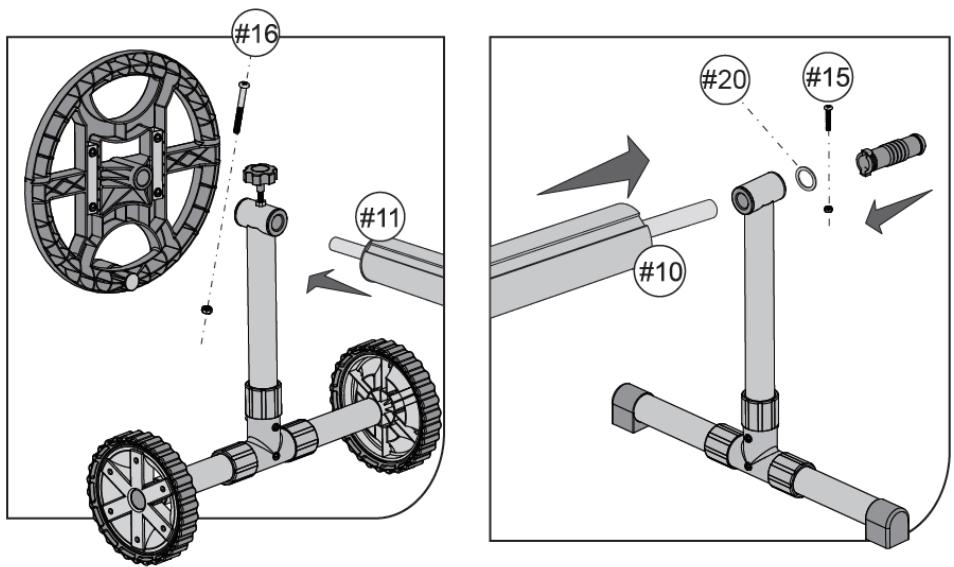
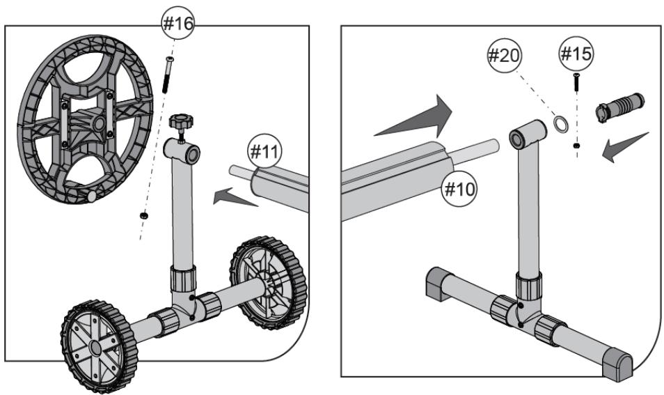
  1. (See fig. 8) Put the roller axle (11) through the movable support (1) and install the wheel on it to drive the roller (16). Secure the connection with the screw and nut (16).

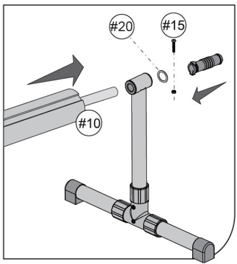
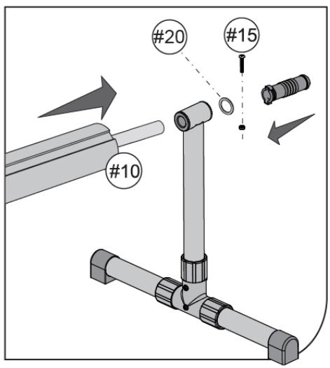
Put the roller axle (10) through the fixed support and mount the washer (20) and the holder (12) on it. Secure the connection with the screw and nut (15).

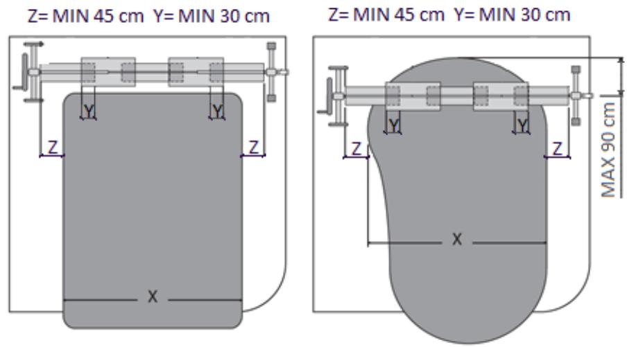
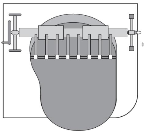
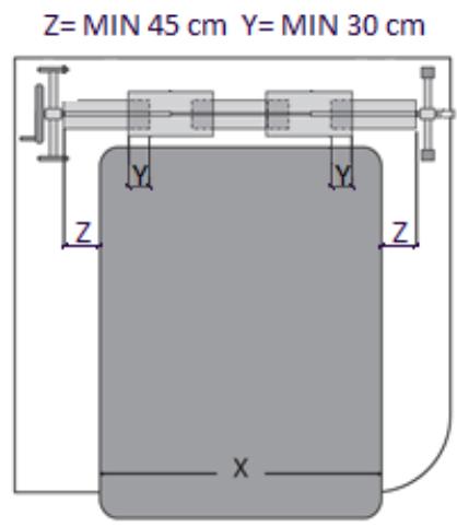
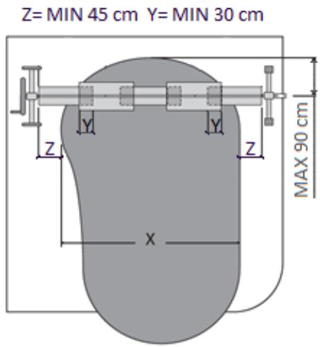
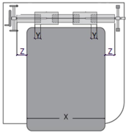
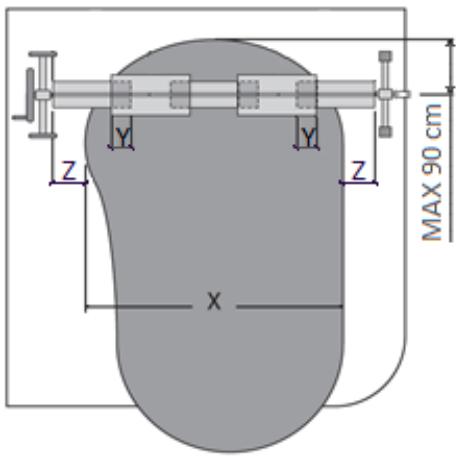
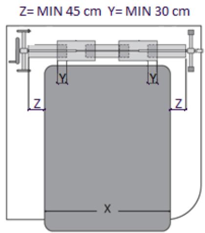
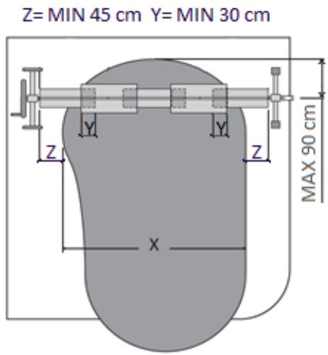
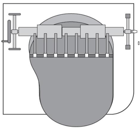
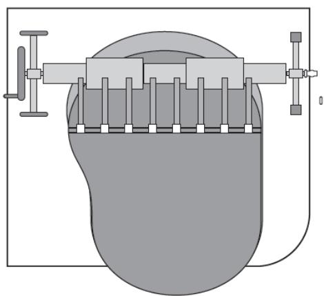
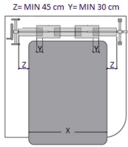
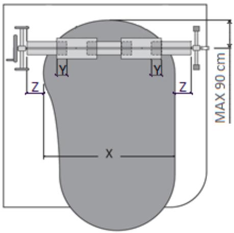
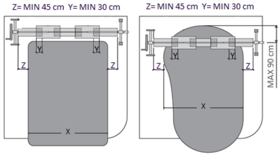
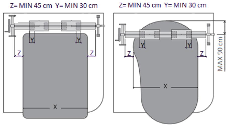
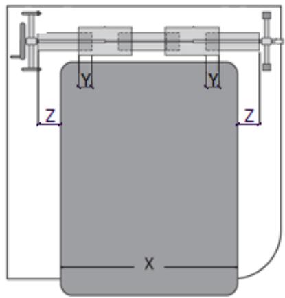
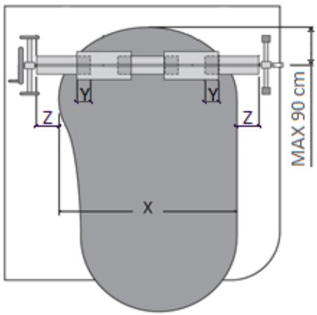
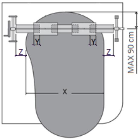
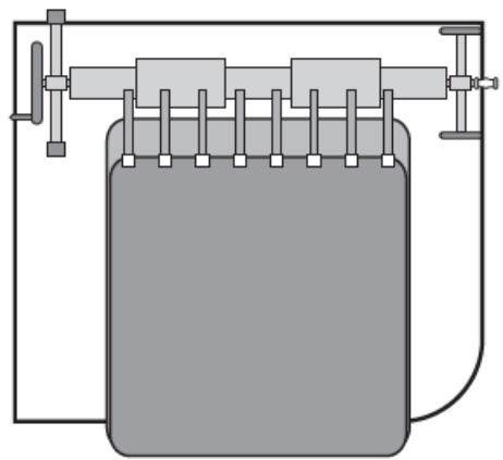
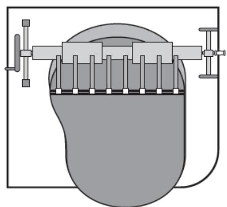
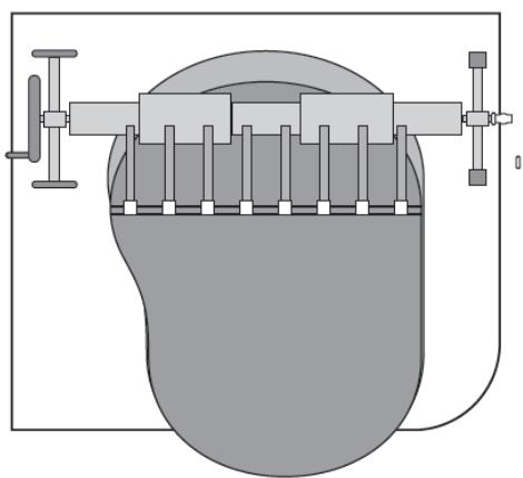
  1. (See fig. 9) Position both supports no closer than 45 cm from the opposite sides of the pool. In the case of a rectangular pool, the roller should be positioned along the shorter edge. In the case of an oval shaped pool, the roller should be positioned above the water surface no more than 90 cm from the edge.

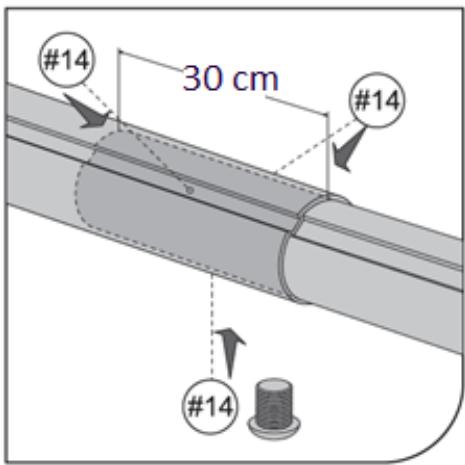
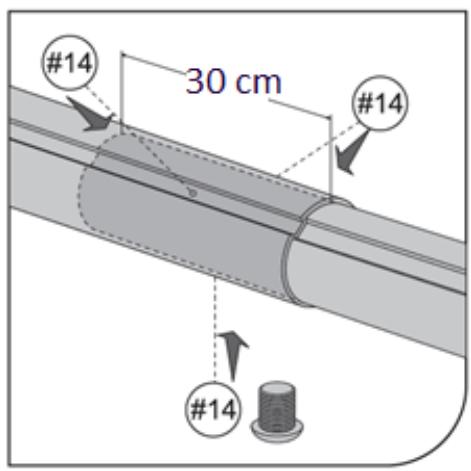
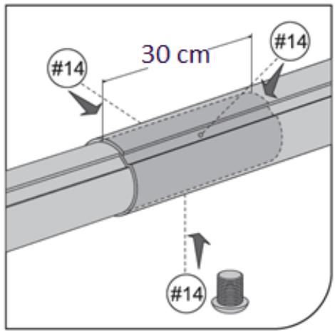
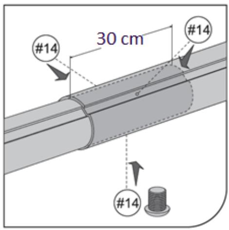
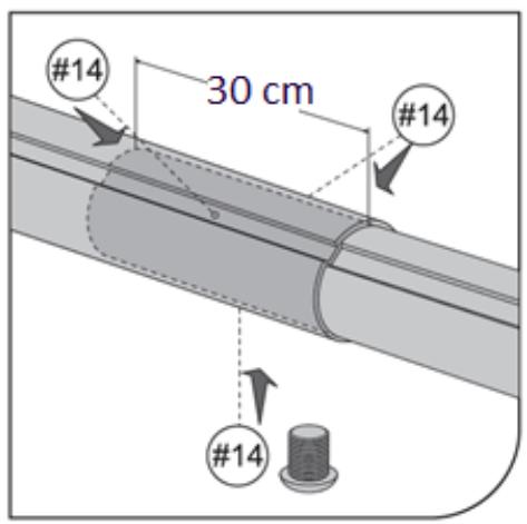
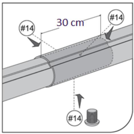
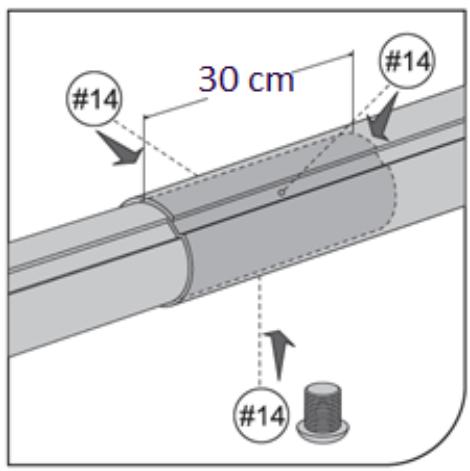
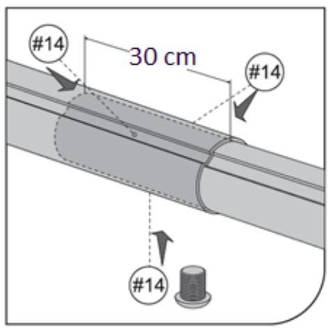
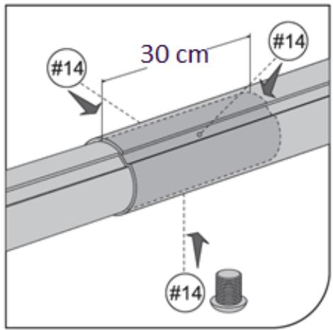
Connect the tubes of the roller so that their minimum overlap is not less than 30 cm.

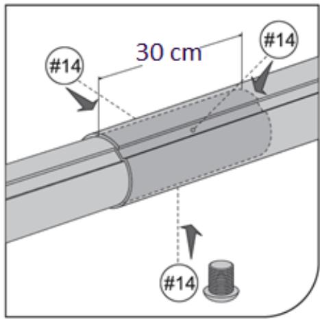
  1. (See fig. 10) Insert 3 screws (14) into the tube's connections, with the force ensuring stable position of the tubes in relation to each other.

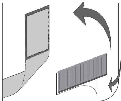
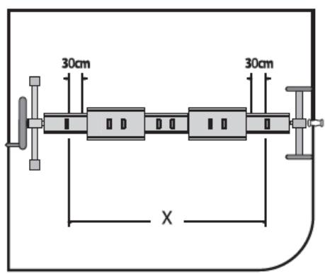
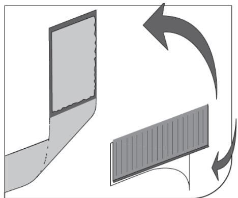
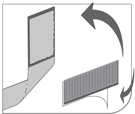
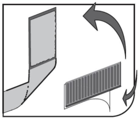
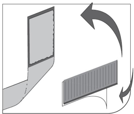
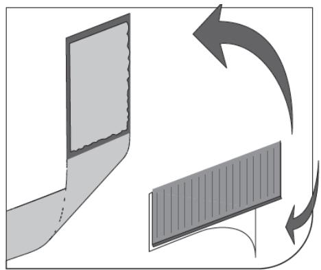
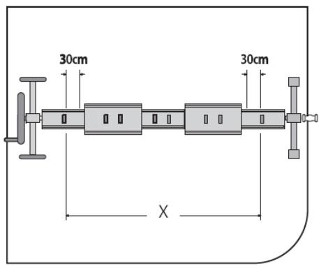
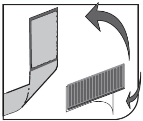
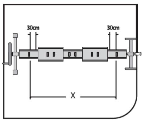
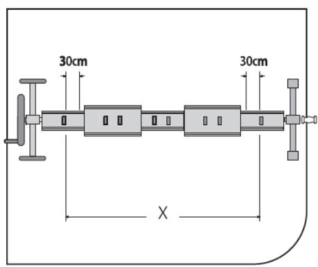
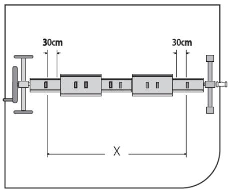
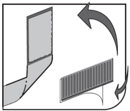
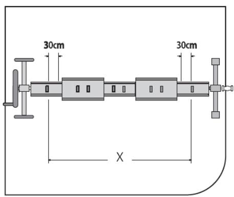
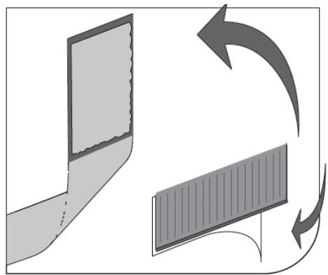
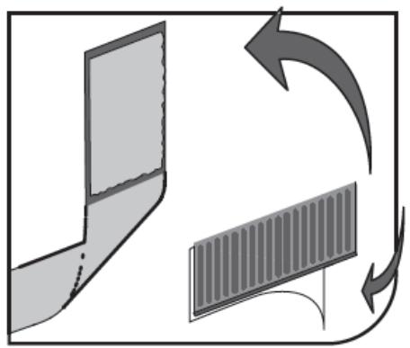
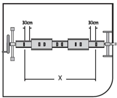
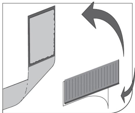
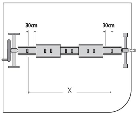
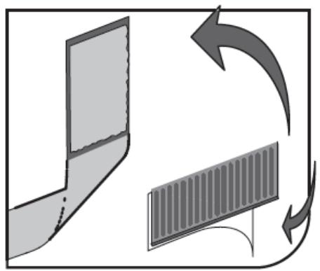
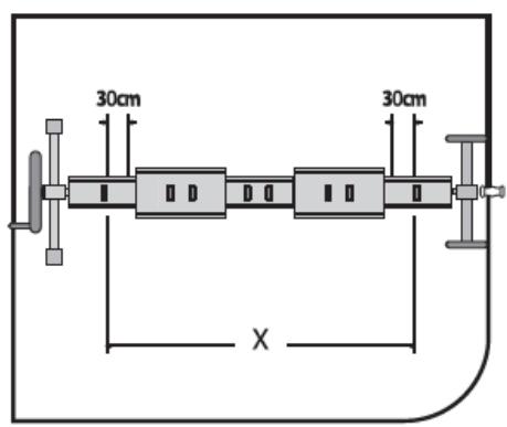
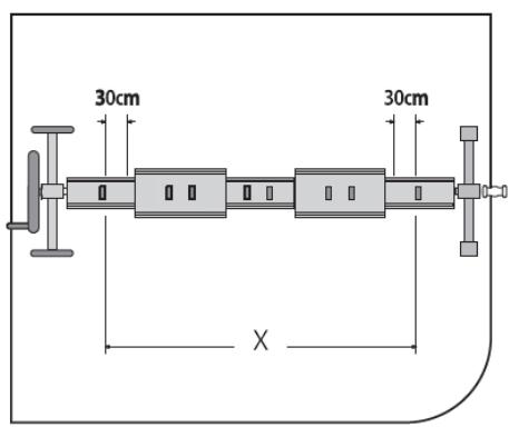
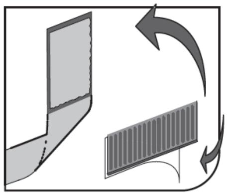
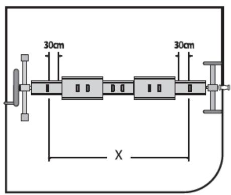
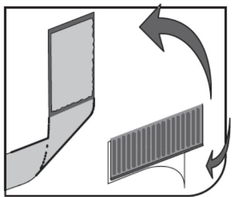
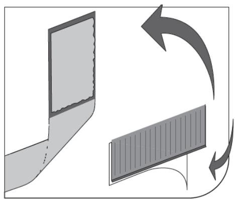
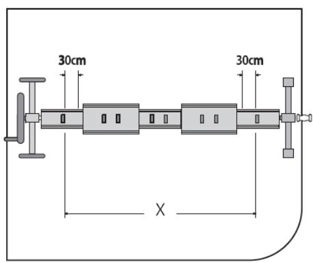
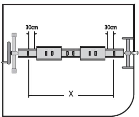
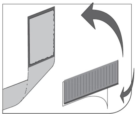
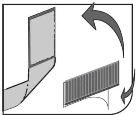
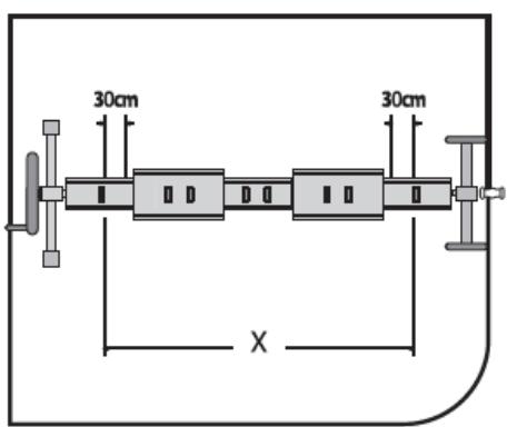
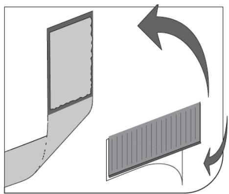
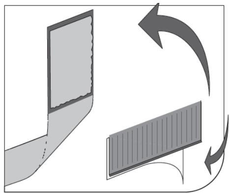
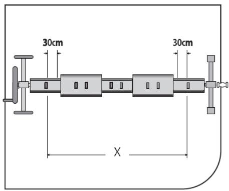
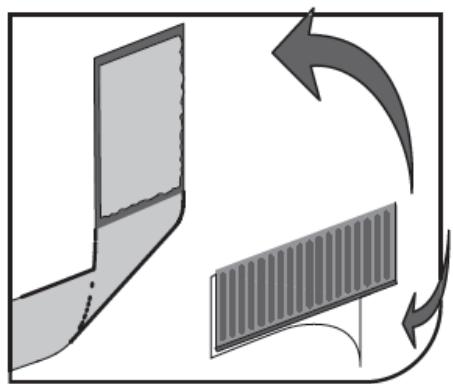
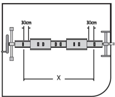
  2. (See fig. 11) Disconnect the male Velcro straps (23) from the female Velcro straps (22), remove the adhesive protection layer. Stick the male Velcro parts (23) on the roller, perpendicular to its axle at regular intervals, along the entire length of the pool. Velcro straps should be placed no closer than 30 cm to tubes connections.

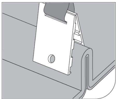
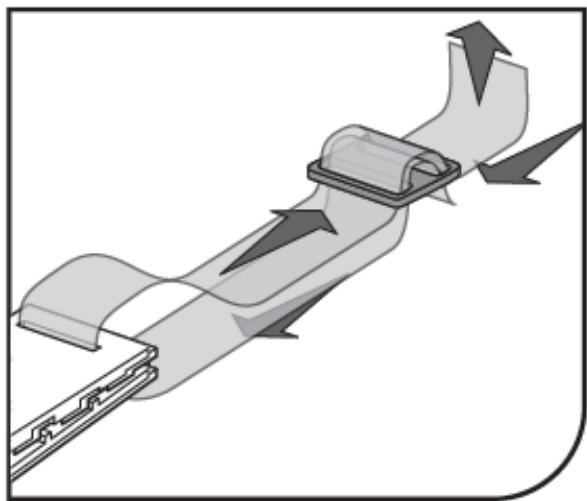
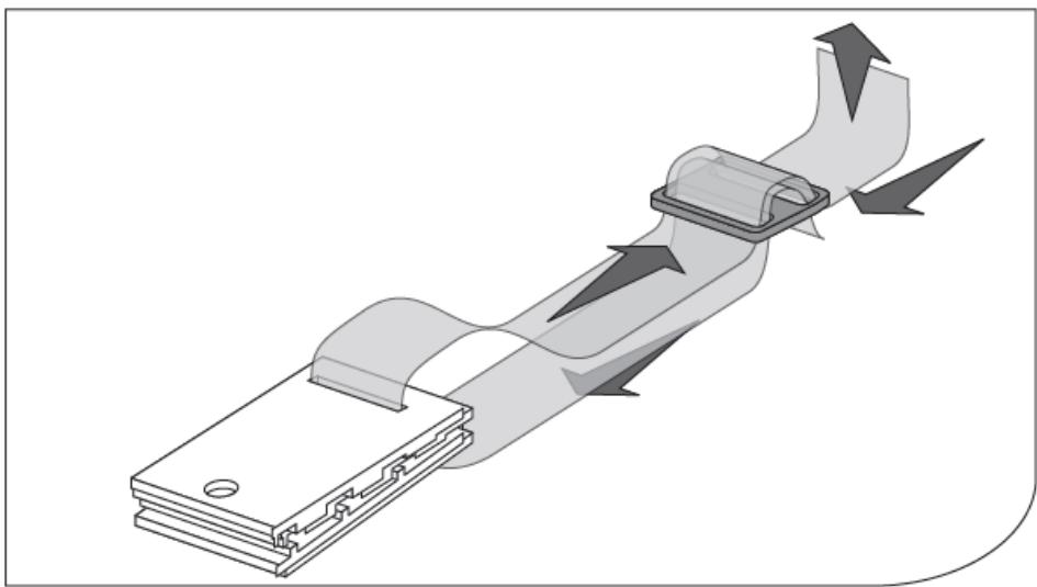
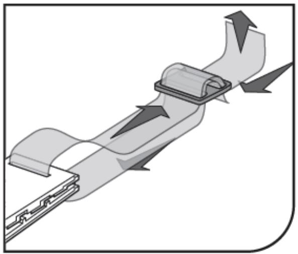
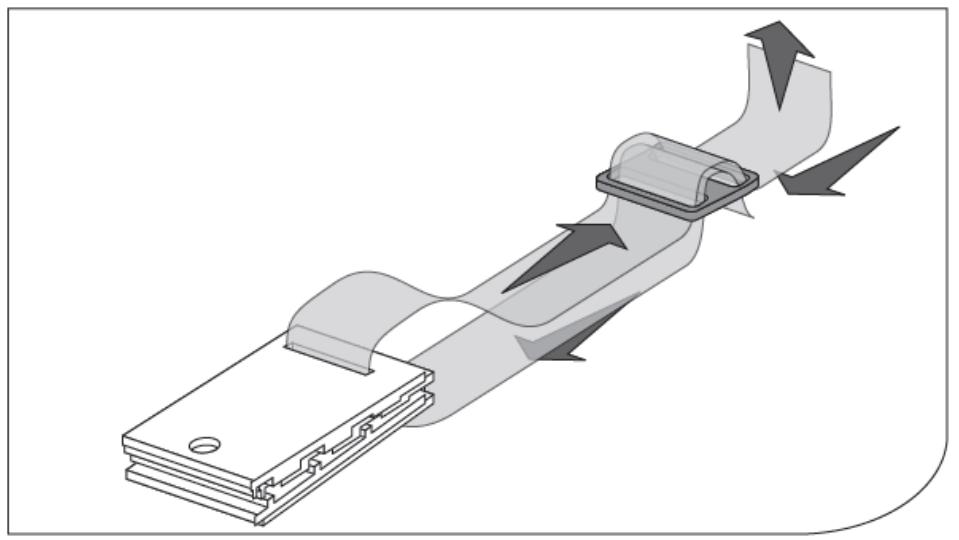
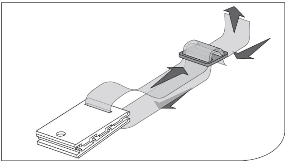
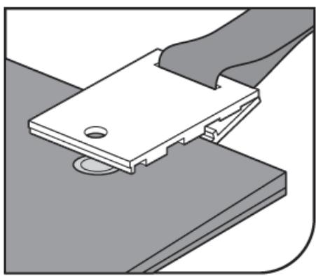
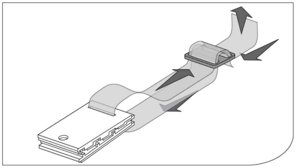
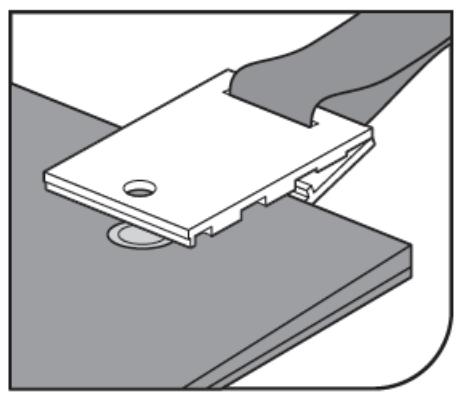
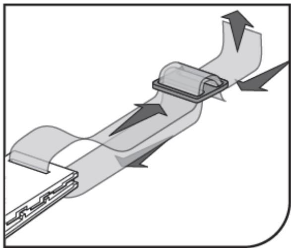
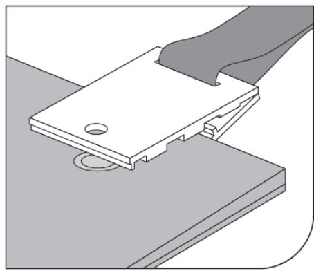
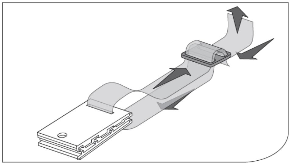
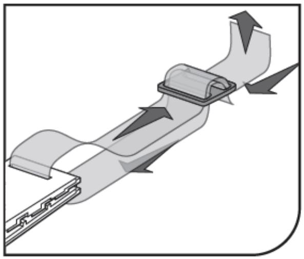
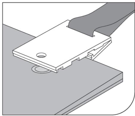
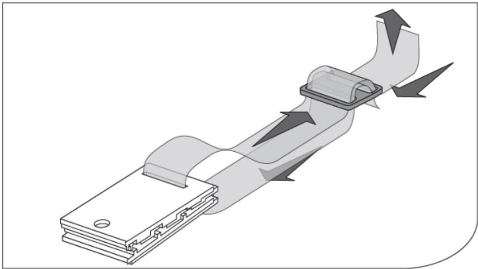
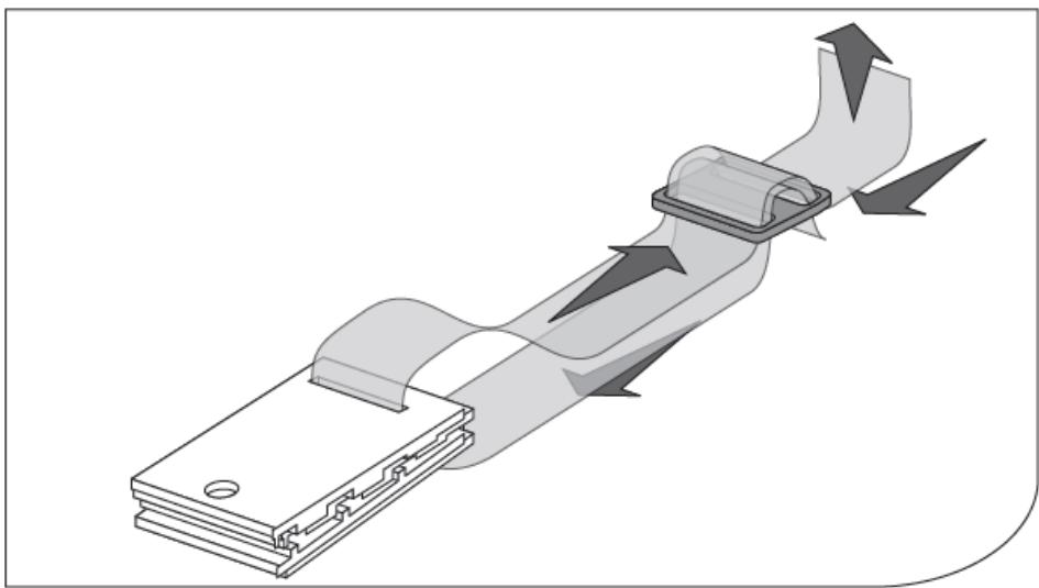
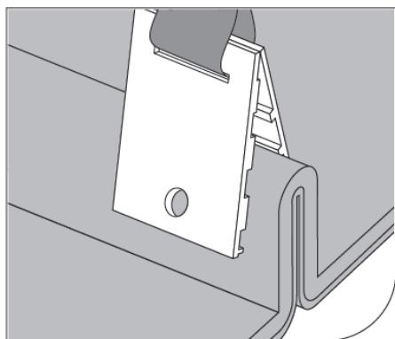
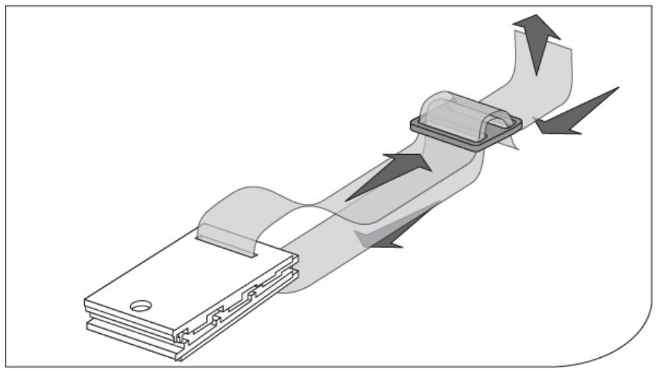
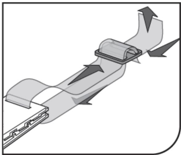
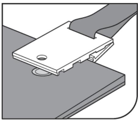
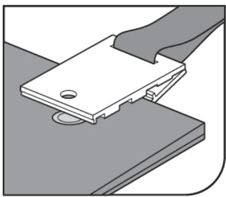
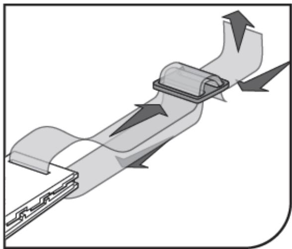
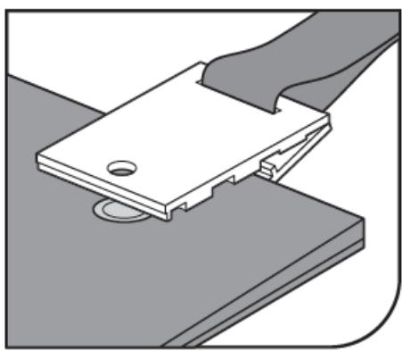
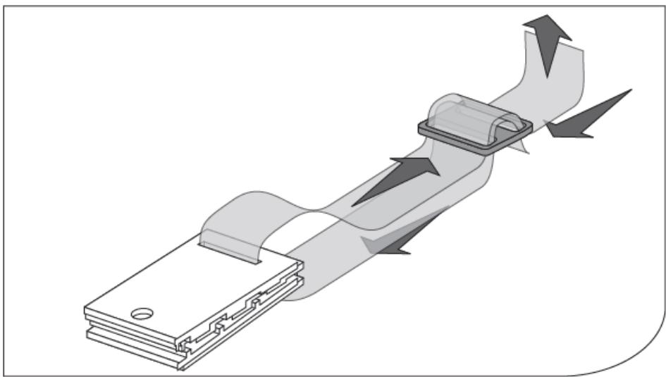
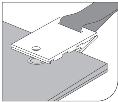
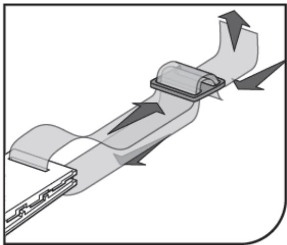
  3. (See fig. 12) Fit the clamp (25) and the clip (24) on the strap.

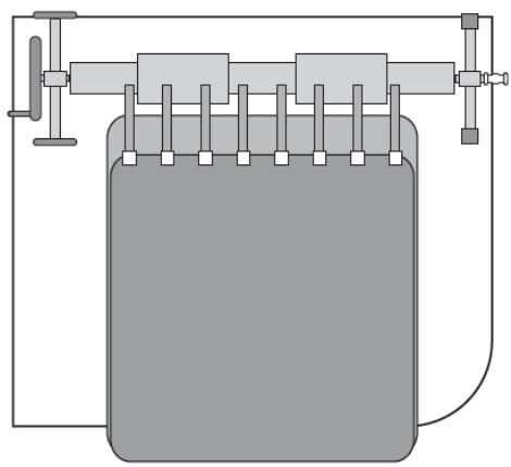
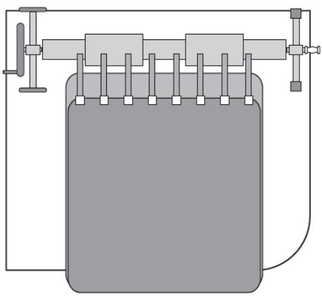
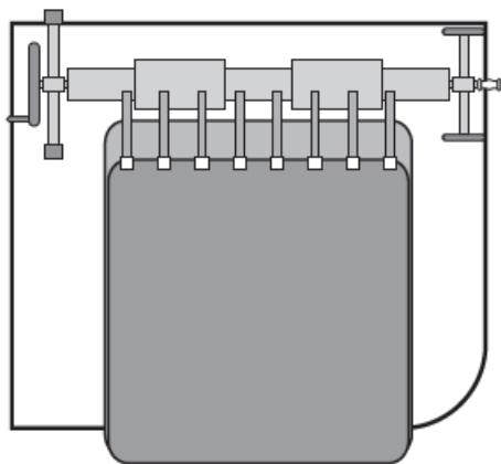
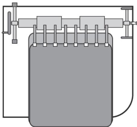
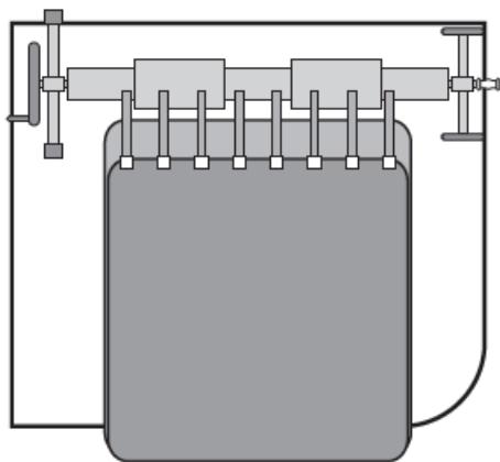
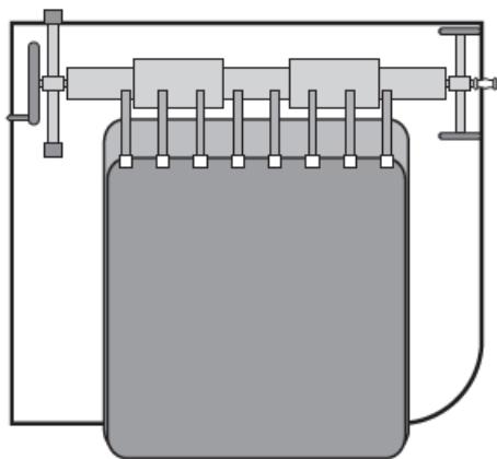
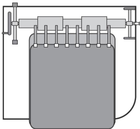
  4. (See fig. 13) In the case of rectangular pools:

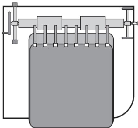
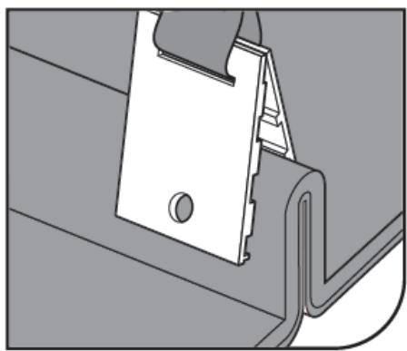
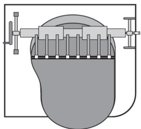
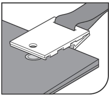
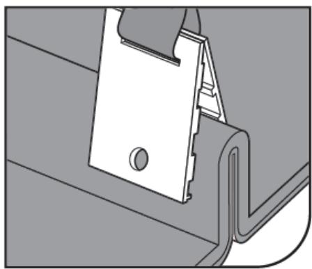
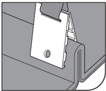
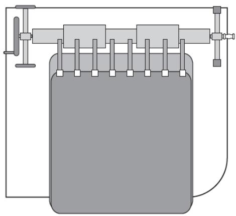
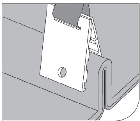
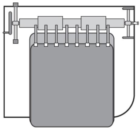
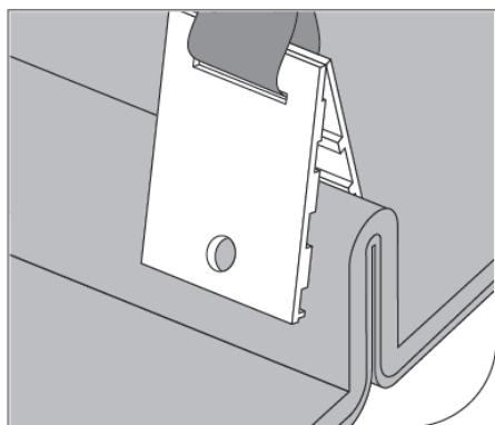
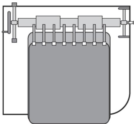
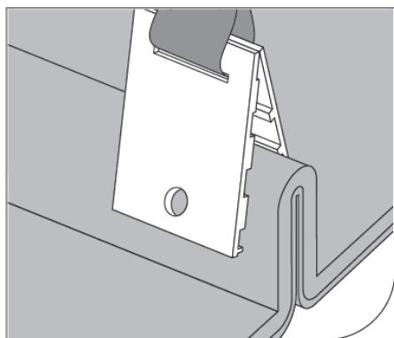
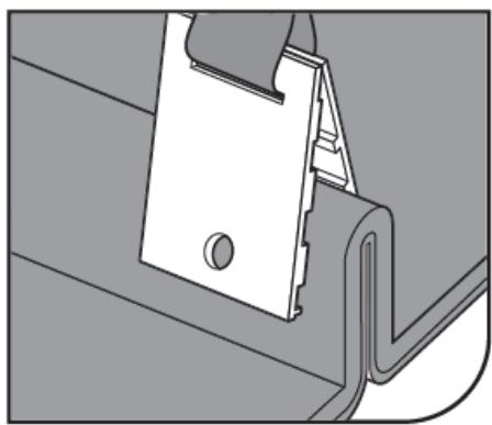
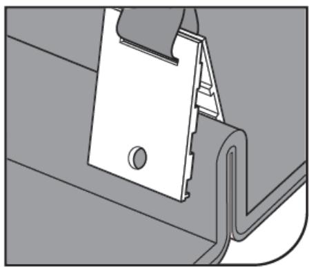
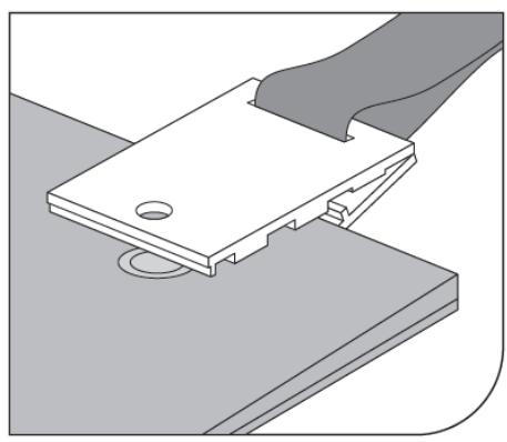
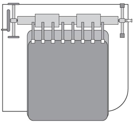
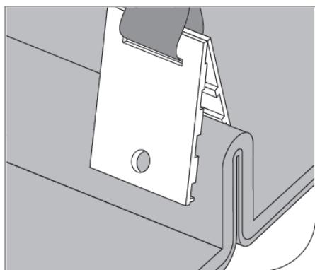
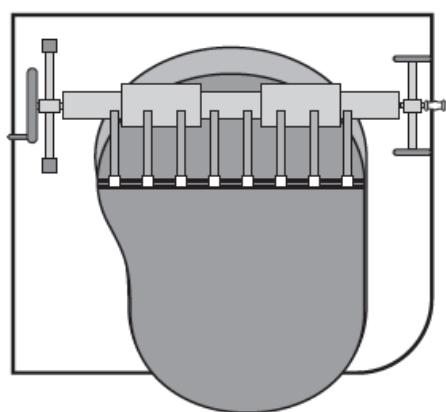
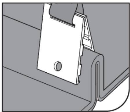
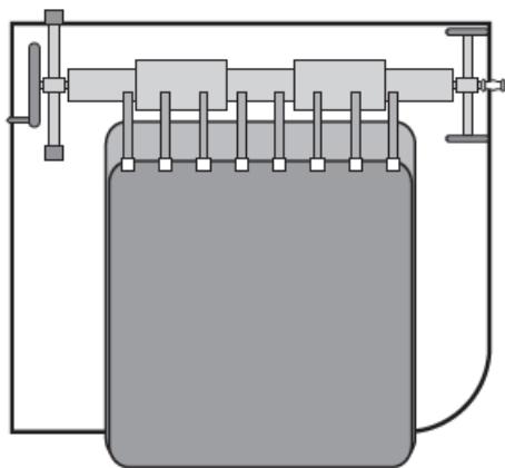
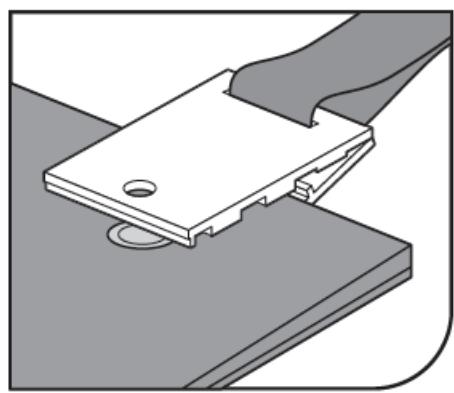
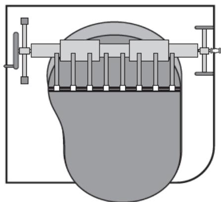
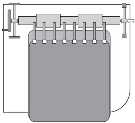
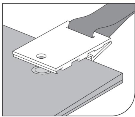
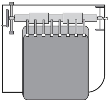
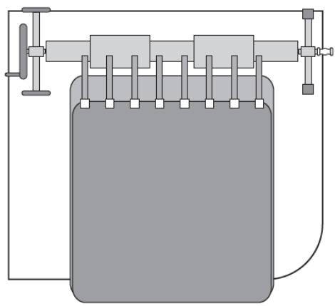
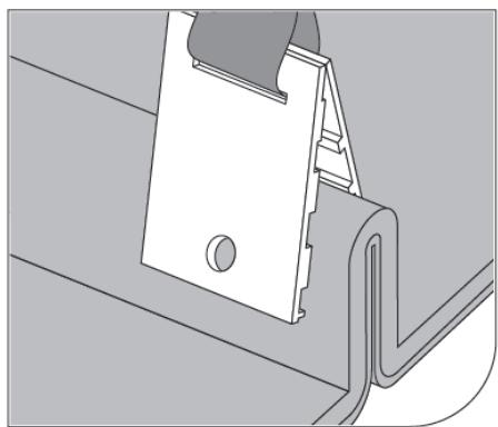
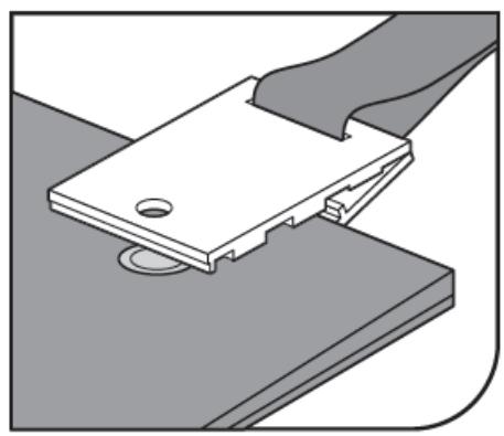
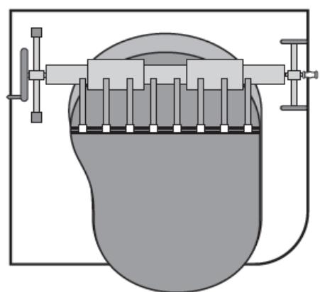
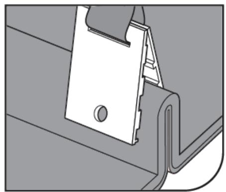
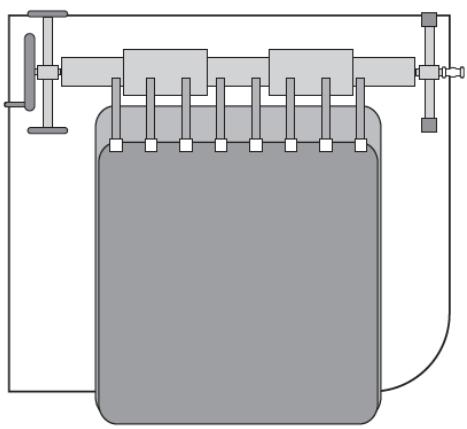
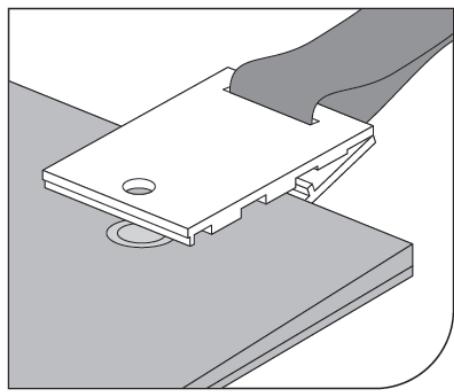
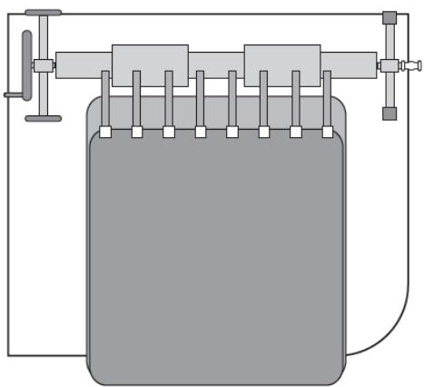
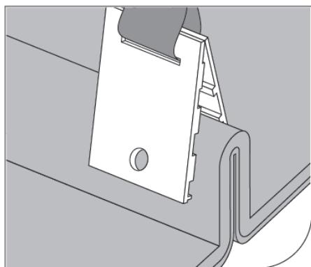
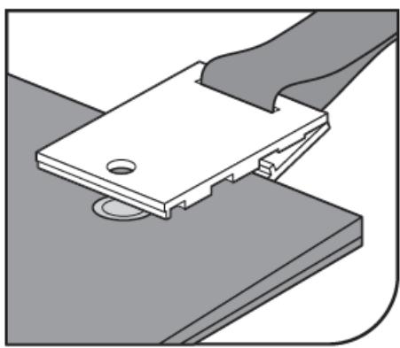
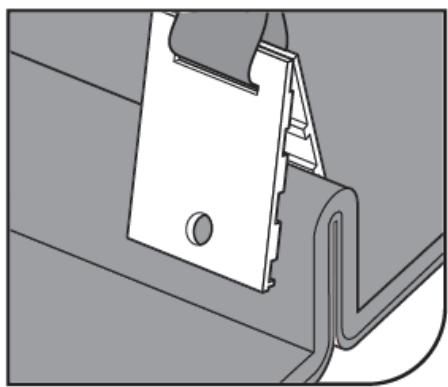
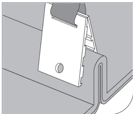
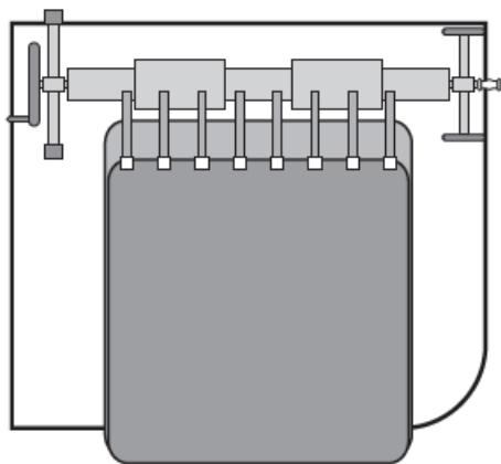
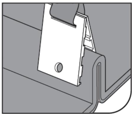
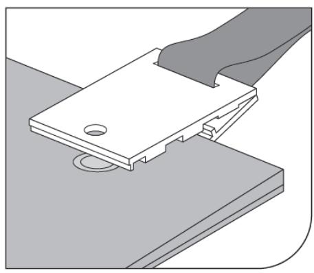
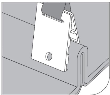
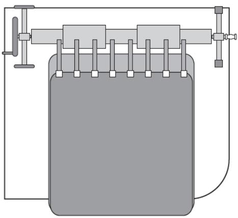
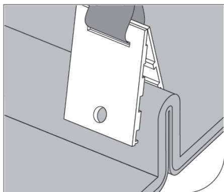
Spread the cover over the pool. Attach the clips (25) (as shown in the figure) for the cover, keeping at equal intervals a distance from the next clips (25) like the male Velcro parts (23) on the roller. Ensure that the length of the straps allows covering to lie flat on the pool surface to prevent air from blowing under the cover.

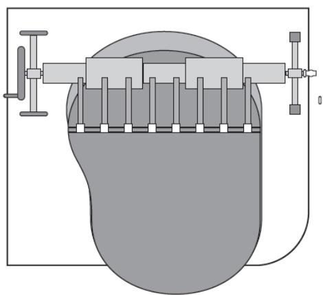
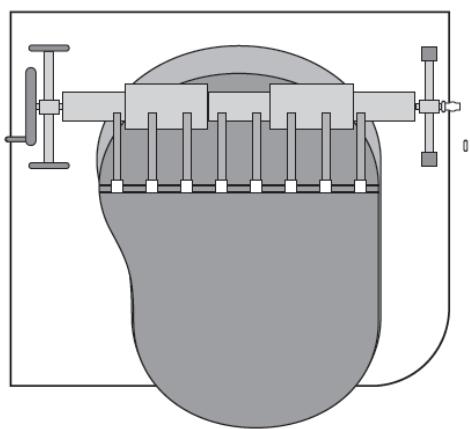
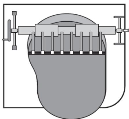
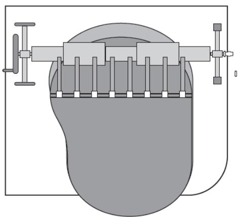
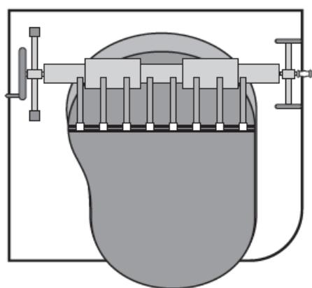
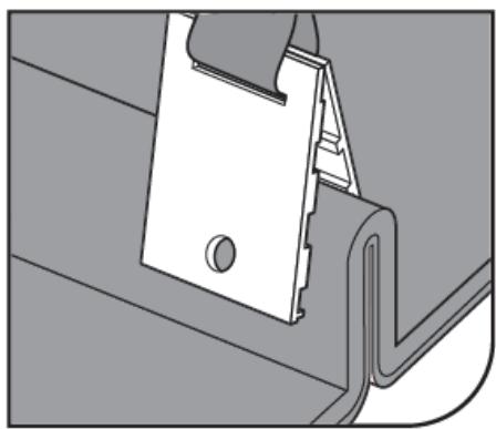
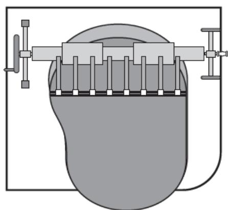
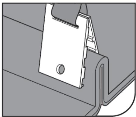
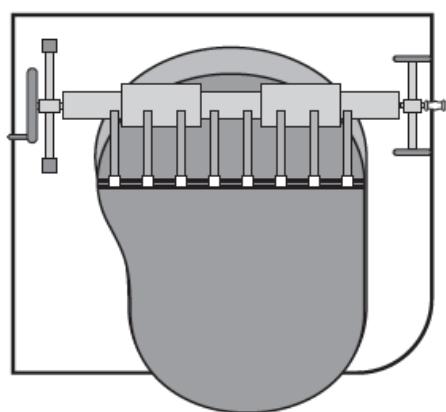
  1. (See fig. 14) For round or oval pools:

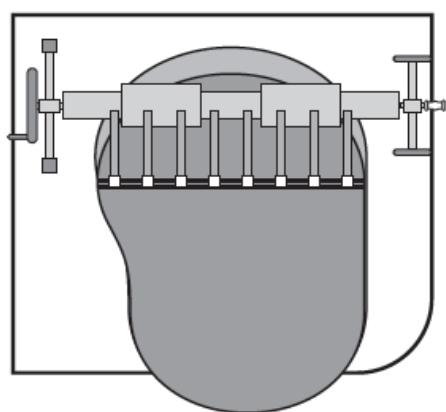
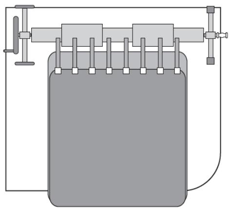
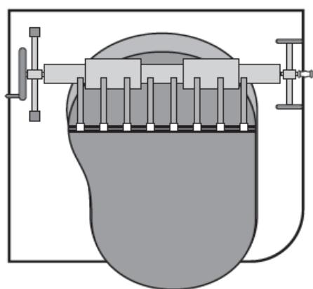
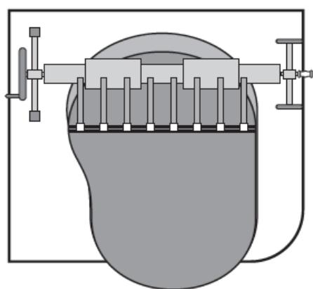
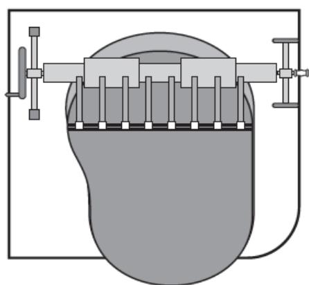
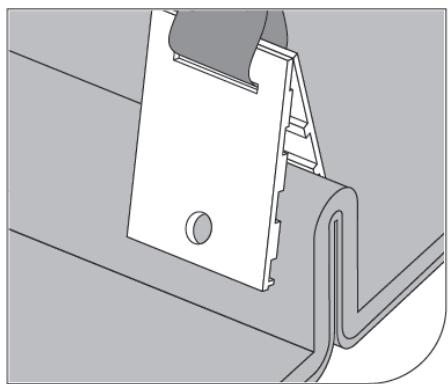
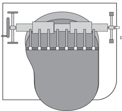
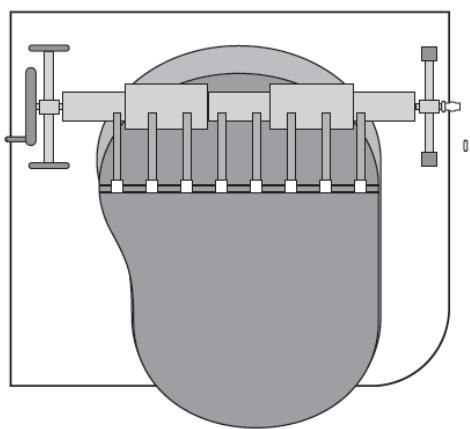
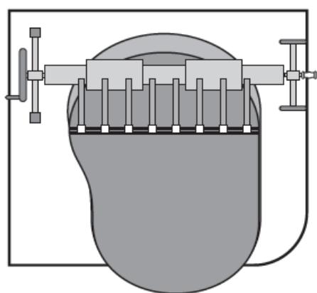
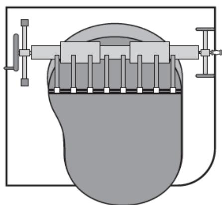
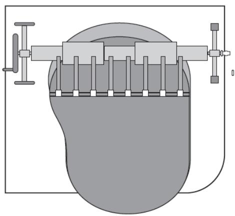
Spread the cover over the pool. Install the clips (25) (as shown in the figure) for covering at regular intervals at a distance like the male Velcro parts (23) on the roller. Ensure that the length of the straps allows covering to lie flat on the pool surface to prevent air from blowing under the cover.

3.2.2. UNI_POOL_REEL_570

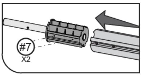
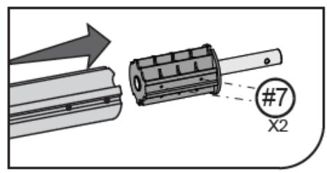
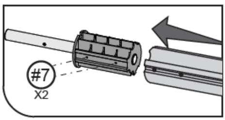
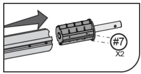
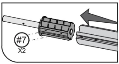
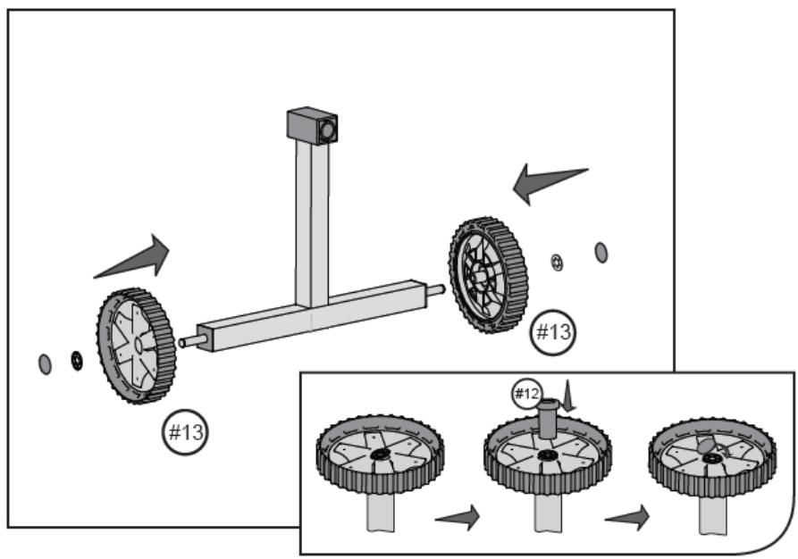
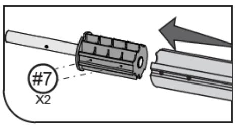
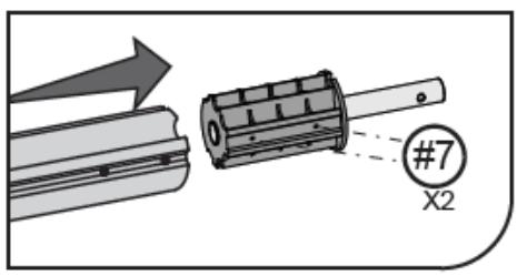
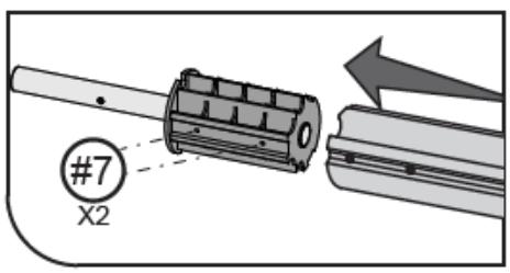
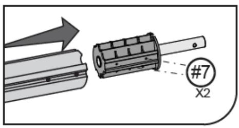
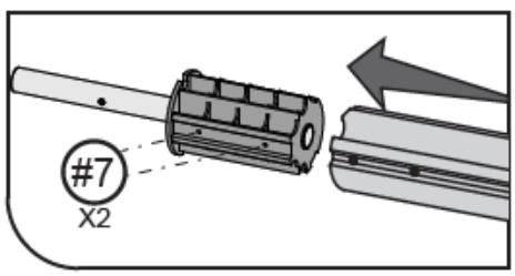
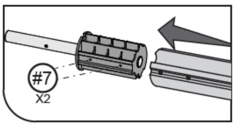
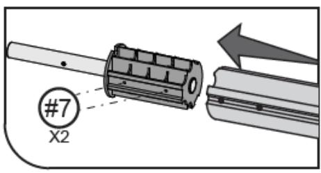
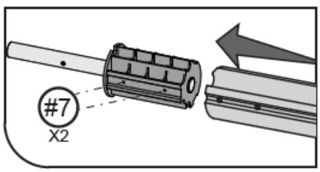
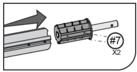
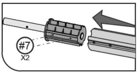
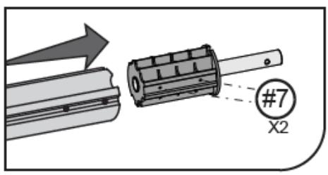
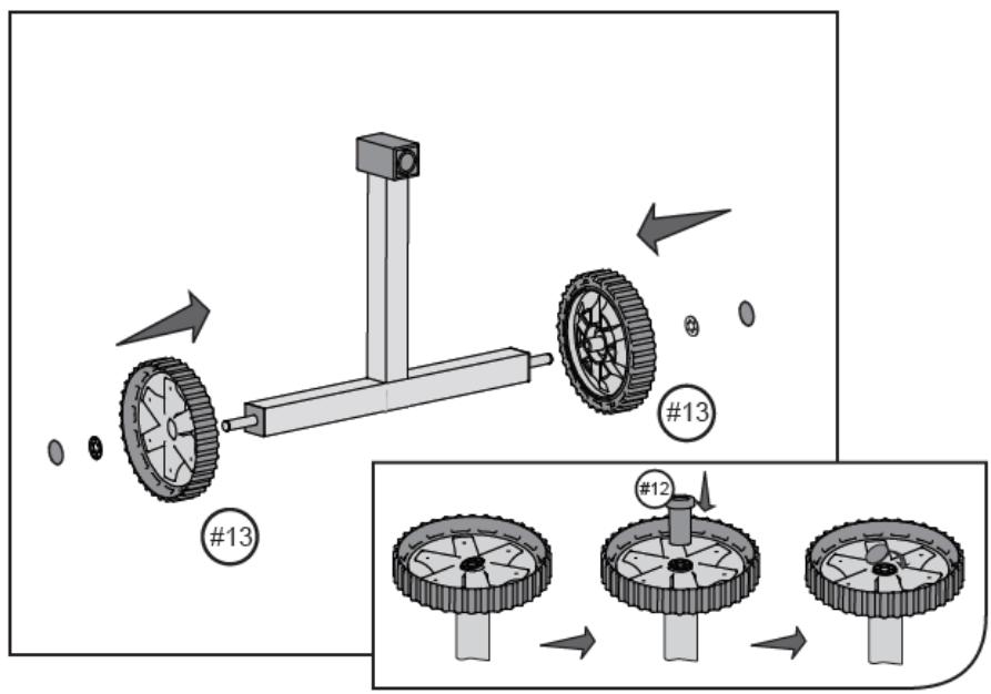
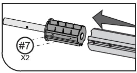
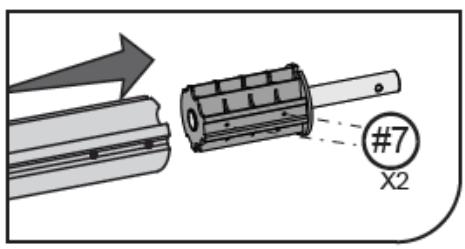
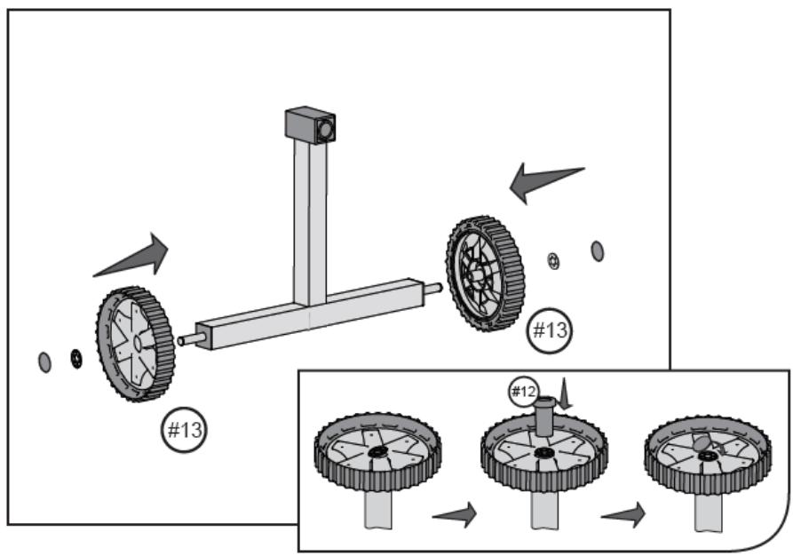
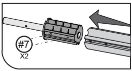
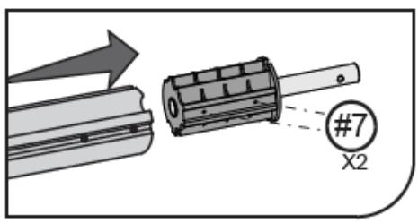
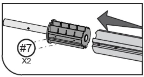
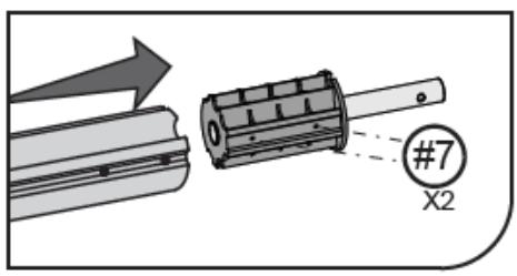
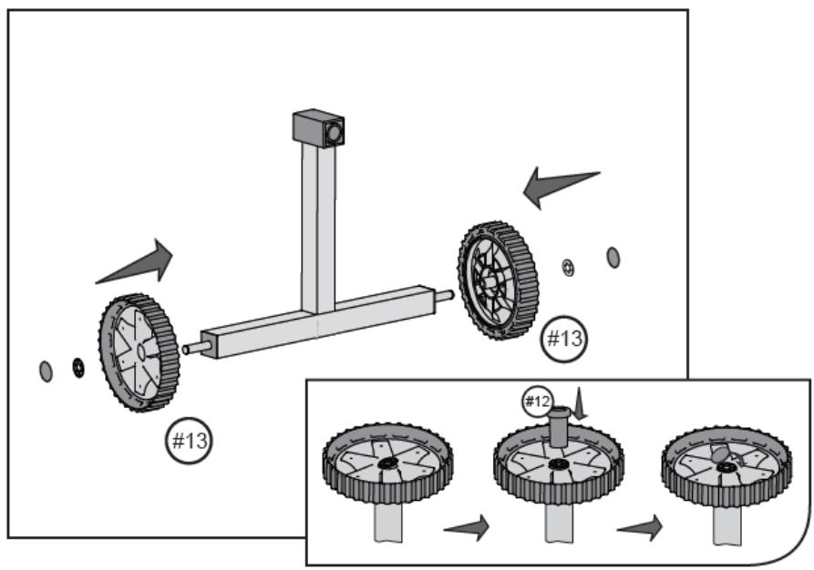
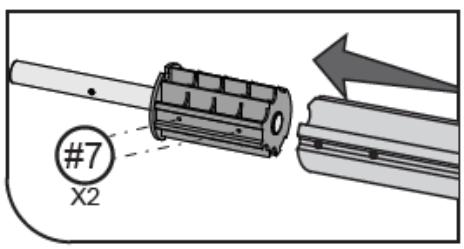
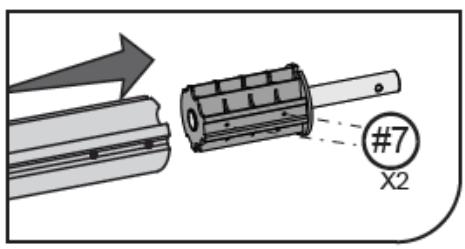
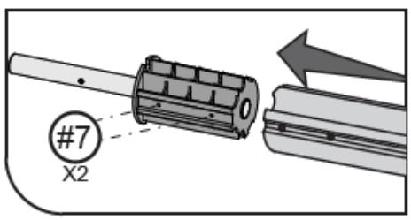
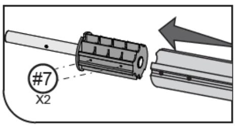
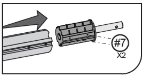
  1. (See fig. 15) Screw the axles of the roller with the screws (7) to the outer tubes type A.

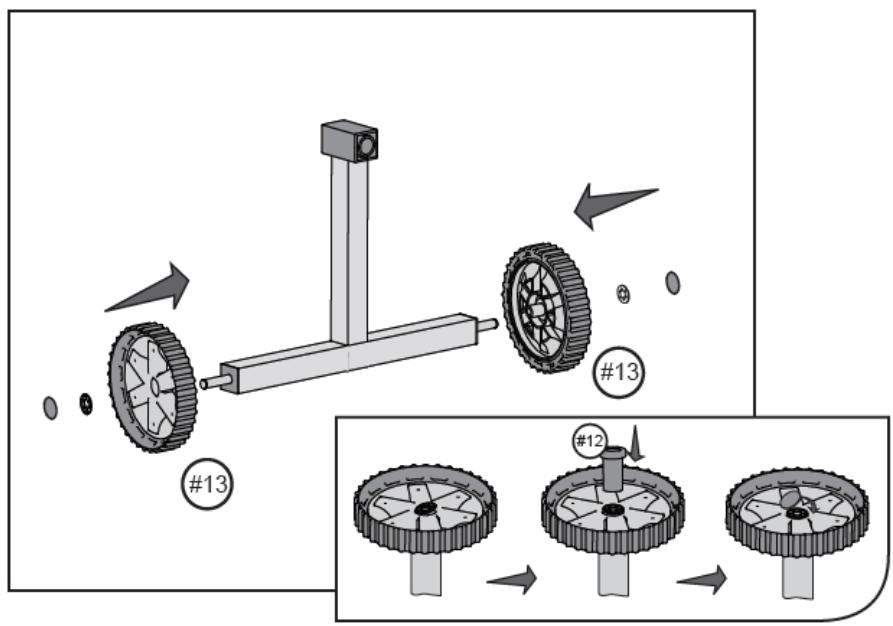
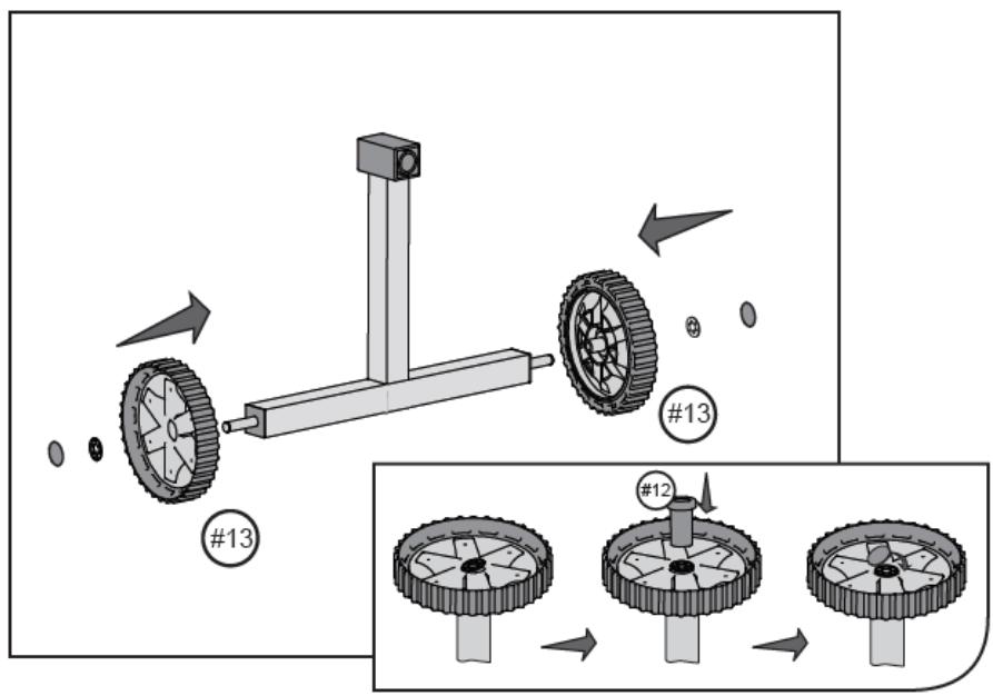
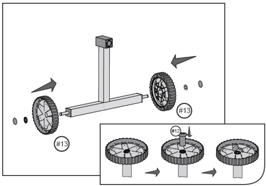
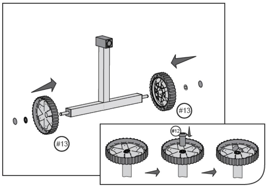
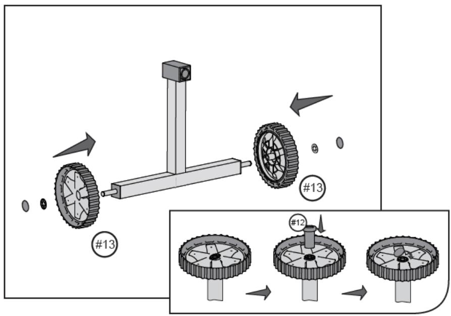
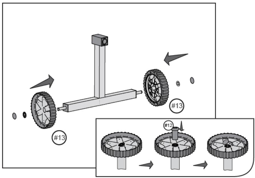
  2. (See fig. 16) Place the wheels (13) on the axles of the base beam (2), insert the roll (12) into the centre of the wheels and secure the connection with a washer and a plug.

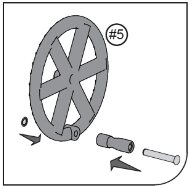
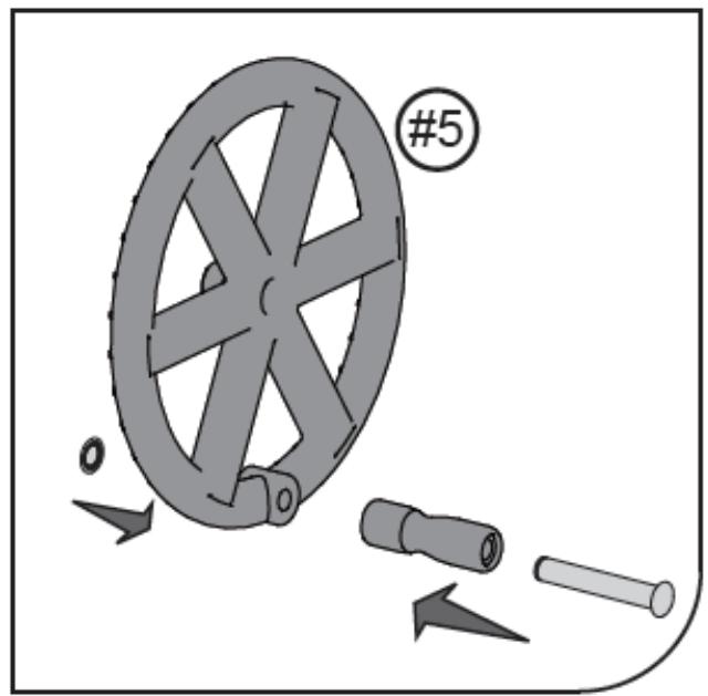
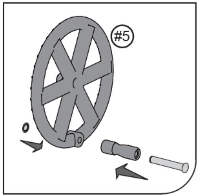
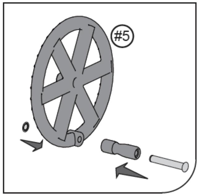
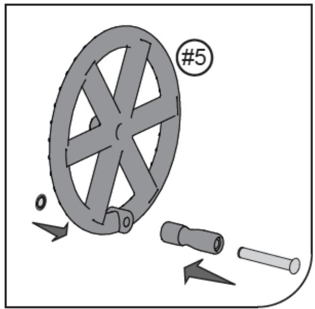
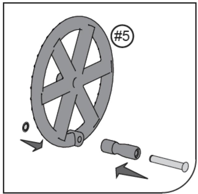
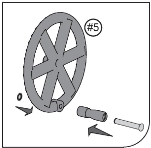
  3. (See fig. 17) Insert the roll into the rod and then fasten both parts in the wheel to drive the roller (5). Secure the connection with the plug.

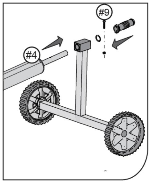
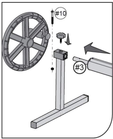
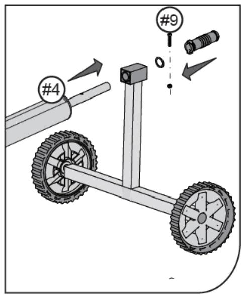
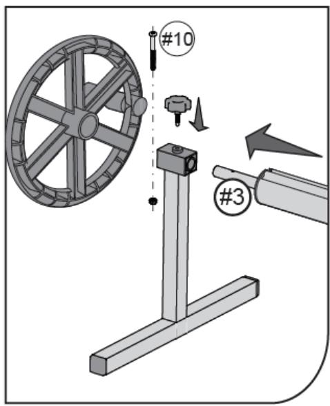
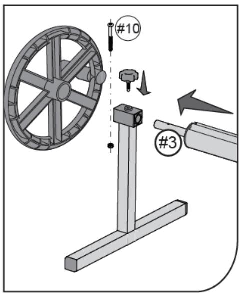
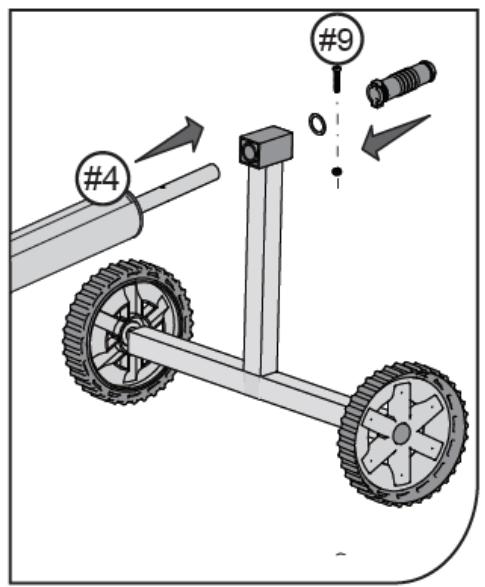
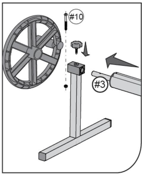
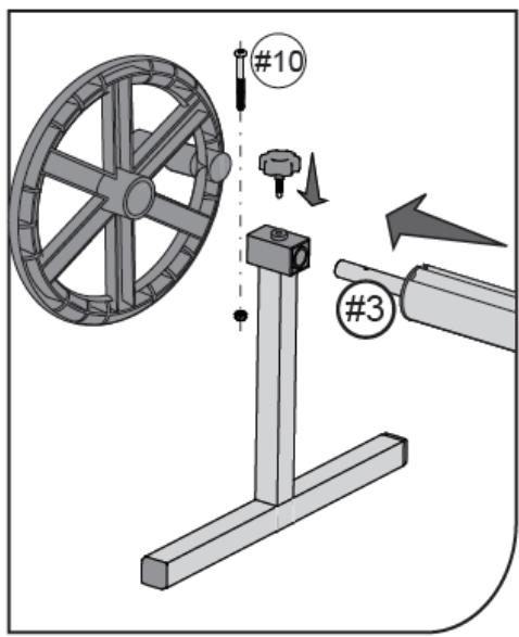
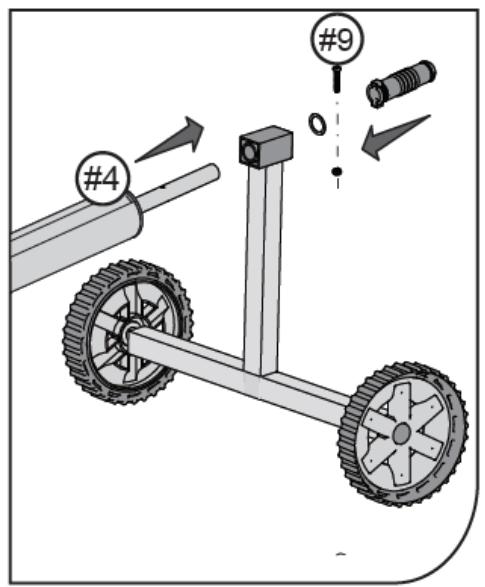
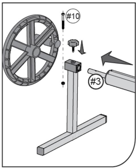
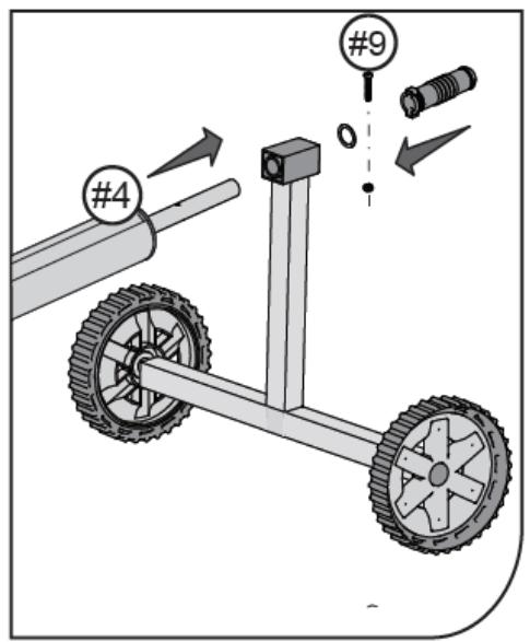
  4. (See fig. 18) Put the roller axle (3) through the fixed support (2) and install the wheel on it to drive the roller (5). Secure the connection with the screw and nut (10). In the upper part of the fixed support (2), install the clamp screw.

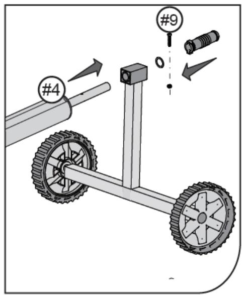
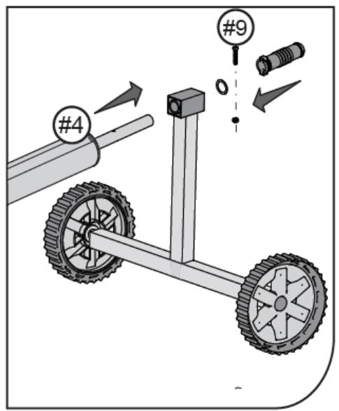
Put the roller axle (4) through the hole in the movable support (1) and mount the washer (11) and the holder (6) on it. Secure the connection with the screw and nut (9).

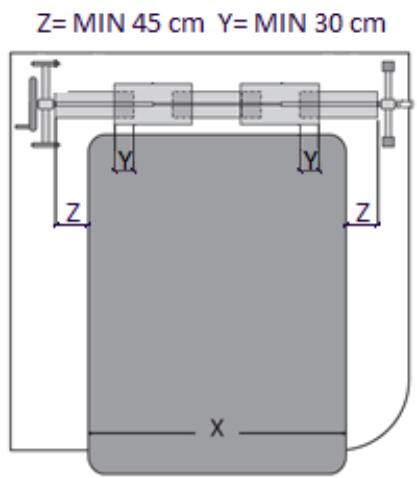
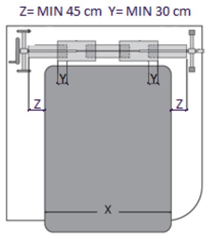
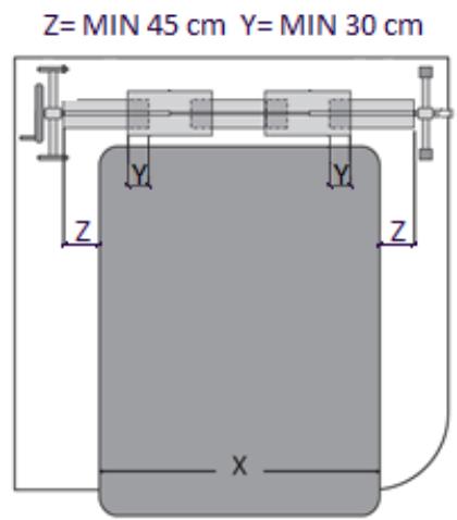
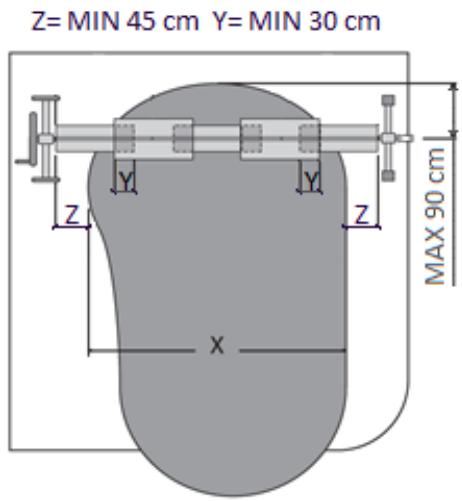
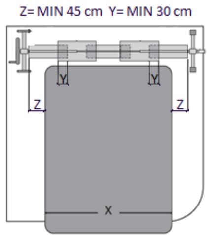
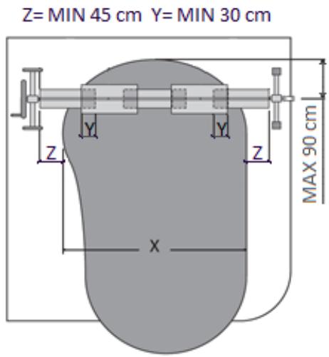
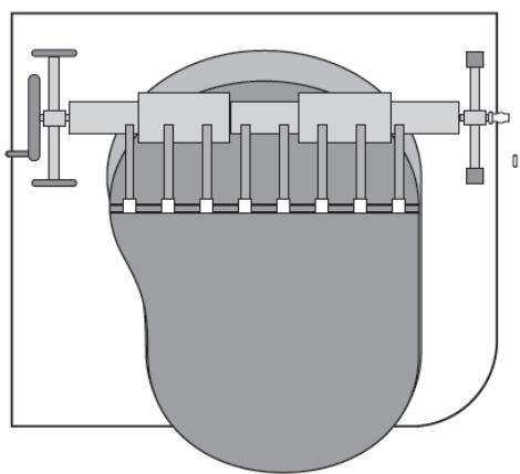
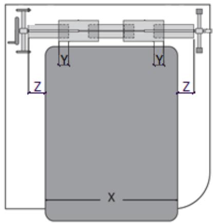
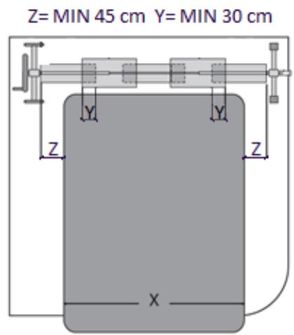
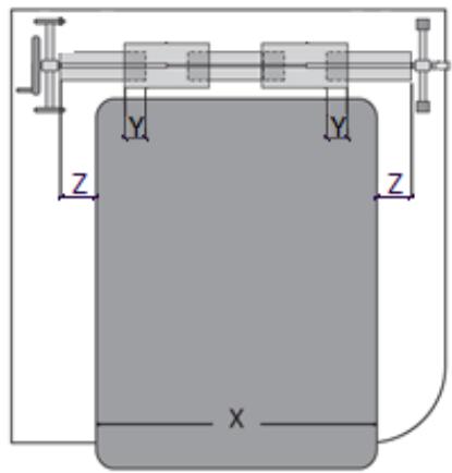
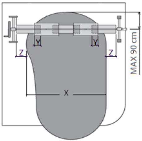
  1. (See fig. 19) Position both supports no closer than 45 cm from the opposite sides of the pool. In the case of a rectangular pool, the roller should be positioned along the shorter edge. In the case of an oval shaped pool, the roller should be positioned above the water surface no more than 90 cm from the edge.
    Connect the tubes of the roller so that their minimum overlap is not less than 30 cm.

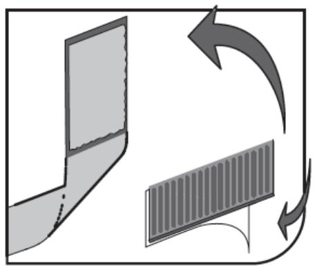
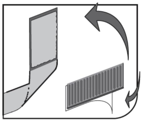
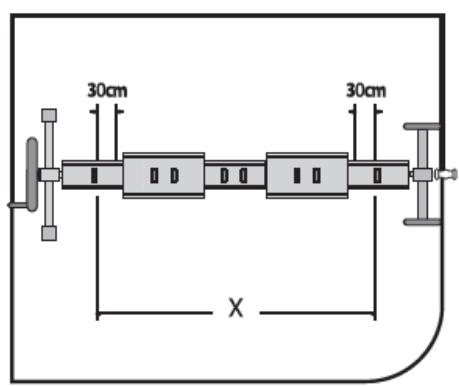
  2. (See fig. 20) Disconnect the male Velcro straps (15) from the female Velcro straps (14), remove the adhesive protection layer. Stick the male Velcro parts (15) on the roller, perpendicular to its axle at regular intervals, along the entire length of the pool. Velcro straps should be placed no closer than 30 cm to tubes connections.

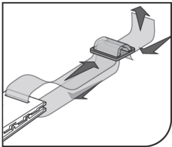
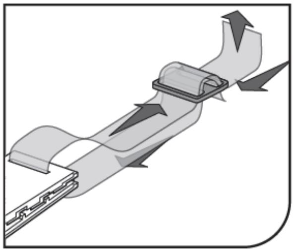
  3. (See fig. 21) Fit the clamp (16) and the clip (17) on the strap.

  4. (See fig. 22) In the case of rectangular pools:

Spread the cover over the pool. Mount the clips (17) (as shown in the figure) for covering at regular intervals at a distance as the male Velcro parts (15) on the roller. Ensure that the length of the straps allows covering to lie flat on the pool surface to avoid blowing air under the cover.

  1. (See fig. 23) For round or oval pools:

Spread the cover over the pool. Mount the clips (17) (as shown in the figure) for covering at regular intervals at a distance as the male Velcro parts (15) on the roller. Ensure that the length of the straps allows covering to lie flat on the pool surface to avoid blowing air under the cover.

3.2.3. UNI_POOL_REEL_585

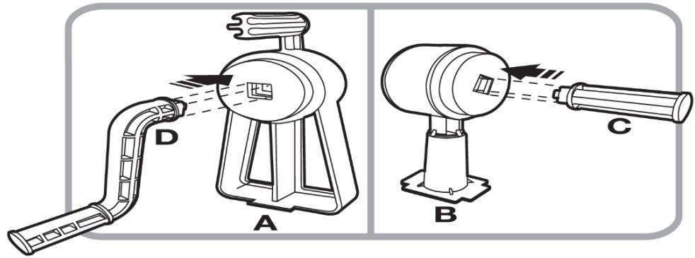
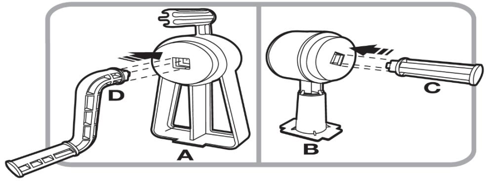
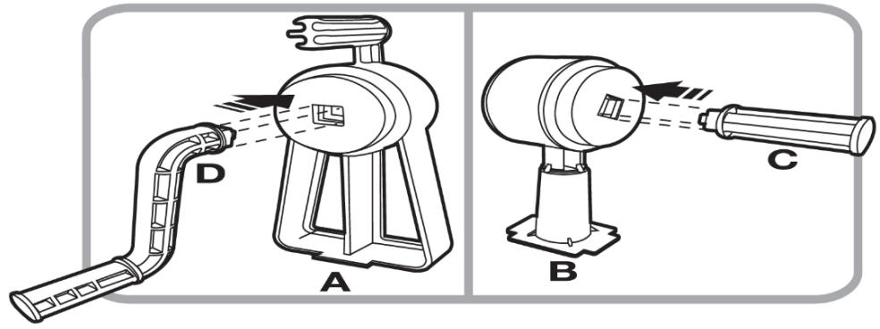
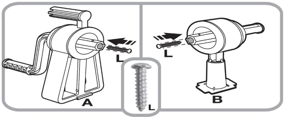
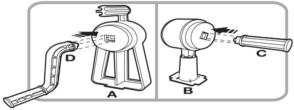
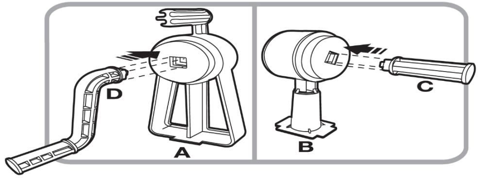
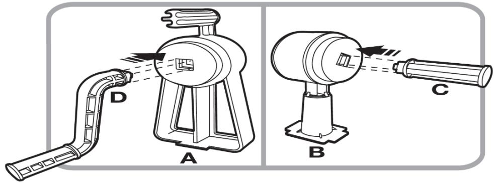
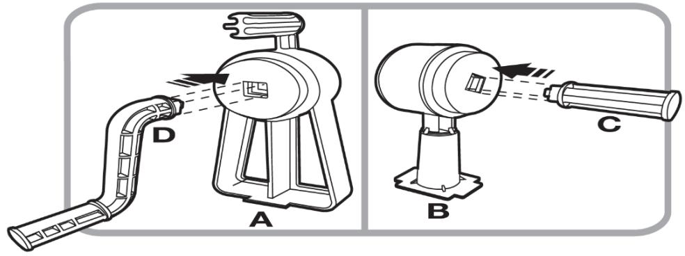
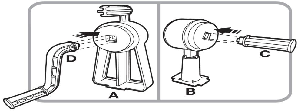
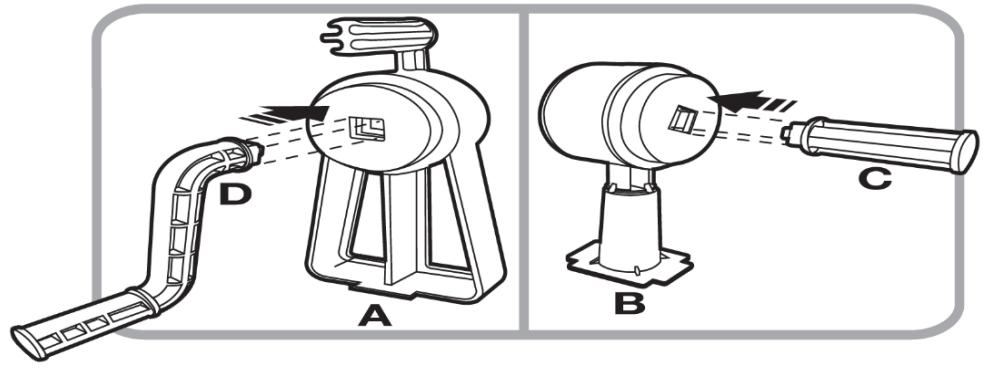
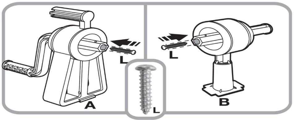
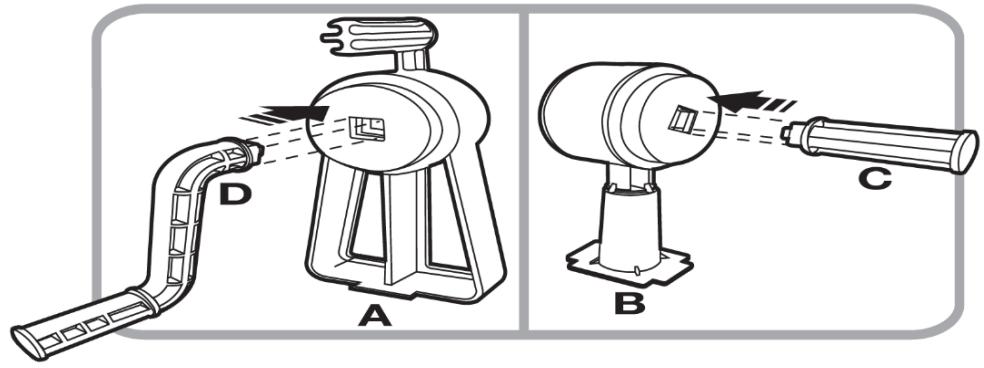
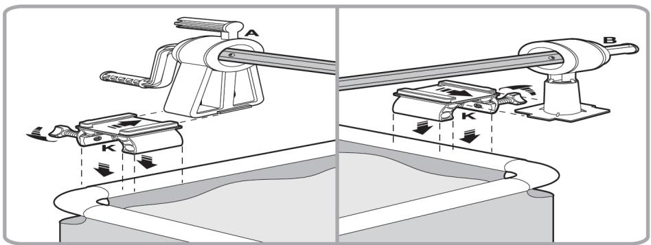
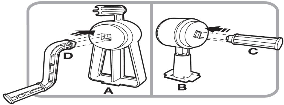
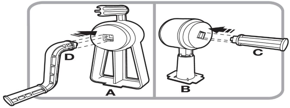
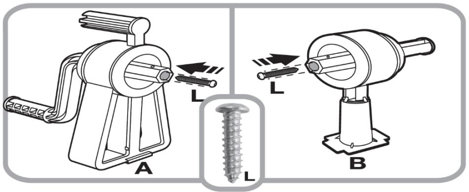
  1. (See fig. 24) Insert the levers (D) into the support (A), then slide the holder (C) into the support (B).
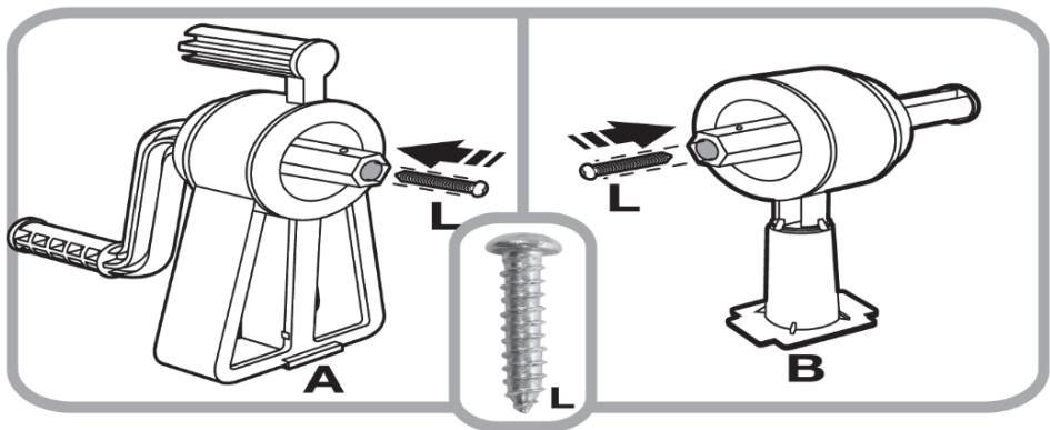
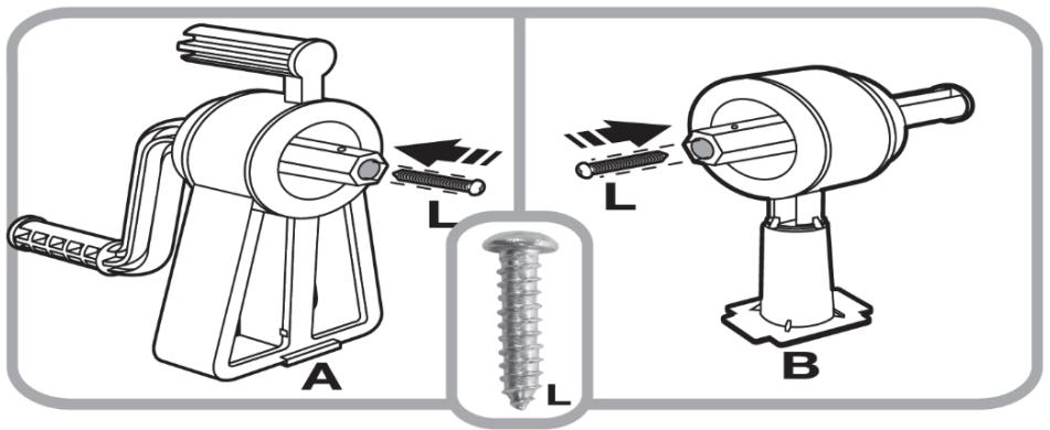
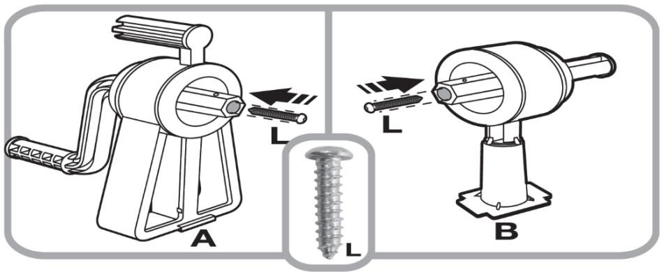
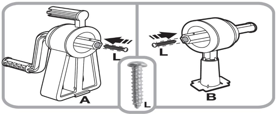
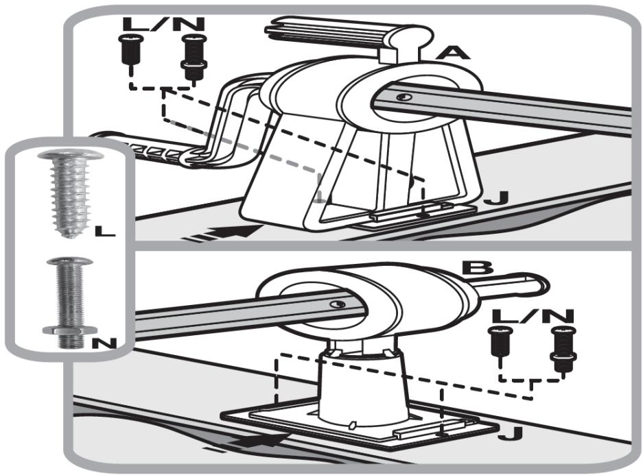
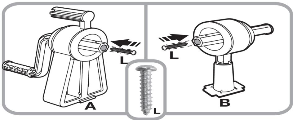
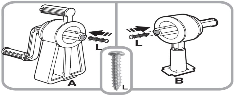
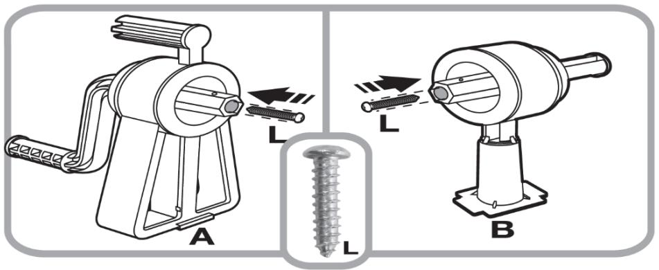
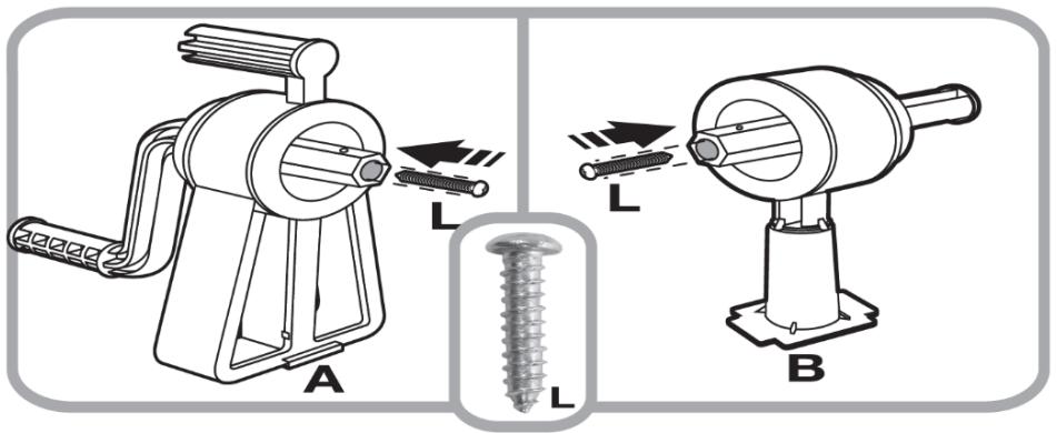
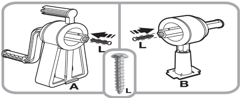
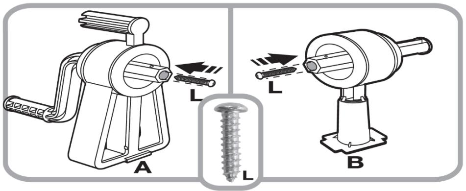
  2. (See fig. 25) Screw the bolt (L) into the hole in the base (A) and (B). It is recommended to use a screwdriver with a magnetic tip that will hold the screw during assembly.
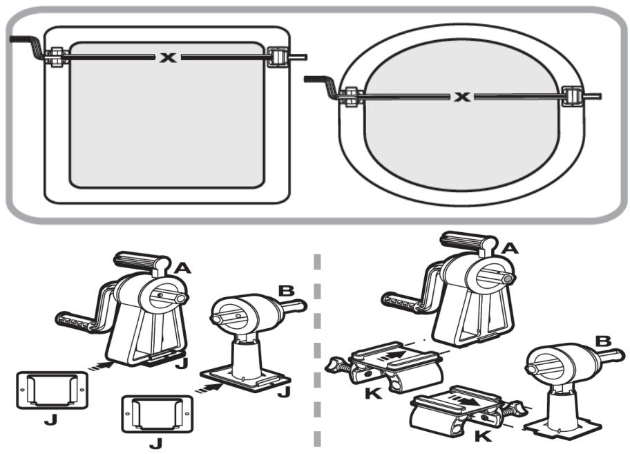
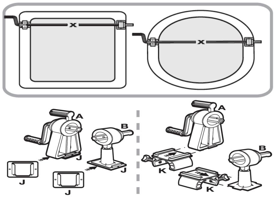
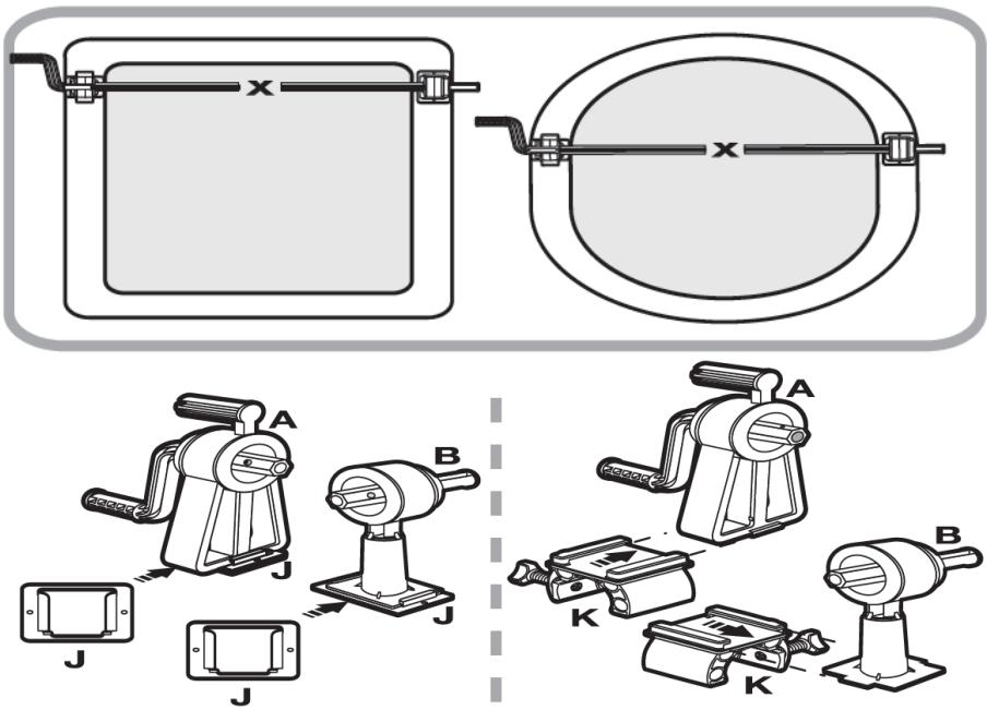
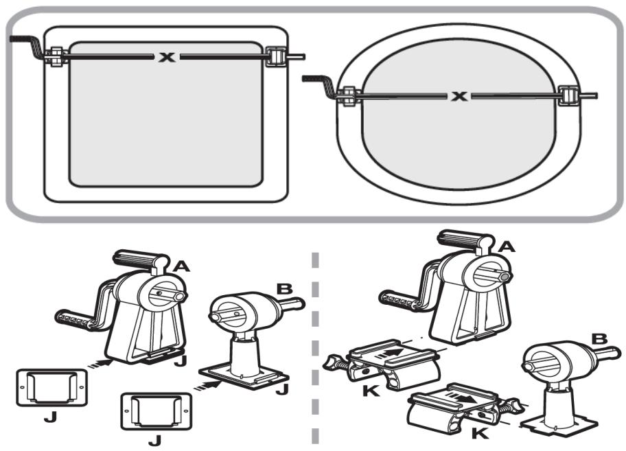
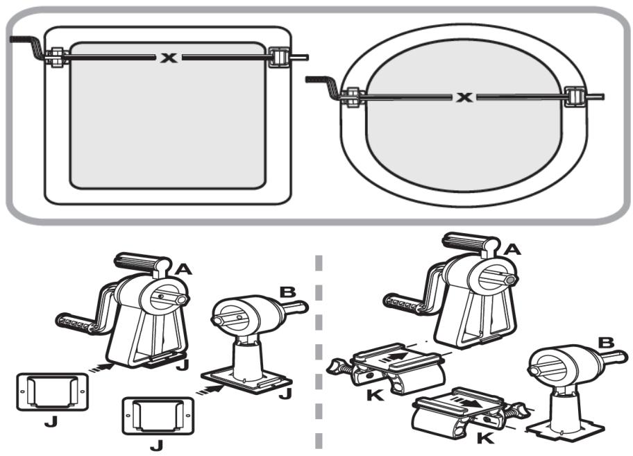
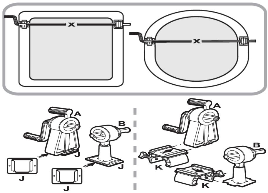
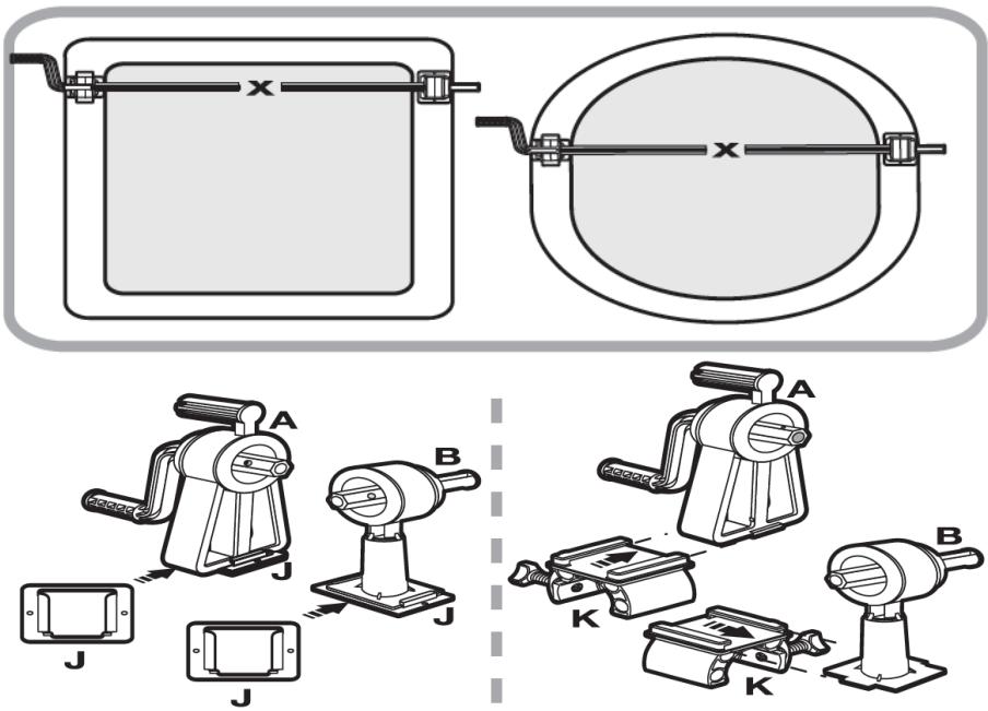
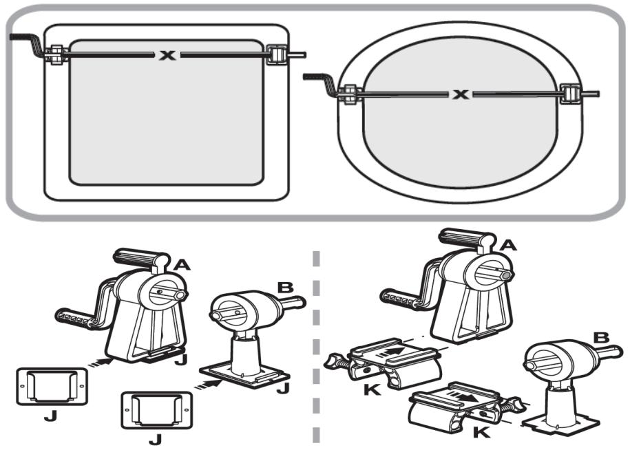
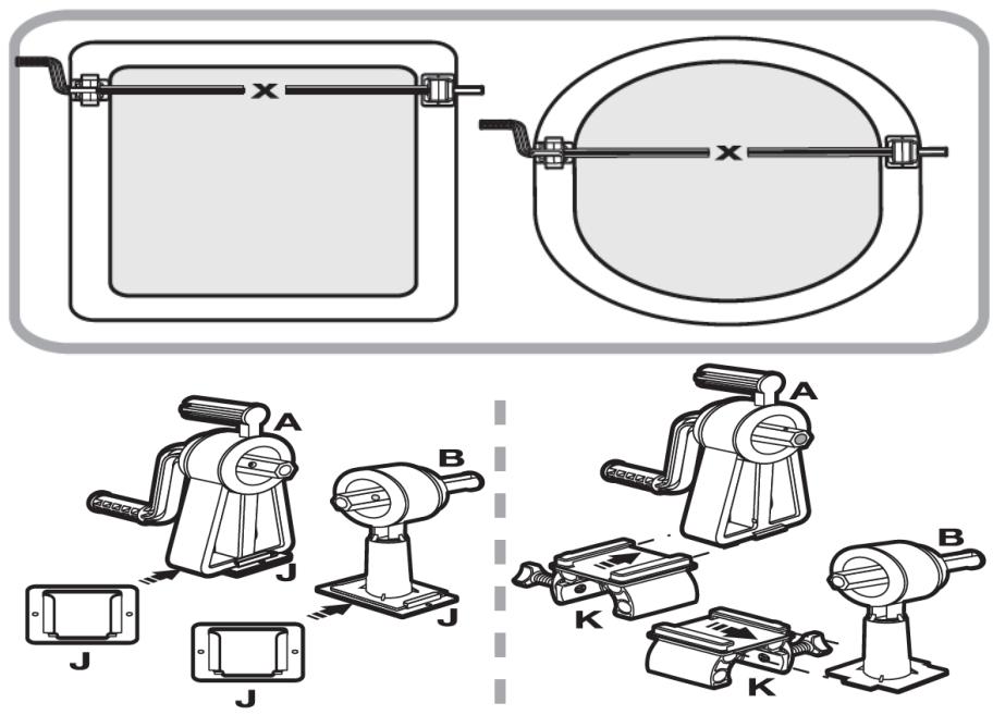
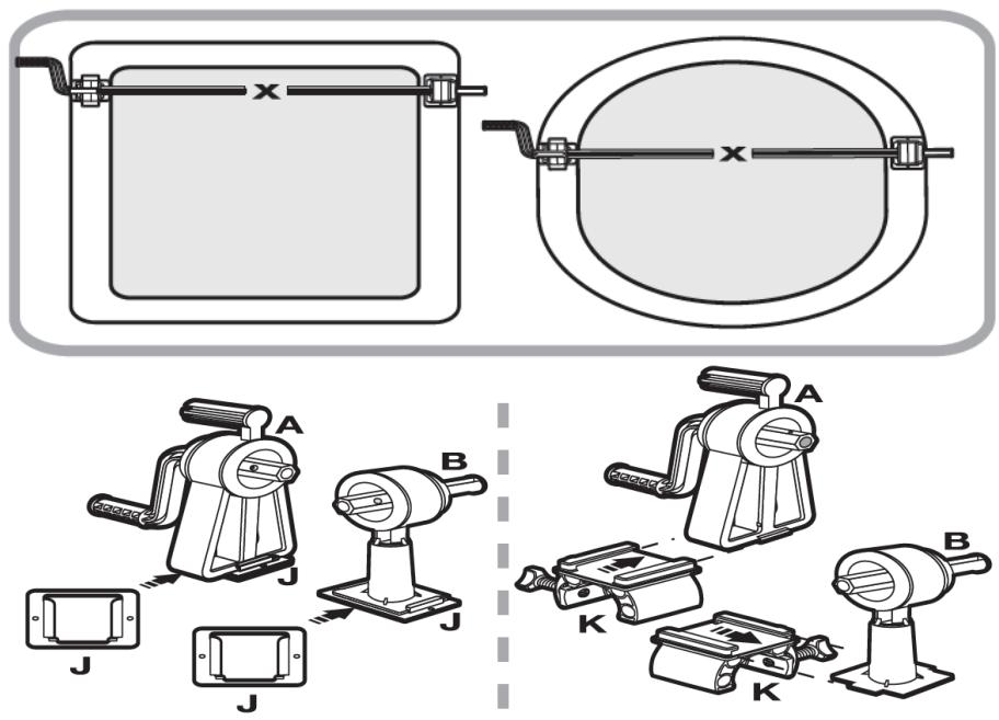
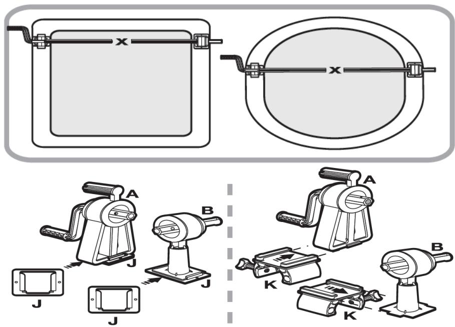
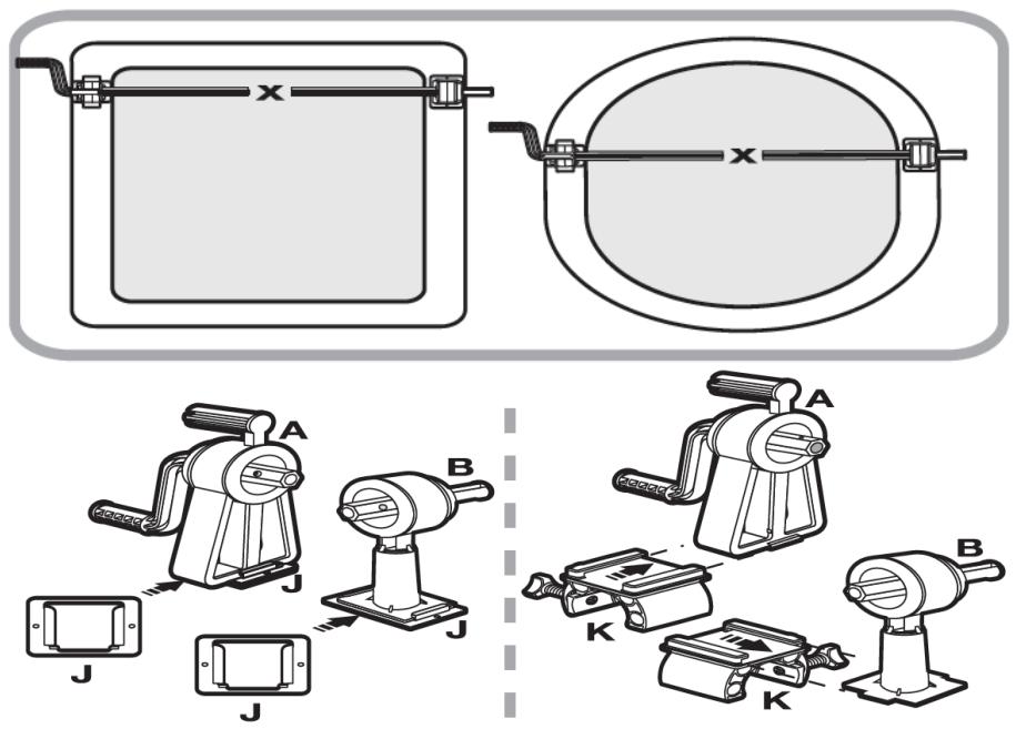
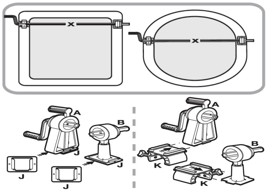
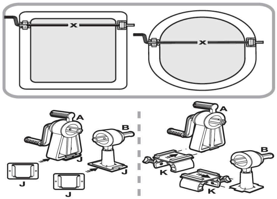
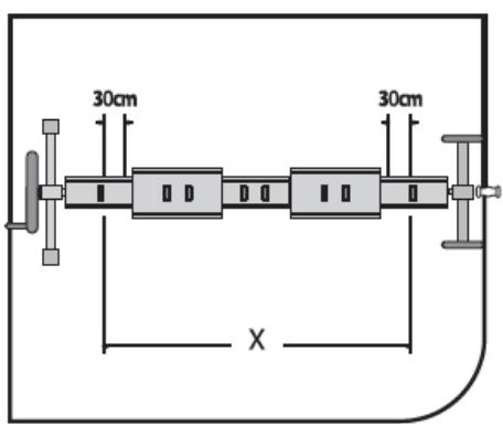
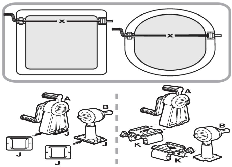
  3. (See fig. 26) The required roller length is marked as the distance X from the inside of the support (A) to the inside of the second support (B) when both supports are positioned on opposite sides of the pool.

To measure the distance X for flat-edge pools:

a) Insert the bases (J) into the bottoms of the supports (A) and (B).
b) Place the supports (A) and (B) on the edge.
c) Measure the distance between the inner sides of the supports (A) and (B).

To measure the distance X for pools with banks in the form of a tubular frame:

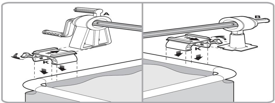
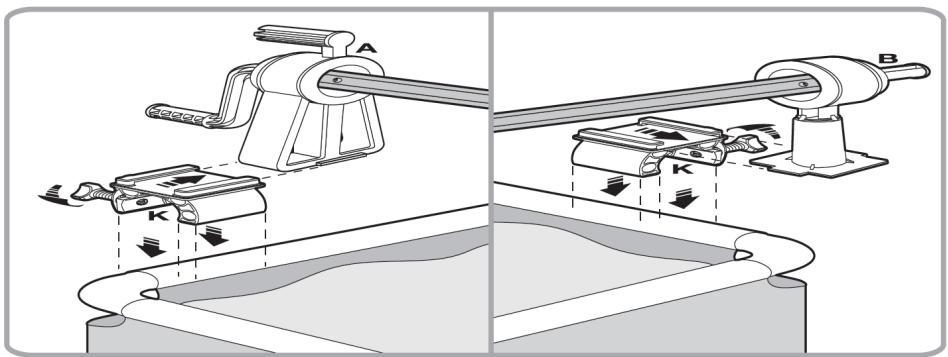
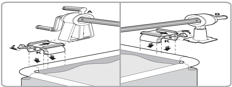
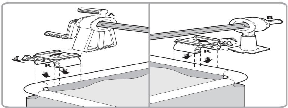
a) Insert the bases (K) into the bottoms of the supports (A) and (B).
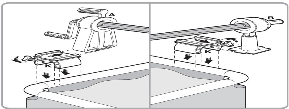
b) Place supports (A) and (B) on the tubular frame and secure their position by tightening the screws on the bases (K).
c) Measure the distance between the inner sides of the supports (A) and (B).

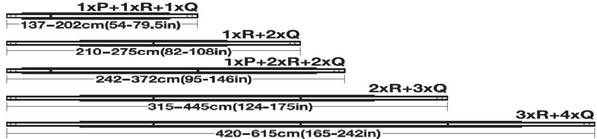
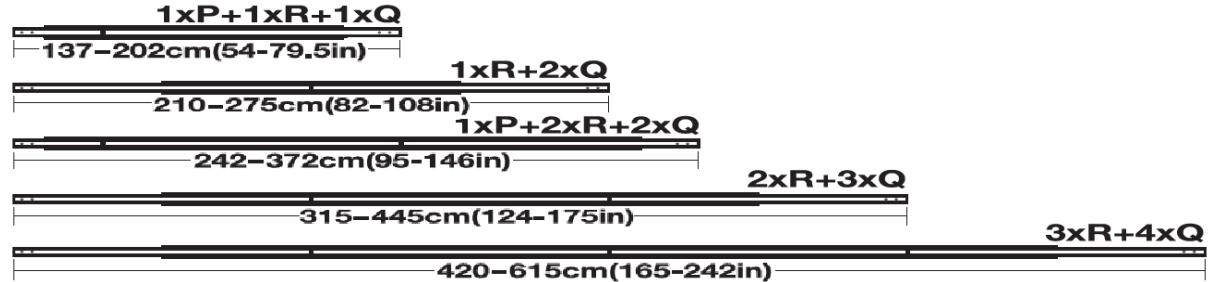
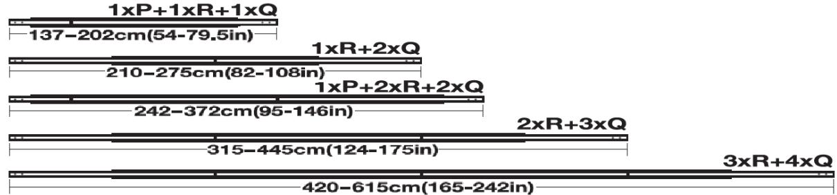
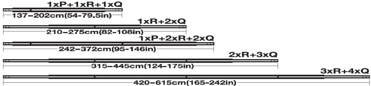
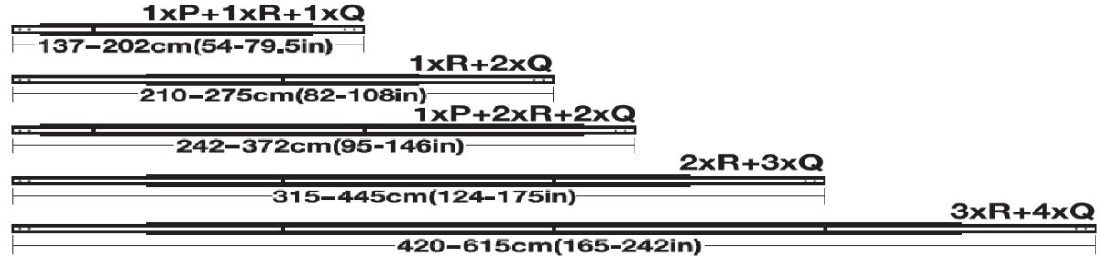
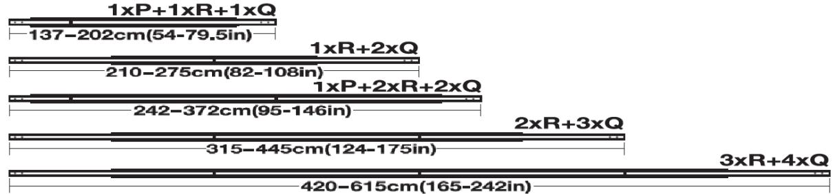
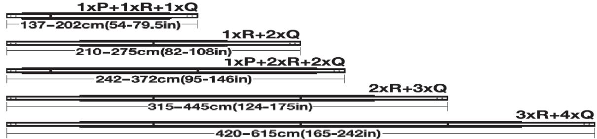
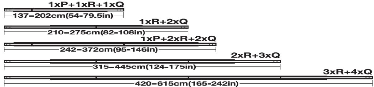
  1. (See fig. 27) Possible configuration of tube connection

PLEASE NOTE: The minimum overlap of pipes is 20 cm (8in)

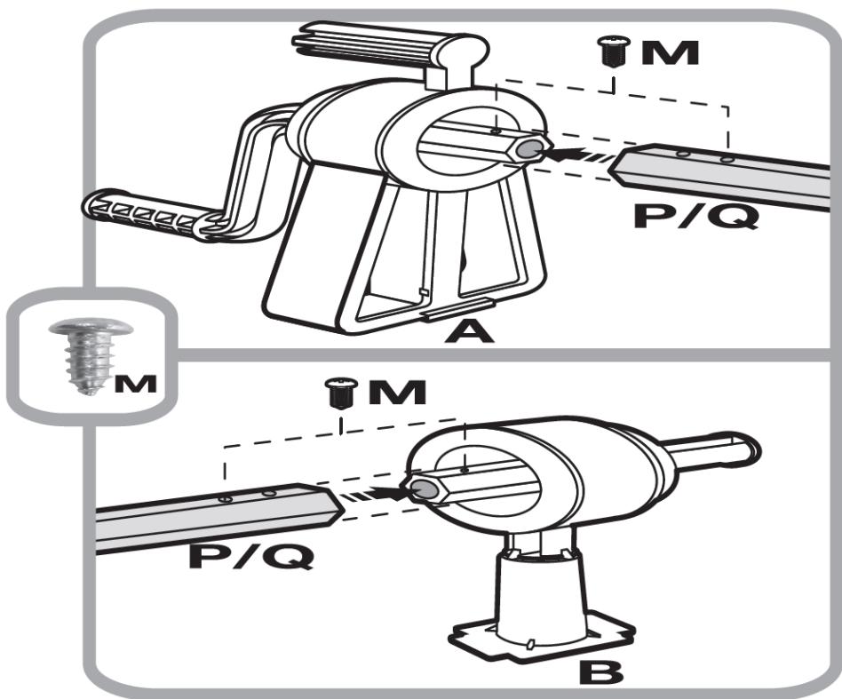
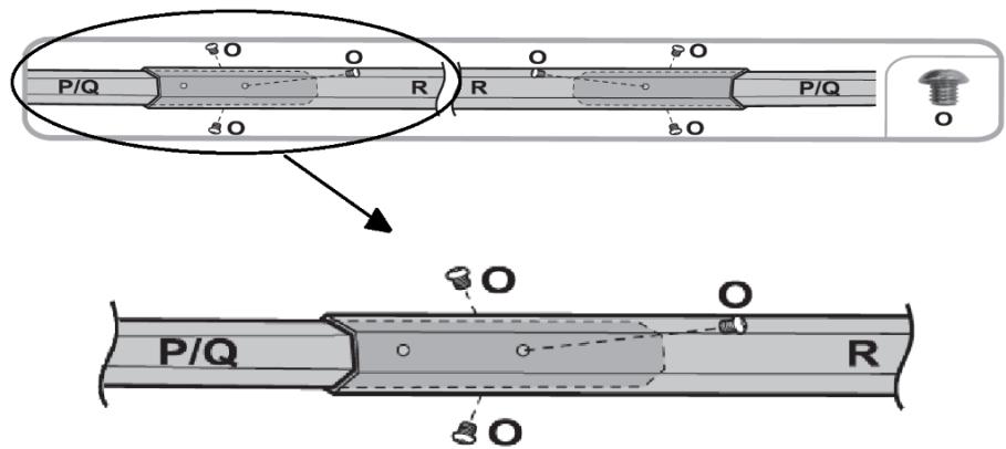
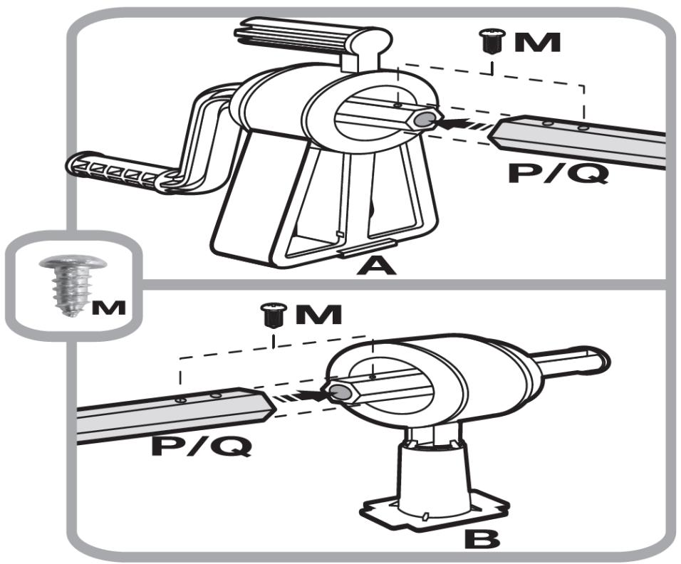
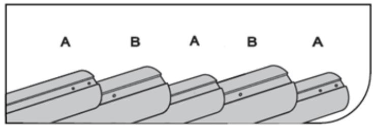
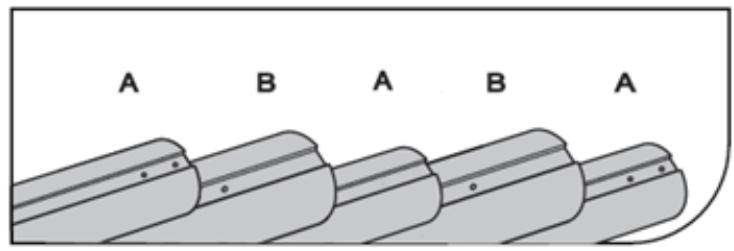
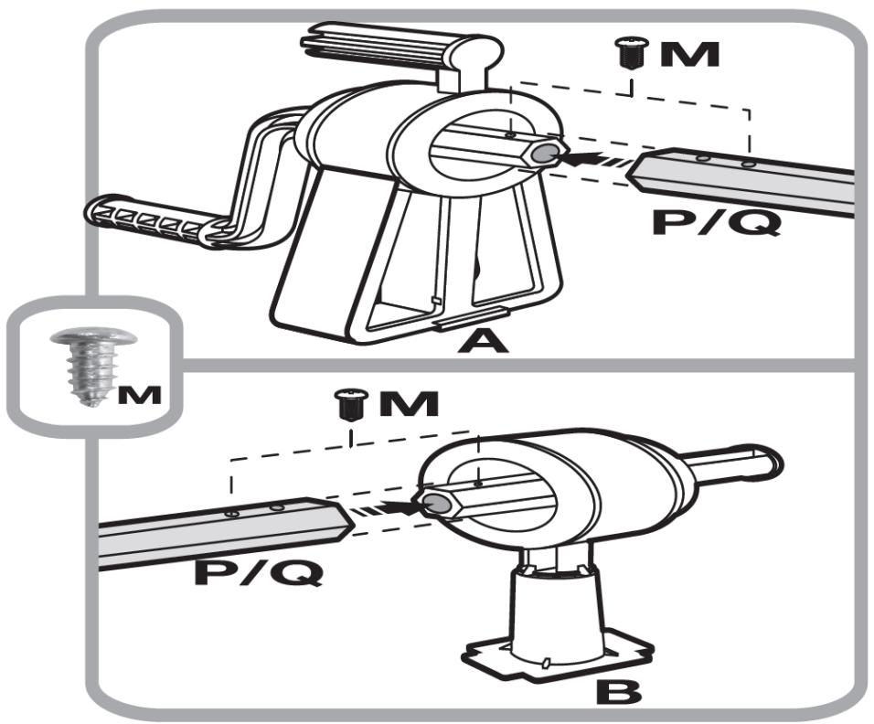
Openings in pipes (P and Q) should be located at the outer ends of the connected pipes to enable installation of both one support (A) and the other support (B).

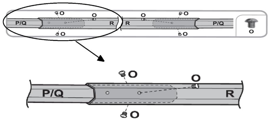
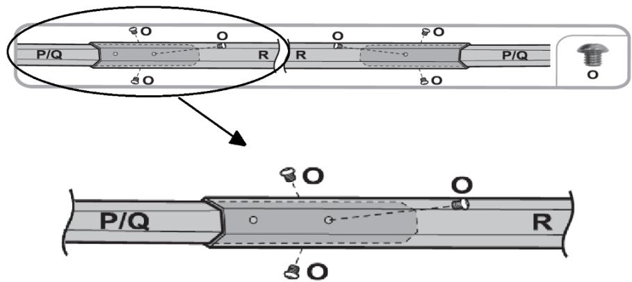
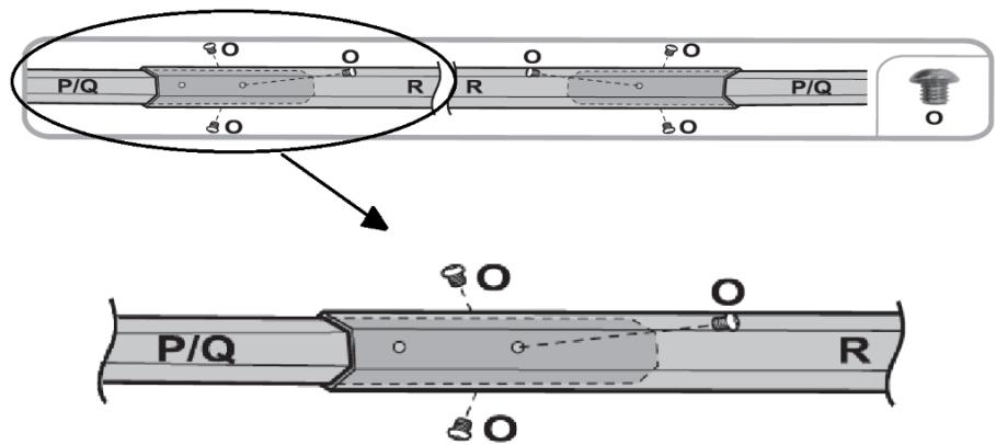
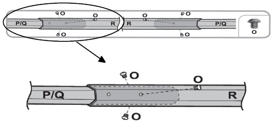
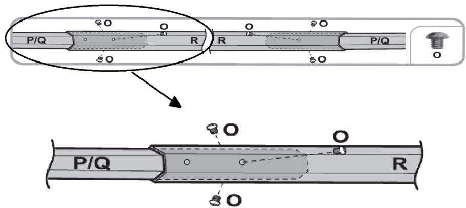
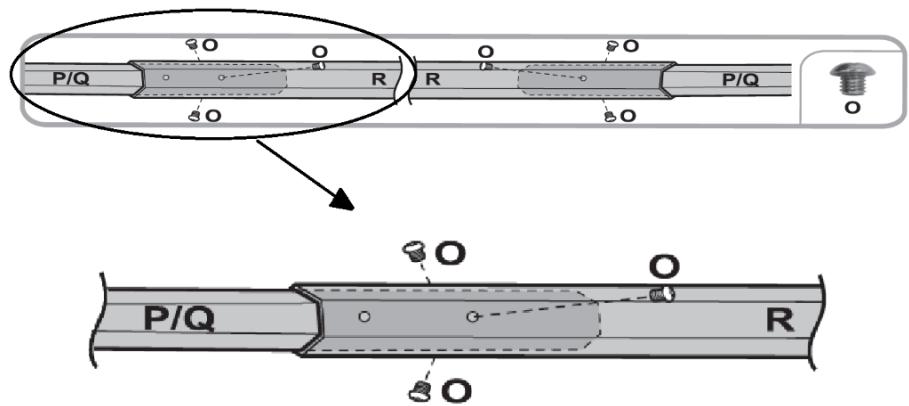
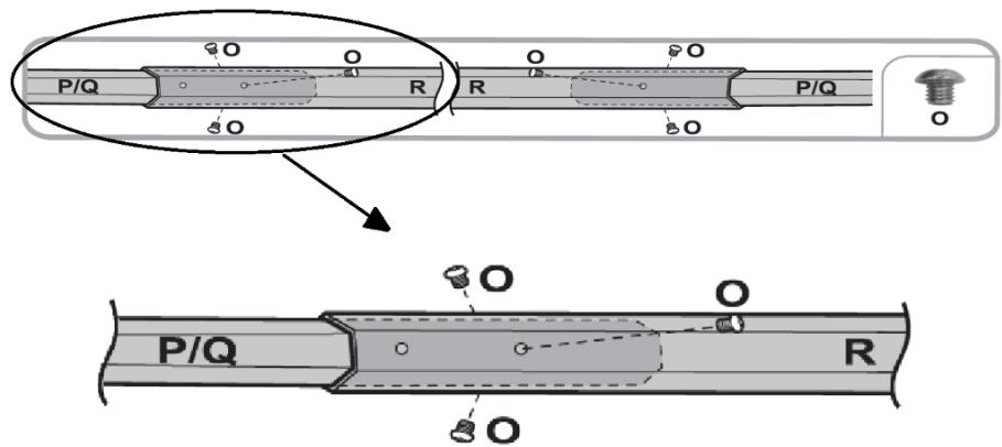
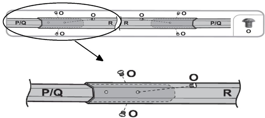
  1. (See fig. 28) To secure the connection of one pipe (R) to another pipe (P or Q), screw the screws (O) into the holes on the pipe (R). Keep the minimum overlap of the tubes 20cm (8in).
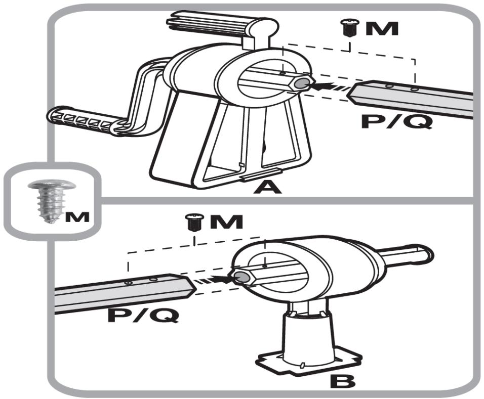
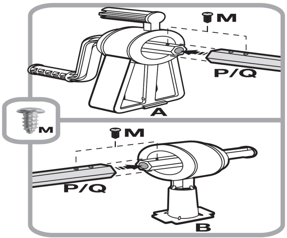
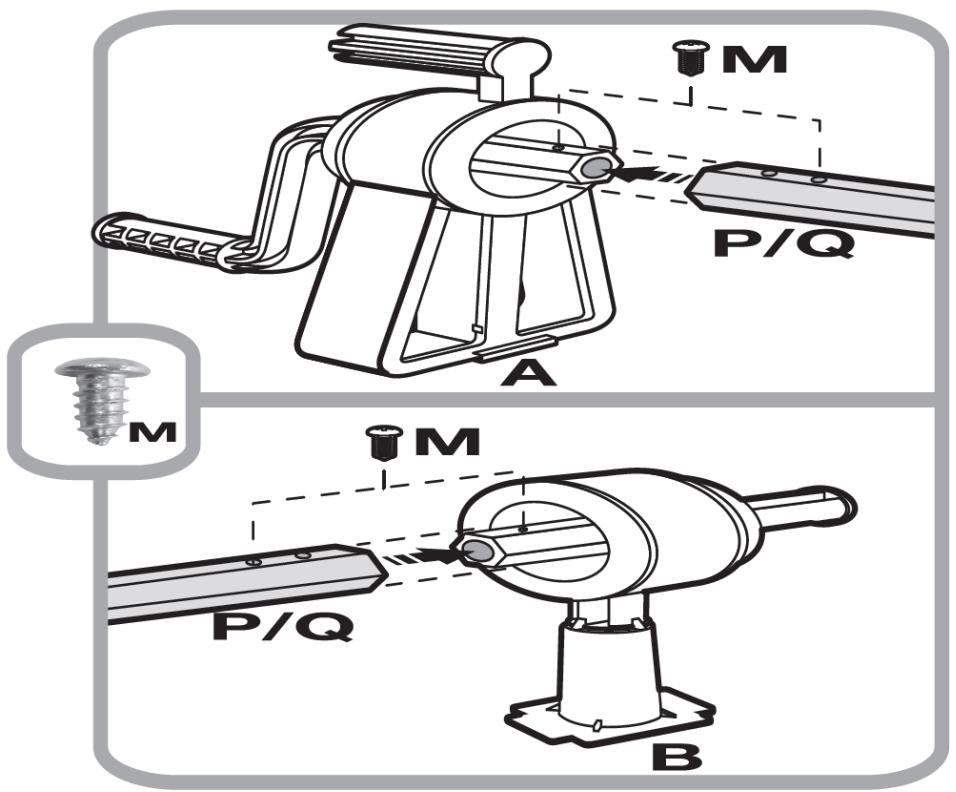
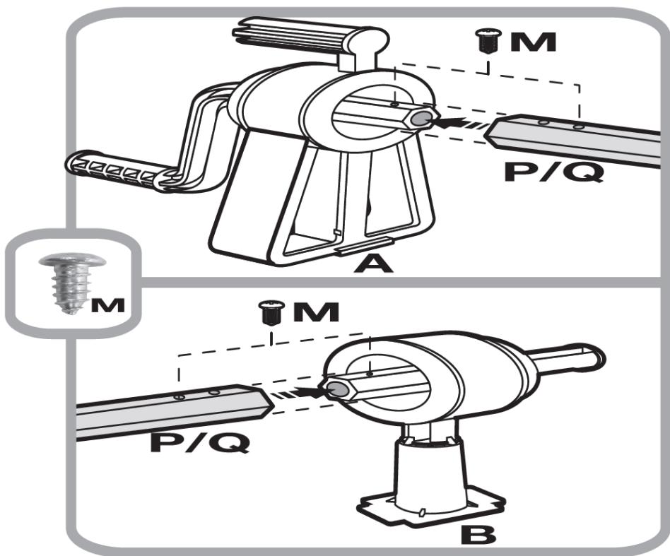
  2. (See fig. 29) After connecting the tubes, they should be mounted on the support axles (A and B). It must be ensured that the second opening on the pipe (P and Q) and the hole in the support axis are in the same position to allow the screw (M) to be installed. Secure the connection with the screw (M).

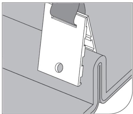
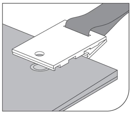
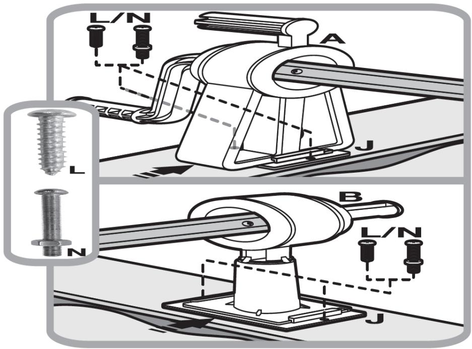
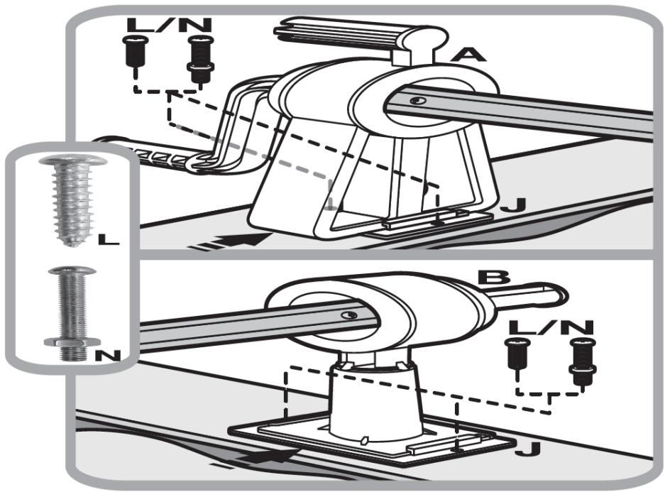
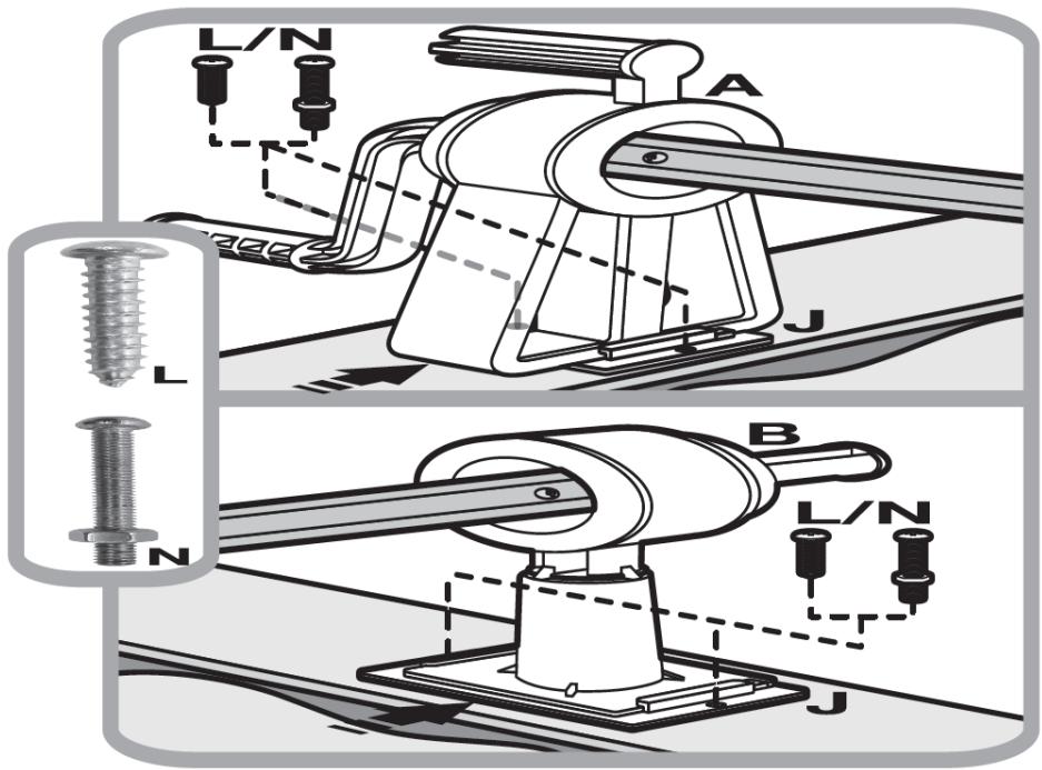
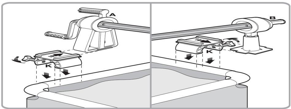
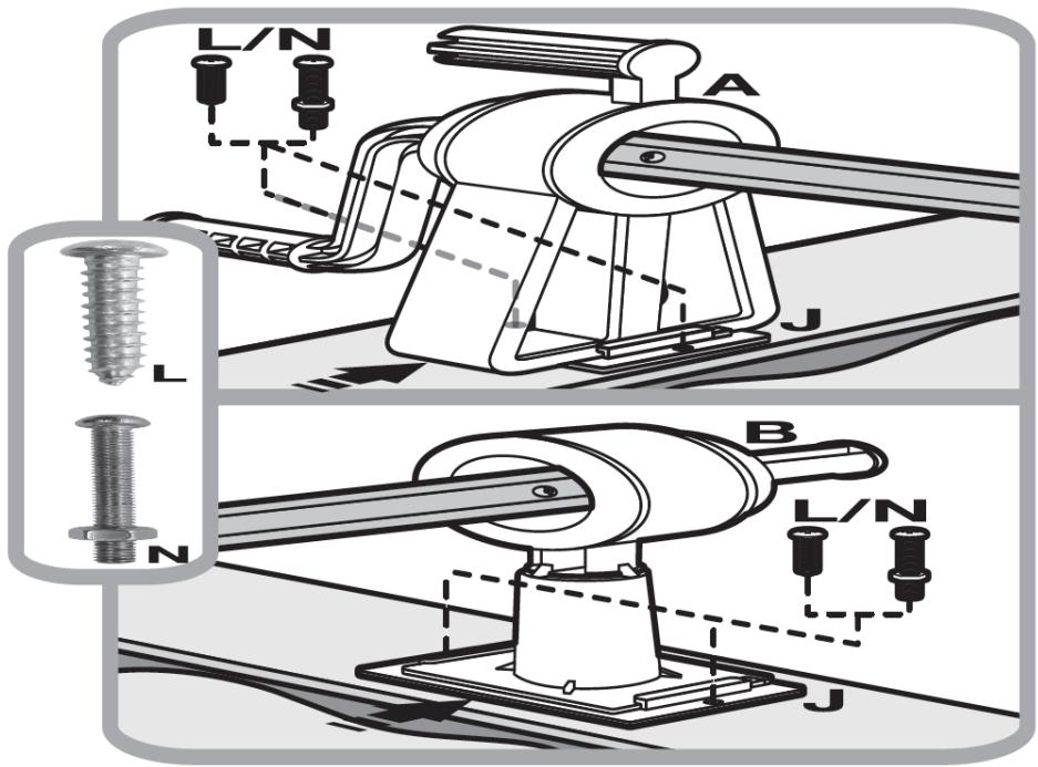
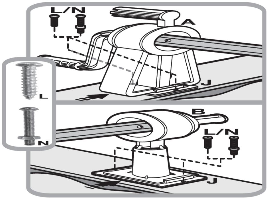
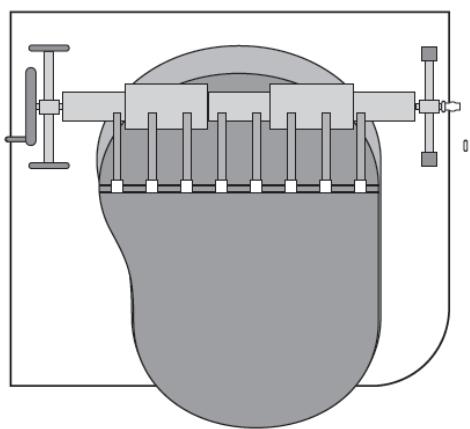
  3. (See fig. 30) Position the roller supports (A and B) together with the base (J) on the edge of the pool.

In case the edge is made of plastic or wood, use self-tapping screws (L) to fix the base (J) to the edge. In the case where the edge is made of metal, first drill holes corresponding to the size of the opening in the base (J). Secure the position of the support with the base by screwing it to the edge with a screw and a nut (N).

If it is necessary to increase the length of the roller, loosen the three screws (O) on the tube (R) at both ends of the roller. Adjust the length of the roller and tighten the screws (O) to secure the connection.

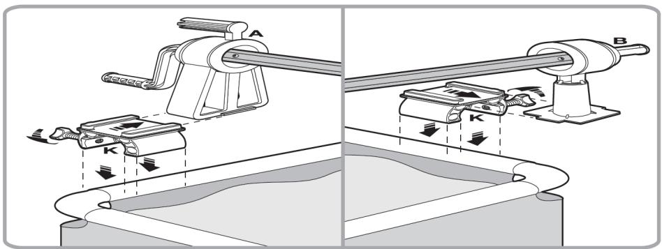
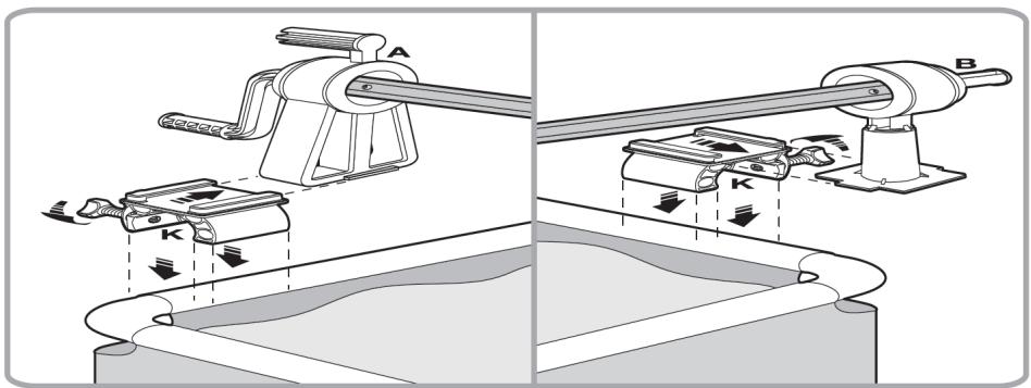
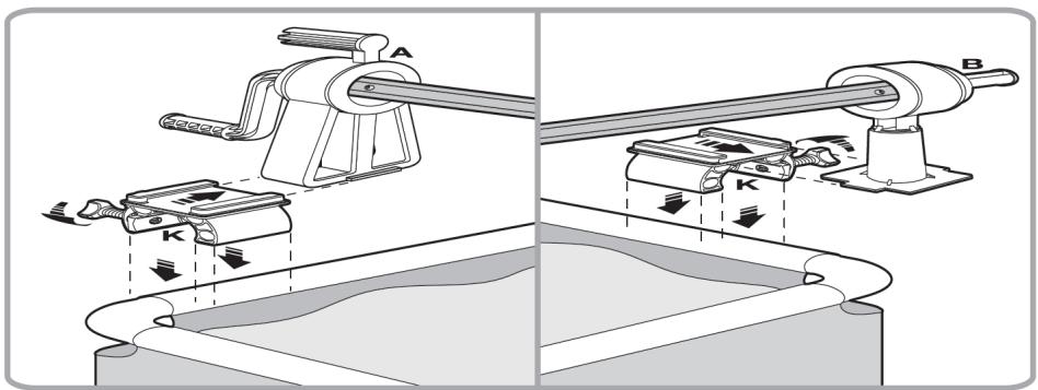
  1. (See fig. 31) For pools with a tubular frame

Position the roller supports (A and B) together with the base and the holder (K) on the frame and tighten the screws in the base with the holder (K) so that the supports (A and B) are in a stable position.

If it is necessary to increase the length of the roller, loosen the three screws (O) on the tube (R) at both ends of the roller. Adjust the length of the roller and tighten the screws (O) to secure the connection.

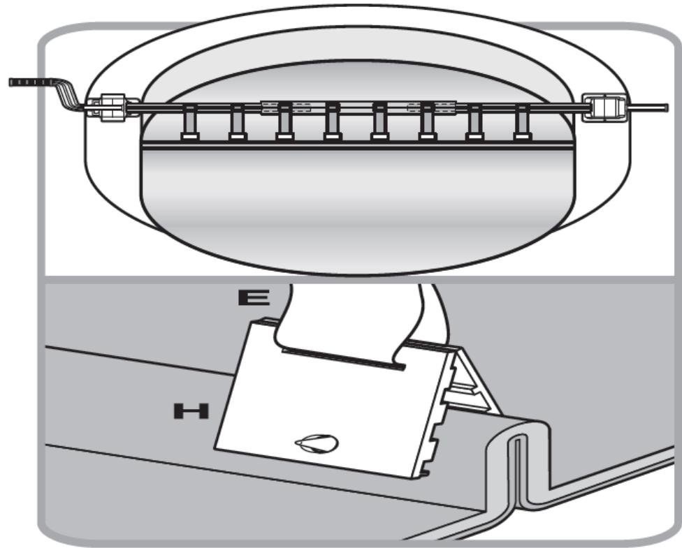
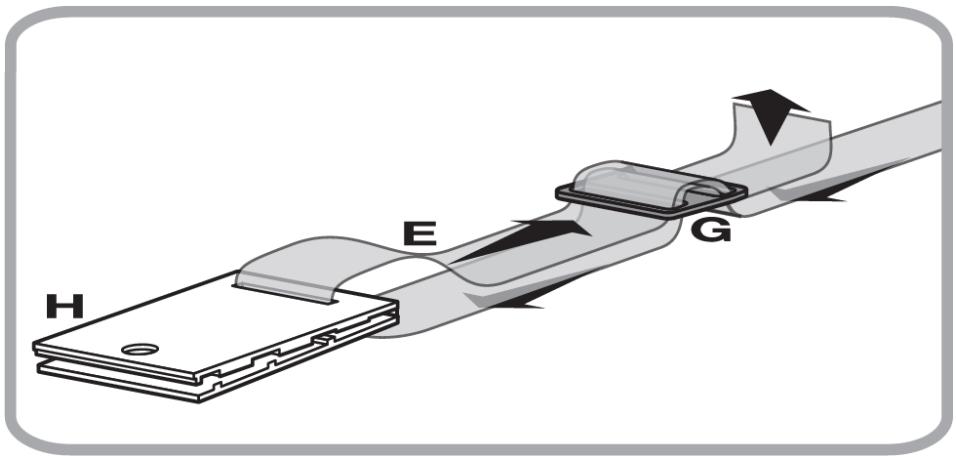
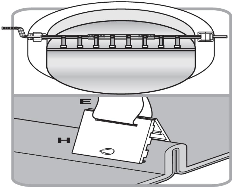
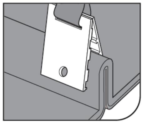
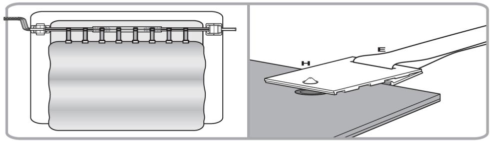
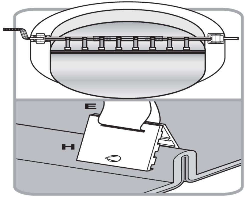
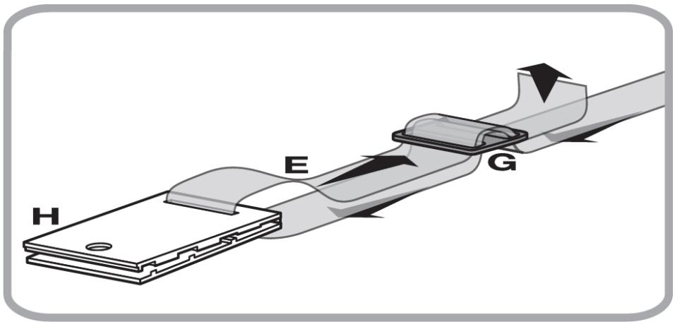
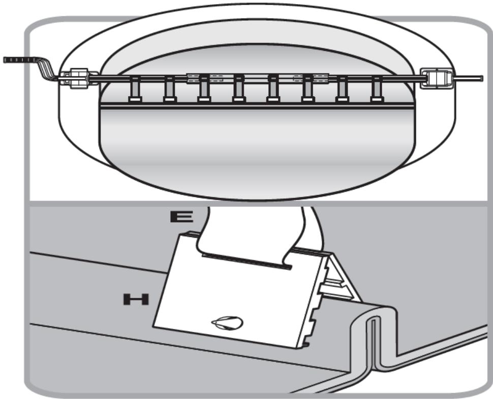
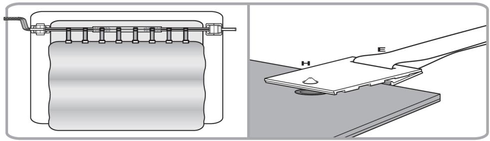
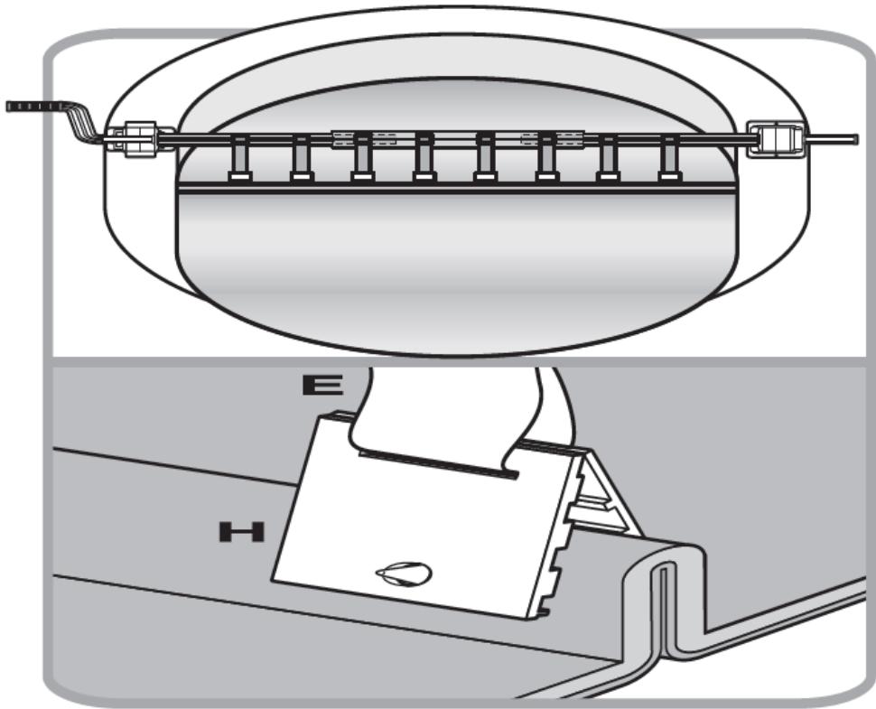
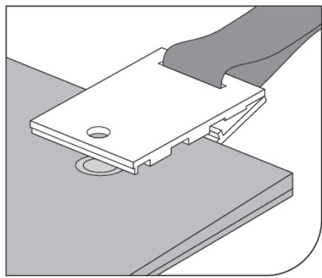
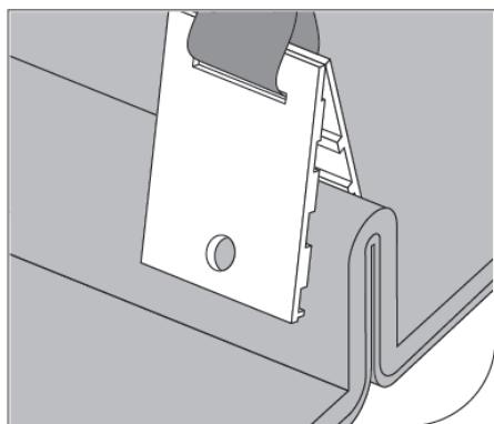
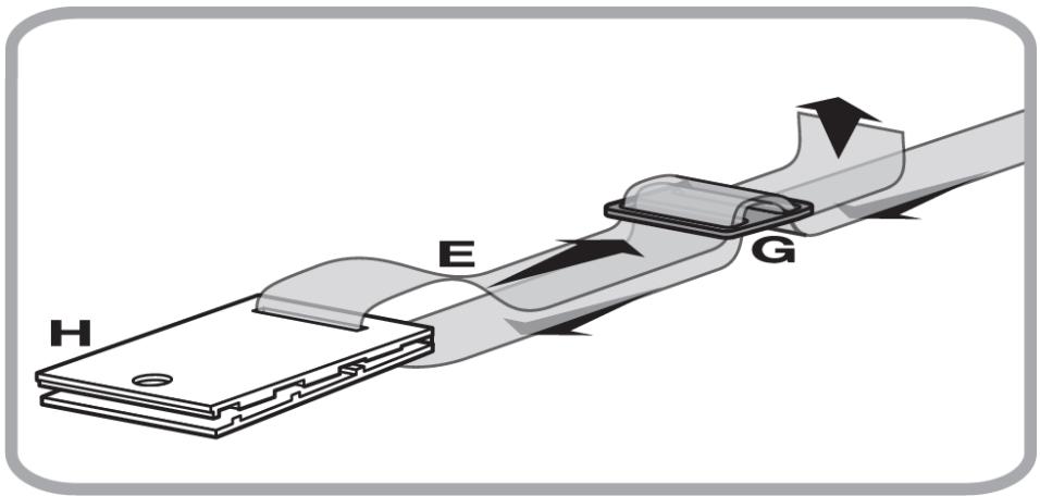
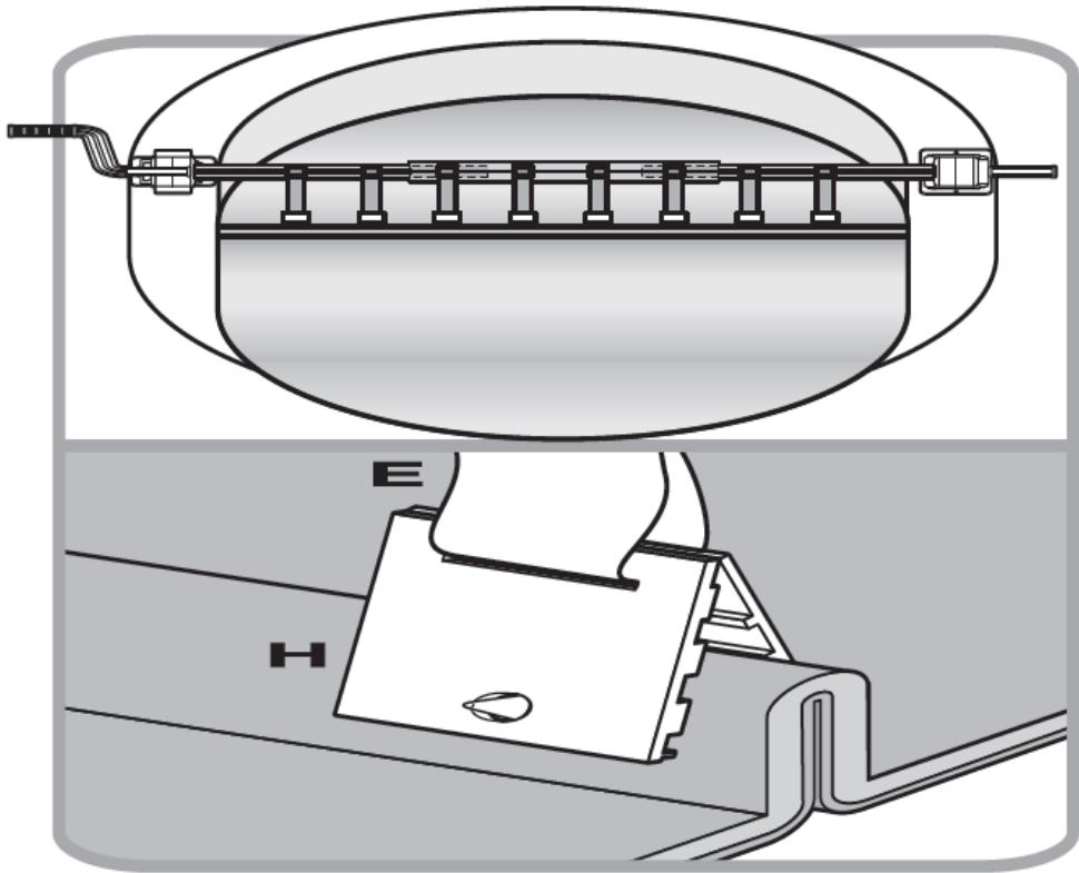
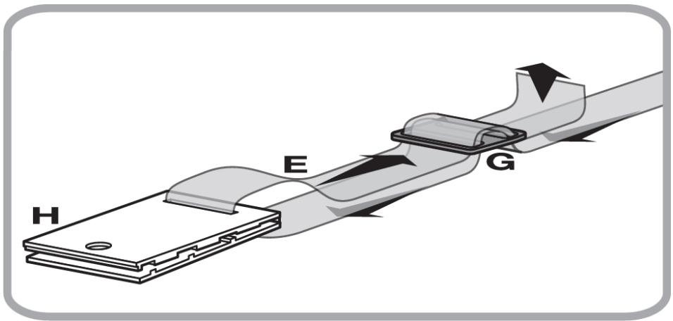
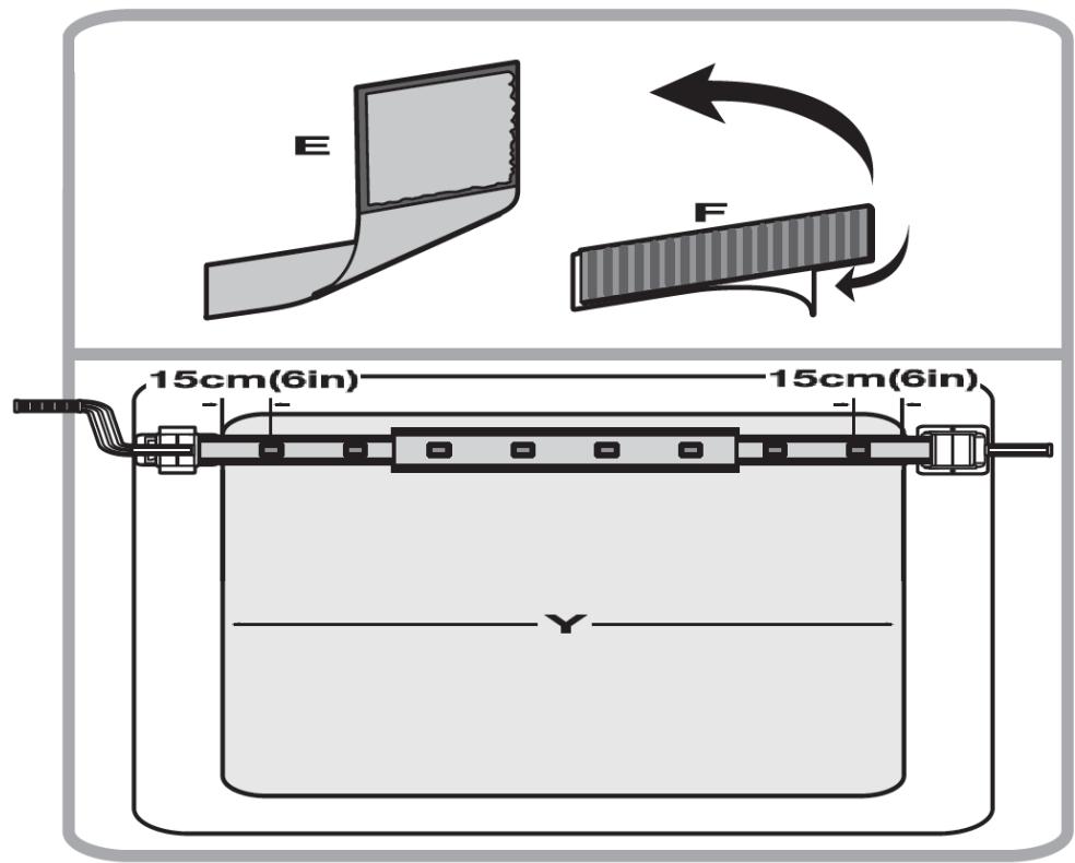
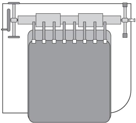
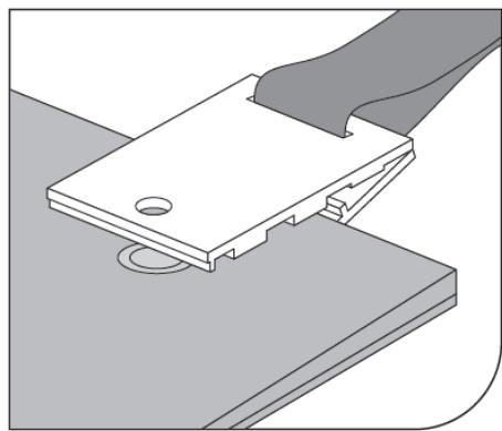
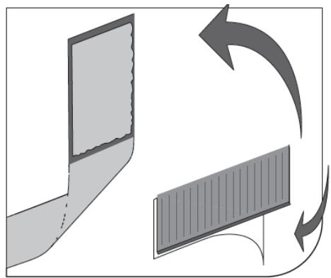
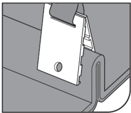
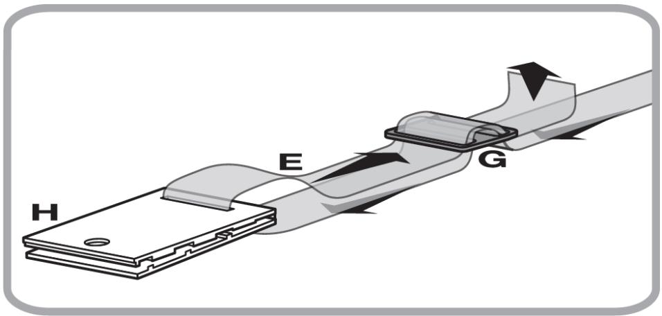
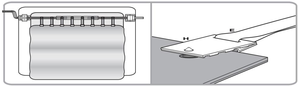
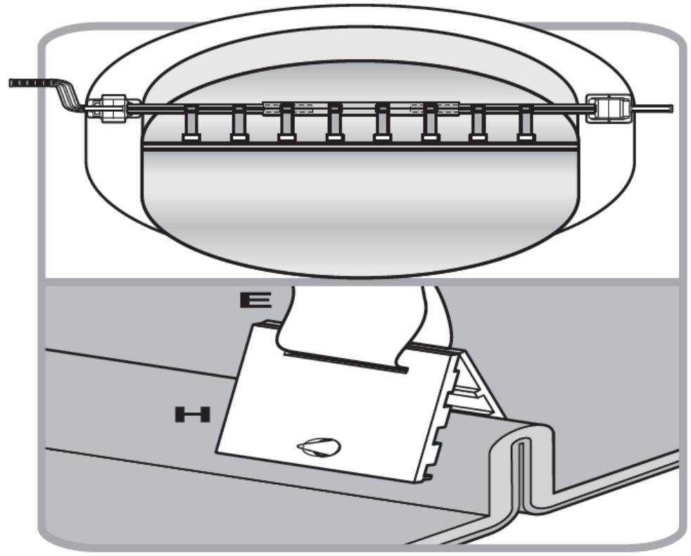
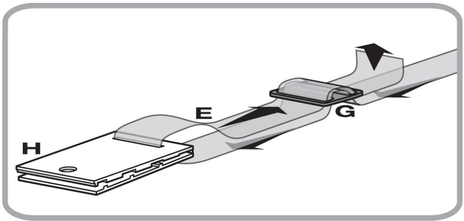
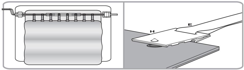
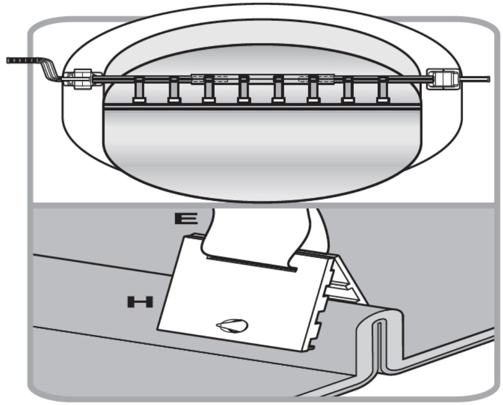
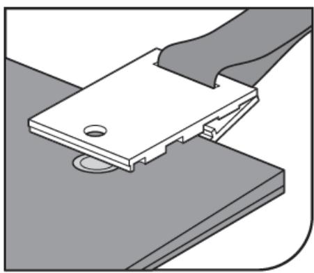
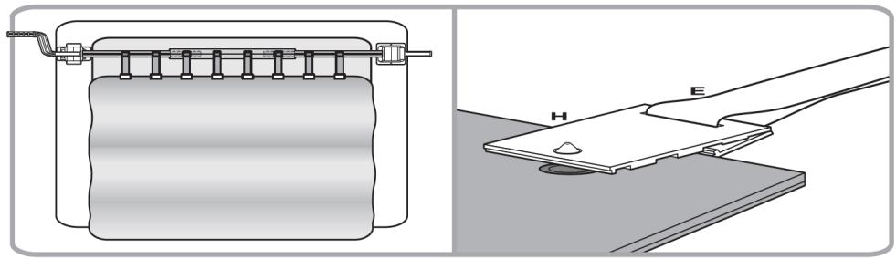
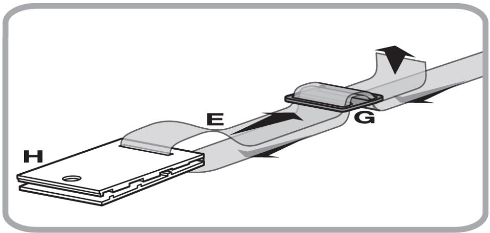
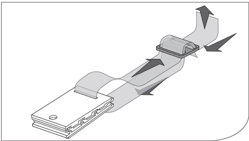
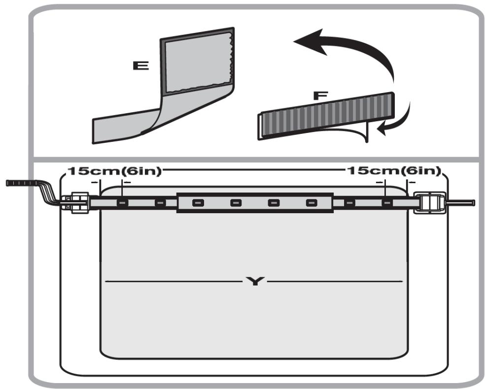
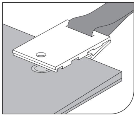
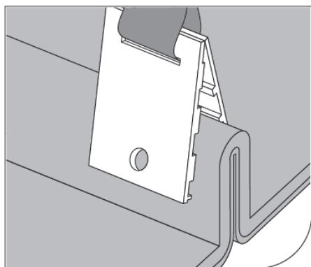
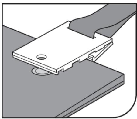
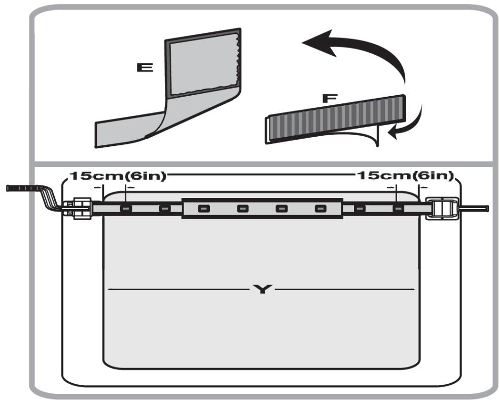
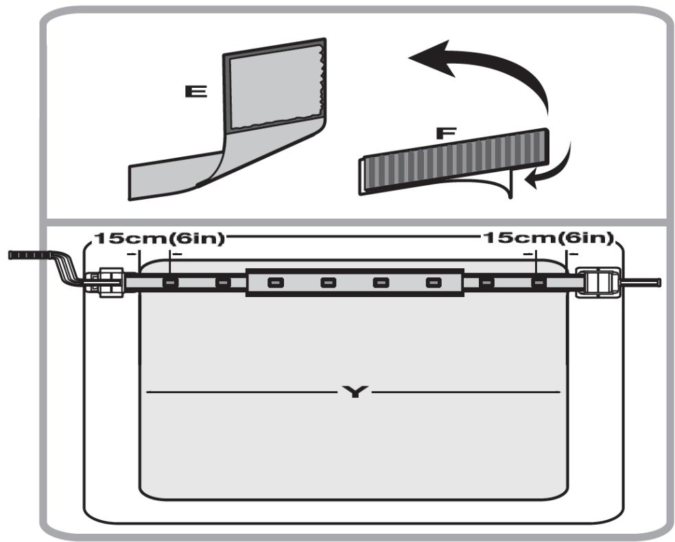
  1. (See fig. 32) Connect the strap (E), the clamp (G) and the clip (H).

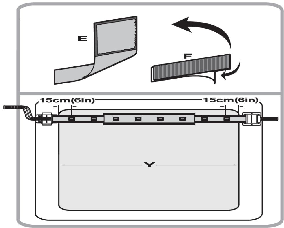
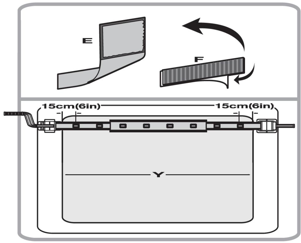
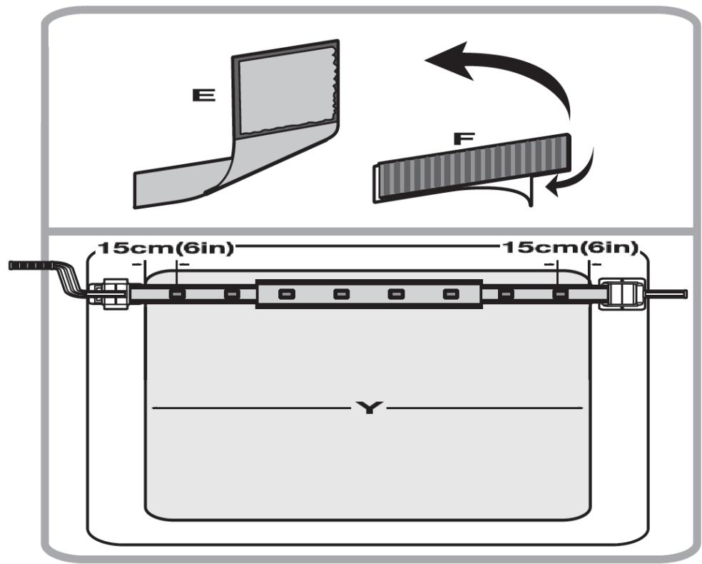
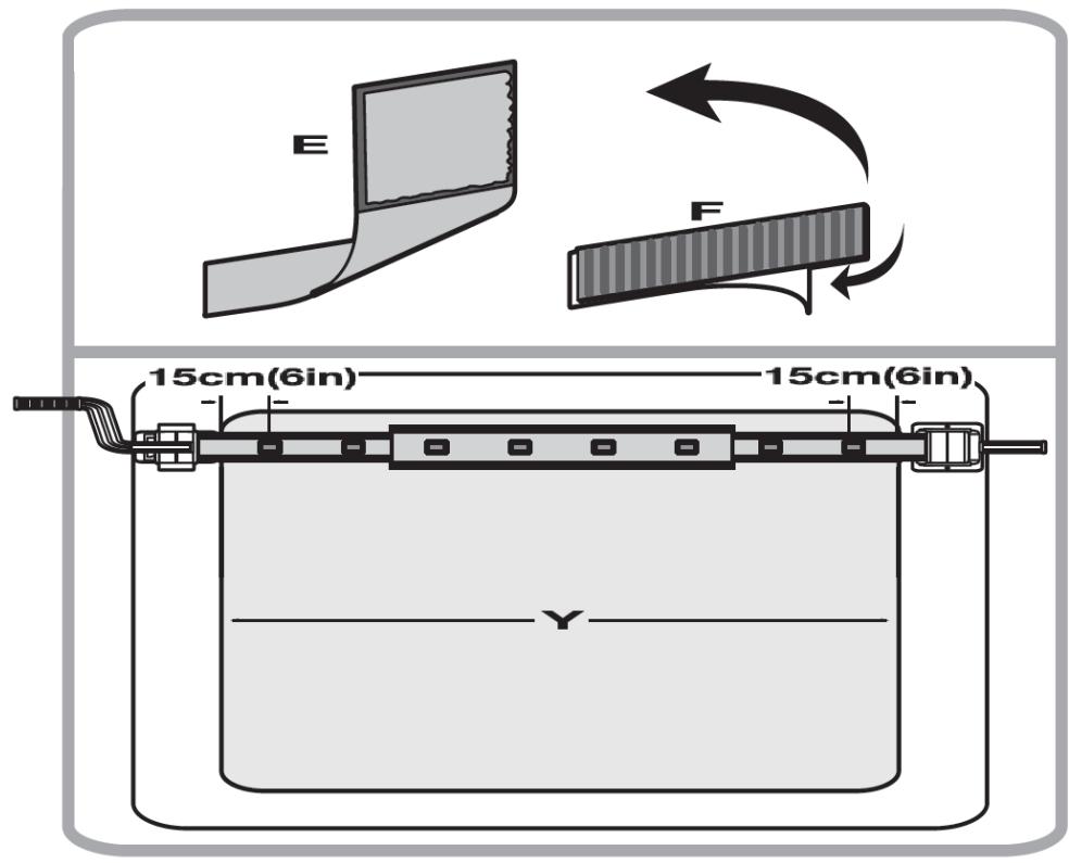
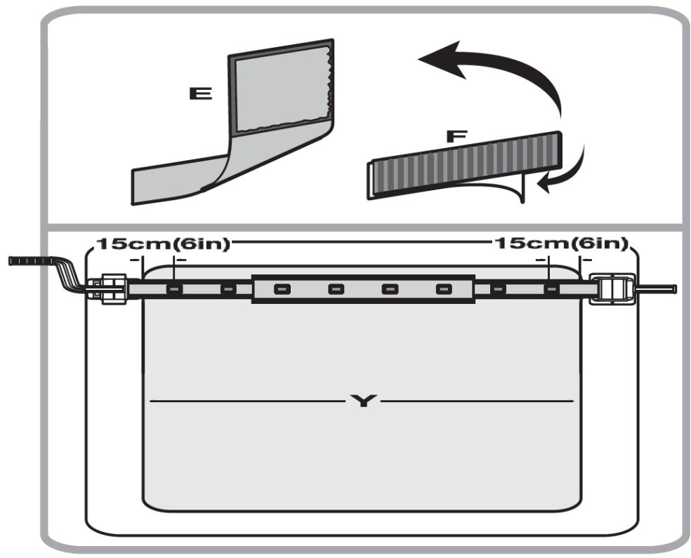
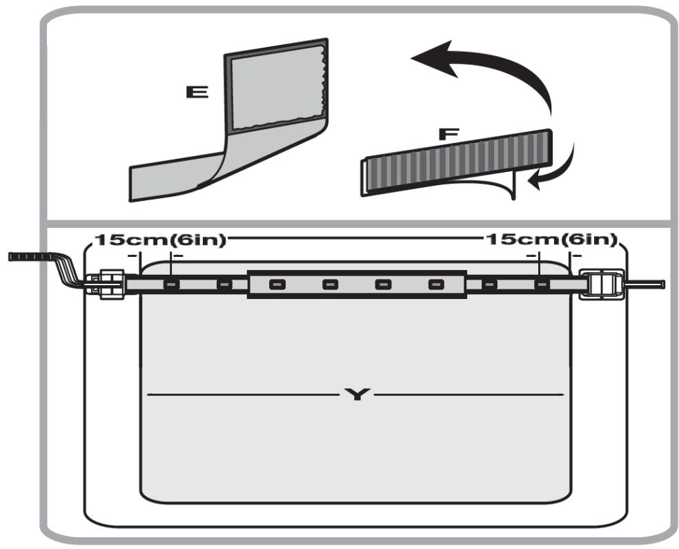
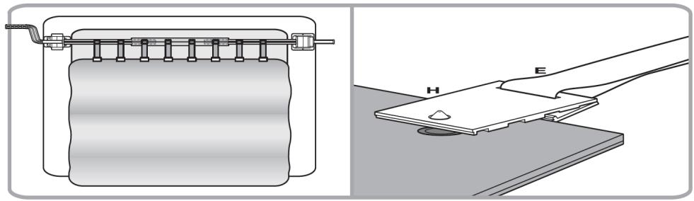
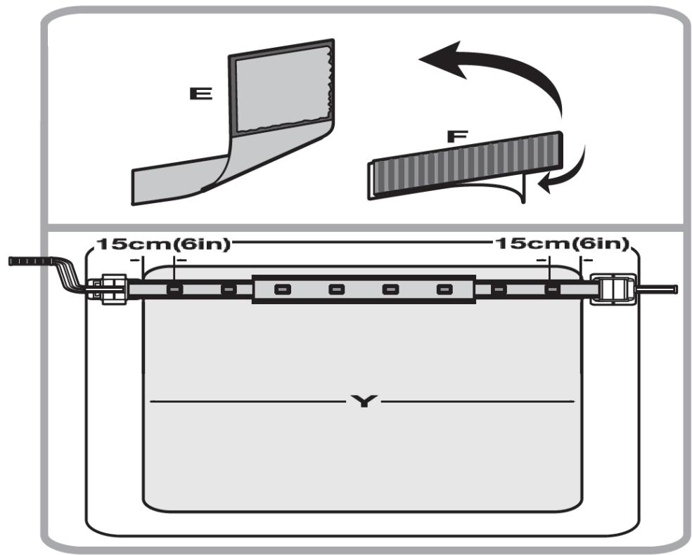
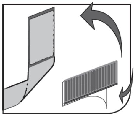
  2. (See fig. 33) Disconnect the male Velcro parts (F) from the strap (E) and remove the adhesive layer from the male part of the Velcro. Place the male Velcro parts (F) on the roller, perpendicular to its axle at regular intervals, along the entire length of the pool.

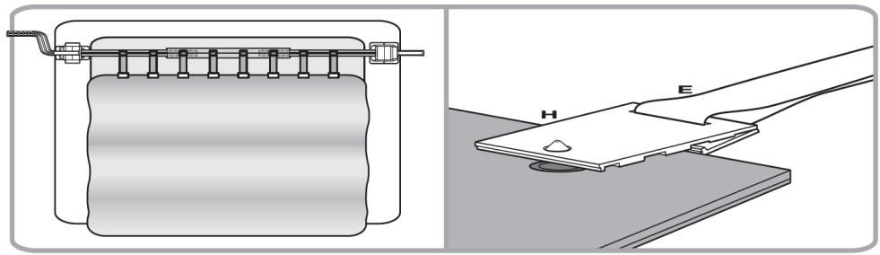
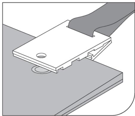
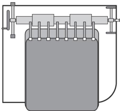
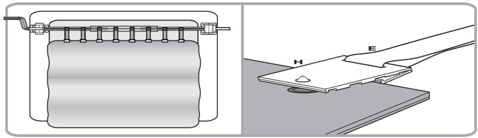
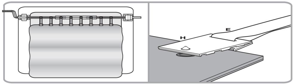
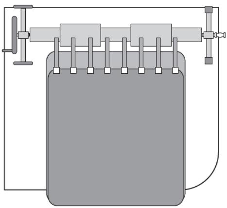
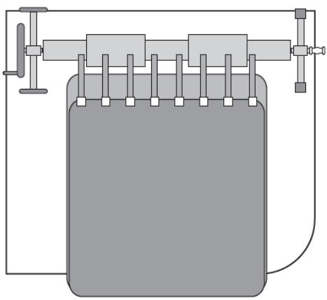
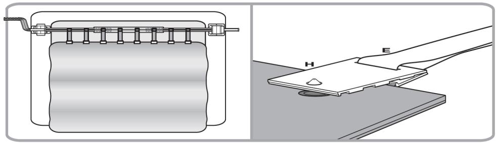
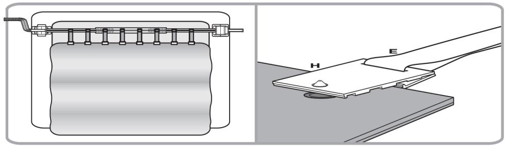
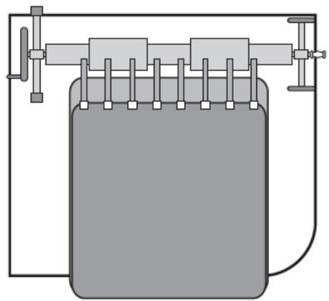
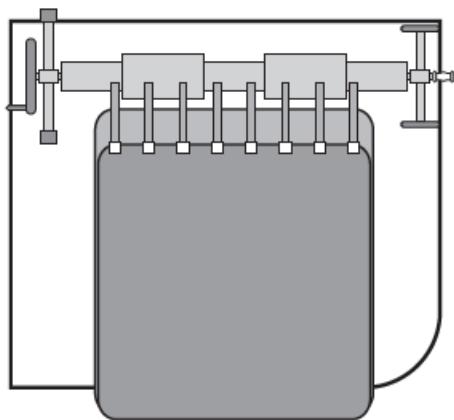
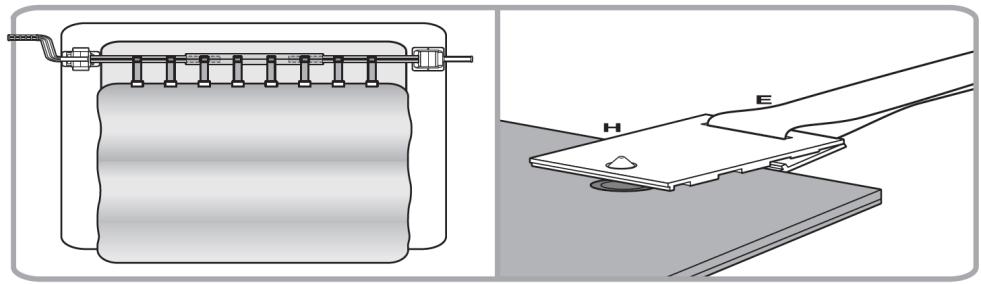
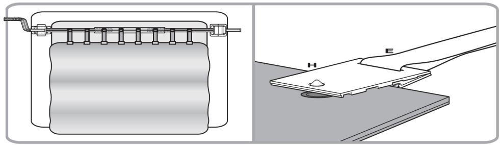
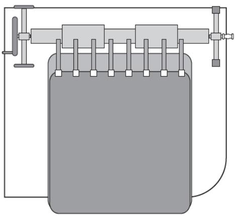
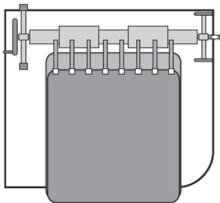
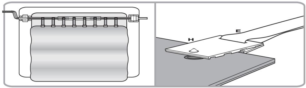
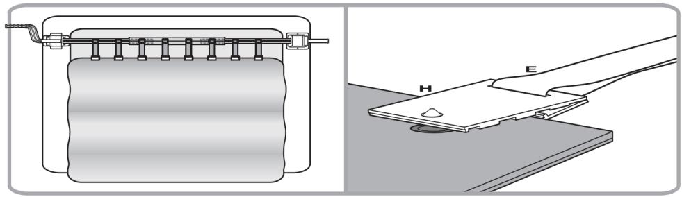
  3. (See fig. 34) In the case of rectangular pools:

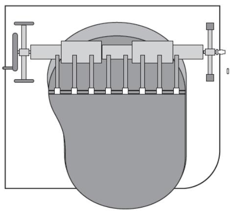
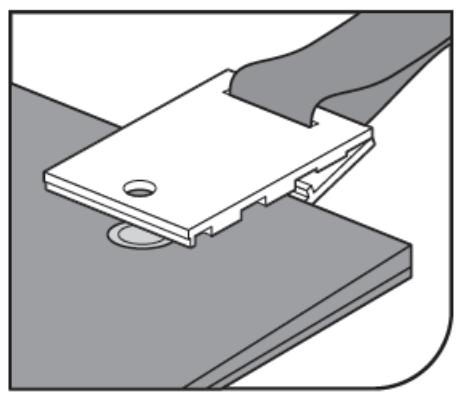
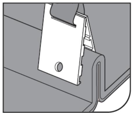
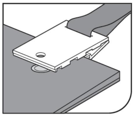
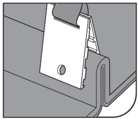
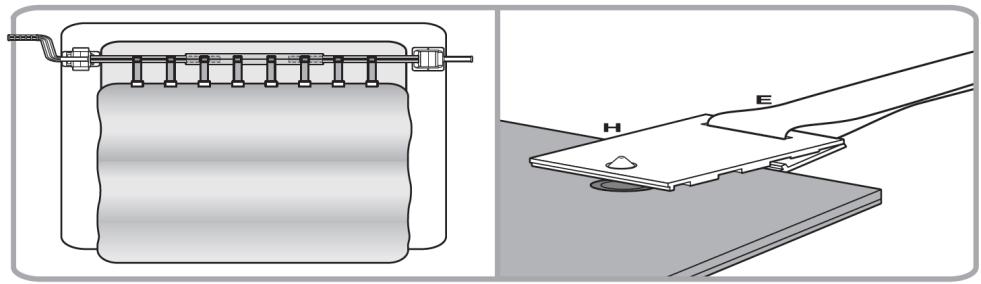
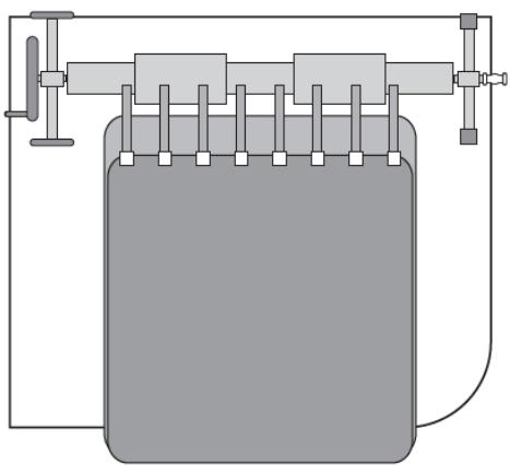
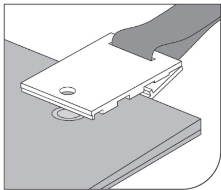
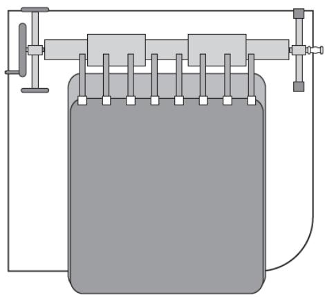
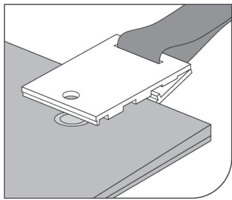
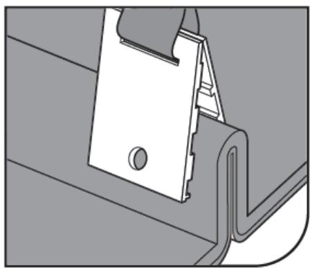
Spread the cover over the pool. Mount the clips (H) (as shown in the figure) to cover, at regular intervals, at a distance as the male Velcro parts (F) on the roller. Ensure that the length of the straps allows covering to lie flat on the pool surface to prevent air from blowing under the cover.

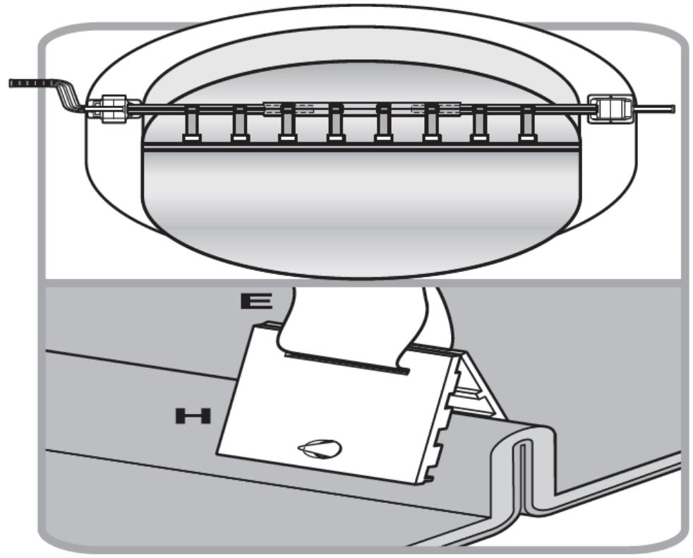
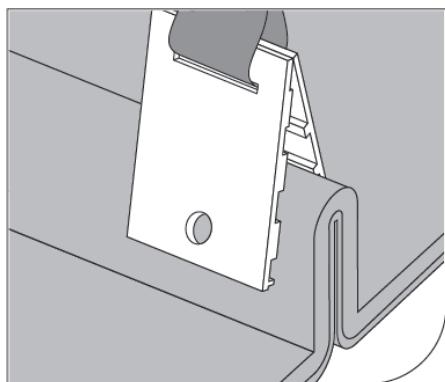
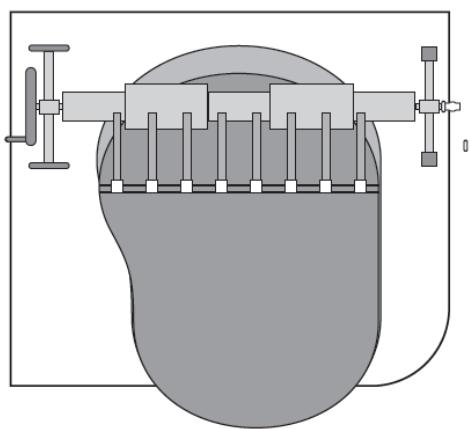
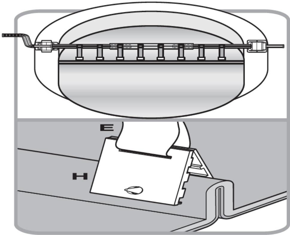
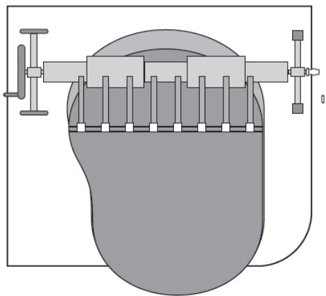
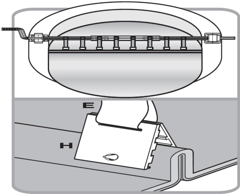
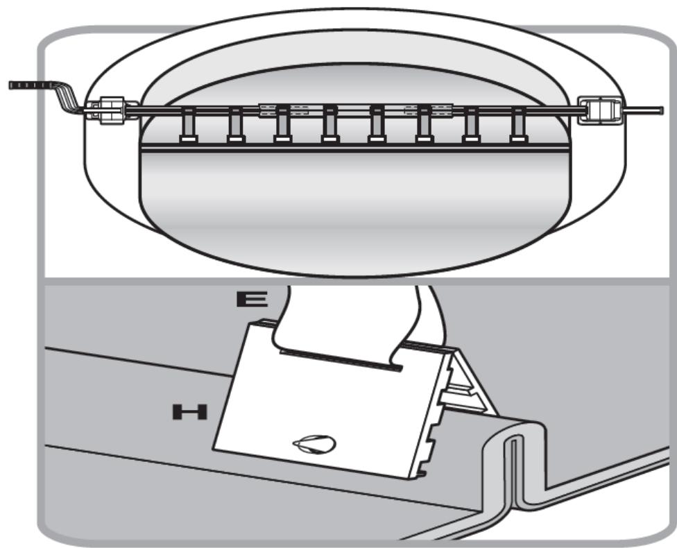
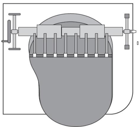
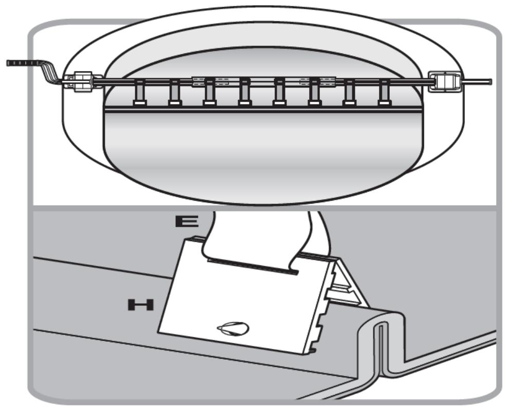
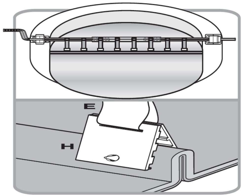
  1. (See fig. 35) For round or oval pools:

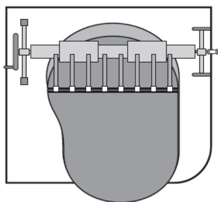
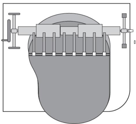
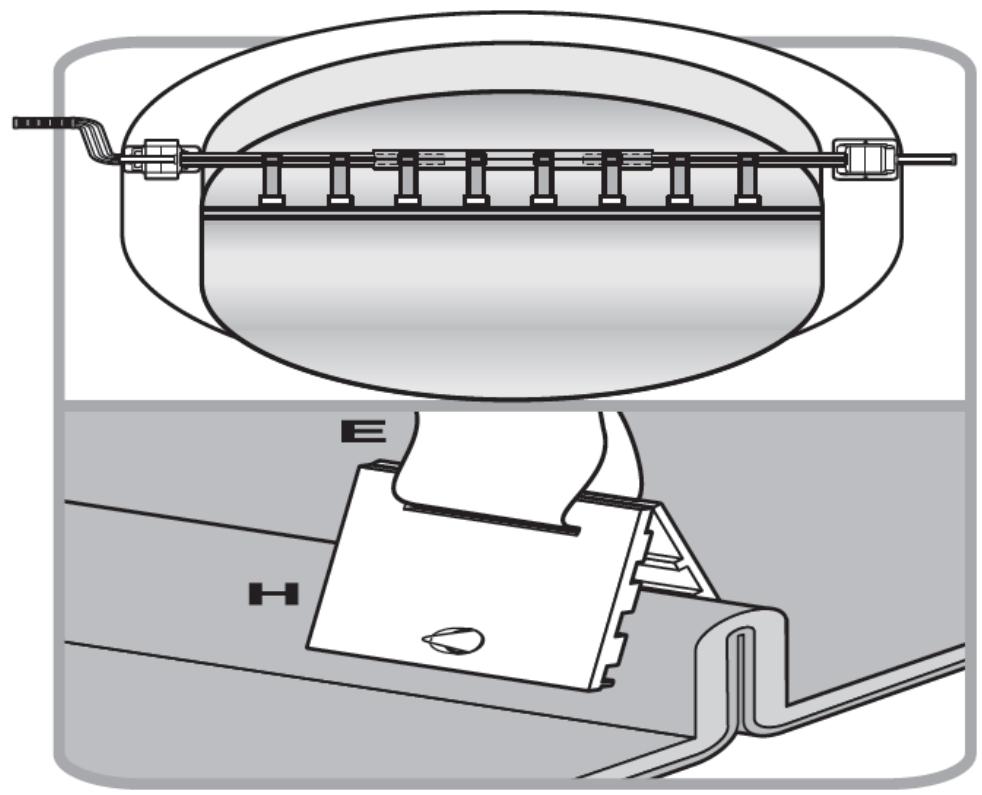
Spread the cover over the pool. Mount the clips (H) (as shown in the figure) to cover, at regular intervals, at a distance as the male Velcro parts (F) on the roller. Ensure that the length of the straps allows covering to lie flat on the pool surface to prevent air from blowing under the cover.

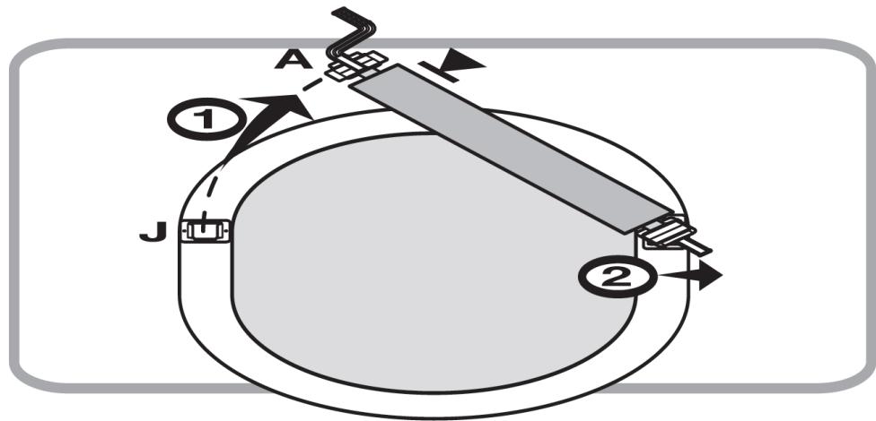
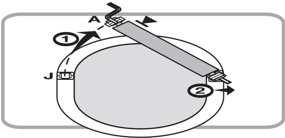
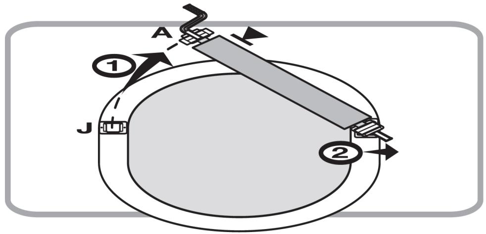
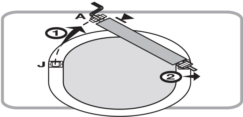
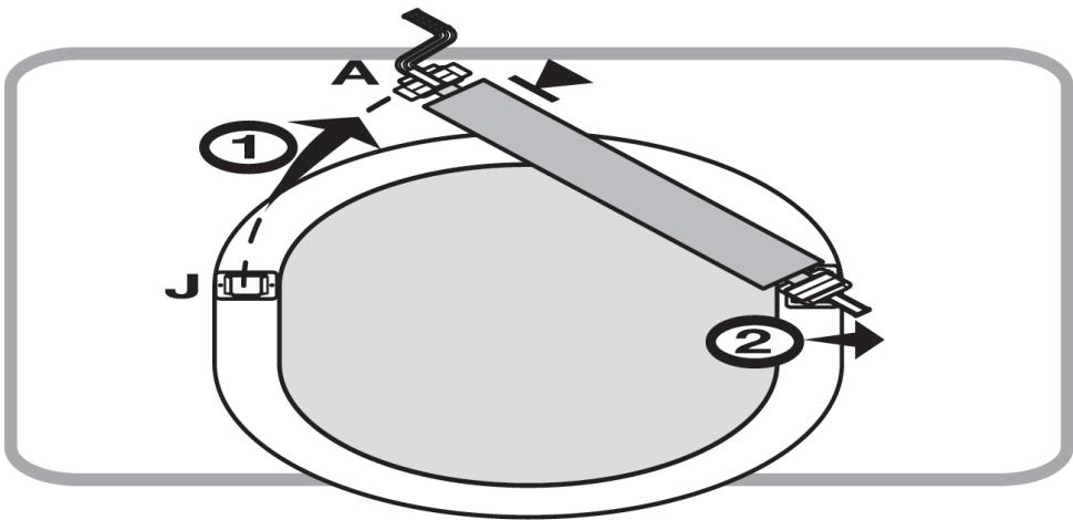
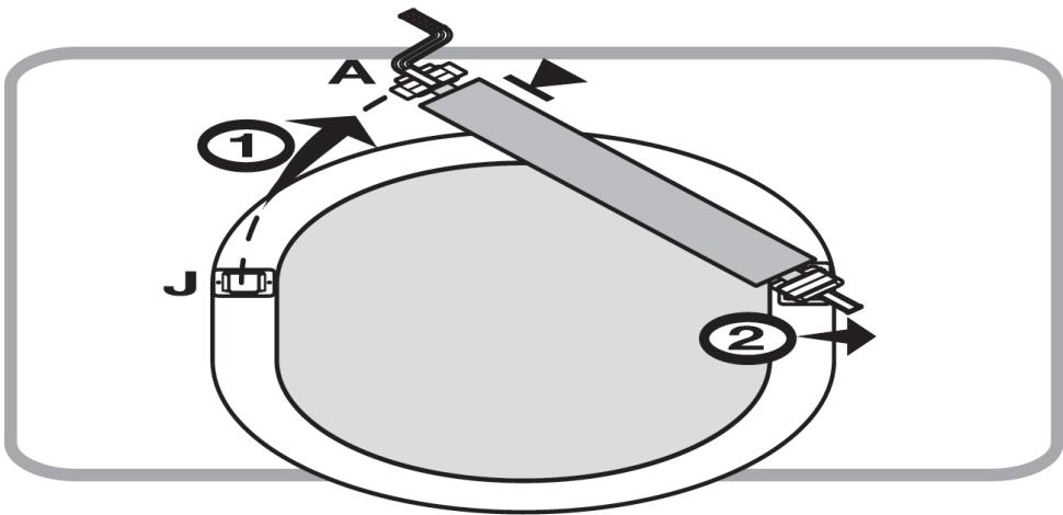
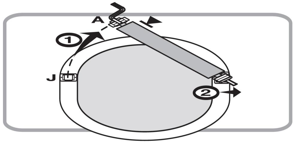
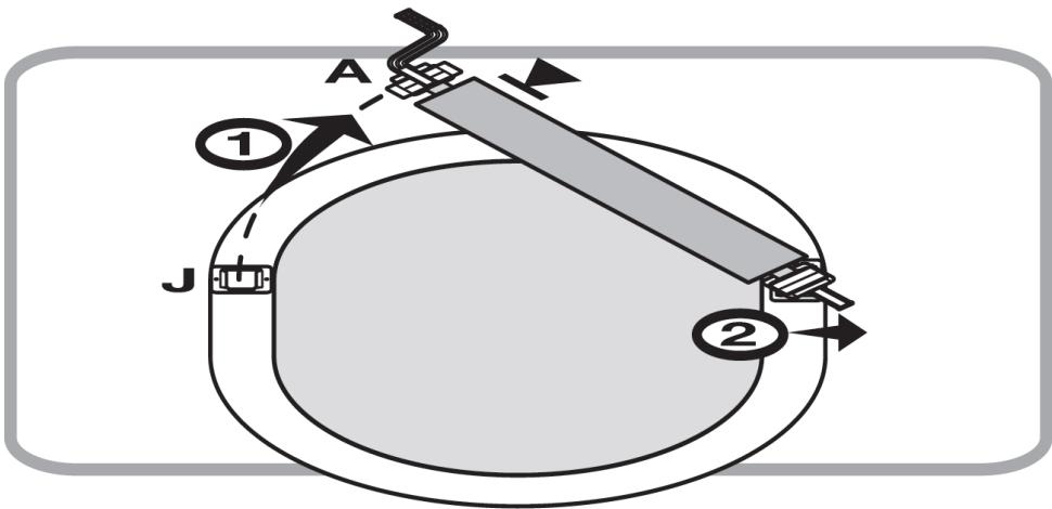
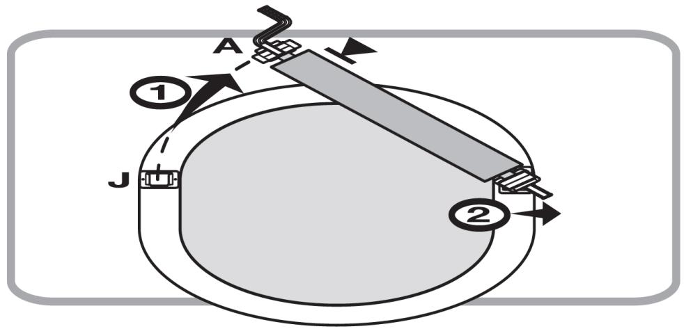
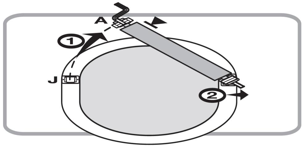
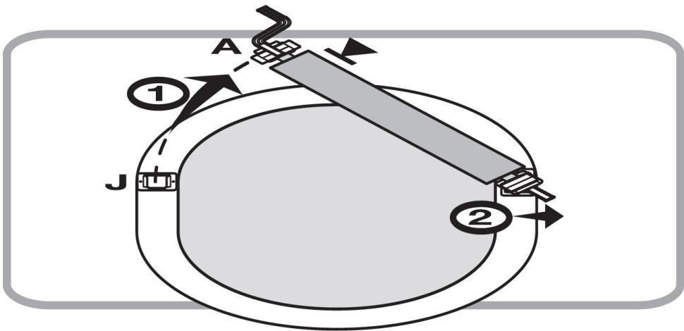
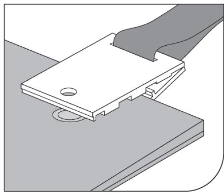
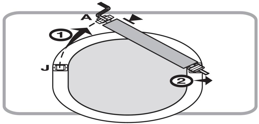
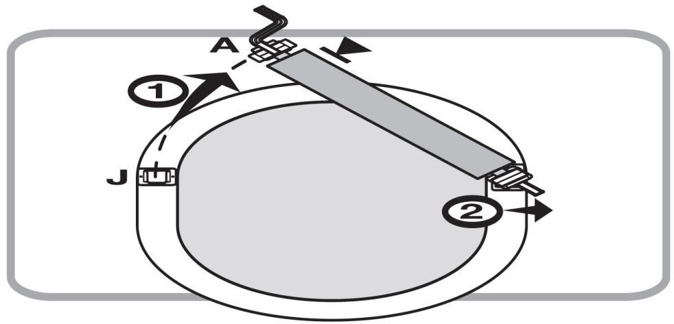
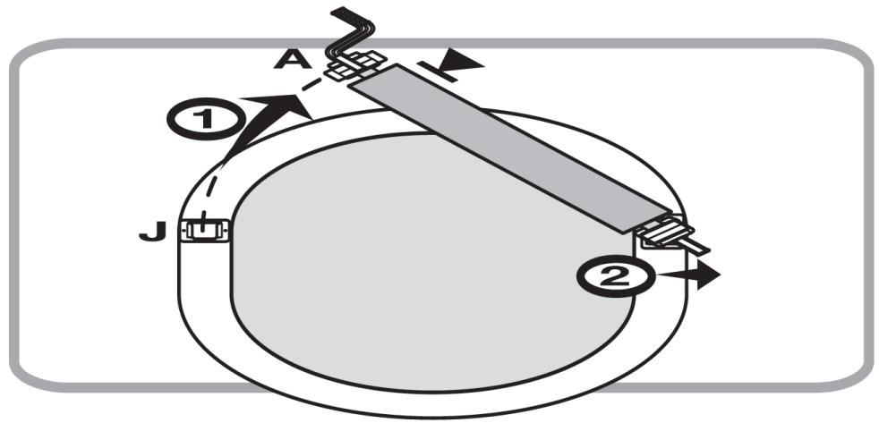
  1. (See fig. 36) To disassemble the product from the pool, pull the support (A) from the base (J) and turn the product against the axle of the second support. Make sure that the support is based on the edge or disassemble the product completely.

3.3. Cleaning and maintenance

a) Use cleaners without corrosive substances to clean each surface.
b) After cleaning the device, all parts should be dried before reusing it.
c) Store the unit in a dry, cool place, free from moisture and direct exposure to sunlight.
d) Never spray the device with water jets.
e) Regular inspections of the device must be carried out in terms of its technical efficiency and any damages.
f) Use a soft cloth for cleaning.

Fig. 1.
Exploded view diagram of a mechanical assembly with numbered parts and corresponding assembly instructions below.

Fig. 2.
Technical diagram showing exploded view of mechanical components with numbered parts and exploded views

A B A B A

Fig. 3
A×1 B×1 Cx1 D×1 L×6 M×2 J×2 K×2 Nx4 Rx3 O×18 Ex8 Fx8 Q×4 Px1 H×8 G×8

Fig. 4.
#13 X2

#13 X2

Fig. 5.
Mechanical diagram showing two circular components with internal structure, connected by a dashed line and labeled 'a' (no text or symbols on the diagrams themselves)

#9-4 b

#9-5 x4 #9-6 x4 C

#9-3 #9-1 #9-2 #9-3 d

Fig. 6.
#2 # #8 # # # # # # # # # # # # # # # # # # # # # # # # # # # # # # # # # # # # # # # # # # # # # # # # # # # # # # # # #5 # # # # # # # # # # # # # # # # # # # # #17 #5

Fig. 7.
graph TD A["#1"] --> B["Engine"] B --> C["Engine 8"] C --> D["Engine 6"] D --> E["Engine 7"] E --> F["Engine 3"] F --> G["Engine 17"] G --> H["Engine 7"] style A fill:#f9f,stroke:#333 style B fill:#ccf,stroke:#333 style C fill:#cfc,stroke:#333 style D fill:#fcc,stroke:#333 style E fill:#cff,stroke:#…

#21

Fig. 8.
#16 #11 #20 #15 #10

Fig. 9.
Uniprodo UNI_POOL_REEL_585 - Cleaning and maintenance - 15

Fig. 10.
#14 30 cm #14 #14

#14 30 cm #14 #14

Fig. 11
Diagram showing two panels with curved arrows indicating rotation or movement (no text or symbols)

30cm 30cm X

Fig. 12.
Diagram of a mechanical assembly with directional arrows indicating motion or flow (no text or symbols present)

Fig. 13.
Pure electrical circuit lines without any symbols

Technical illustration of a mechanical clamp or bracket assembly (no text or symbols visible)

Fig. 14.
Diagram of a mechanical device with a central component and multiple arms, no visible text or symbols

Technical line drawing of a mechanical clamp or bracket assembly (no text or symbols)

Fig. 15.
#7 X2

#7 X2

Fig. 16.
Technical diagram illustrating gear assembly with numbered components and directional arrows, including a zoomed-in view of the final gear assembly.

Fig. 17.

#5

Fig. 18.
#10 #3

#4 #9

Fig. 19
Z= MIN 45 cm Y= MIN 30 cm Z Y Y Z X

Z= MIN 45 cm Y= MIN 30 cm MAX 90 cm Z Y Y Z X

Fig. 20.
Diagram showing airflow or heat transfer between two panels, with arrows indicating direction (no text or symbols)

30cm 30cm X

Fig. 21.
Diagram of a mechanical component with directional arrows indicating motion or flow (no text or symbols)

Fig. 22.
Pure schematic diagram of a mechanical device with no text, numbers, or symbols

Diagram of a mechanical clamp or bracket assembly with a handle, no text or symbols present

Fig. 23.
Pure diagram of a mechanical or electrical component with no text, numbers, or symbols

Mechanical assembly diagram showing a clip attached to a cable with a spring (no text or symbols)

Fig. 24.
Technical diagram showing three different types of spray gun components labeled A, B, and C, with component D indicated.

Fig. 25.
Technical diagram showing two types of hair feeders (A and B) with labeled parts and screw installation details.

Fig. 26.

Technical diagram showing exploded and assembled views of electrical switchgear components with labeled parts A, B, and J.

Fig. 27
| Dimension | Value | |---|---| | 1xP+1xR+1xQ | 137-202cm(54-79.5in) | | 1xR+2xQ | 210-275cm(82-108in) | | 1xP+2xR+2xQ | 242-372cm(95-146in) | | 2xR+3xQ | 315-445cm(124-175in) | | 3xR+4xQ | 420-615cm(165-242in) |

Fig. 28.
P/Q R R P/Q O O O O O O P/Q R

Fig. 29.
M P/Q A M M P/Q B

Fig. 30
L/N A J L B L/N N J

Fig. 31.
Technical diagram illustrating mechanical assembly with labeled components A and B, showing directional arrows and component movement.

Fig. 32.
H E G

Fig. 33
E F 15cm(6in) 15cm(6in) Y

Fig. 34.
Technical diagram showing a mechanical device with a spring and a base plate, no text or symbols present

Fig. 35.
Technical diagram of a mechanical device with labeled components (E and H), showing internal structure and wiring (no text or symbols beyond labels)

Fig. 36.
A ① J ②

Uniprodo UNI_POOL_REEL_585 - Cleaning and maintenance - 53

3.2.2. UNI_POOL_REEL_570

3.2.3. UNI_POOL_REEL_585

Rys. 2.
Technical diagram showing exploded view of mechanical components with numbered parts and exploded views

A B A B A

Rys. 3
A×1 B×1 Cx1 D×1 L×6 M×2 J×2 K×2 Nx4 Rx3 O×18 Ex8 Fx8 Q×4 Px1 H×8 G×8

Rys. 4.
#13 X2

#13 X2

Rys. 5.
Diagram of two circular mechanical components with directional arrows, no text or symbols present

#9-4 b

#9-5 x4 #9-6 x4 C

#9-3 #9-1 #9-2 #9-3 d

Rys. 6.
graph TD A["Step #2"] --> B["Assembly #8"] B --> C["Step #4"] C --> D["Assembly #5"] D --> E["Step #17"] E --> F["Assembly #5"] style A fill:#f9f,stroke:#333 style B fill:#ccf,stroke:#333 style C fill:#cfc,stroke:#333 style D fill:#fcc,stroke:#333 style E fill:#cff,stroke:#333 style F fill:#ffc,stro…

Rys. 7.
graph TD A["#1"] --> B["Engine"] B --> C["Engine 8"] C --> D["Engine 6"] D --> E["Engine 7"] E --> F["Engine 3"] F --> G["Engine 17"] G --> H["Engine 7"] style A fill:#f9f,stroke:#333 style B fill:#ccf,stroke:#333 style C fill:#cfc,stroke:#333 style D fill:#fcc,stroke:#333 style E fill:#cff,stroke:#…

#21

Rys. 8.
#16 #11 #20 #15 #10

Rys. 9.
Uniprodo UNI_POOL_REEL_585 - UNI_POOL_REEL_585 - 14

Rys. 10.
#14 30 cm #14 #14

#14 30 cm #14 #14

rys. 11
Diagram showing two panels with curved arrows indicating rotation or movement (no text or symbols)

30cm 30cm X

Rys. 12.
Diagram of a mechanical assembly with directional arrows indicating flow or movement (no text or symbols present)

Rys. 13.
Pure electrical circuit lines without any symbols

Technical illustration of a mechanical clamp or bracket assembly (no text or symbols visible)

Rys. 14.
Pure mechanical diagram of a cylindrical device with attached clamps and a base, without any text, numbers, or symbols.

Technical illustration of a mechanical clamp or bracket assembly (no text or symbols visible)

Rys. 15.

#7 X2

#7 X2

Rys. 16.

Technical diagram illustrating gear assembly with numbered components and directional arrows, including a close-up of the final gear assembly.

Ryc. 17.

#5

Rys. 18.
#10 #3

#4 #9

rys. 19
Z= MIN 45 cm Y= MIN 30 cm Z Y Y Z X

Z= MIN 45 cm Y= MIN 30 cm MAX 90 cm Z Y Y Z X

Ryc. 20.
Diagram showing airflow or heat transfer between two panels, with arrows indicating direction (no text or symbols)

30cm 30cm X

Ryc. 21.
Diagram of a mechanical component with directional arrows indicating motion or flow (no text or symbols)

Ryc. 22.
Pure schematic diagram of a mechanical device with no text, numbers, or symbols

Technical illustration of a mechanical clamp or bracket assembly (no text or symbols visible)

Ryc. 23.
Diagram of a mechanical device with a central component and two vertical supports, enclosed in a rectangular frame (no text or symbols)

Technical illustration of a mechanical clamp or bracket assembly (no text or symbols visible)

Ryc. 24.
Technical diagram showing three different types of spray gun components labeled A, B, and C, with component D indicated.

Ryc. 25.
Technical diagram showing two types of hair feeders (A and B) with labeled parts and screw installation details.

Ryc. 26.

Technical diagram showing exploded and assembled views of electrical switchgear components with labeled parts A, B, and J.

rys. 27

| Dimension | Value | |---|---| | 1xP+1xR+1xQ | 137-202cm(54-79.5in) | | 1xR+2xQ | 210-275cm(82-108in) | | 1xP+2xR+2xQ | 242-372cm(95-146in) | | 2xR+3xQ | 315-445cm(124-175in) | | 3xR+4xQ | 420-615cm(165-242in) |

Ryc. 28.

P/Q R R P/Q O O O O O O P/Q R

Ryc. 29.

M P/Q A M P/Q B

rys. 30

L/N A J L B L/N N J

Ryc. 31.

Technical diagram illustrating mechanical assembly with labeled components A and B, showing directional arrows and component movement.

Ryc. 32.

H E G

rys. 33

E F 15cm(6in) 15cm(6in) Y

Ryc. 34.

Technical diagram of a mechanical device with two views: one showing a spring-loaded mechanism and the other showing a flat plate with labeled parts H and E (no text or symbols beyond labels)

Ryc. 35.
Technical diagram of a mechanical assembly with labeled parts E and H, showing internal components and connections (no text or symbols beyond labels)

Ryc. 36.
A ① J ②

Uniprodo UNI_POOL_REEL_585 - UNI_POOL_REEL_585 - 52

3.2.2. UNI_POOL_REEL_570

3.2.3. UNI_POOL_REEL_585

Obr. 2
Technical diagram showing exploded view of mechanical components with numbered parts and exploded views

A B A B A

Obr

A×1 B×1 C×1 D×1 L×6 M×2 J×2 K×2 Nx4 Rx3 O×18 Ex8 Fx8 Q×4 Px1 H×8 G×8

Obr.

#13 X2

#13 X2

Obr.

Diagram of two circular mechanical components with directional arrows, no text or symbols present

#9-4 b

#9-5 x4 #9-6 x4 C

#9-3 #9-1 #9-2 #9-3 d

Obr.

graph TD A["Step #2"] --> B["Assembly #8"] B --> C["Step #4"] C --> D["Assembly #5"] D --> E["Step #17"] E --> F["Assembly #5"] style A fill:#f9f,stroke:#333 style B fill:#ccf,stroke:#333 style C fill:#cfc,stroke:#333 style D fill:#fcc,stroke:#333 style E fill:#cff,stroke:#333 style F fill:#ffc,stro…

Obr. 7

Diagram illustrating the assembly of a mechanical component with numbered parts and directional arrows indicating motion or assembly.

#21

Obr. 8

#16 #11

#10 #20 #15

Obr. 9

Z= MIN 45 cm Y= MIN 30 cm Y Y Z Z X

Z= MIN 45 cm Y= MIN 30 cm MAX 90 cm Z Y Y Z X

Obr. 10

#14 30 cm #14 #14

#14 30 cm #14 #14

obr. 11

Diagram showing two panels with curved arrows indicating rotation or movement (no text or symbols)

30cm 30cm X

Obr. 12

Diagram of a mechanical assembly with directional arrows indicating motion or flow (no text or symbols present)

Obr. 13.

Pure electrical circuit lines without any symbols

Illustration of a mechanical clamp or bracket assembly with a handle and mounting base (no text or symbols)

Obr. 14.

Pure mechanical diagram of a cylindrical device with attached clamps and a central housing (no text or symbols)

Technical line drawing of a mechanical clamp or bracket assembly (no text or symbols)

Obr. 15.

#7 X2

#7 X2

Obr. 16.

Technical diagram illustrating gear assembly with numbered components and directional arrows, including a close-up of the final gear assembly.

Obr. 17.

#5

Obr.

#10 #3

#4 #9

obr. 19

Z=MIN 45 cm Y=MIN 30 cm
Y Z Y Z X

Z=MIN 45 cm Y=MIN 30 cm
Z Y Y Z MAX 90 cm X

Obr. 20

Diagram showing airflow or heat transfer between two panels, one with curved arrows indicating direction (no text or symbols)

30cm 30cm X

Obr.

Diagram of a mechanical component with directional arrows indicating motion or flow (no text or symbols)

Obr. 22

Pure schematic diagram of a mechanical device with no text, numbers, or symbols

Technical illustration of a mechanical clamp or bracket assembly (no text or symbols visible)

Obr.

Diagram of a mechanical device with a central component and two vertical supports, enclosed in a rectangular frame (no text or symbols)

Technical illustration of a mechanical clamp or bracket assembly (no text or symbols visible)

Obr. 24

Technical diagram showing three different types of spray machines labeled A, B, and C, with D indicating a specific component.

Obr.

Technical diagram showing two types of hair tools labeled A and B, with screw being inserted into a spring (A) and then being inserted into a screw (B), with arrows indicating the process.

Obr. 26.

Technical diagram showing assembly of mechanical components with labeled parts A, B, and J, including a schematic view of a device with x-axis.

obr. 27

| Dimension | Value | |---|---| | 1xP+1xR+1xQ | 137-202cm(54-79.5in) | | 1xR+2xQ | 210-275cm(82-108in) | | 1xP+2xR+2xQ | 242-372cm(95-146in) | | 2xR+3xQ | 315-445cm(124-175in) | | 3xR+4xQ | 420-615cm(165-242in) |

Obr. 28.

P/Q R R P/Q O O O O O O P/Q R

Obr. 29.

M P/Q A M P/Q B

obr. 30

L/N A J L N B L/N J

Obr. 31.

Technical diagram illustrating mechanical assembly with labeled components A and B, showing directional arrows and component movement.

Obr. 32.

H E G

obr. 33

E F 15cm(6in) 15cm(6in) Y

Obr. 34.

Technical diagram of a mechanical device with two views: one showing a spring-loaded mechanism and the other showing a flat plate with labeled parts H and E (no text or symbols beyond labels)

Obr. 35.

Technical diagram of a mechanical assembly with labeled parts E and H, showing internal components and connections (no text or symbols beyond labels)

Obr. 36.

A ① J ②

Uniprodo UNI_POOL_REEL_585 - UNI_POOL_REEL_585 - 54

3.2.2. UNI_POOL_REEL_570

3.2.3. UNI_POOL_REEL_585

Fig. 2.
Technical diagram showing exploded view of mechanical components with numbered parts and exploded views

A B A B A

Fig. 3
A×1 B×1 Cx1 D×1 L×6 M×2 J×2 K×2 Nx4 Rx3 O×18 Ex8 Fx8 Q×4 Px1 H×8 G×8

Fig. 4.
#13 X2

#13 X2

Fig. 5.
Diagram of two circular mechanical components with directional arrows, no text or symbols present

#9-4 b

#9-5 x4 #9-6 x4 C

#9-3 #9-1 #9-2 #9-3 d

Fig. 6.
graph TD A["Step #2"] --> B["Assembly #8"] B --> C["Step #4"] C --> D["Assembly #5"] D --> E["Step #17"] E --> F["Assembly #5"] style A fill:#f9f,stroke:#333 style B fill:#ccf,stroke:#333 style C fill:#cfc,stroke:#333 style D fill:#fcc,stroke:#333 style E fill:#cff,stroke:#333 style F fill:#ffc,stro…

Fig. 7.
graph TD A["#1"] --> B["Engine"] B --> C["Engine 8"] C --> D["Engine 6"] D --> E["Engine 7"] E --> F["Engine 3"] F --> G["Engine 17"] G --> H["Engine 7"] style A fill:#f9f,stroke:#333 style B fill:#ccf,stroke:#333 style C fill:#cfc,stroke:#333 style D fill:#fcc,stroke:#333 style E fill:#cff,stroke:#…

#21

Fig. 8.
#16 #11 #20 #15 #10

Fig. 9.
Uniprodo UNI_POOL_REEL_585 - UNI_POOL_REEL_585 - 14

Fig. 10.
#14 30 cm #14 #14

#14 30 cm #14 #14

fig. 11
Diagram showing two panels with curved arrows indicating rotation or movement (no text or symbols)

30cm 30cm X

Fig. 12.
Diagram of a mechanical assembly with directional arrows indicating flow or movement (no text or symbols present)

Fig. 13.
Pure electrical circuit lines without any symbols

Technical illustration of a mechanical clamp or bracket assembly (no text or symbols visible)

Fig. 14.
Pure mechanical diagram of a cylindrical device with attached clamps and a central housing (no text or symbols)

Technical line drawing of a mechanical clamp or bracket assembly (no text or symbols)

Fig. 15.
#7 X2

#7 X2

Fig. 16.
Technical diagram illustrating gear assembly with numbered components and directional arrows, including a close-up of the final gear assembly.

Fig. 17.

#5

Fig. 18.
#10 #3

#4 #9

fig. 19
Z= MIN 45 cm Y= MIN 30 cm Z Y Y Z X

Z= MIN 45 cm Y= MIN 30 cm MAX 90 cm Z Y Y Z X

Fig. 20.
Diagram showing airflow or heat transfer between two panels, with arrows indicating direction (no text or symbols)

30cm 30cm X

Fig. 21.
Diagram of a mechanical component with directional arrows indicating motion or flow (no text or symbols)

Fig. 22.
Pure schematic diagram of a mechanical device with no text, numbers, or symbols

Diagram of a mechanical clamp or bracket assembly with a handle, no text or symbols present

Fig. 23.
Pure diagram of a mechanical or electrical component with no text, numbers, or symbols

Technical illustration of a mechanical clamp or bracket assembly (no text or symbols visible)

Fig. 24.
Technical diagram showing three different types of spray gun components labeled A, B, and C, with component D indicated.

Fig. 25.
Technical diagram showing two types of hair feeders (A and B) with labeled parts and screw installation details.

Fig. 26.

Technical diagram showing exploded and assembled views of electrical switchgear components with labeled parts A, B, and J.

fig. 27
| Dimension | Value | | :--- | :--- | | 1xP+1xR+1xQ | 137-202cm(54-79.5in) | | 1xR+2xQ | 210-275cm(82-108in) | | 1xP+2xR+2xQ | 242-372cm(95-146in) | | 2xR+3xQ | 315-445cm(124-175in) | | 3xR+4xQ | 420-615cm(165-242in) |

Fig. 28.

P/Q R R P/Q O O O O O O P/Q R

Fig. 29.
M P/Q A M P/Q B

fig. 30
L/N A J L N B L/N J

Fig. 31.
Technical diagram illustrating mechanical assembly with labeled components A and B, showing directional arrows and component movement.

Fig. 32.
H E G

fig. 33
E F 15cm(6in) 15cm(6in) Y

Fig. 34.
Technical diagram of a mechanical device with two views: top shows a cylindrical component with attached pins, bottom shows a flat plate with labeled parts H and E (no text or symbols beyond labels)

Fig. 35.
Technical diagram of a mechanical device with labeled components (E and H), showing internal components and wiring (no text or symbols beyond labels)

Fig. 36.
A ① J ②

Uniprodo UNI_POOL_REEL_585 - UNI_POOL_REEL_585 - 52

3.2.2. UNI_POOL_REEL_570

3.2.3. UNI_POOL_REEL_585

A B A B A

#9-1 x1 #9-2 x1 #9-3 x1 #9-4 x2 #9-5 x4 #9-6 x4

Figura 2.
Technical diagram showing exploded view of mechanical components with numbered parts and exploded views

A B A B A

Figura 3
A×1 B×1 Cx1 D×1 L×6 M×2 J×2 K×2 Nx4 Rx3 O×18 Ex8 Fx8 Q×4 Px1 H×8 G×8

Figura 4.
#13 X2

#13 X2

Figura 5.
Diagram of two circular mechanical components with directional arrows, no text or symbols present

#9-4 b

#9-5 x4 #9-6 x4 C

#9-3 #9-1 #9-2 #9-3 d

Figura 6.
#2 # #8 # # # # # # # # # # # # # # # # # # # # # # # # # # # # # # # # # # # # # # # # # # # # # # # # # # # # # # # # #5 # # # # # # # # # # # # # # # # # # # # #17 #5

Figura 7.
graph TD A["#1"] --> B["Engine"] B --> C["Engine Block #8"] C --> D["Engine Block #6"] D --> E["Engine Block #7"] E --> F["Engine Block #3"] F --> G["Engine Block #17"] G --> H["Engine Block #7"] style A fill:#f9f,stroke:#333 style B fill:#ccf,stroke:#333 style C fill:#cfc,stroke:#333 style D fill:#…

#21

Figura 8.
#16 #11

#10 #20 #15

Figura 9.
Uniprodo UNI_POOL_REEL_585 - UNI_POOL_REEL_585 - 17

Figura 10.
#14 30 cm #14 #14

#14 30 cm #14 #14

fig. 11
Diagram showing two panels with curved arrows indicating rotation or movement (no text or symbols)

30cm 30cm X

Figura 12.
Diagram of a mechanical assembly with directional arrows indicating motion or flow (no text or symbols)

Figura 13.
Pure electrical circuit lines without any symbols

Technical illustration of a mechanical clamp or bracket assembly (no text or symbols visible)

Figura 14.
Diagram of a mechanical device with a central housing and multiple arms, no visible text or symbols

Technical line drawing of a mechanical clamp or bracket assembly (no text or symbols)

Figura 15.
#7 X2

#7 X2

Figura 16.
Technical diagram illustrating gear assembly with numbered components and directional arrows, including a zoomed-in view of the final gear assembly.

Figura 17.

#5

Figura 18.
#10 #3

#4 #9

fig. 19
Z= MIN 45 cm Y= MIN 30 cm Z Y Y Z X

Z= MIN 45 cm Y= MIN 30 cm MAX 90 cm Z Y Y Z X

Figura 20.
Diagram showing airflow or heat transfer between two panels, with arrows indicating direction (no text or symbols)

30cm 30cm X

Figura 21.
Diagram of a mechanical component with directional arrows indicating motion or flow (no text or symbols)

Figura 22.
Pure schematic diagram of a mechanical device with no text, numbers, or symbols

Technical illustration of a mechanical clamp or bracket assembly (no text or symbols visible)

Figura 23.
Diagram of a mechanical device with a central component and two vertical supports, enclosed in a rectangular frame (no text or symbols)

Technical illustration of a mechanical clamp or bracket assembly (no text or symbols visible)

Figura 24.
Technical diagram showing three different types of spray gun components labeled A, B, and C, with component D indicated.

Figura 25.
Technical diagram showing two types of hair feeders (A and B) with labeled parts and screw installation details.

Figura 26.

Technical diagram showing exploded and assembled views of electrical switchgear components with labeled parts A, B, and J.

fig. 27
| Dimension | Value | |---|---| | 1xP+1xR+1xQ | 137-202cm(54-79.5in) | | 1xR+2xQ | 210-275cm(82-108in) | | 1xP+2xR+2xQ | 242-372cm(95-146in) | | 2xR+3xQ | 315-445cm(124-175in) | | 3xR+4xQ | 420-615cm(165-242in) |

Figura 28.
P/Q R R P/Q O O O O O O P/Q R

Figura 29.
M P/Q A M M P/Q B

fig. 30
L/N A J L N B L/N J

Figura 31.
Technical diagram illustrating mechanical assembly with labeled components A and B, showing directional arrows and component movement.

Figura 32.
H E G

fig. 33
E F 15cm(6in) 15cm(6in) Y

Figura 34.
Technical diagram of a mechanical device with two views: one showing a spring-loaded mechanism and the other showing a flat plate with labeled parts H and E (no text or symbols beyond labels)

Figura 35.
Technical diagram of a mechanical assembly with labeled parts E and H, showing internal components and connections (no text or symbols beyond labels)

Figura 36.
A ① J ②

Uniprodo UNI_POOL_REEL_585 - UNI_POOL_REEL_585 - 55

3.2.2. UNI_POOL_REEL_570

3.2.3. UNI_POOL_REEL_585

Figura 2.
Technical diagram showing exploded view of mechanical components with numbered parts and exploded views

A B A B A

Figura 3
A×1 B×1 Cx1 D×1 L×6 M×2 J×2 K×2 Nx4 Rx3 O×18 Ex8 Fx8 Q×4 Px1 H×8 G×8

Figura 4.
#13 X2

#13 X2

Figura 5.
Diagram of two circular mechanical components with directional arrows, no text or symbols present

#9-4 b

#9-5 x4 #9-6 x4 C

#9-3 #9-1 #9-2 #9-3 d

Figura 6.
#2 # #8 # # # # # # # # # # # # # # # # # # # # # # # # # # # # # # # # # # # # # # # # # # # # # # # # # # # # # # # # # #5 # # # # # # # # # # # # # # # # # # # # # #17 #5

Figura 7.
graph TD A["Component #1"] --> B["Part with roller"] B --> C["Component #8"] C --> D["Part with roller"] D --> E["Component #6"] E --> F["Part with roller"] F --> G["Component #7"] G --> H["Part with wheel"] H --> I["Component #3"] I --> J["Part with wheel"] J --> K["Component #17"] K --> L["Part wi…

#21

Figura 8.
#16 #11 #20 #15 #10

Figura 9.
Uniprodo UNI_POOL_REEL_585 - UNI_POOL_REEL_585 - 14

Figura 10.
#14 30 cm #14 #14

#14 30 cm #14 #14

Figura 11
Diagram showing two panels with curved arrows indicating rotation or movement (no text or symbols)

30cm 30cm X

Figura 12.
Diagram of a mechanical assembly with directional arrows indicating motion or flow (no text or symbols present)

Figura 13.
Pure electrical circuit lines without any symbols

Technical illustration of a mechanical clamp or bracket assembly (no text or symbols visible)

Figura 14.
Diagram of a mechanical device with a central component and multiple arms, no visible text or symbols

Technical line drawing of a mechanical clamp or bracket assembly (no text or symbols)

Figura 15.
#7 X2

#7 X2

Figura 16.
Technical diagram illustrating gear assembly with labeled components and directional arrows, including parts #12 and #13.

Figura 17.

#5 0

Figura 18.
#10 #3

#4 #9

Figura 19
Z= MIN 45 cm Y= MIN 30 cm Z Y Y Z X

Z= MIN 45 cm Y= MIN 30 cm MAX 90 cm Z Y Y Z X

Figura 20.
Diagram showing airflow or heat transfer between two panels, with arrows indicating direction (no text or symbols)

30cm 30cm X

Figura 21.
Diagram of a mechanical component with directional arrows indicating motion or flow (no text or symbols)

Figura 22.
Pure schematic diagram of a mechanical device with no text, numbers, or symbols

Technical illustration of a mechanical clamp or bracket assembly (no text or symbols visible)

Figura 23.
Diagram of a mechanical device with a central component and two vertical supports, enclosed in a rectangular frame (no text or symbols)

Technical illustration of a mechanical clamp or bracket assembly (no text or symbols visible)

Figura 24.
Technical diagram showing three different types of spray gun components labeled A, B, and C, with component D indicated.

Figura 25.
Technical diagram showing two types of hair feeders (A and B) with labeled parts and screw installation details.

Figura 26.

Technical diagram showing exploded and assembled views of electrical switchgear components with labeled parts A, B, and J.

Figura 27
| Dimension | Value | |---|---| | 1xP+1xR+1xQ | 137-202cm(54-79.5in) | | 1xR+2xQ | 210-275cm(82-108in) | | 1xP+2xR+2xQ | 242-372cm(95-146in) | | 2xR+3xQ | 315-445cm(124-175in) | | 3xR+4xQ | 420-615cm(165-242in) |

Figura 28.
P/Q R R P/Q O O O O O O P/Q R

Figura 29.
M P/Q A M M P/Q B

Figura 30
L/N A J L N B L/N J

Figura 31.
Technical diagram illustrating mechanical assembly with labeled components A and B, showing directional arrows and component movement.

Figura 32.
H E G

Figura 33
E F 15cm(6in) 15cm(6in) Y

Figura 34.
Technical diagram of a mechanical device with two views: one showing a spring-loaded mechanism and the other showing a flat plate with labeled parts H and E (no text or symbols beyond labels)

Figura 35.
Technical diagram of a mechanical assembly with labeled parts E and H, showing internal components and connections (no text or symbols beyond labels)

Figura 36.
A ① J ②

Uniprodo UNI_POOL_REEL_585 - UNI_POOL_REEL_585 - 52

3.2.2. UNI_POOL_REEL_570

3.2.3. UNI_POOL_REEL_585

A B A B A

#9-1 x1 #9-2 x1 #9-3 x1 #9-4 x2 #9-5 x4 #9-6 x4

  1. ábra.

Technical diagram showing exploded view of mechanical components with numbered parts and exploded views

A B A B A

  1. ábra

A×1 B×1 C×1 D×1 L×6 M×2 J×2 K×2 Nx4 Rx3 O×18 Ex8 Fx8 Q×4 Px1 H×8 G×8

  1. ábra.

#13 X2

#13 X2

  1. ábra.

Diagram of two circular mechanical components with directional arrows, no text or symbols present

#9-4 b

#9-5 x4 #9-6 x4 C

#9-3 #9-1 #9-2 #9-3 d

  1. ábra.

#2 # #8 # # # # # # # # # # # # # # # # # # # # # # # # # # # # # # # # # # # # # # # # # # # # # # # # # # # # # # # # # #5 # # # # # # # # # # # # # # # # # # # #17 #5

  1. ábra.

Diagram illustrating the assembly of a mechanical component with numbered parts and directional arrows indicating motion or assembly.

#21

  1. ábra.

#16 #11

#10 #20 #15

  1. ábra.

Z= MIN 45 cm Y= MIN 30 cm Y Y Z Z X

Z= MIN 45 cm Y= MIN 30 cm MAX 90 cm Z Y Y Z X

  1. ábra.

#14 30 cm #14 #14

#14 30 cm #14 #14

  1. ábra

Diagram showing two panels with curved arrows indicating rotation or flow, no text or symbols present

30cm 30cm X

  1. ábra.

Diagram of a mechanical assembly with directional arrows indicating motion or flow (no text or symbols)

  1. ábra.

Pure electrical circuit lines without any symbols

Technical illustration of a mechanical clamp or bracket assembly (no text or symbols visible)

  1. ábra.

Diagram of a mechanical device with a central component and multiple arms, no visible text or symbols

Technical line drawing of a mechanical clamp or bracket assembly (no text or symbols)

  1. ábra.

#7 X2

#7 X2

  1. ábra.

Technical diagram illustrating gear assembly with labeled components and directional arrows, including parts #12 and #13.

  1. ábra.

#5 0

  1. ábra.

#10 #3

#4 #9

  1. ábra

Z= MIN 45 cm Y= MIN 30 cm Z Y Y Z X

Z= MIN 45 cm Y= MIN 30 cm MAX 90 cm Z Y Y Z X

  1. ábra.

Diagram showing airflow or heat transfer between two panels, with arrows indicating direction (no text or symbols)

30cm 30cm X

  1. ábra.

Diagram of a mechanical component with directional arrows indicating motion or flow (no text or symbols)

  1. ábra.

Pure schematic diagram of a mechanical device with no text, numbers, or symbols

Diagram of a mechanical clamp or bracket assembly with a handle and mounting base (no text or symbols)

  1. ábra.

Diagram of a mechanical device with a central component and two vertical supports, enclosed in a rectangular frame (no text or symbols)

Technical illustration of a mechanical clamp or bracket assembly (no text or symbols visible)

  1. ábra.

Technical diagram showing three different types of spray gun components labeled A, B, and C, with component D indicated.

  1. ábra.

Technical diagram showing two types of hair feeders (A and B) with labeled parts and screw installation details.

  1. ábra.

Technical diagram showing exploded and assembled views of electrical switchgear components with labeled parts A, B, and J.

  1. ábra
    Uniprodo UNI_POOL_REEL_585 - UNI_POOL_REEL_585 - 46
  1. ábra.
    Uniprodo UNI_POOL_REEL_585 - UNI_POOL_REEL_585 - 47
  1. ábra.
    Uniprodo UNI_POOL_REEL_585 - UNI_POOL_REEL_585 - 48
  1. ábra

L/N A J L B L/N N J

  1. ábra.

Technical diagram illustrating mechanical assembly with labeled components A and B, showing directional arrows and component movement.

  1. ábra.

H E G

  1. ábra

E F 15cm(6in) 15cm(6in) Y

  1. ábra.

Technical diagram of a mechanical device with two views: one showing a spring-loaded mechanism and the other showing a flat plate with labeled parts H and E (no text or symbols beyond labels)

  1. ábra.

Technical diagram of a mechanical assembly with labeled parts E and H, showing internal components and connections (no text or symbols beyond labels)

  1. ábra.

A ① J ②

Uniprodo UNI_POOL_REEL_585 - UNI_POOL_REEL_585 - 56

3.2.2. UNI_POOL_REEL_570

3.2.3. UNI_POOL_REEL_585

Fig. 2.
Technical diagram showing exploded view of mechanical components with numbered parts and exploded views

A B A B A

Fig. 3
A×1 B×1 Cx1 D×1 L×6 M×2 J×2 K×2 Nx4 Rx3 O×18 Ex8 Fx8 Q×4 Px1 H×8 G×8

Fig. 4.
#13 X2

#13 X2

Fig. 5.
Mechanical diagram showing two circular components with internal structure and directional arrows, no text or symbols present.

#9-4 b

#9-5 x4 #9-6 x4 C

#9-3 #9-1 #9-2 #9-3 d

Fig. 6.
#2 # #8 # # # # # # # # # # # # # # # # # # # # # # # # # # # # # # # # # # # # # # # # # # # # # # # # # # # # # # # # #5 # # # # # # # # # # # # # # # # # # # # #17 #5

Fig. 7.
graph TD A["Component #1"] --> B["Part with roller"] B --> C["Component #8"] C --> D["Part with roller"] D --> E["Component #6"] E --> F["Part with roller"] F --> G["Component #7"] G --> H["Part with wheel"] H --> I["Component #3"] I --> J["Part with wheel"] J --> K["Component #17"] K --> L["Part wi…

#21

Fig. 8.
#16 #11 #20 #15 #10

Fig. 9.
Uniprodo UNI_POOL_REEL_585 - UNI_POOL_REEL_585 - 14

Fig. 10.
#14 30 cm #14 #14

#14 30 cm #14 #14

fig. 11
Diagram showing two panels with curved arrows indicating rotation or movement (no text or symbols)

30cm 30cm X

Fig. 12.
Diagram of a mechanical assembly with directional arrows indicating flow or movement (no text or symbols present)

Fig. 13.
Pure electrical circuit lines without any symbols

Technical illustration of a mechanical clamp or bracket assembly (no text or symbols visible)

Fig. 14.
Pure mechanical diagram of a cylindrical device with attached clamps and a central housing (no text or symbols)

Technical line drawing of a mechanical clamp or bracket assembly (no text or symbols)

Fig. 15.
#7 X2

#7 X2

Fig. 16.
Technical diagram illustrating gear assembly with labeled components and directional arrows, including parts #12 and #13.

Fig. 17.

#5

Fig. 18.
#10 #3

#4 #9

fig. 19
Z= MIN 45 cm Y= MIN 30 cm Z Y Y Z X

Z= MIN 45 cm Y= MIN 30 cm MAX 90 cm Z Y Y Z X

Fig. 20.
Diagram showing airflow or heat transfer between two panels, with arrows indicating direction (no text or symbols)

30cm 30cm X

Fig. 21.
Diagram of a mechanical component with directional arrows indicating motion or flow (no text or symbols)

Fig. 22.
Pure schematic diagram of a mechanical device with no text, numbers, or symbols

Diagram of a mechanical clamp or bracket assembly with a handle, showing no text or symbols

Fig. 23.
Pure diagram of a mechanical or electrical component with no text, numbers, or symbols

Technical illustration of a mechanical clamp or bracket assembly (no text or symbols visible)

Fig. 24.
Technical diagram showing three different types of spray gun components labeled A, B, and C, with component D indicated.

Fig. 25.
Technical diagram showing two types of hair feeders (A and B) with labeled parts and screw installation details.

Fig. 26.

Technical diagram showing exploded and assembled views of electrical switchgear components with labeled parts A, B, and J.

fig. 27
| Dimension | Value | |---|---| | 1xP+1xR+1xQ | 137-202cm(54-79.5in) | | 1xR+2xQ | 210-275cm(82-108in) | | 1xP+2xR+2xQ | 242-372cm(95-146in) | | 2xR+3xQ | 315-445cm(124-175in) | | 3xR+4xQ | 420-615cm(165-242in) |

Fig. 28.

P/Q R R P/Q O O O O O O P/Q R

Fig. 29.
M P/Q A M M P/Q B

fig. 30
L/N A J L N B L/N J

Fig. 31.
Technical diagram illustrating mechanical assembly with labeled components A and B, showing directional arrows and component movement.

Fig. 32.
H E G

fig. 33
E F 15cm(6in) 15cm(6in) Y

Fig. 34.
Technical diagram showing a mechanical device with spring and base plate, alongside its schematic view (no text or symbols)

Fig. 35.
Technical diagram of a mechanical device with labeled components (E and H), showing internal structure and wiring (no text or symbols beyond labels)

Fig. 36.
A ① J ②

Uniprodo UNI_POOL_REEL_585 - UNI_POOL_REEL_585 - 52

3.2.2. UNI_POOL_REEL_570

3.2.3. UNI_POOL_REEL_585

Kuva 2.

Technical diagram showing exploded view of mechanical components with numbered parts and exploded views

A B A B A

Kuva 3
A×1 B×1 C×1 D×1 L×6 M×2 J×2 K×2 Nx4 Rx3 O×18 Ex8 Fx8 Q×4 Px1 H×8 G×8

Kuva 4.
#13 X2

#13 X2

Kuva 5.

Diagram of two circular mechanical components with directional arrows, no text or symbols present

#9-4 b

#9-5 x4 #9-6 x4 C

#9-3 #9-1 #9-2 #9-3 d

Kuva 6.

graph TD A["Step 2: #2"] --> B["Step 3: #8"] B --> C["Step 4: #4"] C --> D["Step 5: #5"] D --> E["Step 17: #17"] style A fill:#f9f,stroke:#333 style E fill:#bbf,stroke:#333

Kuva 7.

Diagram illustrating the assembly of a mechanical component with numbered parts and directional arrows indicating motion or assembly.

#21

Kuva 8.

#16 #11

#10 #20 #15

Kuva 9.

Z= MIN 45 cm Y= MIN 30 cm Z Y Y Z X

Z= MIN 45 cm Y= MIN 30 cm MAX 90 cm Z Y Y Z X

Kuva 10.

#14 30 cm #14 #14

#14 30 cm #14 #14

Kuva 11

Diagram showing two panels with curved arrows indicating rotation or movement (no text or symbols)

30cm 30cm X

Kuva 12.

Diagram of a mechanical assembly with directional arrows indicating motion or flow (no text or symbols present)

Kuva 13.

Pure electrical circuit lines without any symbols

Technical illustration of a mechanical clamp or bracket assembly (no text or symbols visible)

Kuva 14.

Diagram of a mechanical device with a central component and multiple arms, no visible text or symbols

Technical line drawing of a mechanical clamp or bracket assembly (no text or symbols)

Kuva 15.

#7 X2

#7 X2

Kuva 16.

Technical diagram illustrating gear assembly with labeled components and directional arrows, including parts #12 and #13.

Kuva 17.

#5

Kuva 18.

#10 #3

#4 #9

Kuva 19

Z=MIN 45 cm Y=MIN 30 cm
Y Z Y Z X

Z=MIN 45 cm Y=MIN 30 cm
MAX 90 cm Z Y Y Z X

Kuva 20.

Diagram showing airflow or heat transfer between two panels, one with curved arrows indicating direction (no text or symbols)

30cm 30cm X

Kuva 21.

Diagram of a mechanical component with directional arrows indicating motion or flow (no text or symbols)

Kuva 22.

Pure schematic diagram of a mechanical device with no text, numbers, or symbols

Diagram of a mechanical clamp or bracket assembly with a handle and mounting base (no text or symbols)

Kuva 23.

Diagram of a mechanical device with a central component and two vertical supports, enclosed in a rectangular frame (no text or symbols)

Technical illustration of a mechanical clamp or bracket assembly (no text or symbols visible)

Kuva 24.

Technical diagram showing three different types of spray machines labeled A, B, and C, with D indicating a component or part.

Kuva 25.

Technical diagram showing two types of hair feeders (A and B) with labeled parts and screw installation details.

Kuva 26.

Technical diagram showing assembly of mechanical components with labeled parts A, B, and J, including a schematic view of a device with x-axis.

Kuva 27
| Dimension | Value | |---|---| | 1xP+1xR+1xQ | 137-202cm(54-79.5in) | | 1xR+2xQ | 210-275cm(82-108in) | | 1xP+2xR+2xQ | 242-372cm(95-146in) | | 2xR+3xQ | 315-445cm(124-175in) | | 3xR+4xQ | 420-615cm(165-242in) |

Kuva 28.
P/Q R R P/Q O O O O O O P/Q R

Kuva 29.
M P/Q A M P/Q B

Kuva 30

L/N A J L B L/N N J

Kuva 31.

Technical diagram illustrating mechanical assembly with labeled components A and B, showing directional arrows and component movement.

Kuva 32.

H E G

Kuva 33

E F 15cm(6in) 15cm(6in) Y

Kuva 34.

Technical diagram showing a mechanical device with a spring and a base plate, alongside its schematic view (no text or symbols present)

Kuva 35.

Technical diagram of a mechanical assembly with labeled parts E and H, showing internal components and connections (no text or symbols beyond labels)

Kuva 36.

A ① J ②

Uniprodo UNI_POOL_REEL_585 - UNI_POOL_REEL_585 - 54

3.2.2. UNI_POOL_REEL_570

3.2.3. UNI_POOL_REEL_585

Afbeelding 2.
Technical diagram showing exploded view of mechanical components with numbered parts and exploded views for assembly or assembly.

A B A B A

Afbeelding 3
A×1 B×1 Cx1 D×1 L×6 M×2 J×2 K×2 Nx4 Rx3 O×18 Ex8 Fx8 Q×4 Px1 H×8 G×8

Afbeelding 4.
#13 X2

#13 X2

Afbeelding 5.
Diagram of two circular mechanical components with directional arrows, no text or symbols present

#9-4 b

#9-5 x4 #9-6 x4 C

#9-3 #9-1 #9-2 #9-3 d

Afbeelding 6.
#2 # #8 # # # # # # # # # # # # # # # # # # # # # # # # # # # # # # # # # # # # # # # # # # # # # # # # # # # # # # # # # # # # # # # # # # # # # # # # # # # # # # # # # # # # #5 # # # # # # # # # # # # # # # # #17 #5

Afbeelding 7.
graph TD A["Component #1"] --> B["Part with roller"] B --> C["Component #8"] C --> D["Part with roller"] D --> E["Component #6"] E --> F["Part with roller"] F --> G["Component #7"] G --> H["Part with wheel"] H --> I["Component #3"] I --> J["Part with wheel"] J --> K["Component #17"] K --> L["Part wi…

#21

Afbeelding 8.
#16 #11

#10 #20 #15

Afbeelding 9.
Uniprodo UNI_POOL_REEL_585 - UNI_POOL_REEL_585 - 15

Afbeelding 10.
#14 30 cm #14 #14

#14 30 cm #14 #14

Afbeelding 11
Diagram showing two panels with curved arrows indicating rotation or movement (no text or symbols)

30cm 30cm X

Afbeelding 12.
Diagram of a mechanical assembly with directional arrows indicating motion or flow (no text or symbols)

Afbeelding 13.
Pure electrical circuit lines without any symbols

Illustration of a mechanical clamp or bracket assembly with a handle and mounting base (no text or symbols)

Afbeelding 14.
Pure mechanical diagram of a cylindrical device with attached clamps and tubing, no text or symbols present.

Technical line drawing of a mechanical clamp or bracket assembly (no text or symbols)

Afbeelding 15.

#7 X2

#7 X2

Afbeelding 16.

Diagram illustrating gear meshing process with labeled components and directional arrows

Afbeelding 17.

#5

Afbeelding 18.

#10 #3

#4 #9

Afbeelding 19

Z=MIN 45 cm Y=MIN 30 cm
Y Z Y Z X

Z=MIN 45 cm Y=MIN 30 cm
MAX 90 cm Z Y Y Z X

Afbeelding 20.

Diagram showing airflow or heat transfer between two panels, one with curved arrows indicating direction (no text or symbols)

30cm 30cm X

Afbeelding 21.

Diagram of a mechanical component with directional arrows indicating motion or flow (no text or symbols)

Afbeelding 22.

Pure schematic diagram of a mechanical device with no text, numbers, or symbols

Diagram of a mechanical clamp or bracket assembly with a handle and mounting base (no text or symbols)

Afbeelding 23.

Pure diagram of a mechanical or electrical component with no text, numbers, or symbols

Technical illustration of a mechanical clamp or bracket assembly (no text or symbols visible)

Afbeelding 24.

Technical diagram showing three different types of spray gun components labeled A, B, and C, with component D indicated.

Afbeelding 25.

A L L B

Afbeelding 26.

Technical diagram showing exploded and assembled views of a mechanical device with labeled components A, B, and J.

Afbeelding 27
| Dimension | Value | |---|---| | 1xP+1xR+1xQ | 137-202cm(54-79.5in) | | 1xR+2xQ | 210-275cm(82-108in) | | 1xP+2xR+2xQ | 242-372cm(95-146in) | | 2xR+3xQ | 315-445cm(124-175in) | | 3xR+4xQ | 420-615cm(165-242in) |

Afbeelding 28.
P/Q R R P/Q O O O O O O P/Q R

Afbeelding 29.
M P/Q A M M P/Q B

Afbeelding 30
L/N A J L N B L/N J

Afbeelding 31.
Technical diagram illustrating mechanical assembly with labeled components A and B, showing directional arrows and component movement.

Afbeelding 32.
H E G

Afbeelding 33
E F 15cm(6in) 15cm(6in) Y

Afbeelding 34.
Technical diagram showing a mechanical device with a spring and a base plate, alongside its schematic view (no text or symbols present)

Afbeelding 35.

Technical diagram of a mechanical assembly with labeled parts E and H, showing internal components and connections (no text or symbols beyond labels)

Afbeelding 36.

A ① J ②

Uniprodo UNI_POOL_REEL_585 - UNI_POOL_REEL_585 - 53

3.2.2. UNI_POOL_REEL_570

3.2.3. UNI_POOL_REEL_585

Fig. 2.
Technical diagram showing exploded view of mechanical components with numbered parts and exploded views

A B A B A

Fig. 3
A×1 B×1 Cx1 D×1 L×6 M×2 J×2 K×2 Nx4 Rx3 O×18 Ex8 Fx8 Q×4 Px1 H×8 G×8

Fig. 4.
#13 X2

#13 X2

Fig. 5.
Diagram of two circular mechanical components with directional arrows, no text or symbols present

#9-4 b

#9-5 x4 #9-6 x4 C

#9-3 #9-1 #9-2 #9-3 d

Fig. 6.
graph TD A["Step 2: #2"] --> B["Step 3: #8"] B --> C["Step 4: #4"] C --> D["Step 5: #5"] D --> E["Step 17: #17"] style A fill:#f9f,stroke:#333 style E fill:#bbf,stroke:#333

Fig. 7.
graph TD A["Component #1"] --> B["Part with roller"] B --> C["Component #8"] C --> D["Left side of component"] D --> E["Right side of Component #3"] E --> F["Left side of Component #7"] F --> G["Right side of Component #17"] G --> H["Left side of Component #6"] H --> I["Right side of Component #7"]

#21

Fig. 8.
#16 #11 #20 #15 #10

Fig. 9.
Uniprodo UNI_POOL_REEL_585 - UNI_POOL_REEL_585 - 14

Fig. 10.
#14 30 cm #14 #14

#14 30 cm #14 #14

Fig. 11
Diagram showing two panels with curved arrows indicating rotation or movement (no text or symbols)

30cm 30cm X

Fig. 12.
Diagram of a mechanical assembly with directional arrows indicating motion or flow (no text or symbols present)

Fig. 13.
Pure electrical circuit lines without any symbols

Technical illustration of a mechanical clamp or bracket assembly (no text or symbols visible)

Fig. 14.
Diagram of a mechanical device with a central component and multiple arms, no visible text or symbols

Technical line drawing of a mechanical clamp or bracket assembly (no text or symbols)

Fig. 15.
#7 X2

#7 X2

Fig. 16.
Technical diagram illustrating gear assembly with labeled components and directional arrows, including parts #12 and #13.

Fig. 17.

#5

Fig. 18.
#10 #3

#4 #9

Fig. 19
Z= MIN 45 cm Y= MIN 30 cm Z Y Y Z X

Z= MIN 45 cm Y= MIN 30 cm MAX 90 cm Z Y Y Z X

Fig. 20.
Diagram showing airflow or heat transfer between two panels, with arrows indicating direction (no text or symbols)

30cm 30cm X

Fig. 21.
Diagram of a mechanical component with directional arrows indicating motion or flow (no text or symbols)

Fig. 22.
Pure schematic diagram of a mechanical device with no text, numbers, or symbols

Diagram of a mechanical clamp or bracket assembly with a handle and mounting base (no text or symbols)

Fig. 23.
Diagram of a mechanical device with a central component and two vertical supports, enclosed in a rectangular frame (no text or symbols)

Technical illustration of a mechanical clamp or bracket assembly (no text or symbols visible)

Fig. 24.
Technical diagram showing three different types of spray gun components labeled A, B, and C, with component D indicated.

Fig. 25.
Technical diagram showing two types of hair feeders (A and B) with labeled parts and screw installation details.

Fig. 26.

Technical diagram showing exploded and assembled views of electrical switchgear components with labeled parts A, B, and J.

Fig. 27
| Dimension | Value | | :--- | :--- | | 1xP+1xR+1xQ | 137-202cm(54-79.5in) | | 1xR+2xQ | 210-275cm(82-108in) | | 1xP+2xR+2xQ | 242-372cm(95-146in) | | 2xR+3xQ | 315-445cm(124-175in) | | 3xR+4xQ | 420-615cm(165-242in) |

Fig. 28.
P/Q R R P/Q O O O O O O P/Q R

Fig. 29.
M P/Q A M M P/Q B

Fig. 30
L/N A J L B L/N N J

Fig. 31.
Technical diagram illustrating mechanical assembly with labeled components A and B, showing directional arrows and component movement.

Fig. 32.
H E G

Fig. 33
E F 15cm(6in) 15cm(6in) Y

Fig. 34.
Technical diagram of a mechanical device with two views: top shows a cylindrical component with attached pins, bottom shows a flat plate with labeled parts H and E (no text or symbols beyond labels)

Fig. 35.
Technical diagram of a mechanical device with labeled components (E and H), showing internal components and wiring (no text or symbols beyond labels)

Fig. 36.
A ① J ②

Uniprodo UNI_POOL_REEL_585 - UNI_POOL_REEL_585 - 52

3.2.2. UNI_POOL_REEL_570

3.2.3. UNI_POOL_REEL_585

Fig. 2.
Technical diagram showing exploded view of mechanical components with numbered parts and exploded views

A B A B A

Fig. 3
A×1 B×1 Cx1 D×1 L×6 M×2 J×2 K×2 Nx4 Rx3 O×18 Ex8 Fx8 Q×4 Px1 H×8 G×8

Fig. 4.
#13 X2

#13 X2

Fig. 5.
Mechanical diagram showing two circular components with internal structure and directional arrows, no text or symbols present.

#9-4 b

#9-5 x4 #9-6 x4 C

#9-3 #9-1 #9-2 #9-3 d

Fig. 6.
#2 # #8 # # # # # # # # # # # # # # # # # # # # # # # # # # # # # # # # # # # # # # # # # # # # # # # # # # # # # # # # # # # # # # # # # # # # # # # # # # # # # # # # # #5 # # # # # # # # # # # # # # # # # #17 #5

Fig. 7.
graph TD A["#1"] --> B["Engine"] B --> C["Engine 8"] C --> D["Engine 6"] D --> E["Engine 7"] E --> F["Engine 3"] F --> G["Engine 17"] G --> H["Engine 7"] style A fill:#f9f,stroke:#333 style B fill:#ccf,stroke:#333 style C fill:#cfc,stroke:#333 style D fill:#fcc,stroke:#333 style E fill:#cff,stroke:#…

#21

Fig. 8.
#16 #11 #20 #15 #10

Fig. 9.
Uniprodo UNI_POOL_REEL_585 - UNI_POOL_REEL_585 - 14

Fig. 10.
#14 30 cm #14 #14

#14 30 cm #14 #14

Fig. 11
Diagram showing two panels with curved arrows indicating rotation or movement (no text or symbols)

30cm 30cm X

Fig. 12.
Diagram of a mechanical assembly with directional arrows indicating flow or movement (no text or symbols present)

Fig. 13.
Pure electrical circuit lines without any symbols

Technical illustration of a mechanical clamp or bracket assembly (no text or symbols visible)

Fig. 14.
Pure mechanical diagram of a cylindrical device with attached clamps and a central housing (no text or symbols)

Technical line drawing of a mechanical clamp or bracket assembly (no text or symbols)

Fig. 15.
#7 X2

#7 X2

Fig. 16.
Technical diagram illustrating gear assembly with labeled components and directional arrows, including parts #12 and #13.

Fig. 17.

#5

Fig. 18.
#10 #3

#4 #9

Fig. 19
Z= MIN 45 cm Y= MIN 30 cm Z Y Y Z X

Z= MIN 45 cm Y= MIN 30 cm MAX 90 cm Z Y Y Z X

Fig. 20.
Diagram showing airflow or heat transfer between two panels, with arrows indicating direction (no text or symbols)

30cm 30cm X

Fig. 21.
Diagram of a mechanical component with directional arrows indicating motion or flow (no text or symbols)

Fig. 22.
Pure schematic diagram of a mechanical device with no text, numbers, or symbols

Technical illustration of a mechanical clamp or bracket assembly (no text or symbols visible)

Fig. 23.
Pure diagram of a mechanical or electrical component with no text, numbers, or symbols

Mechanical assembly diagram showing a clamp securing a cable (no text or symbols present)

Fig. 24.
Technical diagram showing three different types of spray gun components labeled A, B, and C, with component D indicated.

Fig. 25.
Technical diagram showing two types of hair feeders (A and B) with labeled parts and screw installation details.

Fig. 26.

Technical diagram showing exploded and assembled views of electrical switchgear components with labeled parts A, B, and J.

Fig. 27
| Dimension | Value | | :--- | :--- | | 1xP+1xR+1xQ | 137-202cm(54-79.5in) | | 1xR+2xQ | 210-275cm(82-108in) | | 1xP+2xR+2xQ | 242-372cm(95-146in) | | 2xR+3xQ | 315-445cm(124-175in) | | 3xR+4xQ | 420-615cm(165-242in) |

Fig. 28.
P/Q R R P/Q O O O O O O P/Q R

Fig. 29.
M P/Q A M M P/Q B

Fig. 30
L/N A J L B L/N N J

Fig. 31.
Technical diagram illustrating mechanical assembly with labeled components A and B, showing directional arrows and component movement.

Fig. 32.
H E G

Fig. 33
E F 15cm(6in) 15cm(6in) Y

Fig. 34.
Technical diagram showing a mechanical device with a spring and a base plate, alongside its schematic view (no text or symbols present)

Fig. 35.
Technical diagram of a mechanical device with labeled components (E and H), showing internal structure and wiring (no text or symbols beyond labels)

Fig. 36.
A ① J ②

Uniprodo UNI_POOL_REEL_585 - UNI_POOL_REEL_585 - 52

3.2.2. UNI_POOL_REEL_570

3.2.3. UNI_POOL_REEL_585

Figura 2.
Technical diagram showing exploded view of mechanical components with numbered parts and exploded views

A B A B A

Figura 3
A×1 B×1 Cx1 D×1 L×6 M×2 J×2 K×2 Nx4 Rx3 O×18 Ex8 Fx8 Q×4 Px1 H×8 G×8

Figura 4.
#13 X2

#13 X2

Figura 5.
Diagram of two circular mechanical components with directional arrows, no text or symbols present

#9-4 b

#9-5 x4 #9-6 x4 C

#9-3 #9-1 #9-2 #9-3 d

Figura 6.
graph TD A["Step #2"] --> B["Assembly #8"] B --> C["Step #4"] C --> D["Step #5"] D --> E["Step #17"] E --> F["Assembly #5"] style A fill:#f9f,stroke:#333 style B fill:#ccf,stroke:#333 style C fill:#cfc,stroke:#333 style D fill:#fcc,stroke:#333 style E fill:#cff,stroke:#333 style F fill:#ffc,stroke:#…

Figura 7.
graph TD A["Component #1"] --> B["Part with roller"] B --> C["Component #8"] C --> D["Left side of component"] D --> E["Right side of Component #3"] E --> F["Left side of Component #7"] F --> G["Right side of Component #17"] G --> H["Left side of Component #6"] H --> I["Right side of Component #7"]

#21

Figura 8.
#16 #11 #20 #15 #10

Figura 9.
Uniprodo UNI_POOL_REEL_585 - UNI_POOL_REEL_585 - 14

Figura 10.
#14 30 cm #14 #14

#14 30 cm #14 #14

Figura 11
Diagram showing two panels with curved arrows indicating rotation or movement (no text or symbols)

30cm 30cm X

Figura 12.
Diagram of a mechanical assembly with directional arrows indicating motion or flow (no text or symbols present)

Figura 13.
Pure electrical circuit lines without any symbols

Technical illustration of a mechanical clamp or bracket assembly (no text or symbols visible)

Figura 14.
Diagram of a mechanical device with a central component and multiple arms, no visible text or symbols

Technical line drawing of a mechanical clamp or bracket assembly (no text or symbols)

Figura 15.
#7 X2

#7 X2

Figura 16.
Technical diagram illustrating gear assembly with labeled components and directional arrows, including parts #12 and #13.

Figura 17.

#5

Figura 18.
#10 #3

#4 #9

Figura 19
Z= MIN 45 cm Y= MIN 30 cm Z Y Y Z X

Z= MIN 45 cm Y= MIN 30 cm MAX 90 cm Z Y Y Z X

Figura 20.
Diagram showing airflow or heat transfer between two panels, with arrows indicating direction (no text or symbols)

30cm 30cm X

Figura 21.
Diagram of a mechanical component with directional arrows indicating motion or flow (no text or symbols)

Figura 22.
Pure schematic diagram of a mechanical device with no text, numbers, or symbols

Diagram of a mechanical clamp or bracket assembly with a handle and mounting base (no text or symbols)

Figura 23.
Diagram of a mechanical device with a central component and two vertical supports, enclosed in a rectangular frame (no text or symbols)

Technical illustration of a mechanical clamp or bracket assembly (no text or symbols visible)

Figura 24.
Technical diagram showing three different types of spray gun components labeled A, B, and C, with component D indicated.

Figura 25.
Technical diagram showing two types of hair feeders (A and B) with labeled parts and screw installation details.

Figura 26.

Technical diagram showing exploded and assembled views of electrical switchgear components with labeled parts A, B, and J.

Figura 27
| Dimension | Value | | :--- | :--- | | 1xP+1xR+1xQ | 137-202cm(54-79.5in) | | 1xR+2xQ | 210-275cm(82-108in) | | 1xP+2xR+2xQ | 242-372cm(95-146in) | | 2xR+3xQ | 315-445cm(124-175in) | | 3xR+4xQ | 420-615cm(165-242in) |

Figura 28.
P/Q R R P/Q O O O O O O P/Q R

Figura 29.
M P/Q A M P/Q B

Figura 30
L/N A J L B L/N N J

Figura 31.
Technical diagram illustrating mechanical assembly with labeled components A and B, showing directional arrows and component movement.

Figura 32.
H E G

Figura 33
E F 15cm(6in) 15cm(6in) Y

Figura 34.
Technical diagram of a mechanical device with two views: top shows a cylindrical component with attached rod, bottom shows a flat plate with labeled parts H and E (no text or symbols beyond labels)

Figura 35.
Technical diagram of a mechanical assembly with labeled parts E and H, showing internal components and connections (no text or symbols beyond labels)

Figura 36.
A ① J ②

Uniprodo UNI_POOL_REEL_585 - UNI_POOL_REEL_585 - 52

3.2.2. UNI_POOL_REEL_570

3.2.3. UNI_POOL_REEL_585

Obr. 2
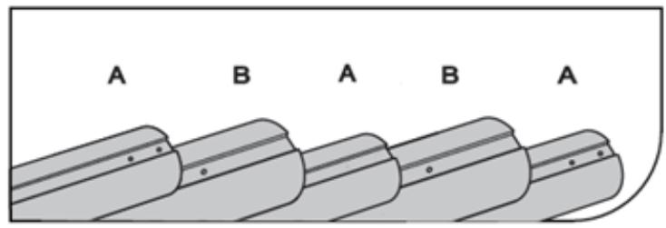
Technical diagram showing exploded view of mechanical components with numbered parts and exploded views

A B A B A

Obr. 3

A×1 B×1 C×1 D×1 L×6 M×2 J×2 K×2 Nx4 Rx3 O×18 Ex8 Fx8 Q×4 Px1 H×8 G×8

Obr. 4

#13 X2

#13 X2

Obr. 5

Mechanical component diagram showing two circular components with internal structure and directional arrows, no text or symbols present.

#9-4 b

#9-5 x4 #9-6 x4 C

#9-3 #9-1 #9-2 #9-3 d

Obr. 6

#2 # #8 # # # # # # # # # # # # # # # # # # # # # # # # # # # # # # # # # # # # # # # # # # # # # # # # # # # # # # # # # # # # # # # # # # # # # # # # # # # # # # # # # #5 # # # # # # # # # # # # # # # # # #17 #5

Obr. 7.

Diagram illustrating the assembly of a mechanical component with numbered parts and directional arrows indicating motion or assembly.

#21

Obr. 8.

#16 #11

#10 #20 #15

Obr. 9.

Z= MIN 45 cm Y= MIN 30 cm Y Y Z Z X

Z= MIN 45 cm Y= MIN 30 cm MAX 90 cm Z Y Y Z X

Obr. 10.

#14 30 cm #14 #14

#14 30 cm #14 #14

Obr. 11

Diagram showing two panels with curved arrows indicating rotation or movement (no text or symbols)

30cm 30cm X

Obr. 12.

Diagram of a mechanical assembly with directional arrows indicating motion or flow (no text or symbols present)

Obr. 13.

Pure electrical circuit lines without any symbols

Illustration of a mechanical clamp or bracket assembly with a handle and mounting base (no text or symbols)

Obr. 14.

Diagram of a mechanical device with a central component and multiple arms, no visible text or symbols

Technical line drawing of a mechanical clamp or bracket assembly (no text or symbols)

Obr. 15.

#7 X2

#7 X2

Obr. 16.

Technical diagram illustrating gear assembly with numbered components and directional arrows, including a close-up of the final gear assembly.

Obr. 17.

#5

Obr. 18

#10 #3

#4 #9

Obr. 19

Z=MIN 45 cm Y=MIN 30 cm
Y Z Y Z X

Z=MIN 45 cm Y=MIN 30 cm
MAX 90 cm Z Y Y Z X

Obr. 20.

Diagram showing airflow or heat transfer between two panels, one with curved arrows indicating direction (no text or symbols)

30cm 30cm X

Obr. 21

Diagram of a mechanical component with directional arrows indicating motion or flow (no text or symbols)

Obr.22

Pure schematic diagram of a mechanical device with no text, numbers, or symbols

Technical illustration of a mechanical clamp or bracket assembly (no text or symbols visible)

Obr. 23

Diagram of a mechanical device with a central component and two vertical supports, enclosed in a rectangular frame (no text or symbols)

Technical illustration of a mechanical clamp or bracket assembly (no text or symbols visible)

Obr. 24.

Technical diagram showing three different types of spray machines labeled A, B, and C, with D indicating a specific component.

Obr. 25

A L L B

Obr. 26.

Technical diagram showing mechanical assembly with labeled components A, B, and J, including a grid-like structure and a separate view of the same parts.

Obr. 27
| Dimension | Value | |---|---| | 1xP+1xR+1xQ | 137-202cm(54-79.5in) | | 1xR+2xQ | 210-275cm(82-108in) | | 1xP+2xR+2xQ | 242-372cm(95-146in) | | 2xR+3xQ | 315-445cm(124-175in) | | 3xR+4xQ | 420-615cm(165-242in) |

Obr. 28
P/Q R R P/Q O O O O O O P/Q R

Obr. 29.
M P/Q A M P/Q B

Obr. 30

L/N A J L B L/N N J

Obr. 31.

Technical diagram illustrating mechanical assembly with labeled components A and B, showing directional arrows and component movement.

Obr. 32.

H E G

Obr. 33

E F 15cm(6in) 15cm(6in) Y

Obr. 34.

Technical diagram of a mechanical device with two views: top shows a cylindrical component with attached pins, bottom shows a flat plate with labeled parts H and E (no text or symbols beyond labels)

Obr. 35

Technical diagram of a mechanical assembly with labeled parts E and H, showing internal components and connections (no text or symbols beyond labels)

Obr. 36

graph TD A["Component A"] --> B["Component B"] B --> C["Component C"] C --> D["Component D"] D --> E["Component E"] style A fill:#f9f,stroke:#333 style B fill:#ccf,stroke:#333 style C fill:#cfc,stroke:#333 style D fill:#fcc,stroke:#333

Uniprodo UNI_POOL_REEL_585 - UNI_POOL_REEL_585 - 54

3.2.2. UNI_POOL_REEL_570

3.2.3. UNI_POOL_REEL_585

Фиг. 2.
Technical diagram showing exploded view of mechanical components with numbered parts and exploded views

A B A B A

Фиг. 3
A×1 B×1 C×1 D×1 L×6 M×2 J×2 K×2 Nx4 Rx3 O×18 Ex8 Fx8 Q×4 Px1 H×8 G×8

Фиг. 4.
#13 X2

#13 X2

Фиг. 5.
Diagram of two circular mechanical components with directional arrows, no text or symbols present

#9-4 b

#9-5 x4 #9-6 x4 C

#9-3 #9-1 #9-2 #9-3 d

Фиг. 6.
graph TD A["Step #2"] --> B["Assembly #8"] B --> C["Step #4"] C --> D["Assembly #5"] D --> E["Step #17"] E --> F["Assembly #5"] style A fill:#f9f,stroke:#333 style B fill:#ccf,stroke:#333 style C fill:#cfc,stroke:#333 style D fill:#fcc,stroke:#333 style E fill:#cff,stroke:#333 style F fill:#ffc,stro…

Фиг. 7.
graph TD A["#1"] --> B["Engine"] B --> C["Engine 8"] C --> D["Engine 6"] D --> E["Engine 7"] E --> F["Engine 3"] F --> G["Engine 17"] G --> H["Engine 7"] style A fill:#f9f,stroke:#333 style B fill:#ccf,stroke:#333 style C fill:#cfc,stroke:#333 style D fill:#fcc,stroke:#333 style E fill:#cff,stroke:#…

#21

Фиг. 8.
#16 #11 #20 #15 #10

Фиг. 9.
Uniprodo UNI_POOL_REEL_585 - UNI_POOL_REEL_585 - 14

Фиг. 10.
#14 30 cm #14 #14

#14 30 cm #14 #14

Фиг. 11
Diagram showing two panels with curved arrows indicating rotation or movement (no text or symbols)

30cm 30cm X

Фиг. 12.

Diagram of a mechanical assembly with directional arrows indicating flow or movement (no text or symbols present)

Фиг. 13.

Pure electrical circuit lines without any symbols

Illustration of a mechanical clamp or bracket assembly with a handle and mounting base (no text or symbols)

Фиг. 14.

Diagram of a mechanical device with a central component and multiple arms, no visible text or symbols

Technical line drawing of a mechanical clamp or bracket assembly (no text or symbols)

Фиг. 15.

#7 X2

#7 X2

Фиг. 16.

Technical diagram illustrating gear assembly with labeled components and directional arrows, including parts #12 and #13.

Фиг. 17.

#5

Фиг. 18.

#10 #3

#4 #9

Фиг. 19

Z=MIN 45 cm Y=MIN 30 cm
Y Z Y Z X

Z=MIN 45 cm Y=MIN 30 cm
Z Y Y Z MAX 90 cm X

Фиг. 20.

Diagram showing airflow or heat transfer between two panels, one with curved arrows indicating direction (no text or symbols)

30cm 30cm X

Фиг. 21.

Diagram of a mechanical component with directional arrows indicating motion or flow (no text or symbols)

Фиг. 22.

Pure schematic diagram of a mechanical device with no text, numbers, or symbols

Technical illustration of a mechanical clamp or bracket assembly (no text or symbols visible)

Фиг. 23.

Diagram of a mechanical device with a central component and two vertical supports, enclosed in a rectangular frame (no text or symbols)

Technical illustration of a mechanical clamp or bracket assembly (no text or symbols visible)

Фиг. 24.

Technical diagram showing three different types of spray gun components labeled A, B, and C, with component D indicated.

Фиг. 25.

Technical diagram showing two types of hair feeders (A and B) with labeled parts and screw installation details.

Фиг. 26.

Technical diagram showing exploded and assembled views of electrical switchgear components with labeled parts A, B, and J.

Фиг. 27

| Dimension | Value | | :--- | :--- | | 1xP+1xR+1xQ | 137-202cm(54-79.5in) | | 1xR+2xQ | 210-275cm(82-108in) | | 1xP+2xR+2xQ | 242-372cm(95-146in) | | 2xR+3xQ | 315-445cm(124-175in) | | 3xR+4xQ | 420-615cm(165-242in) |

Фиг. 28.

P/Q R R P/Q O O O O O O P/Q R

Фиг. 29.

M P/Q A M M P/Q B

Фиг. 30

L/N A J L B L/N N J

Фиг. 31.

Technical diagram illustrating mechanical assembly with labeled components A and B, showing directional arrows and component movement.

Фиг. 32.

H E G

Фиг. 33

E F 15cm(6in) 15cm(6in) Y

Фиг. 34.

Technical diagram of a mechanical device with two views: top shows a cylindrical component with attached pins, bottom shows a flat plate with labeled parts H and E (no text or symbols beyond labels)

Фиг. 35.

Technical diagram of a mechanical device with labeled parts E and H, showing internal components and wiring (no text or symbols beyond labels)

Фиг. 36.

A ① J ②

Uniprodo UNI_POOL_REEL_585 - UNI_POOL_REEL_585 - 52

3.2.2. UNI_POOL_REEL_570

3.2.3. UNI_POOL_REEL_585

Eik. 2.
Technical diagram showing exploded view of mechanical components with numbered parts and exploded views

A B A B A

Elk. 3
A×1 B×1 C×1 D×1 L×6 M×2 J×2 K×2 Nx4 Rx3 O×18 Ex8 Fx8 Q×4 Px1 H×8 G×8

Eik. 4.
#13 X2

#13 X2

Elk. 5.

Mechanical diagram showing two circular components with internal structure and directional arrows, no text or symbols present.

#9-4 b

#9-5 x4 #9-6 x4 C

#9-3 #9-1 #9-2 #9-3 d

Εικ. 6.

graph TD A["Step 2: #2"] --> B["Step 3: #8"] B --> C["Step 4: #4"] C --> D["Step 5: #5"] D --> E["Step 17: #17"] style A fill:#f9f,stroke:#333 style E fill:#bbf,stroke:#333

Elk. 7.

Diagram illustrating the assembly of a mechanical component with numbered parts and directional arrows indicating motion or assembly.

#21

Eik. 8.

#16 #11

#10 #20 #15

Eik. 9.
Uniprodo UNI_POOL_REEL_585 - UNI_POOL_REEL_585 - 15

Εικ. 10.
#14 30 cm #14 #14

#14 30 cm #14 #14

Εικ. 11
Diagram showing two panels with curved arrows indicating rotation or movement (no text or symbols)

30cm 30cm X

Εικ. 12.

Diagram of a mechanical assembly with directional arrows indicating motion or flow (no text or symbols)

Εικ. 13.

Pure electrical circuit lines without any symbols

Technical illustration of a mechanical clamp or bracket assembly (no text or symbols visible)

Εικ. 14.

Diagram of a mechanical device with a central component and multiple arms, no visible text or symbols

Technical line drawing of a mechanical clamp or bracket assembly (no text or symbols)

Εικ. 15.

#7 X2

#7 X2

Eik. 16.

Technical diagram illustrating gear assembly with labeled components and directional arrows, including parts #12 and #13.

Εικ. 17.

#5

Εικ. 18.

#10 #3

#4 #9

Elk. 19

Z=MIN 45 cm Y=MIN 30 cm
Y Z Y Z X

Z=MIN 45 cm Y=MIN 30 cm
MAX 90 cm Y Z X

Εικ. 20.

Diagram showing airflow or heat transfer between two panels, one with curved arrows indicating direction (no text or symbols)

30cm 30cm X

Eik. 21.

Diagram of a mechanical component with directional arrows indicating motion or flow (no text or symbols)

Eik. 22.

Pure schematic diagram of a mechanical device with no text, numbers, or symbols

Technical illustration of a mechanical clamp or bracket assembly (no text or symbols visible)

Eik. 23.

Diagram of a mechanical device with a central component and two vertical supports, enclosed in a rectangular frame (no text or symbols)

Technical illustration of a mechanical clamp or bracket assembly (no text or symbols visible)

Eik. 24.

Technical diagram showing three different types of spray gun components labeled A, B, and C, with component D indicated.

Eik. 25.

Technical diagram showing two types of hair feeders (A and B) with labeled parts and screw installation details.

Εικ. 26.

Technical diagram showing exploded and assembled views of electrical switchgear components with labeled parts A, B, and J.

Eik. 27
| Dimension | Value | | :--- | :--- | | 1xP+1xR+1xQ | 137-202cm(54-79.5in) | | 1xR+2xQ | 210-275cm(82-108in) | | 1xP+2xR+2xQ | 242-372cm(95-146in) | | 2xR+3xQ | 315-445cm(124-175in) | | 3xR+4xQ | 420-615cm(165-242in) |

Eik. 28.
P/Q R R P/Q O O O O O O P/Q R

Eik. 29.
M P/Q A M M P/Q B

Eik. 30

L/N A J L B L/N N J

Elk. 31.

Technical diagram illustrating mechanical assembly with labeled components A and B, showing directional arrows and component movement.

Εικ. 32.

H E G

Eik. 33

E F 15cm(6in) 15cm(6in) Y

Elk. 34.

Technical diagram showing a mechanical device with a spring and a base plate, alongside its schematic view (no text or symbols present)

Eik. 35.

Technical diagram of a mechanical device with labeled parts E and H, showing internal components and wiring (no text or symbols beyond labels)

Elk. 36.

A ① J ②

Uniprodo UNI_POOL_REEL_585 - UNI_POOL_REEL_585 - 53

3.2.2. UNI_POOL_REEL_570

  1. (Pogledajte sl. 15) Pričvrstite osovine valjka s vijcima (7) na vanjske cijevi tipa A.

  2. (Pogledajte sl. 16) Postavite kotače (13) na osovine temeljne grede (2), umetnite rolu (12) u središte kotača i učvrstite spoj podloškom i čepom.

  3. (Pogledajte sl. 17) Umetnite rolu u šipku, a zatim pričvrstite oba dijela u kotač za pogon valjka (5). Osigurajte spoj utikačem.

  4. (Pogledajte sl. 18) Provucite osovinu valjka (3) kroz fiksni oslonac (2) i postavite kotač na njega za pogon valjka (5). Osigurajte spoj vijkom i maticom (10). U gornji dio fiksnog nosača (2) postavite stezni vijak.

Provucite osovinu valjka (4) kroz rupu u pokretnom nosaču (1) i montirajte podlošku (11) i držač (6) na nju. Osigurajte spoj vijkom i maticom (9).

  1. (Pogledajte sl. 19) Oba nosača postavite ne bliže od 45 cm od suprotnih strana bazena. U slučaju pravokutnog bazena, valjak treba postaviti uz kraći rub. U slučaju bazena ovalnog oblika, valjak treba postaviti iznad vodene površine najviše 90 cm od ruba.

Spojite cijevi valjka tako da njihovo minimalno preklapanje ne bude manje od 30 cm.

  1. (Pogledajte sl. 20) Odspojite muške čičak trake (15) od ženskih čičak traka (14), uklonite ljepljivi zaštitni sloj. Zalijepite muške čičak dijelove (15) na valjak, okomito na njegovu osovinu u pravilnim razmacima, duž cijele dužine bazena. Velcro trake ne smiju biti postavljene bliže od 30 cm od spojeva cijevi.

  2. (Pogledajte sl. 21) Postavite stezaljku (16) i kopču (17) na remen.

  3. (Pogledajte sl. 22) U slučaju pravokutnih bazena:

Raširite pokrivač preko bazena. Montirajte kopče (17) (kao što je prikazano na slici) za pokrivanje u pravilnim razmacima na udaljenosti kao muški čičak dijelovi (15) na valjak. Uvjerite se da duljina remena omogućuje da pokrivač ravno leži na površini bazena kako biste izbjegli puhanje zraka ispod pokrivača.

  1. (Pogledajte sl. 23) Za okrugle ili ovalne bazene:

Raširite pokrivač preko bazena. Montirajte kopče (17) (kao što je prikazano na slici) za pokrivanje u pravilnim razmacima na udaljenosti kao muški čičak dijelovi (15) na valjak. Uvjerite se da duljina remena omogućuje da pokrivač ravno leži na površini bazena kako biste izbjegli puhanje zraka ispod pokrivača.

3.2.3. UNI_POOL_REEL_585

  1. (Pogledajte sl. 24) Umetnite poluge (D) u nosač (A), zatim gurnite držač (C) u nosač (B).
  2. (Pogledajte sl. 25) Uvrnite vijak (L) u rupu u bazi (A) i (B). Preporučljivo je koristiti odvijač s magnetskim vrhom koji će držati vijak tijekom montaže.
  3. (Pogledajte sl. 26) Potrebna duljina valjka označena je kao udaljenost X od unutarnje strane nosača (A) do unutarnje strane drugog nosača (B) kada su oba nosača postavljena na suprotnim stranama bazena.

Za mjerenje udaljenosti X za bazene s ravnim rubom:

a) Umetnite baze (J) u dno nosača (A) i (B).
b) Postavite nosače (A) i (B) na rub.
c) Izmjerite udaljenost između unutarnjih strana nosača (A) i (B).

Za mjerenje udaljenosti X za bazene s obalama u obliku cjevastog okvira:

a) Umetnite baze (K) u dno nosača (A) i (B).
b) Postavite nosače (A) i (B) na cjevasti okvir i osigurajte njihov položaj zatezanjem vijaka na bazama (K).
c) Izmjerite udaljenost između unutarnjih strana nosača (A) i (B).

  1. (Vidi sl. 27) Moguća konfiguracija spoja cijevi

NAPOMENA: Minimalno preklapanje cijevi je 20 cm (8 in)

Slika 2.
Technical diagram showing exploded view of mechanical components with numbered parts and exploded views

A B A B A

Slika 3
A×1 B×1 C×1 D×1 L×6 M×2 J×2 K×2 Nx4 Rx3 O×18 Ex8 Fx8 Q×4 Px1 H×8 G×8

Slika 4.
#13 X2

#13 X2

Slika 5.
Diagram of two circular mechanical components with directional arrows, no text or symbols present

#9-4 b

#9-5 x4 #9-6 x4 C

#9-3 #9-1 #9-2 #9-3 d

Slika 6.
graph TD A["Step #2"] --> B["Assembly #8"] B --> C["Step #4"] C --> D["Assembly #5"] D --> E["Step #17"] E --> F["Assembly #5"] style A fill:#f9f,stroke:#333 style B fill:#ccf,stroke:#333 style C fill:#cfc,stroke:#333 style D fill:#fcc,stroke:#333 style E fill:#cff,stroke:#333 style F fill:#ffc,stro…

Slika 7.
graph TD A["Component #1"] --> B["Part with roller"] B --> C["Component #8"] C --> D["Part with roller"] D --> E["Component #6"] E --> F["Part with roller"] F --> G["Component #7"] G --> H["Part with wheel"] H --> I["Component #3"] I --> J["Part with wheel"] J --> K["Component #17"] K --> L["Part wi…

#21

Slika 8.
#16 #11 #20 #15 #10

Slika 9.
Uniprodo UNI_POOL_REEL_585 - UNI_POOL_REEL_585 - 14

Slika 10.
#14 30 cm #14 #14

#14 30 cm #14 #14

Slika 11
Diagram showing two panels with curved arrows indicating rotation or movement (no text or symbols)

30cm 30cm X

Slika 12.

Diagram of a mechanical assembly with directional arrows indicating motion or flow (no text or symbols present)

Slika 13.

Pure electrical circuit lines without any symbols

Technical illustration of a mechanical clamp or bracket assembly (no text or symbols visible)

Slika 14.

Diagram of a mechanical device with a central component and multiple arms, no visible text or symbols

Technical line drawing of a mechanical clamp or bracket assembly (no text or symbols)

Slika 15.

#7 X2

#7 X2

Slika 16.

Diagram illustrating mechanical assembly steps with labeled components and directional arrows, including parts #12 and #13.

Slika 17.

#5

Slika 18.

#10 #3

#4 #9

Slika 19

Z=MIN 45 cm Y=MIN 30 cm
Y Z Y Z X

Z=MIN 45 cm Y=MIN 30 cm
Z Y Y Z MAX 90 cm X

Slika 20.

Diagram showing airflow or heat transfer between two panels, one with curved arrows indicating direction (no text or symbols)

30cm 30cm X

Slika 21.

Diagram of a mechanical component with directional arrows indicating motion or flow (no text or symbols)

Slika 22.

Pure schematic diagram of a mechanical device with no text, numbers, or symbols

Pure mechanical assembly diagram showing a clamping device attached to a base plate (no text or symbols)

Slika 23.

Diagram of a mechanical device with a central component and two vertical supports, enclosed in a rectangular frame (no text or symbols)

Technical illustration of a mechanical clamp or bracket assembly (no text or symbols visible)

Slika 24.

Technical diagram showing three different types of spray gun components labeled A, B, and C, with component D indicated.

Slika 25.

Technical diagram showing two types of hair feeders (A and B) with labeled parts and screw installation details.

Slika 26.

Technical diagram showing exploded and assembled views of electrical switchgear components with labeled parts A, B, and J.

Slika 27
| Dimension | Value | |---|---| | 1xP+1xR+1xQ | 137-202cm(54-79.5in) | | 1xR+2xQ | 210-275cm(82-108in) | | 1xP+2xR+2xQ | 242-372cm(95-146in) | | 2xR+3xQ | 315-445cm(124-175in) | | 3xR+4xQ | 420-615cm(165-242in) |

Slika 28.
P/Q R R P/Q O O O O O O P/Q R

Slika 29.
M P/Q A M M P/Q B

Slika 30

L/N A J L N B L/N J

Slika 31.

Technical diagram illustrating mechanical assembly with labeled components A and B, showing directional arrows and component movement.

Slika 32.

H E G

Slika 33

E F 15cm(6in) 15cm(6in) Y

Slika 34.

Technical diagram of a mechanical device with two views: top shows a cylindrical component with attached pins, bottom shows a flat plate with labeled parts H and E (no text or symbols beyond labels)

Slika 35.

Technical diagram of a mechanical device with labeled parts E and H, showing internal components and wiring (no text or symbols beyond labels)

Slika 36.

A ① J ②

Uniprodo UNI_POOL_REEL_585 - UNI_POOL_REEL_585 - 52

3.2.2. UNI_POOL_REEL_570

3.2.3. UNI_POOL_REEL_585

2 pav.

Technical diagram showing exploded view of mechanical components with numbered parts and exploded views

A B A B A

3 pav

A×1 B×1 C×1 D×1 L×6 M×2 J×2 K×2 Nx4 Rx3 O×18 Ex8 Fx8 Q×4 Px1 H×8 G×8

4 pav.

#13 X2

#13 X2

5 pav.

Mechanical diagram showing two circular components with internal structure and directional arrows, no text or symbols present.

#9-4 b

#9-5 x4 #9-6 x4 C

#9-3 #9-1 #9-2 #9-3 d

6 pav.

graph TD A["Step #2"] --> B["Assembly #8"] B --> C["Step #4"] C --> D["Assembly #5"] D --> E["Step #17"] E --> F["Assembly #5"] style A fill:#f9f,stroke:#333 style B fill:#ccf,stroke:#333 style C fill:#cfc,stroke:#333 style D fill:#fcc,stroke:#333 style E fill:#cff,stroke:#333 style F fill:#ffc,stro…

7 pav.

Diagram illustrating the assembly of a mechanical component with numbered parts and directional arrows indicating motion or assembly.

#21

8 pav.

#16 #11

#10 #20 #15

9 pav.

Z= MIN 45 cm Y= MIN 30 cm Y Y Z Z X

Z= MIN 45 cm Y= MIN 30 cm MAX 90 cm Z Y Y Z X

10 pav.

#14 30 cm #14 #14

#14 30 cm #14 #14

11 pav

Diagram showing two panels with curved arrows indicating rotation or flow, no text or symbols present

30cm 30cm X

12 pav.

Diagram of a mechanical assembly with directional arrows indicating motion or flow (no text or symbols)

13 pav.

Pure electrical circuit lines without any symbols

Technical illustration of a mechanical clamp or bracket assembly (no text or symbols visible)

14 pav.

Diagram of a mechanical device with a central component and multiple arms, no visible text or symbols

Technical line drawing of a mechanical clamp or bracket assembly (no text or symbols)

15 pav.

#7 X2

#7 X2

16 pav.

Technical diagram illustrating gear assembly with numbered components and directional arrows, including a close-up of the final gear assembly.

17 pav.

#5

18 pav.

#10 #3

#4 #9

19 pav

Z=MIN 45 cm Y=MIN 30 cm
Y Z Y Z X

Z=MIN 45 cm Y=MIN 30 cm
MAX 90 cm Y Z X

20 pav.

Diagram showing airflow or heat transfer between two panels, one with curved arrows indicating direction (no text or symbols)

30cm 30cm X

21 pav.

Diagram of a mechanical component with directional arrows indicating motion or flow (no text or symbols)

22 pav.

Pure schematic diagram of a mechanical device with no text, numbers, or symbols

Diagram of a mechanical clamp or bracket assembly with a handle and mounting base (no text or symbols)

23 pav.

Diagram of a mechanical device with a central component and two vertical supports, enclosed in a rectangular frame (no text or symbols)

Technical illustration of a mechanical clamp or bracket assembly (no text or symbols visible)

24 pav.

Technical diagram showing three different types of spray machines labeled A, B, and C, with D indicating a specific component.

25 pav.

Technical diagram showing two types of hair tools labeled A and B, with screw being inserted into a spring (A) and then being inserted into a screw (B), with arrows indicating the process.

26 pav.

Technical diagram showing assembly of mechanical components with labeled parts A, B, and J, including a schematic view of a device with x-axis.

27 pav
| Dimension | Value | | :--- | :--- | | 1xP+1xR+1xQ | 137-202cm(54-79.5in) | | 1xR+2xQ | 210-275cm(82-108in) | | 1xP+2xR+2xQ | 242-372cm(95-146in) | | 2xR+3xQ | 315-445cm(124-175in) | | 3xR+4xQ | 420-615cm(165-242in) |

28 pav.
P/Q R R P/Q O O O O O O P/Q R

29 pav.
M P/Q A M P/Q B

30 pav

L/N A J L B L/N N J

31 pav.

Technical diagram illustrating mechanical assembly with labeled components A and B, showing directional arrows and component movement.

32 pav.

H E G

33 pav

E F 15cm(6in) 15cm(6in) Y

34 pav.

Technical diagram of a mechanical device with two views: one showing a spring-loaded mechanism and the other showing a flat plate with labeled parts H and E (no text or symbols beyond labels)

35 pav.

Technical diagram of a mechanical device with labeled components (E and H), showing internal structure and wiring (no text or symbols beyond labels)

36 pav.

A ① J ②

Uniprodo UNI_POOL_REEL_585 - UNI_POOL_REEL_585 - 54

3.2.2. UNI_POOL_REEL_570

3.2.3. UNI_POOL_REEL_585

Fig. 2.
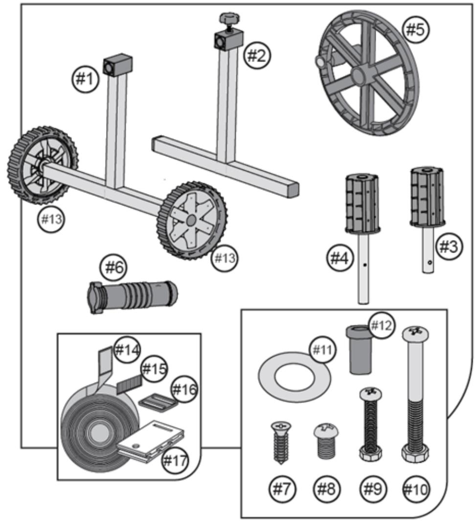
Technical diagram showing exploded view of mechanical components with numbered parts and exploded views

A B A B A

Fig. 3
A×1 B×1 Cx1 D×1 L×6 M×2 J×2 K×2 Nx4 Rx3 O×18 Ex8 Fx8 Q×4 Px1 H×8 G×8

Fig. 4.
#13 X2

#13 X2

Fig. 5.
Mechanical diagram showing two circular components with internal structure and directional arrows, no text or symbols present.

#9-4 b

#9-5 x4 #9-6 x4 C

#9-3 #9-1 #9-2 #9-3 d

Fig. 6.
graph TD A["Step #2"] --> B["Assembly #8"] B --> C["Step #4"] C --> D["Assembly #5"] D --> E["Step #17"] E --> F["Assembly #5"] style A fill:#f9f,stroke:#333 style B fill:#ccf,stroke:#333 style C fill:#cfc,stroke:#333 style D fill:#fcc,stroke:#333 style E fill:#cff,stroke:#333 style F fill:#ffc,stro…

Fig. 7.
graph TD A["#1"] --> B["Engine"] B --> C["Engine 8"] C --> D["Engine 6"] D --> E["Engine 7"] E --> F["Engine 3"] F --> G["Engine 17"] G --> H["Engine 7"] style A fill:#f9f,stroke:#333 style B fill:#ccf,stroke:#333 style C fill:#cfc,stroke:#333 style D fill:#fcc,stroke:#333 style E fill:#cff,stroke:#…

#21

Fig. 8.
#16 #11 #20 #15 #10

Fig. 9.
Uniprodo UNI_POOL_REEL_585 - UNI_POOL_REEL_585 - 14

Fig. 10.
#14 30 cm #14 #14

#14 30 cm #14 #14

Fig. 11
Diagram showing two panels with curved arrows indicating rotation or movement (no text or symbols)

30cm 30cm X

Fig. 12.
Diagram of a mechanical assembly with directional arrows indicating flow or movement (no text or symbols present)

Fig. 13.
Pure electrical circuit lines without any symbols

Technical illustration of a mechanical clamp or bracket assembly (no text or symbols visible)

Fig. 14.
Pure mechanical diagram of a cylindrical device with attached clamps and a central base, without any text, numbers, or symbols.

Technical line drawing of a mechanical clamp or bracket assembly (no text or symbols)

Fig. 15.
#7 X2

#7 X2

Fig. 16.
Technical diagram illustrating gear assembly with labeled components and directional arrows, including parts #12 and #13.

Fig. 17.

#5

Fig. 18.
#10 #3

#4 #9

Fig. 19
Z= MIN 45 cm Y= MIN 30 cm Z Y Y Z X

Z= MIN 45 cm Y= MIN 30 cm MAX 90 cm Z Y Y Z X

Fig. 20.
Diagram showing airflow or heat transfer between two panels, with arrows indicating direction (no text or symbols)

30cm 30cm X

Fig. 21.
Diagram of a mechanical component with directional arrows indicating motion or flow (no text or symbols)

Fig. 22.
Pure schematic diagram of a mechanical device with no text, numbers, or symbols

Diagram of a mechanical clamp or bracket assembly with a handle, no text or symbols present

Fig. 23.
Pure diagram of a mechanical or electrical component with no text, numbers, or symbols

Technical illustration of a mechanical clamp or bracket assembly (no text or symbols visible)

Fig. 24.
Technical diagram showing three different types of spray gun components labeled A, B, and C, with component D indicated.

Fig. 25.
Technical diagram showing two types of hair feeders (A and B) with labeled parts and screw installation details.

Fig. 26.

Technical diagram showing exploded and assembled views of electrical switchgear components with labeled parts A, B, and J.

Fig. 27
| Dimension | Value | |---|---| | 1xP+1xR+1xQ | 137-202cm(54-79.5in) | | 1xR+2xQ | 210-275cm(82-108in) | | 1xP+2xR+2xQ | 242-372cm(95-146in) | | 2xR+3xQ | 315-445cm(124-175in) | | 3xR+4xQ | 420-615cm(165-242in) |

Fig. 28.
P/Q R R P/Q O O O O O O P/Q R

Fig. 29.
M P/Q A M M P/Q B

Fig. 30
L/N A J L B L/N N J

Fig. 31.
Technical diagram illustrating mechanical assembly with labeled components A and B, showing directional arrows and component movement.

Fig. 32.
H E G

Fig. 33
E F 15cm(6in) 15cm(6in) Y

Fig. 34.
Technical diagram of a mechanical device with two views: top shows a cylindrical component with attached pins, bottom shows a flat plate with labeled parts H and E (no text or symbols beyond labels)

Fig. 35.
Technical diagram of a mechanical device with labeled components (E and H), showing internal structure and wiring (no text or symbols beyond labels)

Fig. 36.
A ① J ②

Uniprodo UNI_POOL_REEL_585 - UNI_POOL_REEL_585 - 52

3.2.2. UNI_POOL_REEL_570

  1. (Glejte sliko 15) Privijte osi valja z vijaki (7) na zunanje cevi tipa A.

  2. (Glejte sliko 16) Postavite kolesa (13) na osi osnovnega nosilca (2), vstavite zvitek (12) v sredino koles in pritrdite povezavo s podložko in čepom.

  3. (Glejte sliko 17) Vstavite zvitek v palico in nato oba dela pritrdite na kolo, da poganjate zvitek (5). Priključek zavarujte z vtičem.

  4. (Glejte sliko 18) Postavite os valja (3) skozi fiksno oporo (2) in nanjo namestite kolo za pogon valja (5). Zavarujte povezavo z vijakom in matico (10). V zgornjem delu fiksnega nosilca (2) namestite vpenjalni vijak.

Skozi luknjo v premičnem nosilcu (1) potisnite os valja (4) in nanjo namestite podložko (11) in držalo (6). Zavarujte povezavo z vijakom in matico (9).

3.2.3. UNI_POOL_REEL_585

Slika 2.
Technical diagram showing exploded view of mechanical components with numbered parts and exploded views

A B A B A

Slika 3
A×1 B×1 Cx1 D×1 L×6 M×2 J×2 K×2 Nx4 Rx3 O×18 Ex8 Fx8 Q×4 Px1 H×8 G×8

Slika 4.
#13 X2

#13 X2

Slika 5.

Mechanical diagram showing two circular components with internal structure, connected by a dashed line and labeled 'a' (no text or symbols on the diagrams themselves)

#9-4 b

#9-5 x4 #9-6 x4 C

#9-3 #9-1 #9-2 #9-3 d

Slika 6.

#2 # #8 # # # # # # # # # # # # # # # # # # # # # # # # # # # # # # # # # # # # # # # # # # # # # # # # # # # # # # # # # #5 # # # # # # # # # # # # # # # # # # # # # #17 #5

Slika 7.
Diagram illustrating the assembly of a mechanical component with numbered parts and directional arrows indicating motion or assembly.

#21

Slika 8.
#16 #11 #20 #15 #10

Slika 9.
Uniprodo UNI_POOL_REEL_585 - UNI_POOL_REEL_585 - 14

Slika 10.
#14 30 cm #14 #14

#14 30 cm #14 #14

Slika 11
Diagram showing two panels with curved arrows indicating rotation or movement (no text or symbols)

30cm 30cm X

Slika 12.

Diagram of a mechanical assembly with directional arrows indicating motion or flow (no text or symbols present)

Slika 13.

Pure electrical circuit lines without any symbols

Technical illustration of a mechanical clamp or bracket assembly (no text or symbols visible)

Slika 14.

Diagram of a mechanical device with a central component and multiple arms, no visible text or symbols

Technical line drawing of a mechanical clamp or bracket assembly (no text or symbols)

Slika 15.

#7 X2

#7 X2

Slika 16.

Technical diagram illustrating gear assembly with labeled components and directional arrows, including parts #12 and #13.

Slika 17.

#5

Slika 18.

#10 #3

#4 #9

Slika 19

Z=MIN 45 cm Y=MIN 30 cm
Y Z Y Z X

Z=MIN 45 cm Y=MIN 30 cm
MAX 90 cm Z Y Y Z X

Slika 20.

Diagram showing airflow or heat transfer between two panels, one with curved arrows indicating direction (no text or symbols)

30cm 30cm X

Slika 21.

Diagram of a mechanical component with directional arrows indicating motion or flow (no text or symbols)

Slika 22.

Pure schematic diagram of a mechanical device with no text, numbers, or symbols

Diagram of a mechanical clamp or bracket assembly with a handle and mounting base (no text or symbols)

Slika 23.

Diagram of a mechanical device with a central component and two vertical supports, enclosed in a rectangular frame (no text or symbols)

Technical illustration of a mechanical clamp or bracket assembly (no text or symbols visible)

Slika 24.

Technical diagram showing three different types of spray gun components labeled A, B, and C, with component D indicated.

Slika 25.

Technical diagram showing two types of hair feeders (A and B) with labeled parts and screw installation details.

Slika 26.

Technical diagram showing exploded and assembled views of electrical switchgear components with labeled parts A, B, and J.

Slika 27
| Dimension | Value | |---|---| | 1xP+1xR+1xQ | 137-202cm(54-79.5in) | | 1xR+2xQ | 210-275cm(82-108in) | | 1xP+2xR+2xQ | 242-372cm(95-146in) | | 2xR+3xQ | 315-445cm(124-175in) | | 3xR+4xQ | 420-615cm(165-242in) |

Slika 28.
P/Q R R P/Q O O O O O O P/Q R

Slika 29.
M P/Q A M M P/Q B

Slika 30

L/N A J L N B L/N J

Slika 31.

Technical diagram illustrating mechanical assembly with labeled components A and B, showing directional arrows and component movement.

Slika 32.

H E G

Slika 33

E F 15cm(6in) 15cm(6in) Y

Slika 34.

Technical diagram of a mechanical device with two views: one showing a spring-loaded mechanism and the other showing a flat plate with labeled parts H and E (no text or symbols beyond labels)

Slika 35.

Technical diagram of a mechanical device with labeled parts E and H, showing internal components and wiring (no text or symbols beyond labels)

Slika 36.

A ① J ②

For the disposal of the device please consider and act according to the national and local rules and regulations.

CONTACT

expondo Polska sp. z o.o. sp. k.

Manual assistant
Powered by Anthropic
Waiting for your message
Product information

Brand : Uniprodo

Model : UNI_POOL_REEL_585

Category : Washing machine