
BBY180 - Electric bike MAKITA - Free user manual and instructions
Find the device manual for free BBY180 MAKITA in PDF.


| Product Type | Electric Bike |
| Brand | Makita |
| Model | BBY180 |
| Battery Voltage | 18 V |
| Battery Type | Lithium-ion (Makita LXT) |
| Battery Capacity | 5 Ah (estimated) |
| Range | Approximately 40 km |
| Motor | 250 W, rear wheel |
| Maximum speed | 25 km/h |
| Dimensions (L x H x W) | 170 x 58 x 105 cm |
| Weight | 22 kg (with battery) |
| Frame | Lightweight aluminum |
| Brakes | Mechanical disc brakes |
| Transmission | Belt (maintenance-free) |
| Tires | 26 x 1.75", puncture-resistant |
| Lighting | Front and rear LED lights |
| Display | LCD screen with speedometer |
| Maintenance | Clean with damp cloth, regularly check brakes and tires |
| Safety | Wear a helmet, obey traffic rules |
| Spare parts | Batteries, charger, tires, brakes available online |
Frequently Asked Questions - BBY180 MAKITA
User questions about BBY180 MAKITA
0 question about this device. Answer the ones you know or ask your own.
Ask a new question about this device
Download the instructions for your Electric bike in PDF format for free! Find your manual BBY180 - MAKITA and take your electronic device back in hand. On this page are published all the documents necessary for the use of your device. BBY180 by MAKITA.
USER MANUAL BBY180 MAKITA

1

2

3

4

5
6

7

8

9
10

11 12


13 14


15 16

17 18

19 20


21
ENGLISH (Original instructions)
Explanation of general view
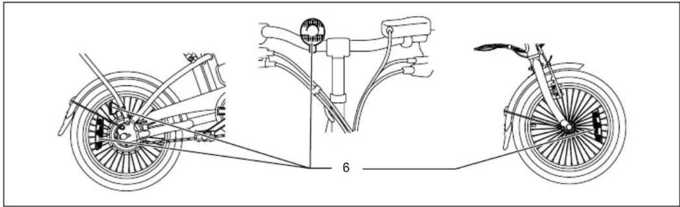
| 1. Red part | 10. Locknut | 19. Brake spoke support |
| 2. Assist display | 11. Close direction | 20. Brake arm |
| 3. Power display | 12. Self-locking slider | 21. Brake cable |
| 4. ON/OFF button | 13. Hook | 22. Brake broad |
| 5. Correct | 14. Folding handle | 23. Spring screw |
| 6. Reflector | 15. Frame | 24. Sliding parts |
| 7. Seat clamp | 16. Folding locking buckle | 25. Adjust screw |
| 8. Safety Line | 17. Screw | 26. Brake cable fix board |
| 9. Quick release lever | 18. Brake support |
Specifications
| Model BBY180 | ||
| Motor | Output 100 W | |
| Model DC brushless motor | ||
| Rated voltage D.C. 18 V | ||
| Dimensions | Length 1,450 mm | |
| Width 570 mm | ||
| Seat height 670 mm - 910 mm | ||
| Distance between wheel axes 975 mm | ||
| Tire size 16 inch | ||
| Weight*1 | 20.8 kg | |
| Battery | Model BL1830/BL1815 | |
| Capacity 3.0/1.3 Ah | ||
| Kind | Li-ion | |
| Cruising distance*2 | Approx. 8.5 km(BL1830 1 piece) | |
| Control type | Pedal speed sensor type | |
| Speed range for assist | 0 - 16 (km/h) | |
| Brake type | Front | V brake |
| Rear | Drum brake | |
- Due to our continuing programme of research and development, the specifications herein are subject to change without notice.
*1: With two battery BL1830
*2: Measuring range condition of cruising distance: Assist level 3, Loading capacity 75 kg, no wind, concrete flat ground
Please read carefully before using BBY180:
- Please read the manual and check all the parts and accessories carefully before use.
- The rider has to comply with the road regulations according to each country's requirement.
- Do not ride on the streets exclusive to cars. Make sure to ride safely.
- Have to use the specified battery, motor, controller and other electric parts, if need any change, please contact our agent.
- Insure the safety, do not lend BBY180 to other person especially pregnant women or somebody who cannot ride the bicycle.
-
BBY180 can be used under wet, raining, snowing weather, but make sure to ride slowly, do not cross the water over 150 mm of depth to avoid the electric parts getting damage by water.
-
Implement standard: EN15194
Max loading weight: 100 KG
Do not dispose of the battery.
• The assisted speed cannot exceed 16 Km/h.
For the safety use, please let our sales staff adjust the seat to a comfortable position.
- Warning: The safety line of the seat post should be below under into the frame.
- Check the function before use.
- Please park the bicycle on even road and do not block traffic.
- Comply with road regulations.
- Ride it on non-motor roads.
-
Wear a safety helmet when ride the bicycle.
-
BBY180 requires less pedal power than a normal bicycle to move. However, until the cyclist gets used to lighter pedaling, he or she may pedal too powerfully, causing faster speeds than a normal bicycle, which may lead to accidents, such as a fall or crash.
- Do not ride the bicycle across extremely bumpy surfaces (pavement curbstones, drainage runs, etc.).
- When bringing the bicycle to a halt, apply both front and rear brakes.
- Do not ride the bicycle when there is a problem with it.
- Do not dismantle or lubricate the parts comprising the power assist system.
- Do not remodel the bicycle by yourself.
- Only use genuine parts as accessories or replacements.
- After removing/replacing wheel(s) or adjusting the saddle, always check that relevant bolts have been tightened before riding the bicycle.
- Never ride the bicycle with the saddle or handlebar higher than the limit line.
- Do not lubricate brake, tires or rims in damping areas.
1. Check before use.
For the safety use, please check the following before use it.
a. Check if the tires and screws work well.
b. Brake system: When the brake level reaches its 1/2 range, the brakes have to stop the bicycle completely.
c. Power system: Check if the battery is fixed well, and the power is full for use.
2. Attention:
a. Please decelerate when turning and going downhills.
Article 1. To the customer
a. Thanks for selecting our BBY180, and we wish it could bring you an excellent riding experience.
b. Please read the manual carefully before using BBY180. If any questions, please contact one of our agent without hesitation.
Article 2. Introduction of BBY180
1. To secure your safety, please check the product before use.
a. Does the brake system work well?
b. Does the E-system work well? (Ref: 3.3)
c. Are the handlebar and saddle in position and locked well?
d. Is the tire pressure normal?
e. Are the Folding handle and pedals locked well?
2. BBY180
a. This product is designed for the customer's easy operation.
b. BBY180 could protect the battery under a over-current or low voltage situation.
c. The front brake and band brake provide safe functions.
d. Within one year, the regular usage range could comply with the EN15194 requirement.
3. Operation
3.1 How to adjust your position on the bicycle
- Measure your height. (Fig. 1)
- Refer to the bicycle's settings table.
| S (cm) Hs (cm) H (cm) | |
| 155 – 159 55.5 | +12 |
| 160 – 164 58 | |
| 165 – 169 60 | |
| 170 – 174 62.5 | |
| 175 – 179 64.5 | |
| 180 – 184 67 | |
| 185 – 190 69.5 |
(Fig. 2) (Fig. 3)
3. Adjust your bicycle. (Fig. 2 - 3)
Warning
- Do not ride the bicycle when the safety lines on the seat or handles are visible.
Adjusting the seat
Minimum seat height is the height determined when the position of the seat is lowered and the clamp is locked.
Practical Information
Depending on the terrain you are travelling on, the seat height can be modified:
- On a flat ground or when climbing, the seat should be in a high position for the greater efficiency.
- When travelling downhill, the seat should be slightly lowered to improve bicycle control and to make it easier to go over or circumvent obstacles.
3.2 Introduction of battery: Use and care for BBY180
- Remove the battery from BBY180 when not in use.
- Recharge only with the charger specified by the manufacturer. A charger that is suitable for only one type of battery pack may create a risk of fire when used with another battery pack.
- Use BBY180 only with specifically designated battery packs. Use of any other battery packs may create a risk of injury and fire.
- When the battery pack is not in use, keep it away from metal objects, like paper clips, coins, keys, nails, screws or other small metal objects, which can make a conductive connection from one terminal to another. Shorting both the battery under abusive conditions, terminals may cause burns or a fire.
- As liquid may leak from the battery, avoid contact. If you touch it accidentally, flush with water. If the liquid contacts with eyes, seek medical help. Liquid leaked from the battery may cause irritation or burns.
IMPORTANT SAFETY INSTRUCTIONS
For battery cartridge
- Before using battery cartridge, read all instructions and cautionary markings on the (1) battery charger, (2) battery, and (3) product the battery is used for.
-
Do not disassemble the battery cartridge.
-
If operating time has become excessively shorter, stop operating immediately. It may result in a risk of overheating, possible burns and even an explosion.
- If the electrolyte gets into your eyes, rinse it out with clear water and seek medical attention right away. It may result in loss of your eyesight.
- Do not short the battery cartridge:
(1) Do not touch the terminals with any conductive materials.
(2) Avoid storing battery cartridge in a container with other metal objects such as nails, coins, etc.
(3) Do not expose the battery cartridge to water or rain.
A battery short can cause a large current flow, overheating, possible burns and even a brakedown.
- Do not store BBY180 and battery cartridge in locations where the temperature may reach or exceed 50°C (122°F).
- Do not incinerate the battery cartridge even if it is severely damaged or is completely worn out. The battery cartridge can explode in a fire.
- Be careful not to drop or strike the battery.
- Do not use a dropped or struck battery.
SAVE THESE INSTRUCTIONS.
Tips for maintaining a maximum battery life
- Never recharge a fully charged battery cartridge.
Overcharging shortens the battery service life. - Charge the battery cartridge with a room temperature at 10°C - 40°C (50°F - 104°F).
Let a hot battery cartridge cool down before charging it.
Instruction of installing or removing battery cartridge
Installing battery cartridge
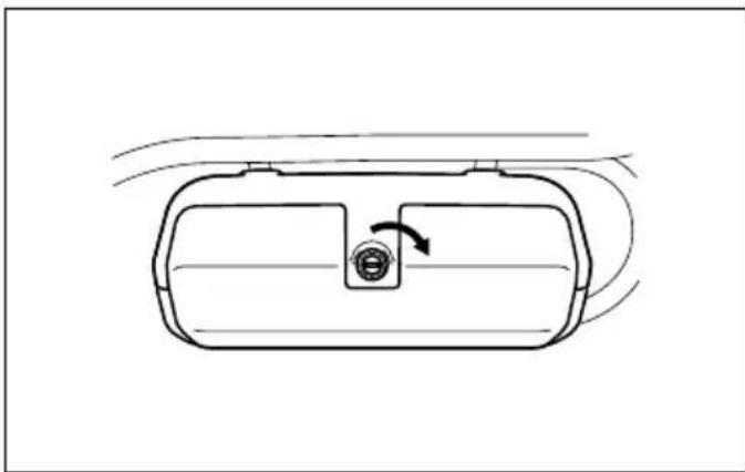
Insert the key into the key hole and turn the key counter clockwise 90°. (Fig. 4)
Open the cover and always insert the battery cartridge all the way until it locks in place with a little click.
If you can see the red part on the upper side of the button, it is not locked completely. Insert it fully until the red part cannot be seen. (Fig. 5 & 7)
Close the cover and insert the key to the key hole and turn the key to clockwise 90°. (Fig. 6)
NOTE:
Even with one battery cartridge, the assisting function works, but the total battery life will be half compared with that when using two battery cartridges.
Removing battery cartridge
Open the cover with the key.
To remove the battery cartridge, withdraw it from the tool while sliding the button on the front of the cartridge.
(Fig. 7)
3.3 Instruction of display and button (Fig. 8)
Operation
- The ON/OFF button is the power switch. Press ON/OFF button rightly to turn ON power source for bicycle. Turning power source ON enables assisting function (Initial setting when power is turned ON is "Assist Level 3"). After turning ON power, the five LEDs on the Power display will show battery capacity. Battery capacity is shown as low on the left through to high on the right. When five LEDs are lit, battery has approximately 80 percent or more capacity. When far left single LED flashes, recharge battery. Press ON/OFF button again, all the LEDs will extinguish, and power will turn OFF.
- The plus (+) and minus (−) buttons are for setting assist level. Press “+” button lightly to increase assistance level, and press “−” button to decrease assistance level. When assist level is at maximum, the Assist display’s five LEDS will be lit. For each of the assist levels (1 to 5) there are five LEDs that light up in accordance with the level from 1 to 5.
- Press ON/OFF button to turn OFF power and switch to low power consumption status.
- After power has been turned ON, if the bicycle is not used for approximately ten minutes, power will turn OFF automatically, and the bicycle switched to low power consumption status.
Article 3. Important notice
Warning
- The product complies with EN15194. The purpose of it is for travelling, not for other purposes.
- Do not ride the bicycle across water deeper than 150 mm to avoid damaging the electric system.
- Wear the helmet during the riding. (Fig. 9)
- Avoid over loading.
- Avoid shorting the circuit.
- Do not put the battery under a high temperature environment such as heating or insolation.
- Avoid putting the battery into water, acid or alkaline liquid.
-
Charge the battery with the charger specified by the manufacturer.
-
Please do not accelerate when travelling downhills and on busy streets.
- Please lock when you stop.
- Please walk with BBY180 when the road has stone or other things.
- Please do not disassemble the parts. (without lights)
- Check the power before riding.
- Please stop and check when have something wrong.
- Use BBY180 original parts. (without lights)
- Please do not disassemble and change the reflector. (Fig. 10)
If any change please make sure to comply with BS6102/2 and EN15194
- Please check the rim regularly.
Article 4. Charging instruction
- Make sure the battery is full-charged and charge each time after the use to insure the battery life.
- Please do not put the battery in a wet place when charge, the temperature should be 10° C – 40° C ( 50° F – 104° F).
- Do not cover the battery cartridge and charger with anything when charging and avoid letting liquid and metal powder inside.
- If the battery's temperature exceeds 60° C ( 140° F), it may lead any trouble in the charger. Please cut off the power and sent for repair.
- Keep the battery and charger away from kids.
- The charger could only be used for this battery.
Article 5. Repair and maintenance
- Before use, please check if the battery is locked well and the display works well.
- Please check the connector of the bicycle and battery box. Remove dirt to avoid any damage.
- Check the tire regularly, otherwise it will affect the usage range or damage the tire.
- Before use, check the mechanism and other accessory on time.
- Do not put the bicycle in humidified atmosphere or some other place which might make the hardware rust.
- Do not put the whole bicycle under rain or insolation for too long time so as to avoid the controller and accessory damaged.
- If any problem in the motor, battery and controller, please sent to the exclusive agent for the maintenance.
- If you feel it a bit heavy to move the backward, it's a normal status.
- Do not over load on the bicycle so as to avoid damage the motor and battery.
- It's important to lubricate the bicycle, the front, rear axle, BB set per year or half a year. Use a special lubricant for the hub (Recommend to use the clear gasoline and vesaline lube), if anything wrong, please send to our agency for the maintenance.
Article 6. Using instruction for folding parts
-
To assemble the seat
Insert the seat into the support bar, and adjust the height according to the length of customer's legs, then fix the bolt.
Please note the insert depth should not see the safety line, and twisting force of the clamp lock can not be less than 18 N.m. (Fig. 11) -
Quick release use
Fasten the screw tightly and push down the lever toward the pole to adjust the position correctly. (Fig. 11)
- To fold the handlebar stem
Push up the self-locking slider down as showed in the picture a, then push the handle down according to the picture b. (Fig. 12)
Fold the stem down when the hook is opened as showed in Fig. 12 & 13.
- To put pedal
By putting the pedal inside, the desired manner for the bicycle can be achieved. Grip the lever inside the pedal and push it down to the body side. (Fig. 14)
- To fold the frame
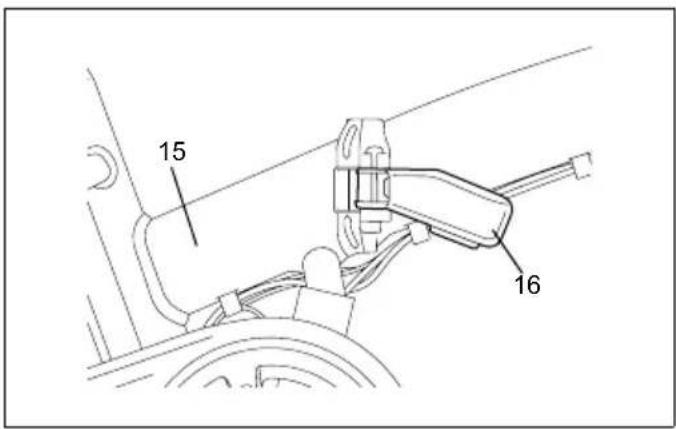
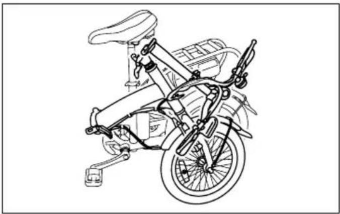
Stand on the left side of bicycle, and fold the handlebar stem first, then hold the frame with your left hand, hold the folding handle and move it to open.
Turn the folding handle as showed in Fig. 13. When the folding locking buckle is opened, then hold the frame from two sides and fold the frame toward the left of frame, and stop folding until the front wheel and rear wheel is parallel, as showed in Fig. 15 – 17.
Article 7. Accessories and adjustment
- The battery controller and motor cannot be removed.
- To change parts please come to the agency for change, we do not responsible for the problem which caused by customer who remove the parts by themselves.
- Please use the Makita battery BL1830 or BL1815.
- Brake adjustment.
Check the brake regularly and check as below: (Fig. 18 - 20)
4.1 Adjust front brake.
4.1.1. As shown in Fig. 18, check the front brake. The brake will be fully triggered when the brake lever is gripped to the half-closed position.
4.1.2. As shown in Fig. 19, loosen the screw to loosen or tighten the brake arms, and make the distance between the brake broad and the tire 1.5 – 2 mm. Tighten the screw. If the distance is different, please keep adjusting the spring until made the desired distance, is made which meets the 4.1.1 request.
4.2 Adjust the rear brake.
4.2.1. As shown in Fig. 18, check the rear brake as 4.1.1.
4.2.2. See Fig. 20, to adjust brake, as described in 4.1.1 showing adjustment of the front brake, loose the brake lever then adjust the screw till it touch the move board, enclasp the brake lever, adjust the move board and bolt (2 mm). Adjust some times till rearwheel turns well and brake function works well. When 1/3 of the brake is frayed, please change it.
Attention:
Please do not add lubricants on the rear brake. And please replace brake shoe in the front brake each year, to avoid shoe abrasion.
Brake maintenance
In order to maintain your bicycle's braking performance, it is important to perform maintenance on the braking system.
- Replacing brake cables and housings.
- Chain adjusting
Adjust as below:
Disassemble the plastic protecting cover of rear axle, and release two M12 nut. Turn the adjust nut
clockwise to make sure chain fixed well. During adjustment, if the chain is fixed too tight, please turn the nut counterclockwise and push the rear wheel forward.
If there are any parts needed to be adjusted, fix the screw and other parts tightly according to the requirements below. (Fig. 21)
| Parts Standardtwist | Remarks | |
| Locknut 14 – 18 N.m. The press sticker cannot show out | ||
| Stem 20 – 25 N.m. The safety line of stem cannot be seen | ||
| Seat screw 18 – 20 N.m. The safety line of seat post cannot be seen | ||
| Seat and fix the seat parts 18 – 22 N.m. | ||
| Hub 30 – 35 N.m. | ||
| Hub nut 35 – 40 N.m. | ||
| Pedal 18 – 20 N.m. | ||
| Handlebar 18 – 20 N.m. | ||
For European countries only
EC DECLARATION OF CONFORMITY
We Makita Corporation as the responsible
manufacturer declare that the following Makita
machine(s):
Designation of Machine:
Motor-assisted bicycle
Model No./ Type: BBY180
are of series production and
Conforms to the following European Directives:
2004/108/EC
And are manufactured in accordance with the following
standards or standardised documents:
EN55014-1: 2006, EN15194: 2009,
EN61000-3-2: 2006, EN61000-3-3: 2008,
EN55014-2/A2: 2008, IEC61000-4-2: 2008,
IEC61000-4-3: 2006, IEC61000-4-4: 2004,
IEC61000-4-5: 2005, IEC61000-4-6: 2006,
IEC61000-4-11: 2004
( The following standards are used for safety: EN14764: 2005, EN15194: 2009 )
The technical documentation is kept by our authorised representative in Europe who is:
Makita International Europe Ltd.,
Michigan, Drive, Tongwell,
Milton Keynes, Bucks MK15 8JD, England
-
- 2010

Tomoyasu Kato
Director
Makita Corporation
3-11-8, Sumiyoshi-cho,
Anjo, Aichi, 446-8502, JAPAN
Michigan, Drive, Tongwell,
Milton Keynes, Bucks MK15 8JD, Angleterre
15.7.2010

Tomoyasu Kato
Directeur
Makita Corporation
3-11-8, Sumiyoshi-cho,
Anjo, Aichi, 446-8502, JAPAN
IEC61000-4-3: 2006, IEC61000-4-4: 2004,
IEC61000-4-5: 2005, IEC61000-4-6: 2006,
IEC61000-4-11: 2004
Michigan, Drive, Tongwell,
Milton Keynes, Bucks MK15 8JD, England
15.7.2010

Tomoyasu Kato
Direktor
Makita Corporation
3-11-8, Sumiyoshi-cho,
Anjo, Aichi, 446-8502, JAPAN
Makita International Europe, Ltd., Michigan, Drive, Tongwell, Milton Keynes, Bucks MK15 8JD, Inghilterra
15.7.2010

IEC61000-4-3: 2006, IEC61000-4-4: 2004,
IEC61000-4-5: 2005, IEC61000-4-6: 2006,
IEC61000-4-11: 2004
Michigan Drive, Tongwell,
Milton Keynes, Bucks MK15 8JD, Engeland
15.7.2010

Tomoyasu Kato
Directeur
Makita Corporation
3-11-8, Sumiyoshi-cho,
Anjo, Aichi, 446-8502, JAPAN
IEC61000-4-3: 2006, IEC61000-4-4: 2004,
IEC61000-4-5: 2005, IEC61000-4-6: 2006,
IEC61000-4-11: 2004
Tomoyasu Kato Director
Makita Corporation
3-11-8, Sumiyoshi-cho, Anjo, Aichi, 446-8502, JAPAN
IEC61000-4-3: 2006, IEC61000-4-4: 2004,
IEC61000-4-5: 2005, IEC61000-4-6: 2006,
IEC61000-4-11: 2004
Michigan, Drive, Tongwell,
Milton Keynes, Bucks MK15 8JD, Inglaterra
15.7.2010
Tomoyasu Kato
Director
Makita Corporation
3-11-8, Sumiyoshi-cho,
Anjo, Aichi, 446-8502, JAPAN
IEC61000-4-3: 2006, IEC61000-4-4: 2004,
IEC61000-4-5: 2005, IEC61000-4-6: 2006,
IEC61000-4-11: 2004
Michigan, Drive, Tongwell,
Milton Keynes, Bucks MK15 8JD, England
15.7.2010
Tomoyasu Kato
Direktør
Makita Corporation
3-11-8, Sumiyoshi-cho,
Anjo, Aichi, 446-8502, JAPAN
IEC61000-4-3: 2006, IEC61000-4-4: 2004,
IEC61000-4-5: 2005, IEC61000-4-6: 2006,
IEC61000-4-11: 2004
Michigan, Drive, Tongwell,
Milton Keynes, Bucks MK15 8JD, England
15.7.2010

Tomoyasu Kato
Direktör
Makita Corporation
3-11-8, Sumiyoshi-cho,
Anjo, Aichi, 446-8502, JAPAN
IEC61000-4-3: 2006, IEC61000-4-4: 2004,
IEC61000-4-5: 2005, IEC61000-4-6: 2006,
IEC61000-4-11: 2004
Michigan, Drive, Tongwell,
Milton Keynes, Bucks MK15 8JD, England
15.7.2010

Tomoyasu Kato
Direktør
Makita Corporation
3-11-8, Sumiyoshi-cho,
Anjo, Aichi, 446-8502, JAPAN
IEC61000-4-3: 2006, IEC61000-4-4: 2004,
IEC61000-4-5: 2005, IEC61000-4-6: 2006,
IEC61000-4-11: 2004
Michigan, Drive, Tongwell,
Milton Keynes, Bucks MK15 8JD, England
15.7.2010
Tomoyasu Kato
Johtaja
Makita Corporation
3-11-8, Sumiyoshi-cho,
Anjo, Aichi, 446-8502, JAPAN
IEC61000-4-3: 2006, IEC61000-4-4: 2004,
IEC61000-4-5: 2005, IEC61000-4-6: 2006,
IEC61000-4-11: 2004
Michigan, Drive, Tongwell,
Milton Keynes, Bucks MK15 8JD, England
15.7.2010

Tomoyasu Kato
Διευθυντής
Makita Corporation
3-11-8, Sumiyoshi-cho,
Anjo, Aichi, 446-8502, JAPAN
DEKLARACJA ZGODNOŚCI WE
IEC61000-4-3: 2006, IEC61000-4-4: 2004,
IEC61000-4-5: 2005, IEC61000-4-6: 2006,
IEC61000-4-11: 2004
Michigan, Drive, Tongwell,
Milton Keynes, Bucks MK15 8JD, Wielka Brytania
15.7.2010

Tomoyasu Kato
Dyrektor
Makita Corporation
3-11-8, Sumiyoshi-cho,
Anjo, Aichi, 446-8502, JAPAN
IEC61000-4-3: 2006, IEC61000-4-4: 2004,
IEC61000-4-5: 2005, IEC61000-4-6: 2006,
IEC61000-4-11: 2004
Uz drošību attiecas šādi standarti:
EN14764: 2005, EN15194: 2009
Michigan, Drive, Tongwell
Milton Keynes, Bucks MK15 8JD, England
15.7.2010
Tomojasu Kato
Direktors
Makita Corporation
3-11-8, Sumiyoshi-cho,
Anjo, Aichi, 446-8502, JAPAN
IEC61000-4-3: 2006, IEC61000-4-4: 2004,
IEC61000-4-5: 2005, IEC61000-4-6: 2006,
IEC61000-4-11: 2004
Michigan, Drive, Tongwell,
Milton Keynes, Bucks MK15 8JD, Inglismaa
15.7.2010
Tomoyasu Kato
Direktor
Makita Corporation
3-11-8, Sumiyoshi-cho,
Anjo, Aichi, 446-8502, JAPAN
LIETUVIŲ KALBA (Originali instrukcija)
Bendrasis aprašymas
IEC61000-4-3: 2006, IEC61000-4-4: 2004,
IEC61000-4-5: 2005, IEC61000-4-6: 2006,
IEC61000-4-11: 2004
Michigan, Drive, Tongwell,
Milton Keynes, Bucks MK15 8JD, England (Anglija)
15.7.2010

Tomoyasu Kato
Direktorius
Makita Corporation
3-11-8, Sumiyoshi-cho,
Anjo, Aichi, 446-8502, JAPAN
IEC61000-4-3: 2006, IEC61000-4-4: 2004,
IEC61000-4-5: 2005, IEC61000-4-6: 2006,
IEC61000-4-11: 2004
Michigan, Drive, Tongwell,
Milton Keynes, Bucks MK15 8JD, Anglia.
15.7.2010

Tomoyasu Kato
Igazgató
Makita Corporation
3-11-8, Sumiyoshi-cho,
Anjo, Aichi, 446-8502, JAPAN
IEC61000-4-3: 2006, IEC61000-4-4: 2004,
IEC61000-4-5: 2005, IEC61000-4-6: 2006,
IEC61000-4-11: 2004
Michigan, Drive, Tongwell,
Milton Keynes, Bucks MK15 8JD, Anglia
15.7.2010

Tomoyasu Kato
Director
Makita Corporation
3-11-8, Sumiyoshi-cho,
Anjo, Aichi, 446-8502, JAPAN
DÔLEŽITÉ BEZPEČNOSTNÉ POKYNY
Pre akumulátor
IEC61000-4-3: 2006, IEC61000-4-4: 2004,
IEC61000-4-5: 2005, IEC61000-4-6: 2006,
IEC61000-4-11: 2004
Michigan, Drive, Tongwell,
Milton Keynes, Bucks MK15 8JD, Anglicko
15.7.2010
Tomoyasu Kato
Riaditel'
Makita Corporation
3-11-8, Sumiyoshi-cho,
Anjo, Aichi, 446-8502, JAPAN
TYTO POKYNY SI USCHOVEJTE.
IEC61000-4-3: 2006, IEC61000-4-4: 2004,
IEC61000-4-5: 2005, IEC61000-4-6: 2006,
IEC61000-4-11: 2004
Michigan, Drive, Tongwell,
Milton Keynes, MK15 8JD, England
15.7.2010

Tomoyasu Kato
Riaditel'
Makita Corporation
3-11-8, Sumiyoshi-cho,
Anjo, Aichi, 446-8502, JAPAN
IEC61000-4-3: 2006, IEC61000-4-4: 2004,
IEC61000-4-5: 2005, IEC61000-4-6: 2006,
IEC61000-4-11: 2004
Michigan, Drive, Tongwell,
Milton Keynes, Bucks MK15 8JD, Англія
15.7.2010
Томоязу Като
Директор
Makita Corporation
3-11-8, Sumiyoshi-cho,
Anjo, Aichi, 446-8502, JAPAN
IEC61000-4-3: 2006, IEC61000-4-4: 2004,
IEC61000-4-5: 2005, IEC61000-4-6: 2006,
IEC61000-4-11: 2004
Michigan, Drive, Tongwell,
Milton Keynes, Bucks MK15 8JD, England
15.7.2010

3-11-8, Sumiyoshi-cho,
Anjo, Aichi, 446-8502, JAPAN
Makita Corporation
Anjo, Aichi, Japan
BBY180_22L_0610
www.makita.com
- PLEASE READ CAREFULLY BEFORE USING BBY180
- FOR THE SAFETY USE, PLEASE LET OUR SALES STAFF ADJUST THE SEAT TO A COMFORTABLE POSITION
- CHECK BEFORE USE
- ATTENTION
- ARTICLE 1. TO THE CUSTOMER
- ARTICLE 2. INTRODUCTION OF BBY180
- TO SECURE YOUR SAFETY, PLEASE CHECK THE PRODUCT BEFORE USE
- BBY180
- OPERATION
- 3.1 HOW TO ADJUST YOUR POSITION ON THE BICYCLE
- ADJUST YOUR BICYCLE. (FIG. 2 - 3)
- WARNING
- ADJUSTING THE SEAT
- PRACTICAL INFORMATION
- 3.2 INTRODUCTION OF BATTERY: USE AND CARE FOR BBY180
- IMPORTANT SAFETY INSTRUCTIONS
- FOR BATTERY CARTRIDGE
- SAVE THESE INSTRUCTIONS
- TIPS FOR MAINTAINING A MAXIMUM BATTERY LIFE
- INSTRUCTION OF INSTALLING OR REMOVING BATTERY CARTRIDGE
- INSTALLING BATTERY CARTRIDGE
- NOTE
- REMOVING BATTERY CARTRIDGE
- 3.3 INSTRUCTION OF DISPLAY AND BUTTON (FIG. 8)
- ARTICLE 3. IMPORTANT NOTICE
- ARTICLE 4. CHARGING INSTRUCTION
- ARTICLE 5. REPAIR AND MAINTENANCE
- ARTICLE 6. USING INSTRUCTION FOR FOLDING PARTS
- ARTICLE 7. ACCESSORIES AND ADJUSTMENT
- BRAKE MAINTENANCE
- FOR EUROPEAN COUNTRIES ONLY
- EC DECLARATION OF CONFORMITY
- WE MAKITA CORPORATION AS THE RESPONSIBLE
- MANUFACTURER DECLARE THAT THE FOLLOWING MAKITA
- MACHINE(S)
- CONFORMS TO THE FOLLOWING EUROPEAN DIRECTIVES
- DEKLARACJA ZGODNOŚCI WE
- DÔLEŽITÉ BEZPEČNOSTNÉ POKYNY
- PRE AKUMULÁTOR
- TYTO POKYNY SI USCHOVEJTE
- MAKITA CORPORATION
Brand : MAKITA
Model : BBY180
Category : Electric bike