
DLE 70 - Rangefinder BOSCH - Free user manual and instructions
Find the device manual for free DLE 70 BOSCH in PDF.


| Product type | Laser distance meter |
| Brand | Bosch |
| Model | DLE 70 |
| Dimensions (L x W x H) | 105 x 47 x 25 mm |
| Weight | 110 g (with batteries) |
| Power supply | 2 AAA 1.5V batteries |
| Measuring range | 0.05 m to 70 m |
| Measurement accuracy | ± 1.5 mm |
| Main functions | Distance, area, volume measurement, continuous measurement, memory of 10 values |
| Measurement units | m, cm, ft, in |
| Display | Backlit LCD display |
| Laser class | 2, < 1 mW, 635 nm |
| Auto power-off | Yes, after 30 s (laser) / 5 min (unit) |
| Protection level | IP 54 (protected against water splashes and dust) |
| Operating temperature | -10 °C to +50 °C |
| Storage temperature | -20 °C to +70 °C |
| Package contents | DLE 70 distance measurer, protective case, 2 AAA batteries, user manual |
| Warranty | 2 years (extension possible under conditions) |
| Maintenance and cleaning | Wipe with a soft, dry cloth. Do not use solvents. |
| Safety | Do not look directly into the laser beam. Keep out of reach of children. |
| Spare parts and reparability | Standard AAA batteries available. Repair by Bosch authorized service center. |
Frequently Asked Questions - DLE 70 BOSCH
User questions about DLE 70 BOSCH
0 question about this device. Answer the ones you know or ask your own.
Ask a new question about this device
Download the instructions for your Rangefinder in PDF format for free! Find your manual DLE 70 - BOSCH and take your electronic device back in hand. On this page are published all the documents necessary for the use of your device. DLE 70 by BOSCH.
USER MANUAL DLE 70 BOSCH
OHJ BECH-703-002.book Page 1 Wednesday, July 23, 2008 7:21 PM
Robert Bosch GmbH
natural_image
Diagram showing a window with curtains and a camera emitting light rays from a screen (no text or symbols)
natural_image
Simple line drawing of a room with curtains and a hanging device (no text or symbols)


natural_image
Line drawing of a human face facing a device with visible ports and signal lines (no text or symbols)1 609 929 R53 | (23.7.08) Bosch Power Tools
BS 150
0 601 096 974
24
2 607 990 031

natural_image
Simple geometric diagram with a rectangle and vertical line, no text or symbols present25
2 607 001 391
27
1 609 203 X26
19
1 609 203 X36

natural_image
Isometric line drawing of a rectangular electronic component with mounting holes and a vertical line (no text or symbols)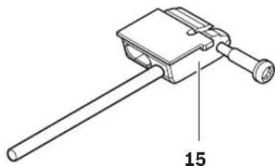
natural_image
Technical line drawing of a mechanical clamp or lever assembly (no text or symbols)1 609 203 X48
Deutsch | 7
Sicherheitshinweise

natural_image
Pure geometric diagram with crosshair and circular shapes (no text or symbols)12 | Deutsch
Working safely with the measuring tool is possible only when the operating and safety information are read completely and the instructions contained therein are strictly
followed. Never make warning labels on the measuring tool unrecognisable. SAVE THESE INSTRUCTIONS.
▶ Caution – The use of other operating or adjusting equipment or the application of other processing methods than those mentioned here, can lead to dangerous radiation exposure.
The measuring tool is delivered with a warning label in German language (marked with the number 9 in the representation of the measuring tool on the graphic page).

Before putting into operation for the first time, attach the supplied sticker in your national language over the German text on the warning label.
▶ Do not direct the laser beam at persons or animals and do not stare into the laser beam yourself. This measuring tool produces laser class 2 laser radiation according to IEC 60825-1. This can lead to persons being blinded.
▶ Do not use the laser viewing glasses as safety goggles. The laser viewing glasses are used for improved visualisation of the laser beam, but they do not protect against laser radiation.
Do not use the laser viewing glasses as sun glasses or in traffic. The laser viewing glasses do not afford complete UV protection and reduce colour perception.
▶ Have the measuring tool repaired only through qualified specialists using original spare parts. This ensures that the safety of the measuring tool is maintained.
Do not allow children to use the laser measuring tool without supervision. They could unintentionally blind other persons or themselves.
- Keep the positioning pin 15 away from "live" wires or parts. There is a risk of electric shock.
Functional Description
Please unfold the fold-out page with the representation of the measuring tool and leave it unfolded while reading the operating instructions.
Intended Use
The measuring tool is intended for measuring distances, lengths, heights, clearances and for calculating areas and volumes. The measuring tool is suitable for interior and exterior construction site measuring.
English | 19
Technical Data
| Digital Laser Rangefinder DLE 70 | |
| Professional | |
| Article number | 3 601 K16 60. |
| Measuring range | 0.05-70 m^A) |
| Measuring accuracy (typically) | ± 1.5 mm^B) |
| Lowest indication unit 1 m m | |
| Operating temperature | -10 ^...+50 ^ ^C) |
| Storage temperature -20 ^...+70 ^ | |
| Relative air humidity, max. | 90 % |
| Laser class | 2 |
| Laser type | 635 nm, <1 mW |
| Laser beam diameter (at 25 °C) approx.- at 10 m distance- at 70 m distance | 6 mm42 mm |
| Batteries | 4 x 1 . 5 V L R 0 3 ( A A A ) |
| Rechargeable batteries | 4 x 1 . 2 V K R 0 3 ( A A A ) |
| Battery live, approximately- Individual measurements- Continuous measurement | 30000^D) 5 h^D) |
| Automatic switch-off after approx.- Laser- Measuring tool (without measurement) | 20 s5 min |
| Weight according to EPTA-Procedure 01/2003 | 0.18 kg |
| Dimensions | 59 x 100 x 32 mm |
| Degree of protection (excluding battery compartment) | IP 54 (dust and splash water protected) |
A) The working range increases depending on how well the laser light is reflected from the surface of the target (scattered, not reflective) and with increased brightness of the laser point to the ambient light intensity (interior spaces, twilight). In unfavourable conditions (e.g. when measuring outdoors at intense sunlight), it may be necessary to use the target plate.
B) In unfavourable conditions (e.g. when measuring outdoors at intense sunlight or an insufficiently reflecting surface), the maximum deviation is ±10 mm per 70 m. In favourable conditions, a deviation influence of ±0.05 mm/m must be taken into account.
C) In the continuous measurement function, the maximum operating temperature is +40 °C.
D) Fewer measurements are possible when using 1.2 V rechargeable batteries as compared with 1.5 V batteries.
Please observe the article number on the type plate of your measuring tool. The trade names of the individual measuring tools may vary.
The measuring tool can be clearly identified with the serial number 20 on the type plate.


20 | English
Product Features
The numbering of the product features shown refers to the illustration of the measuring tool on the graphic page.
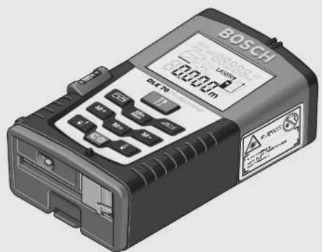
1 Reference level button
2 Memory retrieve button "M="
3 Memory add button "M+"
4 Button for minimum and maximum measurement
5 Button for length, area and volume measurement
6 Spirit level
7 Display
8 Alignment aid
9 Laser warning label
10 Button for measuring and continuous measuring
11 Button for indirect length measurement and measurement of wall surfaces
12 Memory subtraction button "M -"
13 Button for continuous laser beam
14 On/Off and memory delete button
15 Positioning pin
16 Latch of the positioning pin
17 1/4" thread
18 Latch of battery lid
19 Battery lid
20 Serial number
21 Laser beam outlet
22 Reception lens
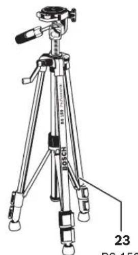
23 Tripod*
24 Laser viewing glasses*
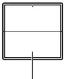
25 Laser target plate*
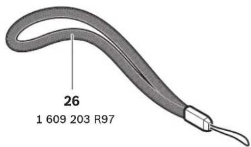
26 Carrying strap
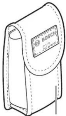
27 Protective case
*The accessories illustrated or described are not included as standard delivery.
Display Elements
a Measured values stored
b Battery indication
c Temperature indicator
d Measured value/result
e Unit of measure
f Measurement reference level
g Laser switched on
h Individual measured value (for length measurement: result)
i Measuring functions
— Length measurement
Area/surface measurement
Volume measurement
△ Indirect length measurement
Wall surface measurement
Continuous measurement
MIN Minimum measurement
MAX Maximum measurement
Assembly
Inserting/Replacing the Battery
Use only alkali-manganese or rechargeable batteries.
Fewer measurements are possible when using 1.2 V rechargeable batteries as compared with 1.5 V batteries.
To open the battery lid 19, press the latch 18 in the direction of the arrow and remove the battery lid. Insert the batteries provided. Pay attention to the correct polarity of the batteries according to the representation in the battery compartment.
When the battery symbol appears in the display for the first time, then at least 100 measurements are still possible. The batteries must be replaced when the battery symbol flashes; taking measurements is no longer possible.
Always replace all batteries at the same time. Only use batteries from one brand and with the identical capacity.
▶ Remove the batteries from the measuring tool when not using it for extended periods.
When storing for extended periods, the batteries can corrode and discharge themselves.




Operation
Initial Operation
▶ Protect the measuring tool against moisture and direct sun irradiation.
▶ Do not expose the measuring tool to extreme temperatures or variations in temperature.
Switching On and Off
To switch on the measuring tool, briefly press the On/Off button 14 or measuring button 10. When switching on the measuring tool, the laser beam is not switched on yet.
To switch off the measuring tool, press the On/Off button 14 for a few seconds.
If none of the measuring tool buttons are pressed for approx. 5 minutes, the measuring tool switches off automatically in order to extend the service life of the battery.
When a measured value has been stored, it is retained in automatic switch-off mode. When switching on the measuring tool again, "M" is indicated in the display.
Measuring Procedure
After switching on, the measuring tool is in the length measurement mode. Other measuring modes can be switched to by pressing the respective function/mode button (see "Measuring Functions", page 22).
After switching on, the rear edge of the measuring tool is preset as the reference level for the measurement. By pressing the reference level button 1, the reference level can be changed (see "Selecting the Reference Level", page 21). Upon selection of the measuring function and the reference level, all further steps are carried out by pushing the measuring button 10.
With the reference level selected, place the measuring tool against the desired measuring line (e.g. a wall).
Briefly press the measuring button 10 to switch on the laser beam.
▶ Do not point the laser beam at persons or animals and do not look into the laser beam yourself, not even from a large distance.
Aim the laser beam at the target surface. Briefly press the measuring button 10 again to initiate the measurement.
When the laser beam is switched on permanently and in the minimum and maximum measurement modes, the measurement already starts upon first actuation of the measuring button 10. In the continuous measurement mode, the measurement starts immediately upon switching on the function.
Typically, the measured value appears after 0.5 and latest after 4 seconds. The duration of the measurement depends on the distance, the light conditions and the reflection properties of the target surface. The end of the measurement is indicated by a signal tone. The laser beam is switched off automatically upon completion of the measurement.
When no measurement has taken place approx. 20 seconds after sighting, the laser beam is switched off automatically to save the batteries.
Selecting the Reference Level (see figures B–E)
For measuring, it is possible to select from four different reference levels:
- the rear edge of the measuring tool (e.g., when placing the measuring tool flush against a wall),
- the rear edge of the positioning pin 15 (e.g., for measurements out of corners).
- the front edge of the measuring tool (e.g., as when measuring from the edge of a table onward),
- the thread 17 (e.g., for measuring with the tripod).
To select the reference level, push button 1 repeatedly until the required reference level is indicated in the display. Each time after switching on, the rear edge of the measuring tool is preset as the reference level.



22 | English
Continuous Laser Beam
If required, the measuring tool can also be switched to the continuous laser beam mode. For this, push the button for continuous laser beam
- "LASER" lights up continuously in the display.
▶ Do not point the laser beam at persons or animals and do not look into the laser beam yourself, not even from a large distance.
In this setting, the laser beam also remains switched on between measurements; for measuring, it is only required to press the measuring button 10 once.
To switch off the continuous laser beam, press button 13 again or switch the measuring tool off. When switching on again, the measuring tool is in the standard operation mode and the laser beam appears only after pushing the measuring button 10.
Measuring Functions
Length Measurement
For length measurements, press button 5 until the indicator for length measurement – appears in the display.

Press the measuring button 10 once for sighting and once more to take the measurement.
The measured value is indicated at the bottom in the display.
Area Measurement
For area/surface measurements, press button 5 until the indicator for area measurement □ appears in the display.
Afterwards, measure the length and the width, one after another, in the same manner as a length measurement. The laser beam remains switched on between both measurements.

After taking the second measurement, the area/ surface is automatically calculated and displayed. The last individual measured value is indicated at
the bottom in the display, while the final result is shown at the top.
Volume Measurement
For volume measurements, press button 5 until the indicator for volume measurement 📋 appears in the display.
Afterwards, measure the length, width and the height, one after another, in the same manner as for a length measurement. The laser beam remains switched on between all three measurements.

After taking the third measurement, the volume is automatically calculated and displayed. The last individual measured value is indicated at the bottom in the display, while the final result is shown at the top.
Values above 99999 m ^3 cannot be indicated; "Error" and "----" appear on the display. Divide the volume to be measured into individual measurements; their values can then be calculated separately and then summarized.
Minimum Measurement (see figure F)
The minimum measurement is used to determine the shortest distance from a fixed reference point. It is used, as an example, for determining plumb lines or horizontal partitions.
For minimum measurements, press button 4 until "MIN" appears in the display.
To start the measurement, briefly press the measuring button 10.
Move the laser back and forth over the requested target (e.g., the room ceiling for determining the plumb line) in such a manner that the reference point of the measurement (e.g., the tip of the positioning pin 15) always remains at the same location.

During the measurement, the current length measurement value is indicated at the bottom of the display. The minimum value is indicated at the top right in
the display. It is always overwritten, when the current length measurement value is lower than the present minimal value.
To end the minimum measurement, briefly press the measuring button 10. Pressing the measuring button again starts a new measurement.




Maximum Measurement (see figure G)
The maximum measurement is used to determine the greatest distance from a fixed reference point. It is used, as an example, for determining diagonals.
For maximum measurements, press button 4 until "MAX" appears in the display.
To start the measurement, briefly press the measuring button 10.
Move the laser back and forth over the requested target (e.g., the room corner for determining the diagonal) in such a manner that the reference point of the measurement (e.g., the tip of the positioning pin 15) always remains at the same location.

During the measurement, the current length measurement value is indicated at the bottom of the display. The minimum value is indicated at the top right in
the display. It is always overwritten, when the current length measurement value is larger than the present maximal value.
To end the maximum measurement, briefly press the measuring button 10. Pressing the measuring button again starts a new measurement.
Indirect Length Measurement (see figure H)
The indirect length measurement is used to measure distances that cannot be measured directly because an obstacle would obstruct the laser beam or no target surface is available as a reflector. Correct results are achieved only when the laser beam and the sought distance form an exact right angle (Pythagorean Theorem).
In the illustrated example, the length B is to be determined. For this purpose, A and C must be measured. A and B must form a right angle.
For indirect length measurements, press button 11 until the indicator for indirect length measurement appears in the display.
Measure the distance A as for a length measurement. Pay attention that the line segment A and the sought distance B form a right angle.
Afterwards, measure the distance C. The laser beam remains switched on between both measurements.
Pay attention that the reference point of the measurement (e.g., the rear edge of the measuring tool) is at the exact same location for both measurements.
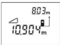
After completing the second measurement, the distance B is calculated automatically. The last individual measured value is indicated at the bottom in the display, while the final result B is indicated at the top.
Wall Surface Measurement (see figure I)
The wall surface measurement is used to determine the sum of several individual surfaces with a common length.
In the example shown, the total surface of several walls that have the same room height A, but different lengths B, are to be determined.
For wall surface measurements, press button 11 until the indicator for wall surface measurement appears in the display.
Measure the room height A as for a length measurement. The measured value is indicated both at the top and bottom in the display. The laser remains switched on.
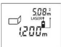
Afterwards, measure length B_1 of the first wall. The surface is automatically calculated and indicated. The last length measurement value is indicated at the
bottom in the display, while the surface is indicated at the top. The laser remains switched on.

Now, measure length B_2 of the second wall. The individual measuring value indicated at the bottom of the display is added to length B_1 and the sum of
both lengths is multiplied with the stored length A. The total surface value is indicated at the top in the display.
In this manner, you can measure any number of further lengths B_x , which are added and multiplied with length A.



24 | English
The condition for a correct area/surface calculation is that the first measured length (in the example the room height A) is identical for all partial surfaces.
To restart the wall surface measurement, press button 11 twice.
Continuous Measurement (Tracking) (see figure J)
The continuous measurement function (tracking) is used for the transferring of measurements, e.g., from construction plans. In continuous measurement mode, the measuring tool can be moved relative to the target, whereby the measured value is updated approx. every 0.5 seconds. As an example, the user can move from a wall to the required distance, while the actual distance can be read continuously.
For continuous measurements, first select the length measuring function and then press button 10 until the indicator for continuous measurement--appears on the display. The laser is switched on and the measurement starts immediately.

Move the measuring tool until the required distance value is indicated in the bottom of the display.
Briefly pressing button 10 ends the continuous measurement. The last meas-
ured value is indicated at the bottom in the display. Pressing button 10 for several seconds restarts a continuous measuring run.
The continuous measuring automatically switches off after 5 min. The last measured value remains indicated in the display.
Deleting Measured Values
Briefly pressing button 14 deletes the last individual measuring value determined in all measuring functions. Briefly pressing the button repeatedly deletes the individual measured values in reverse order.
In the wall surface measurement mode, briefly pressing button 14 the first time deletes the last individually measured value; pressing the button a second time deletes all lengths B_x .
Memory Functions
When switching off the measuring tool, the value in the memory is retained.
In the wall surface measurement mode, the total surface value can be stored; in the minimum and maximum measuring mode, the minimum and maximum value can be stored correspondingly. Storing individual measuring values within these functions is not possible.
Storing/Adding Measured Values

Push the memory add button 3 in order to store the current measured value – a length, area or volume value, depending on the current measuring function.
As soon as a value has been stored, "M" is indicated in the display and the "+" behind it briefly flashes.
If a value is already stored in the memory, the new value is added to the memory contents, however, only when the measures of unit correspond.
As an example, when an area value is in the memory and the current measured value is a volume value, the addition cannot take place.
"Error" briefly flashes in the display.
Subtracting Measured Values
Push the memory subtraction button 12 in order to subtract the current measured value from the memory value. As soon as a value has been subtracted, "M" is indicated in the display and the "-" behind it briefly flashes.
If a value is already stored in the memory, the new measured value can be subtracted only when the measures of unit correspond (see "Storing/Adding Measured Values").
Displaying the Stored Value
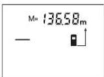
Push the memory retrieve button 2 in order to display the value stored in the memory. "M=" is indicated in the display. When the memory contents "M=" is
indicated in the display, it can be doubled by pushing the memory add button 3 or set to zero by pushing the memory subtract button 12.
Deleting the Memory
To delete the memory contents, first push the memory retrieve button 2, so that "M=" is indicated in the display. Then briefly press button 14; "M" is no longer indicated in the display.
Working Advice
General Information
The reception lens 22 and the laser beam outlet 21 must not be covered when taking a measurement.
The measuring tool must not be moved while taking a measurement (with the exception of the continuous measurement function and the minimum/maximum measurement). Therefore, place the measuring tool, as far as this is possible, against or on the measuring points.
Measurement takes place at the centre of the laser beam, even when target surfaces are sighted at an incline.
Influence Effects on the Measuring Range
The measuring range depends upon the light conditions and the reflection properties of the target surface. For improved visibility of the laser beam when working outdoors and when the sunlight is intense, use the laser viewing glasses 24 (accessory) and the laser target plate 25 (accessory), or shade off the target surface.
Influence Effects on the Measuring Result
Due to physical effects, faulty measurements cannot be excluded when measuring on different surfaces. Included here are:
- Transparent surfaces (e.g., glass, water),
- Reflecting surfaces (e.g., polished metal, glass),
- Porous surfaces (e.g. insulation materials),
- Structured surfaces (e.g., roughcast, natural stone).
If required, use the laser target plate 25 (accessory) on these surfaces.
Also, air layers with varying temperatures or indirectly received reflections can affect the measured value.
Measuring with the Positioning Pin (see figures C, F and G)
The positioning pin 15 is suitable for measuring out of corners (diagonal within a space) or from hard to reach areas, such as from roller-shutter rails.
Slide the latch 16 of the positioning pin sideward in order to swivel out the pin.
Set the corresponding reference level for measurements with the positioning pin by pushing button 1.
The positioning pin 15 swivels back in again by pushing it toward the housing to the stop. The pin automatically locks in place.
Aligning with the Spirit Level
The spirit level 6 allows for simple levelling of the measuring tool. This allows for easier sighting of target surfaces, especially over longer distances. In combination with the laser beam, the spirit level 6 is not suitable for levelling.
Sighting with the Alingment Aid (see figure K)
With the alignment aid 8, sighting over larger distances is a lot easier. For this, look alongside the aligning aid on the top side of the measuring tool. The laser beam runs parallel to this line of sight.
Working with the Tripod (Accessory)
The use of a tripod is particularly necessary for larger distances. Position the measuring tool with the 1/4" thread 17 onto the quick-change plate of the tripod 23 or a commercially available camera tripod. Tighten the measuring tool with the locking screw of the quick-change plate.
Set the corresponding reference level for measurement with a tripod by pushing button 1 (the reference level is the thread).






26 | English
Troubleshooting - Causes and Corrective Measures
Cause Corrective
Measure
Temperature indicator (c) flashes; measurement not possible
| The measuring tool is outside the operating temperature range from -10 ^ to +50 ^ (in the function continuous measurement up to +40 ^ ). | Wait until the measuring tool has reached the operating temperature |
Battery indication (b) is indicated
| Battery voltage decreasing (measurement still possible) | Replace batteries |
Battery indication (b) flashes, measurement not possible
Battery voltage too low Replace batteries
"Error" and "----" indication in display
| The angle between the laser beam and the target is too acute. | Enlargen the angle between the laser beam and the target |
| The target surface reflects too intensely (e.g. a mirror) or insufficiently (e.g. black fabric), or the ambient light is too bright. | Work with the laser target plate 25 (accessory) |
| The laser beam outlet 21 or the reception lens 22 are misted up (e.g. due to a rapid temperature change). | Wipe the laser beam outlet 21 and/or the reception lens 22 dry using a soft cloth |
| Calculated value is greater than 99999 m/m2/m3. | Divide calculation into intermediate steps |
"Error" indication flashes at in display (top)
| Addition/Subtraction of measured values with different units of measure | Only add/subtract measured values with the same units of measure |
Cause Corrective
Measure
Unreliable measuring result
| The target surface does not reflect correctly (e.g. water, glass). | Cover off the target surface |
| The laser beam outlet 21 or the reception lens 22 are covered. | Make sure that the laser beam outlet 21 or the recep- |
Measuring result not plausible
| Wrong reference level set | Select reference level that corresponds to measurement |
| Obstruction in path of laser beam | Laser point must be completely on target surface. |

The measuring tool monitors the correct function for each measurement. When a defect is determined, only the symbol shown aside flashes in the display. In this case, or when the above men-
tioned corrective measures cannot correct an error, have the measuring tool checked by an after-sales service agent for Bosch power tools.
Accuracy Check of the Measuring Tool
The accuracy of the measuring tool can be checked as follows:
- Select a permanently unchangeable measuring section with a length of approx. 3 to 10 metres; its length must be precisely known (e.g. the width of a room or a door opening). The measuring distance must be indoors; the target surface for the measurement must be smooth and reflect well.
- Measure the distance 10 times after another.
The measuring error must not amount to more than a maximum of ± 2.0 mm. Keep a record of the measurements in order to compare the accuracy at a later time.
Maintenance and Service
Maintenance and Cleaning
Store and transport the measuring tool only in the supplied protective case.
Keep the measuring tool clean at all times.
Do not immerse the measuring tool into water or other fluids.
Wipe off debris using a moist and soft cloth. Do not use any cleaning agents or solvents.
Maintain the reception lens 22 in particular, with the same care as required for eye glasses or the lens of a camera.
If the measuring tool should fail despite the care taken in manufacturing and testing procedures, repair should be carried out by an authorized after-sales service centre for Bosch power tools.
In all correspondence and spare parts orders, please always include the 10-digit article number given on the type plate of the measuring tool.
In case of repairs, send in the measuring tool packed in its protective case 27.
Accessories/Spare Parts
Accessories
Construction tripod BS 150 23 .... 0 601 096 974
Laser viewing glasses 24 ..... 2 607 990 031
Laser target plate 25 ..... 2 607 001 391
Spare Parts
Carrying strap 26....1 609 203 R97
Protective case 27 ..... 1 609 203 X26
Battery lid 19....1 609 203 X36
Positioning pin 15....1 609 203 X48
After-sales Service and Customer Assistance
Our after-sales service responds to your questions concerning maintenance and repair of your product as well as spare parts. Exploded views and information on spare parts can also be found under:
www.bosch-pt.com
Our customer consultants answer your questions concerning best buy, application and adjustment of products and accessories.
Great Britain
Robert Bosch Ltd. (B.S.C.)
P.O. Box 98
Broadwater Park
North Orbital Road
Denham
Uxbridge
UB 9 5HJ
Tel. Service: +44 (0844) 736 0109
Fax: +44 (0844) 736 0146
Australia, New Zealand and Pacific Islands
Robert Bosch Australia Pty. Ltd.
Power Tools
Locked Bag 66
Clayton South VIC 3169
Customer Contact Center
Inside Australia:
Phone: +61 (01300) 307 044
Fax: +61 (01300) 307 045
Inside New Zealand:
Phone: +64 (0800) 543 353
Fax: +64 (0800) 428 570
Outside AU and NZ:
Phone: +61 (03) 9541 5555
www.bosch.com.au
28 | English
People's Republic of China
Website: www.bosch-pt.com.cn
China Mainland
Bosch Power Tools (China) Co., Ltd.
567, Bin Kang Road
Bin Jiang District 310052
Hangzhou, P.R.China
Service Hotline: 800 8 20 84 84
Tel.: +86 (571) 87 77 43 38
Fax: +86 (571) 87 77 45 02
HK and Macau Special Administrative Regions
Robert Bosch Hong Kong Co. Ltd.
21st Floor, 625 King's Road
North Point, Hong Kong
Customer Service Hotline: +852 (21) 02 02 35
Fax: +852 (25) 90 97 62
E-Mail: info@hk.bosch.com
www.bosch-pt.com.cn
Indonesia
PT. Multi Tehaka
Kawasan Industri Pulogadung
Jalan Rawa Gelam III No. 2
Jakarta 13930
Indonesia
Tel.: +62 (21) 4 60 12 28
Fax: +62 (21) 46 82 68 23
E-Mail: sales@multitehaka.co.id
www.multitehaka.co.id
Phillippines
Robert Bosch, Inc.
Zuellig Building
Sen. Gil Puyat Avenue
Makati City 1200, Metro Manila
Philippines
Tel.: +63 (2) 8 17 32 31
www.bosch.com.ph
Malaysia
Robert Bosch (SEA.) Pte. Ltd.
No. 8a, Jalan 13/6
46200 Petaling Jaya,
Selangor,
Malaysia
Tel.: +6 (03) 7966 3000
Fax: +6 (03) 7958 3838
E-Mail: hengsiang.yu@my.bosch.com
Toll Free Tel.: 1 800 880 188
Fax: +6 (03) 7958 3838
www.bosch.com.sg
Thailand
Robert Bosch Ltd.
Liberty Square Building
No. 287, 11 Floor
Silom Road, Bangrak
Bangkok 10500
Tel.: +66 (2) 6 31 18 79 - 18 88 (10 lines)
Fax: +66 (2) 2 38 47 83
Robert Bosch Ltd., P. O. Box 2054
Bangkok 10501, Thailand
Bosch Service – Training Centre
2869-2869/1 Soi Ban Kluay
Rama IV Road (near old Paknam Railway)
Prakanong District
10110 Bangkok
Thailand
Tel.: +66 (2) 6 71 78 00 - 4
Fax: +66 (2) 2 49 42 96
Fax: +66 (2) 2 49 52 99
Singapore
Robert Bosch (SEA.) Pte. Ltd.
38 C Jalan Pemimpin
Singapore 915701
Republic of Singapore
Tel.: +65 (3) 50 54 94
Fax: +65 (3) 50 53 27
www.bosch.com.sg
Vietnam
Robert Bosch (SEA) Pte. Ltd - Vietnam
Representative Office
Saigon Trade Center, Suite 1206
37 Ton Duc Thang Street,
Ben Nghe Ward, District 1
HCMC
Vietnam
Tel.: +84 (8) 9111 374 - 9111 375
Fax: +84 (8) 9111376
Disposal
Measuring tools, accessories and packaging should be sorted for environmental-friendly recycling.
Only for EC countries:

Do not dispose of measuring tools into household waste!
According the European Guideline 2002/96/EC for Waste Electrical and Electronic Equipment and its implementation into national
right, measuring tools that are no longer usable must be collected separately and disposed of in an environmentally correct manner.
Battery packs/batteries:
Do not dispose of battery packs/batteries into household waste, fire or water. Battery packs/batteries should be collected, recycled or disposed of in an environmental-friendly manner.
Only for EC countries:
Defective or dead out battery packs/batteries must be recycled according the guideline 91/157/EEC.
Batteries no longer suitable for use can be directly returned at:
Great Britain
Robert Bosch Ltd. (B.S.C.)
P.O. Box 98
Broadwater Park
North Orbital Road
Denham
Uxbridge
UB 9 5HJ
Tel. Service: +44 (0844) 736 0109
Fax: +44 (0844) 736 0146
Subject to change without notice.




30 | Français
natural_image
Pure geometric diagram with crosshair and circular shapes (no text or symbols)36 | Français
Robert Bosch (France) S.A.S.
OBJ BUCH-703-002.book Page 62 Wednesday, July 23, 2008 3:15 PM

natural_image
Pure geometric crosshair symbol with concentric circles and lines, no text or labels present62 | Português
Eliminação
natural_image
Pure geometric diagram with crosshair and circular shapes (no text or symbols)68 | Italiano
natural_image
Pure geometric diagram with crosshair and circular shapes, no text or symbols present70 | Italiano
Funzioni di memoria
natural_image
Pure geometric diagram with crosshair and circular shapes (no text or symbols)80 | Nederlands
natural_image
Pure geometric diagram with crosshair and circle shapes without any text or symbolsAfvalverwijdering
Bosch Service Center
Telegrafvej 3
2750 Ballerup
Tel. Service Center: +45 (04489) 8855
Fax: +45 (04489) 87 55
E-Mail: vaerktoej@dk.bosch.com
Bortskaffelse
Bosch Service Center
Telegrafvej 3
2750 Ballerup
Danmark
Tel.: +46 (020) 41 44 55
Fax: +46 (011) 18 76 91
Avfallshantering
Bosch San. ve Tic. A.S.
Ahi Evran Cad. No:1 Kat:22
Polaris Plaza
80670 Maslak/Istanbul
Bosch Service Center PT
K Vápence 1621/16
692 01 Mikulov
Tel.: +420 (519) 305 700
Fax: +420 (519) 305 705
E-Mail: servis.naradi@cz.bosch.com
www.bosch.cz
Zpracování odpadů
OBJ BUCH-703-002.book Page 178 Wednesday, July 23, 2008 3:15 PM

natural_image
Pure geometric diagram with crosshair and circular shapes (no text or symbols)178 | Slovensky
Likvidácia
Bosch Service Center
Str. Horia Măcelariu Nr. 30-34,
013937 Bucureşti
Tel. Service scule electrice: +40 (021) 4 05 75 40
Fax: +40 (021) 4 05 75 66
E-Mail: infoBSC@ro.bosch.com
Robert Bosch Korea Mechanics and Electronics Ltd.
전동공구 사업부


- Sicherheitshinweise
- | Deutsch
- Functional Description
- Intended Use
- | English
- Product Features
- Display Elements
- Assembly
- Inserting/Replacing the Battery
- Operation
- Initial Operation
- Switching On and Off
- Measuring Procedure
- Selecting the Reference Level (see figures B–E)
- | English
- Continuous Laser Beam
- Measuring Functions
- Length Measurement
- Area Measurement
- Volume Measurement
- Minimum Measurement (see figure F)
- Maximum Measurement (see figure G)
- Indirect Length Measurement (see figure H)
- Wall Surface Measurement (see figure I)
- | English
- Continuous Measurement (Tracking) (see figure J)
- Deleting Measured Values
- Memory Functions
- Storing/Adding Measured Values
- Subtracting Measured Values
- Displaying the Stored Value
- Deleting the Memory
- Working Advice
- General Information
- Influence Effects on the Measuring Range
- Influence Effects on the Measuring Result
- Measuring with the Positioning Pin (see figures C, F and G)
- Aligning with the Spirit Level
- Sighting with the Alingment Aid (see figure K)
- Working with the Tripod (Accessory)
- Troubleshooting - Causes and Corrective Measures
- Cause Corrective
- Measure
- Temperature indicator (c) flashes; measurement not possible
- Battery indication (b) flashes, measurement not possible
- "Error" and "----" indication in display
- "Error" indication flashes at in display (top)
- Unreliable measuring result
- Measuring result not plausible
- Accuracy Check of the Measuring Tool
- Maintenance and Service
- Maintenance and Cleaning
- Accessories/Spare Parts
- Accessories
- Spare Parts
- After-sales Service and Customer Assistance
- www.bosch-pt.com
- Great Britain
- Australia, New Zealand and Pacific Islands
- | English
- People's Republic of China
- China Mainland
- HK and Macau Special Administrative Regions
- Indonesia
- Phillippines
- Malaysia
- Thailand
- Singapore
- Vietnam
- Disposal
- Only for EC countries:
- Battery packs/batteries:
- | Français
- | Français
- | Português
- Eliminação
- | Italiano
- | Italiano
- Funzioni di memoria
- | Nederlands
- Afvalverwijdering
- Bortskaffelse
- Avfallshantering
- Zpracování odpadů
- | Slovensky
- Likvidácia
- 전동공구 사업부
Brand : BOSCH
Model : DLE 70
Category : Rangefinder