
GLL 2-50 Professional - Rangefinder BOSCH - Free user manual and instructions
Find the device manual for free GLL 2-50 Professional BOSCH in PDF.

 FR
FR
 BG
BG
 CS
CS
 DA
DA
 DE
DE
 EL
EL
 EN
EN
 ES
ES
 ET
ET
 FI
FI
 HU
HU
 ID
ID
 IT
IT
 KK
KK
 KO
KO
 LT
LT
 LV
LV
 MK
MK
 NL
NL
 NO
NO
 PL
PL
 PT
PT
 RO
RO
 RU
RU
 SK
SK
 SL
SL
 SV
SV
 TR
TR
 UK
UK
 VI
VI
 ZH
ZH
| Product type | Cross-line laser rangefinder |
| Brand | Bosch |
| Model | GLL 2-50 Professional |
| Dimensions (L x W x H) | 120 x 65 x 115 mm |
| Weight | 0.35 kg (with batteries) |
| Power supply | 2 AA batteries (1.5 V) |
| Measuring range | Up to 50 m (with receiver) |
| Leveling accuracy | ± 0.3 mm/m |
| Self-leveling | Yes, leveling range ± 4° |
| Number of beams | 2 cross lines (horizontal and vertical) |
| Laser class | Class 2 (635 nm, < 1 mW) |
| Main functions | Distance measurement, leveling, line tracing |
| Maintenance and cleaning | Clean with a soft, dry cloth, avoid solvents |
| Safety | Do not look directly into the laser beam |
| Spare parts and repairability | User-replaceable batteries; repair by Bosch authorized service center |
| General information | Indoor and outdoor use (with receiver) |
Frequently Asked Questions - GLL 2-50 Professional BOSCH
User questions about GLL 2-50 Professional BOSCH
0 question about this device. Answer the ones you know or ask your own.
Ask a new question about this device
Download the instructions for your Rangefinder in PDF format for free! Find your manual GLL 2-50 Professional - BOSCH and take your electronic device back in hand. On this page are published all the documents necessary for the use of your device. GLL 2-50 Professional by BOSCH.
USER MANUAL GLL 2-50 Professional BOSCH
ORI BUCH-817-007.hook Page 1 Monday, July 4, 2016 6:34 PM
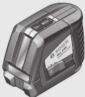
natural_image
3D rendered image of a Bosch industrial sensor device (no visible text or symbols on body)Robert Bosch Power Tools GmbH
70538 Stuttgart
GERMANY
www.bosch-pt.com
1609 92A 27R (2016.04) T/223

1609 92A 27R
GLL 2-50 Professional

BOSCH
by Comitivat, MIGRACCH
mk. Сривынсько-кредствам за рабета
sr Originaln unulstvo za rad
sllvina nssunile
hr Originalne upute za rad
natural_image
Interior view of a room with ceiling-mounted equipment and a vertical pole (no text or symbols visible)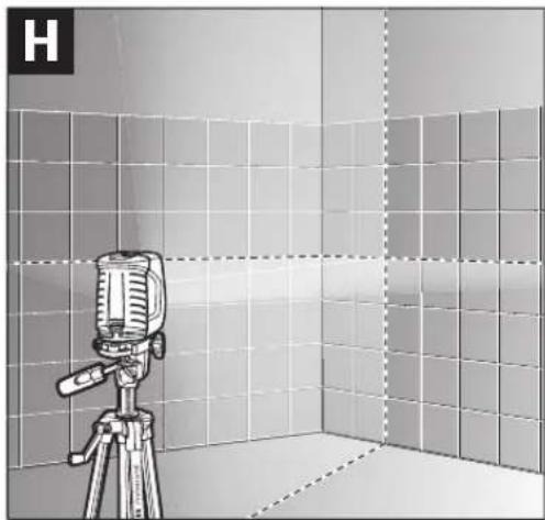
natural_image
Illustration of a vintage camera on a tripod in a tiled room, no text or symbols present
natural_image
Diagram of a camera setup in a room with shelves and walls, showing alignment lines (no text or symbols)
natural_image
Interior corner view of a room with tiled floor and wall-mounted device, no visible text or symbols

6 | Deutsch
Deutsch
Sicherheitshinweise

All instructions must be read and observed in order to work safely with the measuring tool. The integrated protections in the measuring tool may be compromised if the measuring tool is not used in accordance
with the instructions provided. Never make warning signs on the measuring tool unrecognisable. STORE THESE INSTRUCTIONS IN A SAFE PLACE AND INCLUDE THEM WITH THE MEASURING TOOL WHEN GIVING IT TO A THIRD PARTY.
▶ Caution – The use of other operating or adjusting equipment or the application of other processing methods than those mentioned here can lead to dangerous radiation exposure.
The measuring tool is provided with a warning label (marked with number 10 in the representation of the measuring tool on the graphics page).
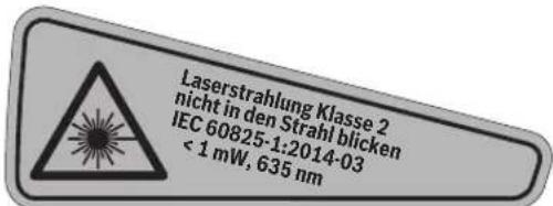
▶ If the text of the warning label is not in your national language, stick the provided warning label in your national language over it before operating for the first time.

Do not direct the laser beam at persons or animals and do not stare into the direct or reflected laser beam yourself, not even from a distance. You could blind somebody, cause accidents or damage your eyes.
▶ If laser radiation strikes your eye, you must deliberately close your eyes and immediately turn your head away from the beam.
▶ Do not make any modifications to the laser equipment.
▶ Do not use the laser viewing glasses as safety goggles. The laser viewing glasses are used for improved visualisation of the laser beam, but they do not protect against laser radiation.
Do not use the laser viewing glasses as sun glasses or in traffic. The laser viewing glasses do not afford complete UV protection and reduce colour perception.
▶ Have the measuring tool repaired only through qualified specialists using original spare parts. This ensures that the safety of the measuring tool is maintained.
▶ Do not allow children to use the laser measuring tool without supervision. They could unintentionally blind other persons or themselves.
Do not operate the measuring tool in explosive environments, such as in the presence of flammable liquids, gases or dusts. Sparks can be created in the measuring tool which may ignite the dust or fumes.

Keep the measuring tool away from cardiac pacemakers. The magnet inside the measuring tool generates a field that can impair the function of cardiac pacemakers.
- Keep the measuring tool away from magnetic data media and magnetically-sensitive equipment. The effect of the magnet can lead to irreversible data loss.
Product Description and Specifications
Please unfold the fold-out page with the representation of the measuring tool and leave it unfolded while reading the operating instructions.
Intended Use
The measuring tool is intended for determining and checking horizontal and vertical lines.
Technical Data
Cross-line Laser GLL2-50
| Article number | 3601K631. |
| Working range | |
| - Standard | 20 m |
| - With pulse function | 15 m |
| - With laser receiver | 50 m |
| Levelling Accuracy | ±0.3 mm/m |
| Self-levelling range, typically | ±4° |
| Levelling duration, typically | <4 s |
| Operating temperature | -10°C...+50°C |
| Storage temperature | -20°C...+70°C |
| Relative air humidity, max. | 90 % |
| Laser class | 2 |
| Laser type | 635 nm,<1 mW |
| C_B | 1 |
The measuring tool can be clearly identified with the serial number 9 on the type plate.





English | 13
Cross-line Laser GLL2-50
| Shortest pulse duration | 1/1600 s |
| Divergence of laser line | 0.5 mrad (full angle) |
| Tripod mount | 1/4" |
| Batteries | 3 x 1 . 5 V L R 6 (A A) |
| Operating time, approx. | 12 h |
| Automatic switch-off after approx. | 30 min |
| Weight according to EPTA-Procedure 01:2014 | 0.45 kg |
| Dimensions | 118 x 57 x 89 mm |
| Degree of protection | IP 54 (dust and splash water protected) |
The measuring tool can be clearly identified with the serial number 9 on the type plate.
Product Features
The numbering of the product features shown refers to the illustration of the measuring tool on the graphic page.
1 Exit opening for laser beam
2 Pulse-function indicator
3 Pulse-function button
4 Operating mode button
5 Battery indicator
6 Tripod mount 1/4"
7 On/Off switch
8 Battery lid
9 Serial number
10 Laser warning label
11 Latch of battery lid
12 Alignment plate*
13 0° alignment aid on the alignment plate
14 90° alignment aid on the alignment plate
15 45° alignment aid on the alignment plate
16 Pin on the alignment plate
17 Protective pouch*
18 Case*
19 Laser viewing glasses*
20 Measuring plate with stand*
21 Laser receiver*
* The accessories illustrated or described are not included as standard delivery.
Assembly
Inserting/Replacing the Batteries
Use only alkali-manganese batteries.
To open the battery lid 8, press the latch of the battery lid 11 in the direction of the arrow and remove the battery lid. Insert the supplied batteries. When inserting, pay attention to the correct polarity according to the representation on the inside of the battery compartment.
When the battery indication 5 flashes red, the batteries must be replaced.
Always replace all batteries at the same time. Only use batteries from one brand and with the identical capacity.
Remove the batteries from the measuring tool when not using it for extended periods. When storing for extended periods, the batteries can corrode and self-discharge.
Operation
Initial Operation
▶ Protect the measuring tool against moisture and direct sun light.
Do not subject the measuring tool to extreme temperatures or variations in temperature. As an example, do not leave it in vehicles for a long time. In case of large variations in temperature, allow the measuring tool to adjust to the ambient temperature before putting it into operation. In case of extreme temperatures or variations in temperature, the accuracy of the measuring tool can be impaired.
- Avoid heavy impact or falling of the measuring tool. After heavy exterior impact on the measuring tool, an accuracy check should always be carried out before continuing to work (see "Levelling Accuracy").
▶ Switch the measuring tool off during transport. When switching off, the levelling unit, which can be damaged in case of intense movement, is locked.
Switching On and Off
To switch on the measuring tool, slide the On/Off switch 7 to the “○ o n ” position (when working without automatic levelling) or to the “○ on” position (when working with automatic levelling). Immediately after switching on, the measuring tool sends laser beams out of the exit openings 1.
▶ Do not point the laser beam at persons or animals and do not look into the laser beam yourself, not even from a large distance.
To switch off the measuring tool, slide the On/Off switch 7 to the "off" position. When switching off, the levelling unit is locked.
Deactivating the Automatic Shut-off
The measuring tool switches off automatically after an operating duration of 30 minutes. To deactivate the automatic switch-off, keep the operating mode button 4 pressed for 3 s while switching on the measuring tool. When the automatic switch-off is deactivated, the laser lines briefly flash after 3 s.
▶ Do not leave the switched-on measuring tool unattended and switch the measuring tool off after use. Other persons could be blinded by the laser beam.
To activate the automatic shut-off, switch the measuring tool off and then on again (without the operating mode button 4 pushed).




14 | English
Operation Modes (see figures A–D)
The measuring tool has three operating modes between which you can switch at any time:
- Horizontal operation “-”: Produces a horizontal laser line,
- Vertical operation "I": Produces a vertical laser line,
- Cross-line operation “+”: Produces a horizontal and vertical laser line.
After switching on, the measuring tool is in cross-line operating mode. To change the operating mode, press the operating mode button 4.
All three operating modes can be selected either with or without automatic levelling.
Pulse Function
When working with the laser receiver 21, the pulse function must be activated, – independent of the selected operating mode.
In pulse function, the laser lines flash at very high frequency and thus become detectable by the laser receiver 21.
To switch on the pulse function, press button 3. When the pulse function is switched on, the pulse-function indicator 2 lights up green.
When the pulse function is switched on, the visibility of the laser lines is reduced for the human eye. Therefore, shut off the pulse function by pushing button 3 again when working without laser receiver. When the pulse function is switched off, the pulse-function indicator 2 is deactivated.
Automatic Levelling
Working with Automatic Levelling (see figure C)
Position the measuring tool on a level and firm support or attach it to a commercially available photographic tripod.
When working with automatic levelling, push the On/Off switch 7 to the "on" position.
After switching on, the levelling function automatically compensates irregularities within the self-levelling range of ±4^ . The measuring tool is levelled in as soon as the laser lines no longer flash.
If the automatic levelling function is not possible, e.g. because the surface on which the measuring tool stands deviates by more than 4^ from the horizontal plane, the laser beams flash. In this case, bring the measuring tool to the level position and wait for the self-levelling to take place.
In case of ground vibrations or position changes during operation, the measuring tool is automatically levelled in again. To avoid errors, check the position of the horizontal and vertical laser line with regard to the reference points upon relevelling.
Working without Automatic Levelling (see figure D)
For work without automatic levelling, push the On/Off switch 7 to the "on" position. When the automatic levelling is switched off, the laser lines flash continuously.
When the automatic levelling is switched off, the measuring tool can be held by hand or placed on an inclined surface. In cross-line operation, the two laser lines do not necessarily run at a right angle to each other.
Levelling Accuracy
Influences on Accuracy
The ambient temperature has the greatest influence. Especially temperature differences occurring from the ground upward can divert the laser beam.
Because the largest difference in temperature layers is close to the ground, the measuring tool should always be mounted on a tripod when measuring distances exceeding 20 m. If possible, also set up the measuring tool in the centre of the work area.
In addition to external influences, device-specific influences (e.g. falls or heavy impacts) can also lead to deviations. For this reason, check the levelling accuracy each time before beginning work.
First, check both the height as well as the levelling accuracy of the horizontal laser line, then the levelling accuracy of the vertical laser line.
Should the measuring tool exceed the maximum deviation during one of the tests, please have it repaired by a Bosch after-sales service.
Checking the Height Accuracy of the Horizontal Line
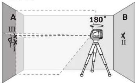
For this check, a free measuring distance of 5 m on a firm surface between two walls A and B is required.
- Mount the measuring tool onto a tripod or place it on a firm and level surface close to wall A. Switch on the measuring tool. Select cross-line operation with automatic levelling.

- Direct the laser against the close wall A and allow the measuring tool to level in. Mark the centre of the point where the laser lines cross each other on the wall (point 1).

- Turn the measuring tool by 180^ , allow it to level in and mark the cross point of the laser lines on the opposite wall B (point II).








English | 15
- Without turning the measuring tool, position it close to wall B. Switch the measuring tool on and allow it to level in.

- Align the height of the measuring tool (using a tripod or by underlaying, if required) in such a manner that the cross point of the laser lines is projected against the previously marked point IT on the wall B.
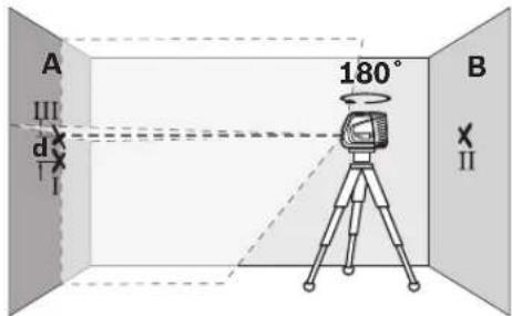
- Without changing the height, turn around the measuring tool by 180^ . Direct it against the wall A in such a manner that the vertical laser line runs through the already marked point I. Allow the measuring tool to level in and mark the cross point of the laser lines on the wall A (point III).
- The difference d of both marked points I and III on wall A indicates the actual height deviation of the measuring tool.
The maximum permitted deviation d_max is calculated as follows:
d_max = double distance of the walls x 0.3 mm/m Example: With a 5 metre distance between the walls, the maximum deviation must not exceed
d_max=2×5m×0.3mm/m=3mm . Thus, the marks must be more than 3 mm apart.
Checking the Levelling Accuracy of the Horizontal Line For the check, a free surface of approx. 5 x 5 metres is required.
- Set up the measuring tool on a firm, level surface between both walls A and B. Allow the measuring tool to level in while in horizontal operation.

- At a distance of 2.5 metres from the measuring tool, mark the centre of the laser line (point 1 on wall A and point 11 on wall B) on both walls.
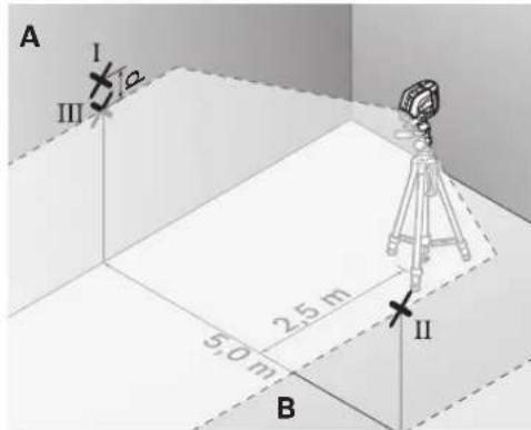
- Set up the measuring tool 5 metres away turned by 180^ is t not and allow it to level in.
- Align the height of the measuring tool (using a tripod or by underlaying, if required) in such a manner that the centre of the laser line is projected exactly against the previously marked point IT on wall B.
- Mark the centre of the laser line as point III (vertically above or below point I) on the wall A.
- The difference d of both marked points I and III on wall A indicates the actual deviation of the measuring tool from the level plane.
The maximum permitted deviation d_max is calculated as follows:
d_max = double distance of the walls x 0.3 mm/m Example: With a 5 metre distance between the walls, the maximum deviation must not exceed
d_max = 2 × 5 m × 0.3 mm/m = 3 mm . Thus, the marks must not be more than 3 mm apart.
16 | English
Checking the Levelling Accuracy of the Vertical Line
For this check, a door opening is required with at least 2.5 m of space (on a firm surface) to each side of the door.
- Position the measuring tool on a firm, level surface (not on a tripod) 2.5 m away from the door opening. Allow the measuring tool to level in while in cross-line operation mode, and direct the laser beams at the door opening.

- Mark the centre of the vertical laser line at the floor of the door opening (point 1), at a distance of 5m beyond the other side of the door opening (point 11) and at the upper edge of the door opening (point 111).
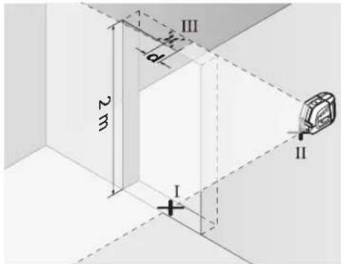
- Position the measuring tool on the other side of the door opening directly behind point 11. Allow the measuring tool to level in and align the vertical laser line in such a manner that its centre runs exactly through points 1 and 11.
- The difference d between point 111 and the centre of the laser line at the upper edge of the door opening results in the actual deviation of the measuring tool from the vertical plane.
- Measure the height of the door opening.
The maximum permitted deviation d_max is calculated as follows:
d_max = double height of the door opening x 0.3 mm/m Example: With a door opening height of 2 metres, the maximum permitted deviation is
d_max = 2 × 2 m × 0.3 mm/m = 1.2 mm . Thus, the marks must not be more than 1.2 mm apart.
Working Advice
▶ Always use the centre of the laser line for marking. The width of the laser line changes with the distance.
Working with the Alignment Plate
With the alignment plate 12, the measuring tool can be aligned by a reference line or the vertical laser line can be indicated at an angle of 45^ or 90^ to a reference line.
Position the measuring tool via the tripod mount 6 onto the pin 16 of the alignment plate. Position it in such a manner on the alignment plate that the vertical laser line (depending on the requested angle) runs centrally through the alignment aid 13, 14 or 15.
Align the alignment plate 12 with the corresponding alignment aids 13, 14 or 15 to the desired reference line.
Working with the Measuring Plate (Accessory) (see figures E-F)
With the measuring plate 20, it is possible to project the laser mark onto the floor or the laser height onto a wall.
With the zero field and the scale, the offset or drop to the required height can be measured and projected at another location. This eliminates the necessity of precisely adjusting the measuring tool to the height to be projected.
The measuring plate 20 has a reflective coating that enhances the visibility of the laser beam at greater distances or in intense sunlight. The brightness intensification can be seen only when viewing, parallel to the laser beam, onto the measuring plate.
Working with the Tripod (Accessory)
A tripod offers a stable, height-adjustable measuring support. Place the measuring tool via the tripod mount 6 onto the 1/4" male thread of the tripod and screw the locking screw of the tripod tight.
Working with the Laser Receiver (Accessory) (see figure G)
Under unfavourable light conditions (bright environment, direct sunlight) and for larger distances, use the laser receiver for improved finding of the laser lines 21. When working with the laser receiver, switch the pulse function on (see "Pulse Function", page 14).
Laser Viewing Glasses (Accessory)
The laser viewing glasses filter out the ambient light. This makes the red light of the laser appear brighter for the eyes.
▶ Do not use the laser viewing glasses as safety goggles. The laser viewing glasses are used for improved visualisation of the laser beam, but they do not protect against laser radiation.
Do not use the laser viewing glasses as sun glasses or in traffic. The laser viewing glasses do not afford complete UV protection and reduce colour perception.
Work Examples (see figures H-K)
Laying Flooring Plates at a 45° Angle (see figure J)
Position the measuring tool via the tripod mount 6 onto the pin 16 of the alignment plate. Position it in such a manner on the centred protrusion of the alignment plate 12 that the ver-






English | 17
tical laser line runs centrally through the alignment aid 15.
Then, align the alignment plate with the alignment aids 13 or 14 with regard to the reference line.
For cross line or in vertical operation, the vertical laser line on the floor indicates a 45^ angle to the reference line. Align the flooring plates with regard to this line.
Projecting Plumb Points to the Ceiling (see figure K)
Draw two lines crossed at a right angle through the point that you want to project to the ceiling. Place the alignment plate 12 onto the crossed lines and align it with the alignment aids 13 and 14 on the cross.
Position the measuring tool via the tripod mount 6 onto the pin 16 of the alignment plate. Position it in such a manner on one of the two outer protrusions on the alignment plate that the vertical laser line runs centrally through the corresponding alignment aid 13 or 14. Select vertical operation and draw the centre of the line running across the measuring tool to the ceiling.
Turn the measuring tool on the alignment plate by 90°. Pay attention not to move the position of the alignment plate. After levelling in, draw the cross point of the vertical laser line to the already drawn line. The cross point of both lines is the projected plumb point.
Maintenance and Service
Maintenance and Cleaning
Store and transport the measuring tool only in the protective pouch 17 or in the case 18.
Keep the measuring tool clean at all times.
Do not immerse the measuring tool in water or other fluids. Wipe off debris using a moist and soft cloth. Do not use any cleaning agents or solvents.
Regularly clean the surfaces at the exit opening of the laser in particular, and pay attention to any fluff or fibres.
For repairs, only send in the measuring tool in the protective pouch 17 or in the case 18.
Accessories
Protective Pouch 17 1609 203 X77
Case 18....2605438682
Laser Viewing Glasses 19 2 607 990 031
Measuring plate with foot 20....2 607 002 195
Laser Receiver 21 0601069100
Construction tripod BS 150 0601 096 B00
Universal holder BM 1 0601015A00
Telescopic rod BT 350....0 601 015 B00
After-sales Service and Application Service
Our after-sales service responds to your questions concerning maintenance and repair of your product as well as spare parts. Exploded views and information on spare parts can also be found under:
www.bosch-pt.com
Bosch's application service team will gladly answer questions concerning our products and their accessories.
In all correspondence and spare parts orders, please always include the 10-digit article number given on the nameplate of the product.
Great Britain
Robert Bosch Ltd. (B.S.C.)
P.O. Box 98
Broadwater Park
North Orbital Road
Denham
Uxbridge
UB 9 5HJ
At www.bosch-pt.co.uk you can order spare parts or arrange the collection of a product in need of servicing or repair.
Tel. Service: (0344) 7360109
E-Mail: boschservicecentre@bosch.com
Ireland
Origo Ltd.
Unit 23 Magna Drive
Magna Business Park
City West
Dublin 24
Tel. Service: (01) 4666700
Fax:(01)4666888
Australia, New Zealand and Pacific Islands
Robert Bosch Australia Pty. Ltd.
Power Tools
Locked Bag 66
Clayton South VIC 3169
Customer Contact Center
Inside Australia:
Phone: (01300) 307044
Fax: (01300) 307045
Inside New Zealand:
Phone: (0800) 543353
Fax: (0800) 428570
Outside AU and NZ:
Phone: +61 3 95415555
www.bosch.com.au
Republic of South Africa
Customer service
Hotline: (011) 6519600
Gauteng - BSC Service Centre
35 Roper Street, New Centre
Johannesburg
Tel.: (011) 4939375
Fax: (011) 4930126
E-Mail: bsctools@icon.co.za
KZN - BSC Service Centre
Unit E, Almar Centre
143 Crompton Street
Pinetown
Tel.: (031) 7012120
Fax: (031) 7012446
E-Mail: bsc.dur@za.bosch.com







18 | Français
Western Cape - BSC Service Centre
Democracy Way, Prosperity Park
Milnerton
Tel.: (021) 5512577
Fax: (021) 5513223
E-Mail: bsc@zsd.co.za
Bosch Headquarters
Midrand, Gauteng
Tel.: (011) 6519600
Fax: (011) 6519880
E-Mail: rbsa-hq.pts@za.bosch.com
Disposal
Measuring tools, accessories and packaging should be sorted for environmental-friendly recycling.
Do not dispose of measuring tools and batteries/rechargeable batteries into household waste!
Only for EC countries:

According to the European Guideline 2012/19/EU, measuring tools that are no longer usable, and according to the European Guideline 2006/66/EC, defective or used battery packs/batteries, must be collected separately and disposed of in an environmentally correct manner.
Batteries no longer suitable for use can be directly returned at:
Great Britain
Robert Bosch Ltd. (B.S.C.)
P.O. Box 98
Broadwater Park
North Orbital Road
Denham
Uxbridge
UB 9 5HJ
At www.bosch-pt.co.uk you can order spare parts or arrange the collection of a product in need of servicing or repair.
Tel. Service: (0344) 7360109
E-Mail: boschservicecentre@bosch.com
Subject to change without notice.
Français
Robert Bosch (France) S.A.S.
Português | 35

Bosch Service Center
Telegrafvej 3
2750 Ballerup
På www.bosch-pt.dk kan der online bestilles reservedele eller oprettes en reparations ordre.
Tlf. Service Center: 44898855
Fax: 44898755
E-Mail: vaerktoej@dk.bosch.com
Bortskaffelse
58 | Svenska
Bosch Service Center
Telegrafvej 3
2750 Ballerup
Danmark
Tel.: (08) 7501820 (inom Sverige)
Fax: (011) 187691
Avfallshantering
Robert Bosch Sp. z o.o.
Bosch Service Center PT
K Vápence 1621/16
692 01 Mikulov
Tel. service scule electrice: (021) 4057540
Fax: (021) 4057566
E-Mail: infoBSC@ro.bosch.com
- Usmerite laser na bliski zid A i nivelišite merni alat. Označite sredinu tačke, na kojoj ćete ukrstiti laserske linije na zidu (tačka 1).

- Okrenite merni alat za 180° nedostaje stepen, nivelišite ga i označite tačku ukrštanja laserskih linija na suprotnom zidu B (tačka II).
- Postavite merni alat ne okrećući ga blizu zida B, uključite ga i pustite da se niveliše.

- Postavite merni alat po visini tako (sa stativom ili u datom slučaju podmetačima), da tačka ukrštanja laserskih linija tačno pogadja prethodno označenu tačku II na zidu B.
– Okrenite merni alat za 180° nedostaje stepen, ne menjajući visinu. Upravite ga tako na zid A, da vertikalna laserska linija prolazi kroz već označenu tačku I. Nivelišite merni alat i označite tačku ukrštanja laserskih linija na zidu A (tačka ITI).





Srpski|145
- Razlika d već označenih tačaka 1 i 111 na zidu A daje stvarno odstupanje po visini mernog alata.
- Označite na 2,5 m rastojanja od mernog alata na oba zida sredinu laserske linije (tačka I na zidu A i tačka II na zidu B).

- Postavite merni alat okrenut za 180° nedostaje stepen na 5 m rastojanja i nivelišite ga.
- Postavite merni alat po visini tako (pomoću stativa ili u datom slučaju putem podmetača), da sredina laserske linije tačno pogadja prethodno označenu tačku 11 na zidu B.
- Označite na zidu A sredinu laserske linije kao tačku III (vertikalno preko odnosno ispod tačke I).
- Razlika d obe označene tačke 1 i 111 na zidu A daje stvarno odstupanje mernog alata od horizontale.
- Označite sredinu vertikalne laserske linije na podu otvora vrata (tačka 1), 5 m rastojanja druge strane otvora vrata (tačka 11), kao i na gornjoj ivici otvora vrata (tačka 111).

- Postavite merni alat na drugoj strani otvora vrata direktno iza tačke II. Nivelišite merni alat i postavite vertikalnu lasersku liniju tako, da njena sredina prolazi tačno kroz tačke I i II.
- Razlika d izmedju tačke III i sredine laserske linije na gornjoj ivici otvora vrata daje stvarno odstupanje mernog alata od vertikale.
- Merite visinu otvora vrata.
146 | Srpski
- Označite sredinu okomite linije lasera na dnu otvora vrata (točka I), na udaljenosti 5 m na drugoj strani otvora vrata (točka II), kao i na gornjem rubu otvora vrata (točka III).

- Märkige seadmest 2,5 m kaugusel mölemale seinale laserkiire keskpunkt (punkt I seinal A ja punkt II seinal B).

Lietuviškai | 173
Mechanics and Electronics Ltd.
PT/SAX-ASA
298 Bojeong-dong Giheung-gu
Yongin-si, Gyeonggi-do, 446-913
Republic of Korea
080-955-0909
처리
ภาษาไทย|195
Tâng 10,194 Golden Building
473 Diên Biên Phú
1609 92A 27R | (4.7.16) Bosch Power Tools


- GLL 2-50 Professional
- BOSCH
- | Deutsch
- Deutsch
- Sicherheitshinweise
- Product Description and Specifications
- Intended Use
- English | 13
- Product Features
- Assembly
- Inserting/Replacing the Batteries
- Operation
- Initial Operation
- Switching On and Off
- Deactivating the Automatic Shut-off
- | English
- Operation Modes (see figures A–D)
- Pulse Function
- Automatic Levelling
- Working with Automatic Levelling (see figure C)
- Working without Automatic Levelling (see figure D)
- Levelling Accuracy
- Influences on Accuracy
- Checking the Height Accuracy of the Horizontal Line
- English | 15
- | English
- Checking the Levelling Accuracy of the Vertical Line
- Working Advice
- Working with the Alignment Plate
- Working with the Measuring Plate (Accessory) (see figures E-F)
- Working with the Tripod (Accessory)
- Working with the Laser Receiver (Accessory) (see figure G)
- Laser Viewing Glasses (Accessory)
- Work Examples (see figures H-K)
- Laying Flooring Plates at a 45° Angle (see figure J)
- English | 17
- Projecting Plumb Points to the Ceiling (see figure K)
- Maintenance and Service
- Maintenance and Cleaning
- Accessories
- After-sales Service and Application Service
- www.bosch-pt.com
- Great Britain
- Ireland
- Australia, New Zealand and Pacific Islands
- Republic of South Africa
- Customer service
- Gauteng - BSC Service Centre
- KZN - BSC Service Centre
- | Français
- Western Cape - BSC Service Centre
- Bosch Headquarters
- Disposal
- Only for EC countries:
- Français
- Português | 35
- Bortskaffelse
- | Svenska
- Avfallshantering
- Srpski|145
- | Srpski
- Lietuviškai | 173
- 처리
- ภาษาไทย|195
Brand : BOSCH
Model : GLL 2-50 Professional
Category : Rangefinder