
EID500RE - Drill RYOBI - Free user manual and instructions
Find the device manual for free EID500RE RYOBI in PDF.
User questions about EID500RE RYOBI
0 question about this device. Answer the ones you know or ask your own.
Ask a new question about this device
Download the instructions for your Drill in PDF format for free! Find your manual EID500RE - RYOBI and take your electronic device back in hand. On this page are published all the documents necessary for the use of your device. EID500RE by RYOBI.
USER MANUAL EID500RE RYOBI
EID-500RE / EID-750REN
F PERCEUSE APERCUSSION MANUEL D'UTILISATION 1
IMPACT DRILL USER'S MANUAL 5
D SCHLAGBOHRMASCHINE BEDIENUNGSANLEITUNG 8
E TALADRADA DE PERCUSION MANUAL DE UTILIZACIOn 12
1 TRAPANO A PERCUSSIONE MANUALE D'USO 16
P BERBEQUIM DE PERCUSSAO MANUAL DE UTILIZAÇAO 20
NL KLOPBOOR GEBRUIKERSHANCEIDING 24
SLAGBORRMASKIN INSTRUKTIONSBOK 28
DK SLAGBOREMASKINE BRUGERVEJLEDNING 31
N SLAGBOREMASKIN BRUKSANVISNING 34
FIN ISKUPORAKONE KAYTTAJAN KASIKIRJA 37
GKPOYETIKO APANIANO OAHIGE XPHSH 40
HU UTVEFURO GEP HASZNALATI UTMUTATO 44
CZ PřÍKLEPOVÁ VRTACKA NÁVOD K OBSLUZE 48
RU YIAPHAJ IPEJIb PYKOBOIDCTBO IO 3KCIJYATAUHH 52
MAŞINÄ DE GÜRIT CU PERCUÜTIE MANUAL DE UTILIZARE 56
PL WIERTARKA UDAROWA INSTRUKCJA OBSLUGI 60
SLOUDARNI VRTALNIK UPORABNIISKI PRIROCNIK 64
HR RUČNA BUSILICA KORISNIČKI PRIRUCNIK 68
TR DARBELI MATKAP KULLANMA KILAVUZU 71
C∈□
| Attention! | Il est indispensable que vous lisiez les instructions contenues dans ce manuel avant le montage et la mise en service de l'appareil. |
| Important! | It is essential that you read the instructions in this manual before mounting and operating this machine. |
| Achtung! | Bitte lessen Sie unbedingt vor Montage und Inbetriebnahme die Hinweise dieser Bedienungsanleitung. |
| Àtenación! | Es imprescindible que lea las instrucciones de este manual antes del montaje y de la puesta en servicios. |
| Attenzione! | Prima di procedere al montaggio e alla messa in funzione, è indispensable leggere attendamente le istruzioni del presente manuale. |
| Atenção! | É indispensableavel as instruçõesdesto manual antes de montar e pör em服务于. |
| Let op! | Het is absolut neutzakelijkráor montage en inbedrijfstellingdeaanwijzingenindeazehandleiding te lezen. |
| Observera! | Det ar nödvändigt attläsa instruktionerna ienna bruksanvisning ffre montering och driftsättning. |
| OBS! | Denne brugsanvisning skal læsesigennem inden montering og ibrugtagning. |
| Advarsel! | Vennligst les instruksjonene ienna bruksanvisningen for du monterer og tar i bruk maskinen. |
| Huomio! | On ehdtoman välttämäntäluke tassä käytöhjeessa annetut objetennen asennusta ja käytöänottoa. |
| Προσχή! | Eviai anapaiτηto va διαβόσετε τις συστάσεις των Μθηγών αυτών πριν τη συναρμολόγηση και τη θεοδη σελειουργία |
| Figyelem! | Feltétlenül fontos, hógy a jelen használati utmutatóban foglalt elöirásokat az összeszerelés es az üzembe helyezés ellôt elolvassa! |
| Duležité upozorněnil! | Před montáží nařadiu vedením do provozu je nutné si prěcist následujíci poukny. |
| Bnuːmáne! | Πέρει sbórkòи iiianyckom hncstrpymènta Heobxódimo ilpočeṭb hncctpykùni n3 hactōnjüeρуkobojndcba. |
| Atentie! | Este indispensable sā cititi instructiunile continute in acest mod deutilizare inaunte de montaj.si de punerea in functiune. |
| Uwaga! | Przed montowaniemi u uruchomieniem, koniecznie musie sie Państwo zapoznać z zaleceniami zawartymi w niniejszym sponoble užycia. |
| Pomembno! | Zelo pomembno je, da pred namestitvijo in prvo uporabo te naprave preberete navodila v tem priročniku. |
| Upozorenje! | Vázno je da upute u ovom Korisničkom priručniku pročitatePRIPE postavljanja i uporabe ovog alata. |
| Dikkat! | Montajdan ve aletin kullanimina baslamadan bu kilavuzda bulunan talimatlari okumaniz gerekmektedir. |
Français
MERCI D'AVOIR ACHETÉ UN PRODUIT RYOBI
CHARACTERISTIQUES PRODUIT
| EID-500RE | EID-750REN | |
| Tension | 230 V ~ 50 Hz | 230 V ~ 50 Hz |
| Capacité du mandrin | 13 mm | 13 mm |
| Capacité de perçage | ||
| bois | 25 mm | 30 mm |
| acier | 10 mm | 13 mm |
| béton | 13 mm | 13 mm |
| Puisance absorbée | 500 W | 750 W |
THANK YOU FOR BUYING A RYOBI PRODUCT
To ensure your safety and satisfaction, carefully read through this OWNER'S MANUAL and the SAFETY INSTRUCTIONS before using the product.
INSTRUCTIONS FOR SAFE HANDLING
Make sure that the tool is only connected to the voltage marked on the name plate.
- Never use the tool if its cover or any bolts are missing. If the cover or bolts have been removed, replace them prior to use. Maintain all parts in good working order.
Always secure tools when working in elevated positions.
- Never touch the blade, drill bit, grinding wheel or other moving parts during use.
- Never start a tool when its rotating component is in contact with the work piece.
- Never lay a tool down before its moving parts have come to a complete stop.
- ACCESSORIES: The use of accessories or attachments other than those recommended in this manual might present a hazard.
REPLACEMENT PARTS: When servicing use only identical replacement parts.
WARNING: When using electric tools, basic safety precautions, including the following, should always be followed to reduce the risk of fire, electric shock and personal injury.
- Keep work area clean. Cluttered areas and benches invite injuries.
Consider work area environment. Do not expose power tools to rain. Do not use power tools in damp or wet locations. Keep work area lit. Do not use power tools where there is risk of fire or shock
Guard against electric shock. Avoid body contact with earthed or grounded surface (e.g. pipes, radiators, ranges, refrigerators).
- Keep children away. Do not let visitors touch the tool or extension cord. All visitors should be kept from area.
Store idle tools. When not it use, tools should be stored in a dry, high or locked up place, out of reach of children
- Do not force the tool. It will do the job better and safer at the rate for which it was intended.
Use the right tool. Do not force small tools or attachments to do the job of a heavy duty tool. Do not use tool for purposes not intended.
Use safety glasses. Also use face or dust mask if the cutting operation is dusty.
- Do not abuse the cord. Never carry the tool by the cord or yank it to disconnect it from the socket. Keep the cord away from heat, oil and sharp edges.
- Do not overreach. Keep proper footing and balance at all times.
- Maintain tool with care. Keep cutting tools sharp and clean for better and safer performance. Follow instructions for lubrication and changing accessories. Inspect tool cord periodically and if damaged have it repaired by an authorized service facility. Inspect extension cords periodically and replace if damaged. Keep handles dry, clean and free from oil and grease
- Disconnect tools when not in use, before servicing and when changing accessories such as blades, bits and cutters.
Avoid unintentional starting. Do not carry a plugged-in tool with a finger on the switch. Ensure that the machine is switched off before connecting to the power supply. - When tool is used outdoors, use only extension cords intended for outdoor use.
- Stay alert. Watch what you are doing. Use common sense. Do not operate tool when you are tired.
- Check for damaged parts. Before further use of the tool, a guard or other part that is damaged should be carefully checked to determine that it will operate properly and perform its intended function. Check for alignment, breakage of parts, mounting and any other conditions that may affect its operation. A guard or other part that is damaged should be properly repaired or replaced by an authorized service centre unless otherwise indicated in this instruction manual. Have defective parts replaced by an authorized service facility. Do not use the tool if the switch does not turn it on and off.
Make sure that the drill bit is securely mounted. An incorrectly mounted bit is extremely dangerous since it can fly off or break during drilling. - Dress properly. Do not wear loose clothing or jewellery, they can be caught in moving parts. Protective gloves and non-skid footwear are recommended when working outdoors. Wear protective hair covering to contain long hair.
Hold the tool securely with both hands. If not held securely, accidents or injury may result. - Never touch the chuck or metal body parts when drilling walls, floors, or other surfaces covering electrical wiring. Hold the tool only by the plastic handle to prevent electric shocks.
While operating, the work piece must be securely held with a vice or clamp to prevent it from moving due to the drill rotation.
English
SPECIFICATIONS
| EID-500RE | EID-750REN | |
| Voltage | 230 V ~ 50 Hz | 230 V ~ 50 Hz |
| Chuck capacity | 13 mm (1/2") | 13 mm (1/2") |
| Drilling capacity | ||
| in wood | 25 mm | 30 mm |
| in steel | 10 mm | 13 mm |
| in masonry | 13 mm | 13 mm |
| Input | 500 W | 750 W |
| No load speed | 0 - 2,700 min-1 | 0 - 2,800 min-1 |
| Blows per minute | 0 - 43,200 min-1 | 0 - 44,800 min-1 |
| Weight | 2.3 kg | 2.5 kg |
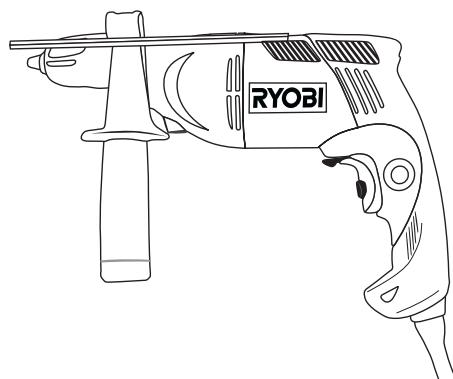
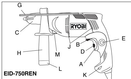
DESCRIPTION
A. Trigger Switch
B. Forward / Reverse Button
C. Keyless Chuck
D. Variable Speed Selector
E. Lock Button
F. Drill Mode Shift Knob
G. Depth Stopper
H. Auxiliary Handle
I. Bit
J. Air Vents
K. Live Tool Indicator
L. Bit Storage (EID-750REN)
M. Spindle Lock (EID-750REN)
STANDARD ACCESSORIES
Auxiliary handle, Depth Stopper, Drill Bit, Screw Bit & Wall anchor.
APPLICATIONS
(Use only for the purposes listed below.)
Drilling wood, materials and resin boards.
Drilling concrete (impact drilling only).
Drill metal: steel, brass, aluminum sheets, stainless steel & pipe.
NOISE BUILD-UP
Noise (sound pressure level) in the workplace can exceed 85 dB (A). In this case, sound insulation and hearing protection measures must be taken by the operator.
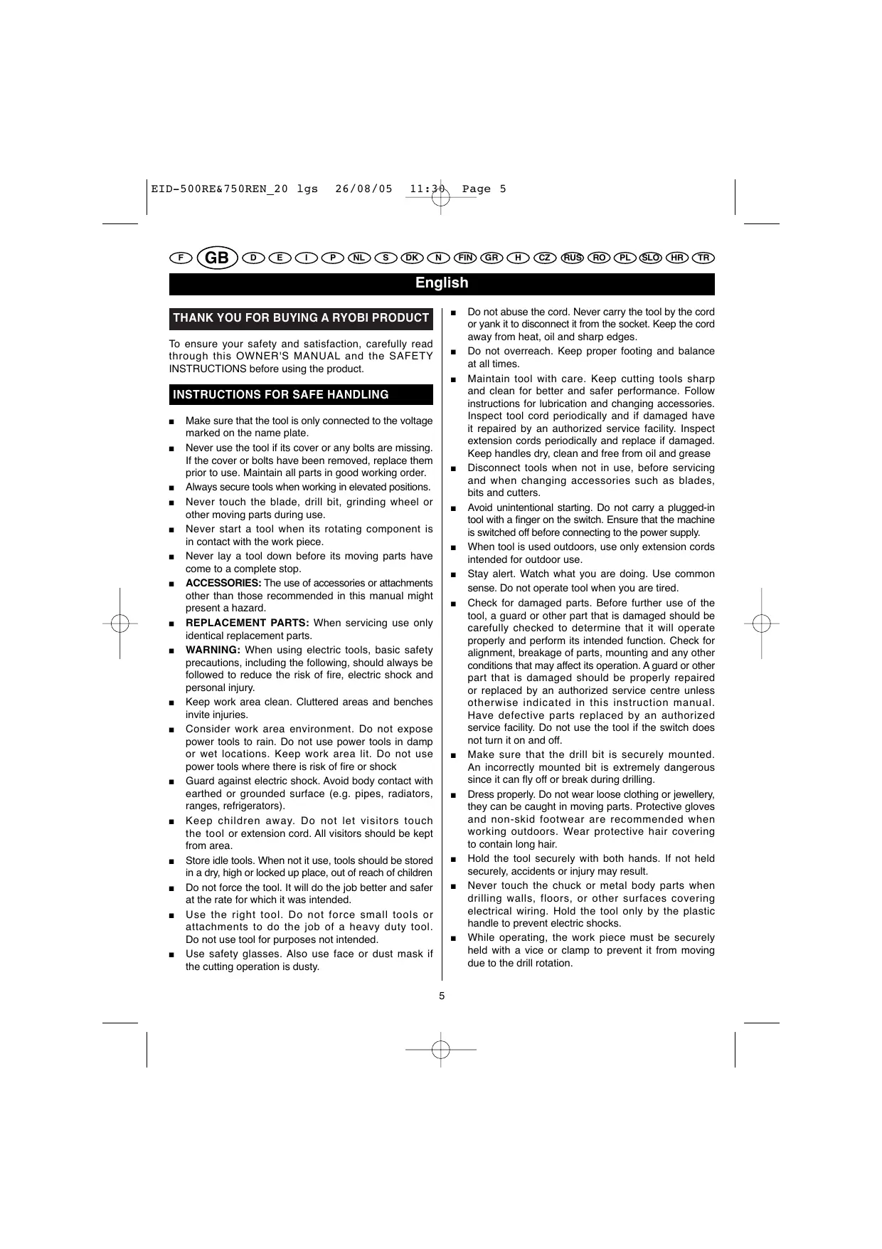
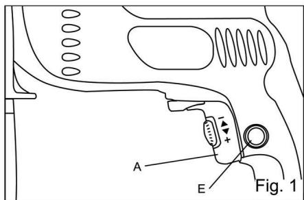
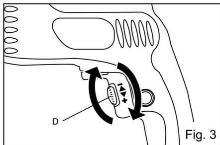
SWITCH (FIG. 1 & 3)
This tool is started and stopped by squeezing and releasing the trigger switch (A).
The speed can be adjusted in either gear by controlling the force applied to the trigger.
The maximum speed of the drill may be set at different speeds by adjusting the variable speed selector (D).
For continuous operation, press the lock button (E) while squeezing the trigger. Squeeze the trigger again to release the lock.
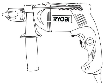
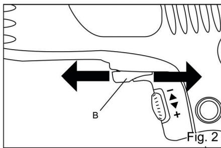
CHANGING THE ROTATION DIRECTION (FIG. 2)
To change the direction of rotation, stop the tool and push the forward / reverse button (B).
- When the forward button is pushed in, the bit rotates clockwise when viewed from the handle end of the tool.
- When the reverse button is pushed in, the bit rotates counterclockwise.
SPINDLE LOCK (EID-750REN)
For easy changing of the drill bit this drill is equipped with an automatic spindle lock (M) which holds the spindle stationary when loosening and tightening the chuck.
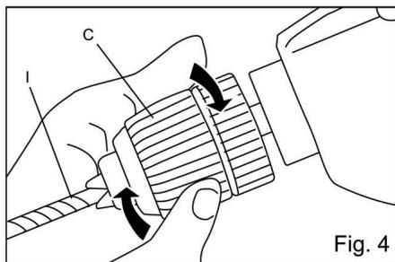
MOUNTING AND REMOving THE BIT (FIG. 4)
Insert the drill bit (l) into the chuck as far as the plain part of its shank will go.
- Tighten the chuck securely by rotate the chuck head in a clockwise direction.
The bit can be removed by rotate the chuck in a counterclockwise direction.
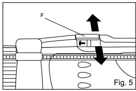
CHANGING BETWEEN DRILLING AND IMPACT DRILLING MODE (FIG. 5)
The drilling mode shift knob (F) for changing between the drilling mode and impact drilling mode is positioned on the top of the tool.
DRILLING MODE: Shift the knob to the " 一 _ 一 " symbol for rotation without impact action.
IMPACT DRILLING MODE: Shift the knob to the " 1- " symbol for impact drilling.
English
OPERATING
NEVER COVER THE AIR VENTS (J) SINCE THEY MUST ALWAYS BE OPEN FOR PROPER MOTOR COOLING.
DRILLING IN WOOD
To prevent ugly splits around the drill hole on the reverse side of the workpiece, put a piece of scrap timber under the work piece.
DRILLING IN METAL
Metals such as steel brass, aluminum sheets, stainless steel, and pipe may also be drilled. Mark the point to be drilled with a nail or punch.
Do not use impact mode on these materials.
DRILLING IN CONCRETE
Stone and masonry are generally drilled in the impact drilling mode.
When drilling in delicate materials such as wall tiles, it is essential to start with ordinary drilling and, once the tile is pierced, to continue with impact drilling.
In deep bore holes the drill bit should be pulled out occasionally in order to remove the debris from the drill and hole.
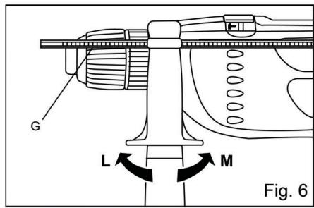
AUXILIARY HANDLE AND STOPPER POLE (FIG. 6)
Auxiliary handle
The auxiliary handle (H) can be rotated 360^ .
Loosen the handle grip by turning in direction L, and tighten it at an easy to-use position by turning the grip in direction M.
Depth stopper
Holes of a fixed depth can be accurately bored by using the depth stopper (G).
The depth of the hole will be the distance from the end of the bit to the end of the stopper pole.
By turning the handle grip in direction L, the stopper pole can be released and the depth adjusted. After adjusting the depth, fix the stopper pole again by turning the handle grip in direction M.
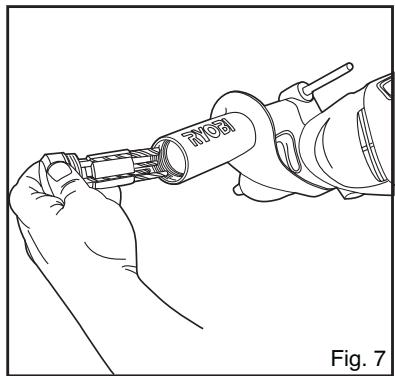
BIT STORAGE (EID-750REN) (FIG. 7)
The auxiliary handle also contains a compartment to store dill bits. To access this compartment unscrew the end cap below the yellow trim on the handle in an anticlockwise direction.
LIVE TOOL INDICATOR
This tool features a live tool indicator (K) which illuminates as soon as the tool is connected to the supply. This warns the user that the tool is connected and will operate when the switch is pressed.
MAINTENANCE
After use, check the tool to make sure that it is in good condition. It is recommended that you take this tool to a RYOBI Authorized Service Center for a thorough cleaning and lubrication at least once a year.
DO NOT MAKE ANY ADJUSTMENTS WHILE THE MOTOR IS IN MOTION. ALWAYS DISCONNECT THE POWER CORD FROM THE POWER SUPPLY BEFORE CHANGING REMOVABLE OR CONSUMABLE PARTS (BLADE, BIT, ETC.), LUBRICATING OR WORKING ON THE UNIT.

WARNING
To ensure safety and reliability, all repairs should be performed by an AUTHORIZED SERVICE CENTER or other QUALIFIED SERVICE ORGANIZATION.
SAVE THESE INSTRUCTIONS FOR FUTURE REFERENCE.
Deutsch
GATILLO (FIG. 1 Y 3)
GATILLO (FIG. 1 Y 3)
COMPARTIMENTO DE ARRUMACAO DAS BROCAS (EID-750REN) (FIG. 7)
STANDAARD ACCESSORIES
HOOFDSCHAKELAAR (AFB.1 EN 3)
HOOFDSCHAKELAAR (AFB.1 EN 3)
HULPHANDGREEP EN DIEPTEAANSLAG (AFB.6)
Hulphandgreep
U kunt de hulphandgreep (H) over 360^ verstellen.
TACK FÖR ATT DU KöPT EN PRODUKT FRÄN RYOBI
BITSFÖRVARING (EID-750REN) (FIG. 7)
SLAGBORING: Skub knappen mod symbolet " " for slagboring.
VIRKEMÄDE
PAS PÄ IKKE AT DÉKKE VENTILATIONSÄBNINGERNE (J) TIL, SÄ MOTOREN ALTID BLIVER TILSTRÄKKELIGT AFKÖLET.
BORING I TRAE
OPBEVARING AF BOR (EID-750REN) (FIG. 7)
ROM FOR OPPBEVARING AV BOR (EID-750REN) (FIG. 7)
TUOTTEEN TEKNISET TIEDOT
Xpnooioiote to dpavoo oac movo yia tic napakatw avapepoEvEc evapouyec:
I P O L 出 kalaaotikou.
- iatpnoi nptoou (movo kpoouotikn diatpnoi).
iatpnon x u a o x k 0 c, oi pakec aloumuivou, avo5eiodwotu xalua kai oI Owlanvcs.
EKOEESH STO OOPYBO
O topuoc (ntaunakouotikncpioc) oTo xpo epyaiaic uopei va Enepeae ta 85 dB A. TnV npintwn aut, O xphoTNC npene va laBcImuTa nXoovowkai vaoopa npooTateutika kauooutika.
KAN H ( ,1\& 3)
AΣΦΑΛΙΣH TOY TΣOK (EID-750REN)
To panaovocéivaeonlaioevoaeutouato ouotma aopalionc tou to onoio mlokapei to took otav to eoeiyvTe n to evaooyyTe.
TONOETHsH KAI AaIPEsH TOY TPYNANIoy (_X,4)
ToOnoTeTnTo OTeAExoc Tou Tpuanviou (I) 0oo nio paKpaI npopeiE meo oTo tOOK.
EavaoipTe yepa to tOOK oTpeovtac to daKTluo npoc ta deia.
Ia va apaiapeoetoteptunavi,otpεte To daKTtIoTo Tou Tpooc Ta apioTepa.
ENIIOH TH Σ ΛEITOYPRIA2 KPOYZHS (Σχ. 5)
To IAnktpo nou oac EInTpEnei va nepaTe SE tN 1eIoupyia KpoOnC (F) Bpioketai OTO enav Tmu Tou epyAeiou.
KANONIKO PANIANO: to nInktpo npoc to ouβoLo " yia nEpiotpoiXwpic kpooun.
YCTAHOBKA N CHRTHE CBEPJIA (puc.4)
BCTaBbTe CbePIO (I) yNopa B NaTPOH..
KpeIko 3aTAAHHTe IaTPOH,IOBepHyB KOJIbIO BnPaBO.
TTo6bI cHrTB cbepJIO, IOBopauHBAHTe KOJIIO BJIeBO.
OTBOHbIMMOJOTOK(puc.5)
BbIKIIOuateJIb OT6oHOrO MOJIoTka (F) HaxoIHtca CBepxY HHCTpymENTa.
HA HOPMAJIbHOJ IPEJIM:IOCTaBbTe BbIKIHOaTeJIb BIOIOJKeHne " ", YTO6bI JpeJIb pa6oTaJa 6e3 OT60HOro MOIOTKa.
HA IPEJIN C OTBOHHKOM: IOCTaBBTe BbIKJIHOuHaTeJIb BIOLOXKeHHe " ", TO6bI BKJIHOHTb OT0BJHBI MOJOTOK.
PABOTACJPEJIbIO
HE 3AKPbIBAIte BEHTHJIaIIHOHHbIE IIOJIOCTNI (J), YTO6bI HE MEIIIATb HOPMAJIbHOMY OXIAJKDEHNIO MOTOPA.
CBEPJIEHNE DEPEBA
UTo6bI N36eKaTb Iepe6HH BOKpyr OTBepcTTH C o6paTHOH cTOPOHb 3aOTOBKn, INoKJIaNBAHTe NOI Hee pepeBHNHyO nAnHeJIb.
CBEPJIEHHE METAJIJA
IpeJIb MoKET CBePJIHTb MeTJIb, TAKHe KAc cTJIb HIN MEJb, aJIOMHHneBbIe IIaTcHbIb, HePKaBeHy HIN TPy6Ib. OTMeTbTe rBO3JeM HIN KePHOM MecTo, rJa HAno IpcocBepJIbTb OTBcTHe.
He noJIb3yIITecb cyHKnHne OT60HHKa Ha 3ToM MaTepeHaJIe.
CBEPJIEHNE BETOHA
KaMeHb H 6eTOH O6bUHO CBepJIaTcI IpeJIbIO C OT6oIHbIM MOJIoTkOM.
PnCbePJIeHHXpyIKNoMaTePHaJa,HaIpnHMePIIHTKHeO6xOJHMoHaHNaHbpaOToB HopMaJIbHOMpeKHM,aIOTOMIpeXoJITbHaYapHbIpeKHM.
PIN CBEPIENH IYI60KHX OTBEPCTH peryJIyHO BIIHNMAITE CBEPIIO H3 OTBEPCTTH, YTObI yuaJIHTb H3 HeO H3 OTBEPCTTH CTpyKky H IIbIb.
BCIOMOTATEJIbHAApyKA HYIOPTJYBHNHbI(pnc.6)
Bcnoomogatelebna pyka
BcnoMoTeJIbHa pyka (H) MoKet IOBopaHbTa bca Ha 360^
Pa36JIOKpyIte pyUy, IOBOPaYHbAe ee B HApapBJeHH L, H a36JIOKpyIte ee B yOboHOM pa6ooyem NIOJOKeHH, IOBOPaYHbA H npapBJeHH M.
Ynop rIy6HbI
YIop rIy6HbI (G) IIO3BOJIAET CBePJIHTb TOUHbIe OTBepCTHa 3aDaHHyO rIy6HHy.
TJy6HnA OTBepCTNa COOTBeTcTByET paCtOHHIO MekJy KOHOM CBePJIa N yIIpOM Tjy6HbI.
UTo6bI pa36IIOKHpOBaTb ynp H I3MeHnHtB erO peryInpOBky, NOBOPaIBaTE pyKy B HApPabJIeHN L. HAcTPONB rJy6Hny CBePJIeHN, 3a6IIOKpyTe ynp, IOBOpaYINBa pyKy B HApPabJIeHN M.
OTJEJHEHNEIJI CBEPI (EID-750REN) (Pnc.7)
BcHOMORAteJIbHaY pyKoTka IpeJI -IOJIa. B HeI MoXHO epKAtb CMeHbIe CbeJIa. YTo6bl OTKpItb OTJeJIeHHe IJIa CBepII, OTBnHTIne KpbIbIKy IOJ KeJIbIM pe6pOM BCNIOMORAteJIbHO pyKoTkn.
Pysckn
INIKATOPIHTAHNA
HnctpymEHT Hmeet HHnKATop IHTaHn (K), KOTOpbI 3aropaetc, KOrHa HCTpyMeT BkIoUeH B cTeB. 3ToT HnHKnATop yKa3bIbaeT Ha TO, YTO HnCTpyMeT BkIoUeH B cTeB n 3aunCTTnC T npH kauTHn HA KypOK.
OBCIYXHBAHNE
Iocne pa6oTb npoepeRte pa6oee coctOHHnHcTpymeHTA. PekomeHyETcH He peXe p3a B FoD cAbatb HnCTpymeHTB I CHeTp TexHHueckoO6ClyKhbHaHHryobIIJIOHO mCA3Kn IIYCTKN.
HE IPOH3BOJNTE HNUKAKHX PEGYJINPOBOK IIPII PA6OTAOIIEM MOTOPE. BCEITDA OTKJIIOUATE CETEOB IIHHYP IIPEEI 3AMEHOI AKCECCYAPOB H3HAIIINBAEMbIX IETAJIEN (IIOJIOTHO, HAKOHEYNHK, H.T.D.) A TAKJE IIPEXJE YEM CMA3bIBATb HHCTPYMEHT HJIM MAHNIIYJINPOBATb HM.

BHUMAHNE
Дябьиб 6e3oIacHocTHиHaJIeKHOCTN BcepeMOHTbIe pa6ObTIdoJIXbI bblIOJIHrTcBvIeHTpeTexHueckoro O6cIyXHBaHHaRyobi.
COXPAHHTE HACTOIIHNE IHCTPYKIIH JIJI IIOCEJEYIOIIHX KOHCJYJBTAIIH.
Romána
VA MULTUMIM PENTRU INCREDEREA CE NE ACORDATI CUMPÁRÁND UN PRODUS RYOBI
Pentru autiliza optim si in deplina sigurantautilajul,citiin prealabil, cu atentie MANUALLDE UTILIZAREsi MASURILE DE SECURITATE.
MÁSURI DE SECURITATE
(EID-750REN) (FIG. 7)
NAVODILA ZA VARNO UPORABO
NAVODILA ZA VARNO UPORABO
GARANTIE - CONDITIONS
All Ryobi products are guaranteed against manufacturing defects and defective parts for a period of twenty four (24) months from the date stated on the original invoice drawn up by the retailer and given to the end user. Deterioration caused by normal wear and tear, unauthorised or improper use or maintenance, or overload are excluded from this guarantee as are accessories such as battery packs, light bulbs, blades, fittings, bags, etc. In the event of malfunction during the warranty period, please take the NON-DISMANTLED product, along with the proof of purchase, to your retailer or nearest Authorised Ryobi Service Centre.
This warranty in no way affects your legal rights concerning defective products.

DECLARATION OF CONFORMITY
We declare under our sole responsibility that this product is in conformity with the following standards or standardized documents. 89/336/EEC, 98/37/EEC, EN50144, EN55014, EN61000-3-2, EN61000-3-3

Name of company: Address:
Ryobi Technologies FRANCE S.A. Z.I. PARIS NORD II 209, RUE DE LA BELLE ETOILE 95700 ROISSY EN FRANCE FRANCE
Tel: +33-1-49 90 14 14 Fax: +33-1-49 90 14 29
Name of company: Address:
Ryobi Technologies (UK) Limited. ANVIL HOUSE, TUN'S LANE, HENLEY-ON-THAMES, OXFORDSHIRE, RG9 1SA UNITED KINGDOM
Tel: +44-1491-848700 Fax: +44-1491-848701
Name of company: Address:
Ryobi Technologies GmbH
ITTERPARK 7
D-40724 HILDEN GERMANY
Tel: +49-2103-29580 Fax: +49-2103-295829
Type: EID-500RE / EID-750REN
Name/Title: Michel Volleau
Name/Title: Mark Pearson Managing Director
Signature:

Name/Title: Walter Martin Eichinger General Manager
Signature: