
SBE 1000 - Hammer drill METABO - Free user manual and instructions
Find the device manual for free SBE 1000 METABO in PDF.





| Product type | Hammer drill |
| Brand | METABO |
| Model | SBE 1000 |
| Power supply | Mains (230 V, 50/60 Hz typical) |
| Power input | 1000 W (estimated based on model) |
| Protection class | II (double insulation) |
| Current type | Alternating current (AC) |
| Chuck | Keyed chuck or Futuro Plus/Top automatic chuck (depending on equipment) |
| Speed selector | Yes, 2 mechanical speeds |
| Rotation direction switch | Yes (left/right) |
| Additional handle | Yes, included |
| Depth stop | Yes |
| Hammer function | Yes, adjustable |
| Torque limitation | Yes, adjustable (6 positions + continuous without limitation) |
| Impact function | Yes, for screwing/unscrewing |
| Electronic indicator | Restart protection (rapid flashing) |
| Safety clutch | Metabo S-automatic |
| Continuous operation | Yes, via button |
| Usage | Drilling without hammer (metal, wood, plastic), drilling with hammer (concrete, stone), screwing, tapping |
| Noise level | Wear ear protection (value not specified) |
| Maintenance | Clean chuck, replace carbon brushes via service center |
| Accessories | Use only Metabo accessories |
| Repairs | By specialist, contact Metabo representative |
Frequently Asked Questions - SBE 1000 METABO
User questions about SBE 1000 METABO
0 question about this device. Answer the ones you know or ask your own.
Ask a new question about this device
Download the instructions for your Hammer drill in PDF format for free! Find your manual SBE 1000 - METABO and take your electronic device back in hand. On this page are published all the documents necessary for the use of your device. SBE 1000 by METABO.
USER MANUAL SBE 1000 METABO
Original instructions
1. Declaration of Conformity
We declare under our sole responsibility that these impact drills comply with the specified standards and directives. (See Fig. P)
2. Specified Use
The machine is suitable for drilling, without impact, in metal, wood, plastic and similar materials, and for impact drilling in concrete, stone and similar materials. It is also suitable for thread tapping and for screwdriving (not SB 710).
The user bears sole responsibility for any damage caused by improper use.
Generally accepted accident prevention regulations and the enclosed safety information must be observed.
3. General Safety Instructions

WARNING - Reading the operating instructions will reduce the risk of injury.

WARNING Read all safety warnings and instructions. Failure to follow all safety warnings and instructions may result in electric shock, fire and/or serious injury.
ings and instructions may result in electric shock, fire and/or serious injury.
Keep all safety instructions and information for future reference.
Pass on your power tool only together with these documents.
For your own protection and for the protection of your power tool, pay attention to all parts of the text that are marked with this symbol!

For your own protection and for the protection of your power tool, pay attention to all parts of the text that are marked with this symbol!
Wear ear protectors when impact drilling.
Exposure to noise can cause hearing loss.
Use the additional handle supplied with the tool. Loss of control can cause personal injury.
Hold the power tool by insulated gripping surfaces, when performing an operation where the cutting accessory may contact hidden wiring or its own cord. Cutting accessory contacting a "live" wire may make exposed metal parts of the electrical tool "live" and could give the operator an electric shock.
Pull the plug out of the plug socket before any adjustments or servicing are performed.
Avoid inadvertent starts by always unlocking the switch when the plug is removed from the mains socket or in case of a power cut.
Ensure that the spot where you wish to work is free of power cables, gas lines or water pipes (e.g. using a metal detector).
Smaller workpieces must be secured such that they are not carried along with the drill bit when drilling (e.g. by clamping in a vice or on a work bench with screw clamps).
Keep hands away from the rotating tool! Remove chips and similar material only with the machine at standstill.
Metabo S-automatic safety clutch. When the safety clutch responds, switch off the machine immediately! If the tool jams or catches, the power supply to the motor is restricted. Due to the strong force which can arise, always hold the machine with both hands using the handles provided, stand securely and concentrate.
The Metabo S-automatic safety clutch must not be used for torque control.
Caution with hard screwdriving (driving of screws with either a metric or an imperial thread into steel)! The head of the screw may rip off or high restoring torques may be incurred at the handle.
Dust from material such as paint containing lead, some wood species, minerals and metal may be harmful. Contact with or inhalation of the dust may cause allergic reactions and/or respiratory diseases to the operator or bystanders.
Certain kinds of dust are classified as carcinogenic such as oak and beech dust especially in conjunction with additives for wood conditioning (chromate, wood preservative). Material containing asbestos must only be treated by specialists.
- Where the use of a dust extraction device is possible it shall be used.
- The work place must be well ventilated.
- The use of a dust mask of filter class P2 is recommended.
Follow national requirements for the materials you want to work with.
5. Figures
Illustrations are provided at the beginning of the operating instructions.
Symbol explanation:

Normal drilling/Drill bit

Impact drilling

Movement direction

Driving screws/Screw

Slow
Thread tapping/Thread tapper
6. Overview

Fig. A
1 Thumb-wheel for gear selection 2 Additional handle/Additional handle with vibration damping * 3 Depth stop 4 Geared chuck * 5 Futuro Plus keyless chuck 6 Futuro Top keyless chuck * 7 Sliding switch (normal drilling/impact drilling) 8 Speed preselection wheel * 9 Setting wheel for torque control and impulse function * 10 Electronic signal indicator 11 Rotation selector switch * 12 Lock button for continuous activation 13 Trigger depending on model
7. Initial Operation

Before plugging in the device, check to see that the rated mains voltage and mains
frequency, as specified on the rating label, match your power supply.

To guarantee secure purchase of the chuck: After initial drilling (clockwise), use a screw to firmly tighten the safety screw inside the chuck (if available/depending on the model).
THE SAFETY SCREW HAS A LEFT-HANDED THREAD!
7.1 Fitting the additional handle (2) → Fig. B

For safety reasons, always use the additional handle supplied.
Tighten the additional handle firmly by turning it.
8. Use
8.1 Setting depth stop → Fig. C 8.2 Setting direction of rotation, transporting safety device (switch-on lock) → Fig. D Do not activate the rotation selector switch (11) unless the motor has completely stopped. 8.3 Setting for normal drilling, impact drilling → Fig. E Impact drilling and normal drilling only in a clockwise direction. 8.4 Selecting gear → Fig. F ! Change thumbwheel (1) only when the machine is in the process of running down (briefly switch it on and off).
8.5 Setting torque control, impulse function → Fig. G
Position 1-6: The motor comes to a complete stop when the preselected torque is reached.
1 = low torque, 6 = high torque, + = no torque control (max. torque, for drilling). The impulse function is switched on constantly (to facilitate tightening and releasing screws that are tight even when the screw heads are damaged, and to enable clean drilling without centre punching in tiles, aluminium, or other materials).
8.6 Preselecting rotational speed → Fig. H. See the table for recommended rotational speeds for drilling.
8.7 Switching On and Off
Switching on, rotational speed → Fig. A: Press the trigger (13).
Release the trigger to switch off.
Continuous operation → Fig. A: With the trigger (13) pressed, push in the locking button (12) and release the trigger. Press and release the trigger (13) again to switch off.
In continuous operation, the machine continues running if it is forced out of your hands. Therefore, always hold the machine with both hands using the handles provided, stand in a safe position, and concentrate.
8.8 Tool change, Futuro Top keyless chuck (6) → Fig. I
Clamp the tool by turning the sleeve firmly to its stop.
8.9 Tool change, Plus (5) keyless chuck → Fig. J
The ratchet sound that can possibly be heard after opening the drill chuck is functional and is switched off by a reverse rotation of the sleeve.
If the chuck is very tightly closed: Firmly grip the chuck with an open-end spanner at the chuck head and firmly turn the sleeve in the direction of the arrow -1.
Clamping the tool
- Insert the tool -2- as far as possible.
- Using one hand, hold the retainer ring securely (depending on fittings).
- Turn sleeve in direction -3- until the noticeable mechanical resistance has been overcome.
- Caution! The tool is not yet fully tightened! Keep turning the sleeve (it must "click" when turning) until it cannot be turned any further - only now is the tool safely clamped.
With a soft tool shank, retightening may be required after a short period of operation.
8.10 Tool change, geared chuck (4) → Fig. K
8.11 Unscrew the chuck (when driving screws without the chuck or for use with attachments) ⇒ Fig. L, M, or N
Note for Fig. M, N: Release by tapping lightly with a rubber hammer, as shown, and unscrew.
Note: If a bit clamping bush (order no. 6.31281) is attached, the screwdriver bit inserted in the hexagon socket of the spindle is held in place.
9. Cleaning, Maintenance
Keyless chuck cleaning:
After prolonged use hold the chuck vertically, with the opening facing down, and fully open and close it several times. The dust collected falls from the opening. The application of cleaning spray to the jaws and jaw openings at regular intervals is recommended.
10. Troubleshooting
Electronic signal display (10):
Rapid flashing - restart protection
(SBE 1000, SBE 1100 Plus)
When power is restored after a power failure, the machine - which is still switched on - will not start for safety reasons. Switch machine on and off again.
Slow flashing - carbon brushes worn (SBE 1100 Plus)
The carbon brushes are almost completely worn. If the brushes are completely worn, the machine switches off automatically. Have the brushes replaced by an authorized service centre.
Permanently lit - overload (SBE 1100 Plus)
If the machine is subject to long periods of continuous overloading, the power input of the machine is limited. This prevents the further unauthorized heating of the motor.
11. Accessories
Use only genuine Metabo accessories.
Use only accessories which fulfil the requirements and specifications listed in these operating instructions.
Fit accessories securely. Secure the machine if it is operated in a bracket. Loss of control can cause personal injury.
For a complete range of accessories, see www.metabo.com or the main catalogue.
12. Repairs
Repairs to electrical tools must be carried out by qualified electricians ONLY!
If you have Metabo electrical tools that require repairs, please contact your Metabo service centre. For addresses see www.metabo.com.
You can download spare parts lists from www.metabo.com.
13. Environmental Protection
Observe national regulations on environmentally compatible disposal and on the recycling of disused machines, packaging and accessories.
Only for EU countries: Never dispose of power tools in your household waste! In accordance with European Guideline 2002/96/EC on used electronic and electric equipment and its implementation in national legal systems, used power tools must be collected separately and handed in for environmentally compatible recycling.
14. Technical Specifications
See Fig. O. We reserve the right to make technical improvements.
P1 = Rated input
P2 = Power output
n1* = No-load speed
n2* = Load speed
max. dia. = Max. solid drill diameter
s max = Max. impact rate
b = Chuck capacity
G = Spindle thread
H = Spindle with hexagon socket
m = Weight
D = Collar diameter
Measured values determined in conformity with EN 60745.
Machine in protection class II
~ Alternating current
The technical specifications quoted are subject to tolerances (in compliance with the relevant valid standards).
- Energy-rich, high-frequency interference can cause fluctuations in speed. The fluctuations disappear, however, as soon as the interference fades away.

Emission values
Using these values, you can estimate the emissions from this power tool and compare these with the values emitted by other power tools. The actual values may be higher or lower, depending on the particular application and the condition of the tool or power tool. In estimating the values, you should also include work breaks and periods of low use. Based on the estimated emission values, specify protective measures for the user - for example, any organisational steps that must be put in place.
Vibration total value (vector sum of three directions) determined in accordance with EN 60745:
a_h, ID = Vibration emission value (impact drilling into concrete)
a_h, D = Vibration emission value (drilling into metal)
K_h,1D, K_h,D = Uncertainty (vibration)
Typical A-effective perceived sound levels:
LpA = Sound pressure level
Permanent ignition - overload (SBE 1100 Plus)
H = Hex socket
m = Weight
D = Diameter of the collar
ah, ID = vibration emission value (impact drilling in concrete)
ah,D = vibration emission value (drilling in metal)
Kh,ID, Kh,D = inaccuracy (vibrations)
Normal, A-weighted sound level:
LpA = sound pressure level
LWA = sound power level
KDA KWA = Uncertainty

Use hearing protection!
Max. = maximum drill diameter
Spare parts lists can be downloaded at www.metabo.com.
13. Environmental protection
ah,D = vibration emission (drilling in metal)
Kh,1D, Kh,D = Uncertainty (vibration)
To the parameters of the electrical network indicated on the factory plate.

For easier chuck replacement: after the first
drilling (right rotation), tighten the locking screw inside the chuck with a screwdriver
(depending on the model). Left-hand thread!
7.1 Installing the auxiliary handle (2) → Fig. B
For safety reasons, always use the auxiliary handle included in the delivery.
Tighten the auxiliary handle firmly by turning it.
8. Operation
8.1 Adjusting the depth stop → Fig. C
8.2 Adjusting the direction of rotation, setting the lock for transport (lock-off)
Fig. D
Only switch the direction of rotation (10) when the motor is at a standstill.
8.3 Adjusting the mode for normal/impact drilling → Fig. E
Drilling and impact drilling are only possible with right rotation.
8.4 Selecting the speed → Fig. F
Switch on/off (1) Perform only during the time specified in the instrument's instructions, after switching off (briefly switch on/off).
8.5 Adjustment of torque limit, pulse mode → fig. G
Positions 1-6: when the preset torque is reached, the electric motor stops.
1 = LOW TORQUE
6 = HIGH TORQUE
- =No torque limit (max. torque for drilling)
=Pulse mode, always on (for loosening and tightening tightly stuck screws, even damaged ones; to prevent bit slipping at the start of drilling without a center punch when drilling into ceramic tiles, aluminum, or other materials.)
8.6 Setting the rotation speed
Recommended rotation speed values for drilling, see table.
8.7 Switching on/off
Switching on, rotation speed → fig. A: press the switch (13).
To switch off, release the switch.
Continuous operation → fig. A: with the switch (13) pressed, press the lock button (12) and release the switch. To switch off, press the switch (13) again, then release it.

In continuous mode, the instrument continues to work even if it is
pulled out of your hands. Therefore, always hold the power tool firmly with both hands on the handles, maintain a stable position, and concentrate all your attention on the work being performed.
8.8 Changing the tool / quick-change chuck Futuro Top (6)
Fig. 1
Tool locking: Turn the sleeve with force until it stops.
8.9 Changing the tool / quick-change chuck Plus (5) → Fig. J
The cracking that may be heard after opening the chuck (due to the design) is eliminated by turning the sleeve in the opposite direction.
If the chuck is tightened too strongly: Hold the drill chuck with the open-end wrench by the chuck head and turn the sleeve with force in the direction of the arrow (1-).
Clamping the tool:
- Insert the tool -2- as deep as possible.
- Hold the locking ring (depending on the equipment) with your hand,
- turn the sleeve in the direction of the arrow 3- until a noticeable mechanical resistance is felt. -Attention! The tool is not yet clamped at this point! Continue turning with force (the arrows must be aligned) until the stop - only then is the tool clamped securely.
Tools with a shank made of soft material must be re-tightened after a longer drilling time.
8.10 Changing the tool / chuck with toothed ring (4) → Fig. K
8.11 Unscrew the drill chuck (for drilling without a drill chuck or for using accessories) Fig. L, M, N
Note for Fig. L, M, N: Loosen with light hammer blows on the wrench (see Fig.).
Note: When the locking sleeve 1/8" is installed (order no. 6.31281), the wrench must be inserted with a hexagonal pin.
9. Cleaning, Maintenance
Cleaning the quick-change drill chuck; after prolonged use, set the drill chuck vertically with the opening facing down, open and close it fully several times. Accumulated dust will fall out through the opening. It is recommended to regularly apply an aerosol spray lubricant to the clamping jaws and the openings between the clamping jaws.
10. Troubleshooting
Electronic signal indicator (10) Frequent flashing - protection against kickback (SBE 1000, SBE 1100 Plus)
Restart protection After a power failure, the tool restarts automatically when it is switched back on. Switch the tool off and on again.
Frequent flashing - carbon brush wear (SBE 1100 Plus)
Premature carbon brush wear. When the carbon brushes are worn, the tool switches off automatically. Have the carbon brushes replaced at a service center.
Continuous flashing - overload (SBE 1100 Plus)
In case of prolonged overload, the power consumption of the tool is limited, which prevents further unacceptable heating of the motor.
11. Accessories
Use only original Metabo accessories.
Use only accessories that meet the requirements and parameters specified in this operating manual.
Securely attach accessories. When using the power tool in a stand: securely clamp the power tool. The tool and the accessory may become loose and cause injury.
Noise and vibration values
These values allow the noise and vibration generated during operation of various power tools to be assessed and compared. Depending on the operating conditions, the condition of the power tool and the working (insert) tools, the actual load may be higher or lower. When determining the vibration level, take into account interruptions and periods of operation at reduced (idle) load. Determine the scope of organizational measures for protection
The vibration values take into account the additional values of noise and vibration.
The sum of the three directions is calculated in accordance with EN 60745:
a_h, ID = vibration value (impact drilling in concrete)
a_h, D = vibration value (drilling in metal)
K_h, ID, K_h, D = uncertainty coefficient (vibration)
Noise levels according to the standard:
LpA = sound pressure level
LWA = sound power level
KpA, KWA = uncertainty coefficient
Wear protective goggles!
PROFESSIONAL POWER TOOLS
metabo®
work. don't play.
Metabowerke GmbH, 72622 Nürtingen, Germany www.metabo.com
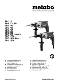


- ORIGINAL INSTRUCTIONS
- DECLARATION OF CONFORMITY
- SPECIFIED USE
- GENERAL SAFETY INSTRUCTIONS
- FOR YOUR OWN PROTECTION AND FOR THE PROTECTION OF YOUR POWER TOOL, PAY ATTENTION TO ALL PARTS OF THE TEXT THAT ARE MARKED WITH THIS SYMBOL
- FIGURES
- SYMBOL EXPLANATION
- OVERVIEW
- FIG. A
- INITIAL OPERATION
- USE
- SETTING TORQUE CONTROL, IMPULSE FUNCTION → FIG. G
- PRESELECTING ROTATIONAL SPEED → FIG. H. SEE THE TABLE FOR RECOMMENDED ROTATIONAL SPEEDS FOR DRILLING
- SWITCHING ON AND OFF
- TOOL CHANGE, FUTURO TOP KEYLESS CHUCK (6) → FIG. I
- TOOL CHANGE, PLUS (5) KEYLESS CHUCK → FIG. J
- UNSCREW THE CHUCK (WHEN DRIVING SCREWS WITHOUT THE CHUCK OR FOR USE WITH ATTACHMENTS) ⇒ FIG. L, M, OR N
- CLEANING, MAINTENANCE
- TROUBLESHOOTING
- ACCESSORIES
- REPAIRS
- ENVIRONMENTAL PROTECTION
- TECHNICAL SPECIFICATIONS
- EMISSION VALUES
- INSTALLING THE AUXILIARY HANDLE (2) → FIG. B
- OPERATION
- ADJUSTING THE DEPTH STOP → FIG. C
- ADJUSTING THE DIRECTION OF ROTATION, SETTING THE LOCK FOR TRANSPORT (LOCK-OFF)
- ADJUSTING THE MODE FOR NORMAL/IMPACT DRILLING → FIG. E
- SELECTING THE SPEED → FIG. F
- ADJUSTMENT OF TORQUE LIMIT, PULSE MODE → FIG. G
- SETTING THE ROTATION SPEED
- SWITCHING ON/OFF
- CHANGING THE TOOL / QUICK-CHANGE CHUCK FUTURO TOP (6)
- CHANGING THE TOOL / QUICK-CHANGE CHUCK PLUS (5) → FIG. J
- CHANGING THE TOOL / CHUCK WITH TOOTHED RING (4) → FIG. K
- UNSCREW THE DRILL CHUCK (FOR DRILLING WITHOUT A DRILL CHUCK OR FOR USING ACCESSORIES) FIG. L, M, N
- NOISE AND VIBRATION VALUES
- METABO®
- WORK. DON'T PLAY
Brand : METABO
Model : SBE 1000
Category : Hammer drill