
SB 710 SBE 701 SP SBE 710 SBE 730 SBE 751 SBE 850 SBE 900 Impuls SBE 1000 SBE 1100 Plus SBE 1300 - Hammer drill METABO - Free user manual and instructions
Find the device manual for free SB 710 SBE 701 SP SBE 710 SBE 730 SBE 751 SBE 850 SBE 900 Impuls SBE 1000 SBE 1100 Plus SBE 1300 METABO in PDF.
| Product type | Impact drill |
| Brand | Metabo |
| Compatible models | SB 710, SBE 701 SP, SBE 710, SBE 730, SBE 751, SBE 850, SBE 900 Impuls, SBE 1000, SBE 1100 Plus, SBE 1300 |
| Input power | From 710 W to 1300 W depending on model |
| Weight | Approximately 2.5 kg (depending on model) |
| Maximum drilling capacity | Wood: up to 50 mm, Steel: up to 20 mm, Concrete: up to 32 mm (depending on model) |
| Chuck | Keyed chuck or automatic Futuro Plus/Top chuck depending on model |
| Main functions | Drilling with/without impact, 2-speed selection, speed presetting, adjustable torque limitation (1-6 + release), impulse function, continuous operation, S-automatic safety clutch |
| Drilling modes | Normal drilling, drilling with impact |
| Variable speed trigger | Yes, via trigger |
| Mechanical speed selector | Yes, 2 ranges |
| Torque limitation | Adjustable from 1 (low) to 6 (high) + position without limitation |
| Impulse function | For screwdriving/unscrewing and drilling without centering |
| Safety clutch | Metabo S-automatic (triggers in case of jamming) |
| Additional handle | Included, with vibration damping on some models |
| Depth stop | Yes, adjustable |
| Rotation direction | Left and right, with switch (motor stopped) |
| Restart protection | Restart protection after power interruption (SBE 1000, SBE 1100 Plus) |
| Protection class | II (double insulation) |
| Power supply | Mains power (230 V, 50 Hz) |
| Noise level | Wear hearing protection |
| Maintenance | Regular cleaning of chuck; have carbon brushes replaced by a specialist |
| Accessories | Use exclusively Metabo accessories |
| Reparability | Repairs by a specialist; spare parts available |
Frequently Asked Questions - SB 710 SBE 701 SP SBE 710 SBE 730 SBE 751 SBE 850 SBE 900 Impuls SBE 1000 SBE 1100 Plus SBE 1300 METABO
User questions about SB 710 SBE 701 SP SBE 710 SBE 730 SBE 751 SBE 850 SBE 900 Impuls SBE 1000 SBE 1100 Plus SBE 1300 METABO
0 question about this device. Answer the ones you know or ask your own.
Ask a new question about this device
Download the instructions for your Hammer drill in PDF format for free! Find your manual SB 710 SBE 701 SP SBE 710 SBE 730 SBE 751 SBE 850 SBE 900 Impuls SBE 1000 SBE 1100 Plus SBE 1300 - METABO and take your electronic device back in hand. On this page are published all the documents necessary for the use of your device. SB 710 SBE 701 SP SBE 710 SBE 730 SBE 751 SBE 850 SBE 900 Impuls SBE 1000 SBE 1100 Plus SBE 1300 by METABO.
USER MANUAL SB 710 SBE 701 SP SBE 710 SBE 730 SBE 751 SBE 850 SBE 900 Impuls SBE 1000 SBE 1100 Plus SBE 1300 METABO
SB 710
SBE 701 SP
SBE 710
SBE 730
SBE 751
SBE 850
SBE 900 Impuls
SBE 1000
SBE 1100 Plus
SBE 1300

de Originalbetriebsanleitung 9
en Original instructions 13
fr Notice originale 16
nl Originele gebruiksaanwijzing 20
it Istruzioni per l'uso originali 24
es Manual original 28
pt Manual original 32
sv Originalbruksanvising 36
fi Alkuperainen kaytloopas 39
no Original bruksanvising 42
da Original brugsanvisning 45
pl Instrukcja oryginalna 48
el Pnpotuno o8nyiwv xpnnc 52
hu Eredeti hasznalati utasitas 56
ru OpnHnHaJIbHoe pyKOBoDcTBO nO 3KcIpyatauIN 60
A
B


C

D

E
F
G
H
SB - 740
SBE 900 Impuls
| ∅ mm | ||||
| 4 | G | G | F | F |
| 6 | E | F | F | F |
| 8 | E | E | F | F |
| 10 | D | D | F | F |
| 13 | C | G | F | F |
| 16 | F | F | ||
| 20 | F | F | ||
| 30 | F | F | ||
| 40 | F | F |
SBE 701 SP, SBE 710, SBE 730, SBE 751, SBE 850
| ∅ mm | ||||
| 4 | F | F | F | F |
| 6 | E | F | F | F |
| 8 | E | E | F | F |
| 10 | D | D | F | F |
| 13 | C | F | F | F |
| 16 | F | |||
| 20 | F | |||
| 30 | F | |||
| 40 | F |
SBE 1100 Plus, SBE 1000, SBE 1300
| ∅ mm | ||||
| 4 6 8 10 13 16 20 30 40 | G E E D C | G F E D G | F F F F F F F F F F F F F F F F F F F F F F F F F F F F F F F F F F F F F F F F F F F F F F F F F F F | 2 |
SBE 900 Impuls
| A | B | C | D | E | F | G | |
| 1000 | 1500 | 1850 | 2200 | 2500 | 2800 | 3100 | 2 |
| 300 | 400 | 550 | 700 | 800 | 900 | 1000 | 1 |
| ±50 | ±40 | ±30 | ±20 | ±15 | ±10 | ±10 | % |
SBE 701 SP, SBE 710, SBE 730, SBE 751
| A | B | C | D | E | F | ||
| 700 | 1000 | 1500 | 2000 | 2500 | 3100 | 2 | |
| 250 | 350 | 500 | 650 | 800 | 1000 | 1 | |
| ±50 | ±40 | ±30 | ±20 | ±15 | ±10 | % |
SBE 850
| A | B | C | D | E | F | ||
| 750 | 1200 | 1800 | 2200 | 2600 | 3400 | 2 | |
| 250 | 400 | 600 | 750 | 900 | 1100 | 1 | |
| ±50 | ±40 | ±30 | ±20 | ±15 | ±10 | % |
SBE 1000
| A | B | C | D | E | F | G | |
| 1000 | 1200 | 1500 | 1800 | 2100 | 2400 | 2700 | 2 |
| 300 | 400 | 500 | 600 | 700 | 750 | 800 | 1 |
| ±50 | ±40 | ±30 | ±20 | ±15 | ±10 | ±10 | % |
SBE 1100 Plus
| A | B | C | D | E | F | G | |
| 450 | 700 | 1000 | 1500 | 2000 | 2500 | 2800 | 2 |
| 150 | 200 | 350 | 500 | 600 | 750 | 900 | 1 |
| ±50 | ±40 | ±30 | ±20 | ±15 | ±10 | ±10 | % |
SBE 1300
| A | B | C | D | E | F | G | |
| 450 | 750 | 1200 | 1700 | 2000 | 2500 | 3100 | 2 |
| 150 | 250 | 400 | 550 | 650 | 850 | 1000 | 1 |
| ±50 | ±40 | ±30 | ±20 | ±15 | ±10 | ±10 | % |
L Futuro Top
Futuro Top


8.11
M Furo Plus
N
| 14. | SB 710 Number:00861... | SBE 701 SP 100862... | SBE 710*100862... | SBE 751*100863... | SBE 730*100731... | SBE 850 Number:00842... | SBE 900 Impuls 1 Serial Number:00865... | SBE 1000 Number:00866... | SBE 1100 Plus 1 Serial Number:00867... | SBE 1300 1 Serial Number:00843... | |||
| P1 | W | 710 | 710 | 750 | 850 | 900 | 1000 | 1100 | 1300 | ||||
| P2 | W | 420 | 420 | 450 | 500 | 550 | 620 | 660 | 790 | ||||
| n1 | /min | 1 | 1000 | 0-1000 | 0-1100 | 0-1000 | 0-800 | 0-900 | 0-1000 | ||||
| 2 | 3100 | 0-3100 | 0-3400 | 0-3100 | 0-2700 | 0-2800 | 0-3100 | ||||||
| n2 | /min | 1 | 600 | 630 | 1000 | 800 | 900 | 1000 | |||||
| 2 | 1800 | 1900 | 3100 | 2700 | 2800 | 3100 | |||||||
| ø max. | mm (in) | 2 | 20 (3/4") | ||||||||||
| s max. | /min. bpm | 2 | 59000 | 60000 | 59000 | 51000 | 53000 | 58000 | |||||
| ø max. | mm (in) | 1 | 40 (1 9/16") | ||||||||||
| 2 | 25 (1") | ||||||||||||
| ø max. | mm (in) | 1 | 13 (1/2") | 16 (5/8") | |||||||||
| 2 | 8 (5/16") | ||||||||||||
| b | mm (in) | 1,5-13 (1/16"-1/2") | 1,0-13 (1/32"-1/2") | 1,5-13 (1/16"-1/2") | 1,0-13 (1/32"-1/2") | ||||||||
| G | UNF (in) | 1/2"-20 | |||||||||||
| H | mm (in) | 6,35 (1/4") | |||||||||||
| kg | m | kg lbs | 2,5 (5.5) | 2,6 (5.7) | 2,7 (5.9) | 2,8 (6.1) | |||||||
| D | mm (in) | 43 (1 11/16") | |||||||||||
| ah,ID/kh,ID | m/s2 | 18/1,5 | |||||||||||
| ah,D/kh,D | m/s2 | 4/1,5 | |||||||||||
| LpA/KpA | dB(A) | 100 / 3 | |||||||||||
| LWA/KWA | dB(A) | 111 / 3 | |||||||||||
Original instructions
1. Declaration of Conformity
We declare under our sole responsibility: These impact drills, identified by type and serial number 1), comply with all relevant requirements of the directives 2) and standards 3). Technical file at 4) - Fig. P
2. Specified Use
The machine is suitable for drilling, without impact, in metal, wood, plastic and similar materials and for impact drilling in concrete, stone and similar materials. It is also suitable for thread tapping and for screwdriving (not SB 710).
The user bears sole responsibility for any damage caused by improper use.
Generally accepted accident prevention regulations and the enclosed safety information must be observed.
3. General Safety Instructions

WARNING - Reading the operating instructions will reduce the risk of injury.

WARNING Read all safety warnings and instructions. Failure to follow all safety warn
ings and instructions may result in electric shock, fire and/or serious injury.
Keep all safety instructions and information for future reference.
Pass on your power tool only together with these documents.
4. Special Safety Instructions

For your own protection and for the protection of your power tool, pay attention to all parts of the text that are marked with this symbol!
Wear ear protectors when impact drilling.
Exposure to noise can cause hearing loss.
Use the additional handle supplied with the tool. Loss of control can cause personal injury.
Hold the power tool by insulated gripping surfaces, when performing an operation where the cutting accessory may contact hidden wiring or its own cord. Cutting accessory contacting a "live" wire may make exposed metal parts of the electrical tool "live" and could give the operator an electric shock.
Pull the plug out of the plug socket before any adjustments or servicing are performed.
Avoid inadvertent starts by always unlocking the switch when the plug is removed from the mains socket or in case of a power cut.
Ensure that the spot where you wish to work is free of power cables, gas lines or water pipes (e.g. using a metal detector).
Smaller workpieces must be secured such that they are not carried along with the drill bit when drilling (e.g. by clamping in a vice or on a work bench with screw clamps).
Keep hands away from the rotating tool! Remove chips and similar material only with the machine at standstill.
Metabo S-automatic safety clutch. When the safety clutch responds, switch off the machine immediately! If the tool jams or catches, the power supply to the motor is restricted. Due to the strong force which can arise, always hold the machine with both hands using the handles provided, stand securely and concentrate.
The Metabo S-automatic safety clutch must not be used for torque control.
Caution with hard screwdriving (driving of screws with either a metric or an imperial thread into steel)! The head of the screw may rip off or high restoring torques may be incurred at the handle.
Dust from material such as paint containing lead, some wood species, minerals and metal may be harmful. Contact with or inhalation of the dust may cause allergic reactions and/or respiratory diseases to the operator or bystanders.
Certain kinds of dust are classified as carcinogenic such as oak and beech dust especially in conjunction with additives for wood conditioning (chromate, wood preservative). Material containing asbestos must only be treated by specialists.
-
Where the use of a dust extraction device is possible it shall be used.
-
The work place must be well ventilated.
-
The use of a dust mask of filter class P2 is recommended.
Follow national requirements for the materials you want to work with.
5. Figures
Illustrations are provided at the beginning of the operating instructions.
Symbol explanation:

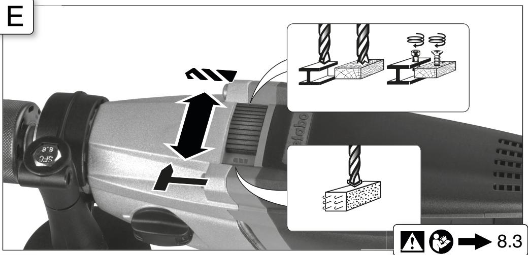
Normal drilling/Drill bit
Impact drilling
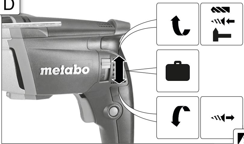
Movement direction
Driving screws/Screw
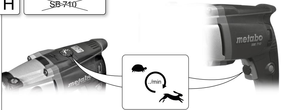
Slow
Fast
Thread tapping/Thread tapper
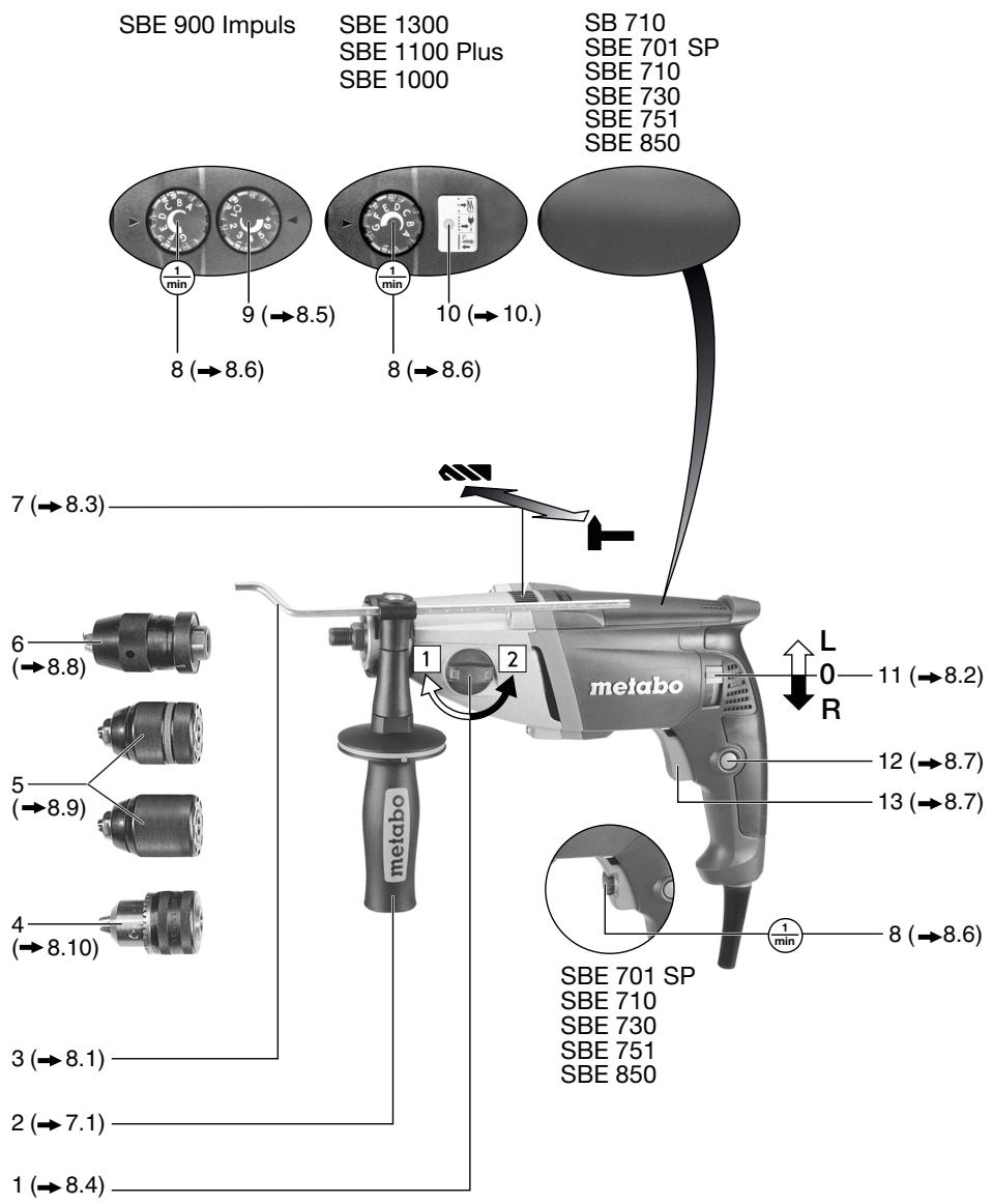
6. Overview

Fig. A
1 Thumb-wheel for gear selection
2 Additional handle/Additional handle with vibration damping *
3 Depth stop
4 Geared chuck *
5 Futuro Plus keyless chuck
6 Futuro Top keyless chuck *
7 Sliding switch (normal drilling/impact drilling)
8 Speed preselection wheel *
9 Setting wheel for torque control and impulse function *
10 Electronic signal indicator
11 Rotation selector switch *
12 Lock button for continuous activation
13 Trigger
depending on model
7. Initial Operation

Before plugging in the device, check to see that the rated mains voltage and mains
frequency, as specified on the rating label, match your power supply.

To guarantee secure purchase of the chuck: After initial drilling (clockwise), use a screw to firmly tighten the safety screw inside the chuck (if available/depending on the model).
THE SAFETY SCREW HAS A LEFT-HANDED THREAD!
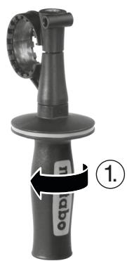
7.1 Fitting the additional handle (2) Fig. B

For safety reasons, always use the additional handle supplied.
Tighten the additional handle firmly by turning it.
8. Use
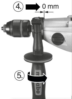
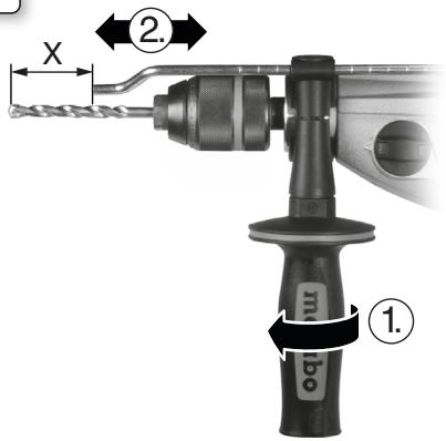
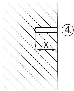
8.1 Setting depth stop Fig. C
8.2 Setting direction of rotation, transporting safety device (switch-on lock) Fig. D
Do not activate the rotation selector switch (11) unless the motor has completely stopped.
8.3 Setting for normal drilling, impact drilling Fig. E
Impact drilling and normal drilling only in a clockwise direction.
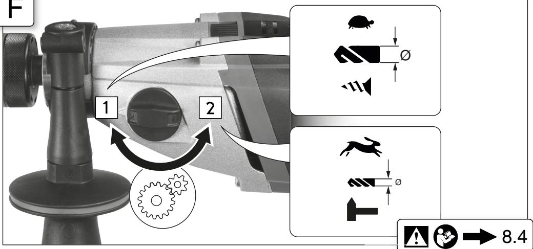
8.4 Selecting gear Fig.F
! Change thumbwheel (1) only when the machine is in the process of running down (briefly switch it on and off).
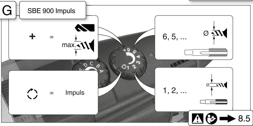
8.5 Setting torque control, impulse function Fig. G
Position 1-6: The motor comes to a complete stop when the preselected torque is reached.
1 = low torque
6 = high torque
+ = no torque control (max. torque, for drilling)
impulse function switched on constantly (to facilitate tightening and releasing of screws that are tight even when the screw heads are damaged. To enable clean drilling without centre punching in tiles, aluminium or other materials).
8.6 Preselecting rotational speed Fig. H See the table for recommended rotational speeds for drilling.
8.7 Switching On and Off
Switching on, rotational speed Fig. A: Press the trigger (13).
Release the trigger to switch off.
Continuous operation Fig. A: With the trigger (13) pressed, push in the locking button (12) and release the trigger. Press and release the trigger (13) again to switch off.
In continuous operation, the machine continues running if it is forced out of your hands. Therefore, always hold the machine with both hands using the handles provided, stand in a safe position and concentrate.
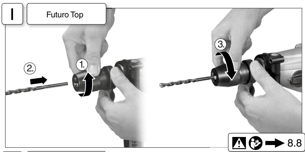
8.8 Tool change, Futuro Top keyless chuck (6) Fig.1
Clamp the tool by turning the sleeve firmly to its stop.
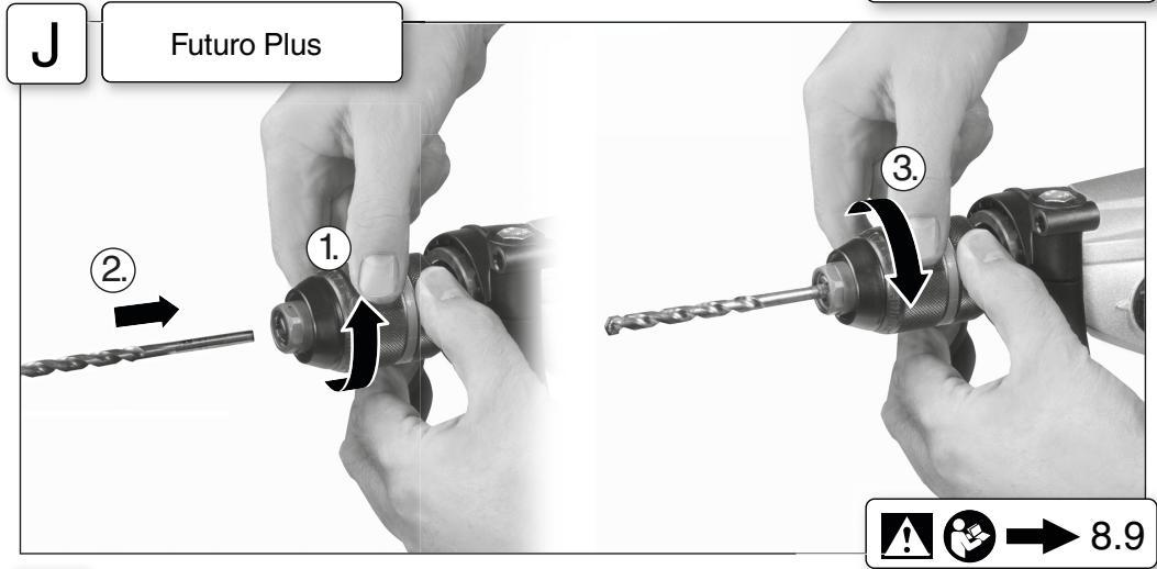
8.9 Tool change, Plus (5) keyless chuck Fig.J
The ratchet sound which can possibly be heard after opening the drill chuck is functional and is switched off by a reverse rotation of the sleeve.
If the chuck is very tightly closed: Firmly grip the chuck with an open-end spanner at the chuck head and firmly turn the sleeve in the direction of the arrow -1.
Clamping the tool
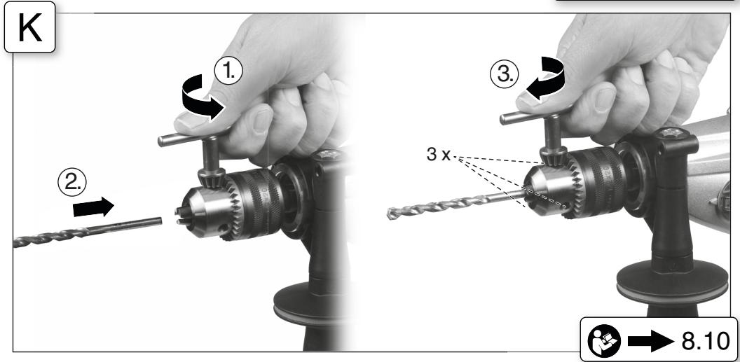
8.10 Tool change, geared chuck (4) Fig. K
- Insert the tool -2- as far as possible.
- Using one hand, hold the retainer ring securely (depending on fittings).
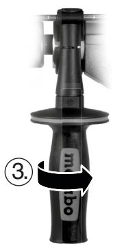
- Turn sleeve in direction -3- until the noticeable mechanical resistance has been overcome.
- Caution! The tool is not yet fully tightened! Keep turning the sleeve (it must "click" when turning) until it cannot be turned any further - only now is the tool safely clamped.
With a soft tool shank, retightening may be required after a short period of operation.
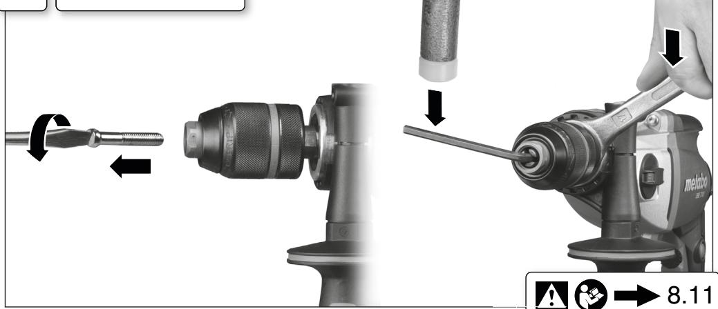
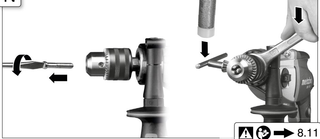
8.11 Unscrew the chuck (when driving screws without the chuck or for use with attachments) Fig. L, M, or N
Note for Fig. M, N: Release by tapping lightly with a rubber hammer, as shown, and unscrew.
Note: If a bit clamping bush (order no. 6.31281) is attached, the screwdriver bit inserted in the hexagon socket of the spindle is held in place.
9. Cleaning, Maintenance
Keyless chuck cleaning:
After prolonged use hold the chuck vertically, with the opening facing down, and fully open and close it several times. The dust collected falls from the opening. The application of cleaning spray to the jaws and jaw openings at regular intervals is recommended.
10. Troubleshooting
Electronic signal display (10):
Rapid flashing - restart protection
(SBE 1000, SBE 1100 Plus)
When power is restored after a power failure, the machine - which is still switched on - will not start for safety reasons. Switch machine on and off again.
Slow flashing - carbon brushes worn (SBE 1100 Plus, SBE 1300)
The carbon brushes are almost completely worn. If the brushes are completely worn, the machine switches off automatically. Have the brushes replaced by an authorized service centre.
Permanently lit - overload (SBE 1100 Plus)
If the machine is subject to long periods of continuous overloading, the power input of the machine is limited. This prevents the further unauthorized heating of the motor.
11. Accessories
Use only genuine Metabo accessories.
Use only accessories which fulfil the requirements and specifications listed in these operating instructions.
Fit accessories securely. Secure the machine if it is operated in a bracket. Loss of control can cause personal injury.
For a complete range of accessories, see www.metabo.com or the main catalogue.
12. Repairs
Repairs to electrical tools must be carried out by qualified electricians ONLY!
If you have Metabo electrical tools that require repairs, please contact your Metabo service centre. For addresses see www.metabo.com.
You can download spare parts lists from www.metabo.com.
13. Environmental Protection
Observe national regulations on environmentally compatible disposal and on the recycling of disused machines, packaging and accessories.
Only for EU countries: Never dispose of power tools in your household waste! In accordance with European Guideline 2002/96/EC on used electronic and electric equipment and its implementation in national legal systems, used power tools must be collected separately and handed in for environmentally compatible recycling.
14. Technical Specifications
Fig. O. We reserve the right to make technical improvements.
P1 = Rated input
P2 =Power output
n1 =No-load speed
n2* =Load speed
max. dia. =Max. solid drill diameter
s max = Max.impact rate
b =Chuck capacity
G =Spindle thread
H =Spindle with hexagon socket
m =Weight
D = D=Collardiameter
Measured values determined in conformity with EN 60745.
Machine in protection class II
Alternating current
The technical specifications quoted are subject to tolerances (in compliance with the relevant valid standards).
- Energy-rich, high-frequency interference can cause fluctuations in speed. The fluctuations disappear, however, as soon as the interference fades away.

Emission values
Using these values, you can estimate the emissions from this power tool and compare these with the values emitted by other power tools. The actual values may be higher or lower, depending on the particular application and the condition of the tool or power tool. In estimating the values, you should also include work breaks and periods of low use. Based on the estimated emission values, specify protective measures for the user - for example, any organisational steps that must be put in place.
Vibration total value (vector sum of three directions) determined in accordance with EN 60745:
a_h, ID = Vibration emission value (impact drilling into concrete)
a_h,D =Vibration emission value (drilling into metal)
Typical A-effective perceived sound levels:
LpA =Sound pressure level
Allumage permanent - surcharge (SBE 1100 Plus)
H =Broche a six pans creux
m = Poids
D =Diametre du collet
K_h,1D, K_h,D = Incertitude (vibration)
a_h, ID = vibrationsemissionsvärde (slagbörning i betong)
a_h,D = Vibrationsemissionsvärde (börning i metall)
K_h,1D, K_h,D = onoggrannhet (vibrationer)
Normal, A-viktad lijnivá:
LpA =Ljudtrycksnivá
LWA =Ijudeffektniva
K_D A K_WA = Os akerhet

Använd hörsselydd!
Maks. = Maksimal bore diameter
Reservedelslicer kan downloads pa www.metabo.com.
13. Miljobeskyttelse
a_h,D = Vibrationsemission (boring i metal)
K_h,1D, K_h,D = Usikkerhed (vibration)
IpepeBbIIOJIHeHnEMKaHnx-Ⅱ60pa6o nO peryI IIOBpE NII TexHnuecKOMy OBCJyHXBaHnIO IHCTpyMeHTa BbIHmMaTe BnIKy CeTeBOrO Ka6eJIa n3 p03eTkn.
HeOnyckaTe HenpeHamepeHHoro nycka: BcERdA CHIMAte 6bOKIOPOBHy C bIKIIOuTeJ, ECIN BnHa 6bJa BbIHyTa I3 pO3eTKN HIn ECIN npOn3oWcI c6oB I NpOaue TOKa.
Y6eIHTecb (HaPnIMep, c NOMOJIbIO MetaJILOINCHaTeJI), YTO B TOM MecTe, rIe 6byT npON3BOITbCRApoTbI, He npoxoJr IHHN 3JeHtPo-, BODo- Hra3OchA6HeHH.
06pa6aTbIbAemblteJeTaHnHe6oJbUoro pa3Mepa doJIHHbI bItb 3aΦHKuPOBaHbI (HaNPUMep, 3aKaTbIB TNCkax HIN 3aKpePJIeHbI Ha pa6OcEM CTOJIe C NOMOUsB OCTpy6UnH) TaHIM o6pa3OM, YTObI pR cBepLeHn OHn He 6bJI3 aXBaueHbI CBeplOM.
He npikacaiTecb K BpaaioiEmyca HnctpyMeHTy!YdaJIrTe ONIJKN I TOMy NpO6Hoe TOLbKO nocle nolHO OCTaHOBKn IHCTpyMeHTa.
PpeOxApaHnTeIbHaMyfTa Metabo S-automatic.
Pnp Cpa6aTbIbAHmN PpeOxApaHnTeIbHO MyfTbI
cpa3y Je OTKJIouHTe I NCTpymENT! B clyuae
3aKInIbHbAHH NIN 3aEJaHnI HNCTpyMeNTa
DbIraTeJb OCTaHaJIbNAeTCr. TeM He MeHee, B
CB8N C BO3MOKhbIM BO3HNKHOBEHMe OTdauN
Pnp pa6oTe Bcerda DeepKHe I NCHpymENT DByMRA
pyKaMn 3a pyKoRTKn, pRINHMaTe BoJe e yCTOn
YHBOE POLOJHEn He 6yBtBe BHMaTeJIbHbI pRn
BbINOJIHeHN pa6oTbl.
He nOJIb3yIe npEdoXpaHInTeJbHyo MyfTy Metabo S-automatic dIra orpaHnueHn KpyTaeero MOMeHTa.
Co6IIOJaIte OCTOPOJOHOCbI npn JEcTcKOM 3aBOp aBaHNH IyPyNOB (3aBOpaUHbAHne IypyNob C MeTpIeCKoI INI DIOHMoB pe3b6oB B CTaJIb)! FIOBHa IyPyaMoJET 6bITb COPBaHa NIN Ha pyKoRTHe MOYr BO3HNHHTy BbICOKHe peaKTHBhIE KpyTAUINE MOMHTbl.
Пьль, ВОЗнkaюшая рпообрабOTе MaTeри- алов, COdeржаши CBиNeц, HeKOTOpbIX BИДОВ dpeBecInHbI, МИнераши BOMeTЛПО, MOJeT ppeD- ctaJIbTb COsoBOnаСоHCTb ДЯг 3ДОРБь. Вдьхане чаNTи таКои пыл Илк ONТаKT C HeN MOJeT cStaTb PrnUHNo NOЯВLEHnA JAnlePrrHc- chen peakun H/INl 3abOleBaHnД bIXaTeIbHbIX nyTe.
HeKToOpBle BnDbIbIiN (HaNPmEep, Nblb, Bo3HnKaUo7aŋ pni o6pAbOTke Dya 6n i6yka) CunTaTOc KaHCpeOReHHbIMn, OOCeHNo B KOMbHaCN C DonOJIHNTeJbHbIMn MaTePnaIamM, McNoJIb3Ye
MbIMIДЯOBpa6OTKIN DpeBecHbI (COJINxPOMOBO KNCLOTb, cpeDCTBa3aHTNbI DpeBecHbI).OBpa6OTKa MaTePnaIOB CoepKeHaHnem ac6eCTa DOJIKNBa BIVoJIHbTcBcT OToBkO CNEuaJIncTAM.
-ПОВЗМоЖнOCTHNИСПОЛБ3уTE NOДХОДУПИ NBJIeOTcAcbIBAIOUПИ anPapat.
-Обеспун Te xopoшую BeHTnlaцию pa6ouch 30Hbl.
- PekomeHnyetcnaeBaTaBpeCnnpaTopcФиltpomKlaccaP2.
Co6JIIOJaIe Te DeIcTByUOuIe HaUIOHaJIbHbIe npEIIncAHnI NO o6paOtKe MaTePnaIob.
5. PucyHKn
PncyHn paCnoJIOxeHb I HauaIe pyKOBoDCTBa nO 3KcIpyTaUIN.
IorcheHnKHCNoJIb3yEmbIM Cnmbolam:

CbePJIeHne/CBepIIO
Udaphoe cBepJIeHne
HaprabJIeHne DmJKeHnIa
3abopauHbAHne uypynoB/uypyn
MeDJIeHNo
BbICTPO
Pe3b6oHaape3aHne/MeTnK
6. 063op

Pnc.A
1 PpeKluOaTeIb IyBb6opa ChOpocTn
2Дононтельная руковта/донолпеньная руковда с raшенивбраци*
3OrpaHnHTeIbIy6HbIcBepHeHn
4 NatpoH c 3y6aTbIM BEHcOm
5БыстpoЗжИМнй naTpOH Futuro Plus*
6Быстрозамногиатрон Futuro Top*
7Переклочаель (севелянe/ударhoe CBepelene)
8 YctaHOBOUHoe KOleCnKO dI pypeBapuTeIbHOrO Bbl60paYacTObI BpaSeHnra
9 YctaHOBOUHOOKeLOeICHOДЯ NaCTPOIKNOrpaHUNHeHKn KpyTaeOro MOMeHTa N BKHIOUeHnNmPNUbCHOrOpeXHIMa
10 ΘλeKτροHHbI CnHαJIbHbI INHДИKaTOp *
11 PpeekluoyateIb HappaBHeHn BpaueHn*
12 KhoNka-ФнcaTopДЯнрepbIBHoro peKIMpa6oTbI
13 HaxmnoH nepeKIOUaTeIb
* B 3aBnCmOCTN OT KOMJIeKtauIN
7. BbOaB 3HcπLyatauHIO

Ipeed BBODOMB 3KcNlyaatauHIO npOBepbTe COOTBETCTBNE CETeBOrHO HnprJKeHnri N
YacTObI, Yka3aHHbIX Ha 3aBOcKoT Ta6JIuHKe, NapamETpam Cetn 3JIeKTpONtAHn.

Дяобсpeонинаджнoctифкcaи CBepnIbHOrO natoHa: nocle nepBoro
CbepeHnna (npaBoe BpaueHne) 3aTHNte C nOMOsbIO OTBepTKN CTONOpHbIN BnHT BHyTpN
NaTPOHa (B CJIyuae HaNUHry/B 3aBNCIMOCTN OT MoJeLi). JeBaJ pe3b6a!
7.1 YcTaHOBbA DOIOJHHTeJIbHOu pyKoTTHN (2) pnc.B
I3 coo6paJHe 6eONaCHOCTn BCerda npIMeHJIte DoOnJIHHTeJIbHyU pyKoRTHy, BXOJaIyO B KOMJIeHT NOCTaIKN.
Плотно 3атянite ДОпOLHINTEЛьнуpyКоТКу nyTem ee 3abOpaunBaHnru.
8. энспунатусян
8.1 PerylnpoBbA orpaHnHTeIaIy6HbI pnc.C
8.2 PerylnpOBKa HnpaBLeHnBa BpaSeHnA, yctaHObKa 6LoHKoPbHNДЯ TpaHcnpTOpOBKn (6LoKInpOBKa BkIIOHeHnA)
Pnc.D
HauimaiTepeKluOateJIb HapabLeHnIBApaUeHI (10)ToIbKO npHepa6oTaIOeM 3JIeKTOPOBUNAteJIe.
8.3 PerynpoBbA peHMa o6bIuHoro/ydapHoro cBepHeHra pnc.E
CbepeHne u yapHoe cBepeHne npo3BO- Dte ToIbKO pnpaBOM BpaueHn.
8.4 BbI6Op chOpocTn pnc.F
! Npeekluoyehne nepekluoyaTeIe (1) BblonJIHnIe ToJbHo BO BPMePAoBtI INCHTpYMeHTA NO INEPUIN NocIE BblKluoyehne (HaKOPOITKe BPEM BBLIOUHTe/BblIKLUOHTe).
8.5 PerylnpoBHa orpaHnueHn KpyTaeero MOMeHTa, mNpybChOro peHmTa pnc.G
PonokHeHne 1-6: npn doctnKehnn npedyctaHoBLeHHoro KpyTaeo MOMeHTa 3JeKTPoDBnAratBeIbOCTaHaJIbAeTcR.
1 = Hn3Knn KpyTAAm MOMENT
6 = BBICOKH KpyTAAH MOMENT
- =6e3 orpaHnUeHnKpyTuaero MOMeHTa (MaHC.KpyTuaHIMOMeHT,ДЯ CBepJIeHnA)
=IMNpybcHbIpeJHKIM BKLIOUeH NOCTOHNO (ДЯЛERKORO 3aBOPaUHBAHn N bIBOPaHnBAHnПLOTHO CnDAJIUX WUPyOB,ДаЖe NOBPEJxDEHNbIX;ДЯпОТВРаЧЕнnyBOda CBepla B MOMENT HauJaLc CBepLeHnR 6e3 KepeHnI prN CBepLeHnIN B KepaMHeCKOJI PLITHE,aJIOMNHHeBbIX INI Dpyrnx MaTepeHaJax.)
8.6 Празустанова чаctOTы Врашени →Pис.H
PeKOMeHdyemble 3HaueHnHa cactOTbI BpaueHnJaIcBpeHn,CM.Ta6JI.
8.7 BhJIOUeHne/BbIKJIOUeHne
BhloueHne, yactota BpaueHn pnc. A: haxmnte nepekliouaTeIb (13).
ДяВыкюченOTпuctteнхимниpekeKIO-уATEЛ.
PeknH HnepepbIBHO pa6oTbI pnc.A: npn HaKaTOM nepeKIOUaTeIe (13) HaKMITE KHOINKYΦHKaTOp (12) n OTNCTHe NaHMHOI nepeKIOUaTeIb.ДЯ BbIKIOUeHnHaKMITE HaKMHOI nepeKIOUaTeIb (13) eue pa3, a 3aTeM OTNCTnte erO.

B HenpepbibHom peKIMe INCTpymEnTpoJnKaet paBoTaB, daKe eCIn OH
BbIPBcTeN3pyKn.10eTOMy BceTaHaDeEHHo ydepHnBaTe 3eHTPOINHCTPymeHT DByMaPyKaMn 3a pyKoTkn,3aHmMaTe yCTOuHBOe NOLOXHeHne nCKOHcTeHTpPyTe BCE BHMaHHe Ha BbIOJIHeMOn pa6Ote.
8.8 CmeHa pa6oOerHOHCTpyMeHTa/6bICTpo-3aHHMHOI naTPOH Futuro Top (6)
PNC.1
3aJHIM INCTpyMeHTa: C yCNIJIeM IOBepHITe TINb3y Do yNopa.
8.9 Cmeha pa6oeryo HnHCTpyMeHa/6bIcTpo-3aHMMHO nATpon Plus (5) pnc.J
NotpecknBaHne, KOtOpoe MOKHe 6bItb CbIuHo
NocLe OTKpBtTH NaTPOHa (ObycNoBJeHO
KOHCTpyKUne), yCTpaHReTcBApuCheHEm FInb3bl
B nPOTNBONIOJXHOM HAnpabJIeHH.
EcII naTPOH 3aTAYHT CNIUHKOM CNIbHO: 3aXMMTE CBepINbHbN nATPOTH RAeCHbIM KINOCHOM 3a ROJIOBKY naTPOHa N NOBEPHNTe C yCINHeM TINb3y HnapBaJIeHN CTpeKN (-1-).
3aKpeIJIeHne IHHCTpymeNTa:
- BCTaBtpe pa6oyn HnctpymehT -2- KaK MoJHNO rny6ke.
- YdepeKnBaOJHOHpyKoN CTOpOpHoe KOJIbIcO (B 3aBNCIMOCTOn OT KOMJIeKtAun),
- noBOPaUHbAaTe rHnIb3y B HAnpBaJIeHN cTpeIKN 3-, nOka He 6byet peoDoJeHO OuTyTMoe MekaHueCKeO cOpOTnIBHeNIE.
-BHnMaHHe!Pa6OuH NHCtPymeHT B daHHbIM OMeHTe ehe He 3aHaT!IpoDoJIxHaJTe BpaUeHne C cyuInem (pNn 3OTm DOJIxHbI 6bItb CblIWHbI eLChN) do yOpna-TOIbHO Tepeb INHCTPymeHT 3aKaT HADExHIO.
NHCTPymETC XBOCTOBHOM I3 MMRHO MaTeprnla Heo6xOdIMO NOJtTgRbTaB TocSe HneIpoJoJIKIn-TeJIbHOrO BpeMeHN CBepJIeHNA.
8.10 CmeHa pa6oOerO HnHcTpymeHTa/NaTPOH c 3y6aTbIM BeHcOM (4) pnc.K
8.11 OtBepHnte cBepnIbHbI nAtpoN (JIA naBopaunBaHn 6e3 CBePnIbHoro naTPOHa HIN IaN IcNoJIb3OBAHnC hacaDnAMn) PnC.L.M.HN N
YkaaHne IJIpa nC.M.N:ocna6bTeJeRKM UnapompeHHOBOROMJMOIOTKa(CM.PnC.)INOTBHN-TNTe.
Yka3aHn: npu yCTaHOBJeHHo3 3aJHMHOB BTVJKe 1n8 6nt (NqIy3aKa3a6.31281) OThBeTouhbl 6bT BCTaBJAETcB WueCTIrpaHNNk UwHnDEJI.
9. Ouinchka, Texhnyechoe 06cIyJHHBaHne
OuHCTKa 6bICTpO3aJHMHO CBePJIbHOro nATPOHa; nocLe dIITeJIbHO 3KcNpyAtaUm yCTaHOBHTe CBEPJIbHbIy naTPOH BePTIKaJIbHO OTBepCTnEM BHN3 HECHO bpa3 POJHOCtBbO OTKpOHTe 3aKpOHTeero.HaKONIBWJaCRA nbIb 6yDet BBICblNaTbCSnOTBepCTnE. PeKOMEnyETcpeYJrpho HAHOCTNb YCHSTCe cpeCTBO a3po30JIbHO yNAKOBHe Ha 3aJHMBlte KJUaNH N B OTBepCTnMeJdY 3aJHMbIMn KJNaChAMi.
10. YctpaHHeHne HEnCnpaBHOcTei
3JeIeHTpOHHbI CNrHaJIbHbI INHdINHaTOp (10)
Yactoe MrraHne -3aUHTa OT NOBtOPHOpycka (SBE 1000, SBE 1100 Plus)
ПрвВОЗБHOBЛECHИ NOДачи элКТРОПТАнЯ NOCLE OEG OTKHIOCHENBA CEJIAX 6E3ONaCHOCTN He Ipon3BOJNTCABTOMATUeCKH NyCK BKLIQUEH HORO B Cetb INHCTPymeHTA. BbIKLIOChTE n CHOBA BKHIOHTe INHCTPymeHT.
PeHKe MInaHHe - H3Hoc yToJIbHbIX UeTOK (SBE 1100 Plus, SBE 1300)
PpOn3OoJen NOHTI NOHbI N3HOC yOrNoBbIX 电TOK.PnN3HOceYrOJIbHbIX TcTOK INCTPYMeNT ABOTOMaTHUeCKN OTKIOUcAETC.BIINOJIhNTe 3aMeHy rOJIbHbIX tEOK BCEPBICHO CnyJ6e.
HenpepbIbHoe ropeHne - neperpy3ka (SBE 1100 Plus)
B clyae dIITeIbHnI nepepy3Kn INHCTpymeHTa ORpaHNHVAEETC NOTPeJIaERMaJ MOUHOCb, YTO n03BOJAErN36eKaTb DaJIbHeJWeO HeONyCTmoro HarpBeA 3JeKToPDBnATeJIa.
11.Пинадлжноctи
IcnoIb3yTe ToIbKO opnHaNbHbIe npHaadJeK-HocTn Metabo.
IcnoIb3yIteToIbHO Te npHaIeJHIOCTN, KOtOpIbe OTBeaIOT Tpe6ObaHnI NnapaMeTpam, nepeuCJIeHHbIM B daHHom pyKOBoDCTBE NO 3KcNlYaTAtzU.
HaJeKHO PhIKCnpyTe npHaJNeKHoCTn. Ppi 3KnIpyataunn 3eKTPoHnCTpymeHTa B depKaTe: HaJeKHO 3akpenITE 3eKTPoHnCTpymeHT. IopePra KOHTpOJa HAd 3eKTPoHnCTpymeHTom n HacaJKO MoKeT cTaTB pNCHIO nOlyceHn TpaBM.
Полный ACCOPTIMENT рпнадлжноcte symontte Ha caite WWW.metabo.com ИИВ rlabom KataJore.
12. PemOHr
K pemohrty 3JIeKTPoHnCTpyMEnTa dOnyckAOTcT ToIbKO KBAJIuΦiUncpOBaHbIe CneuaJInCTbI-JIeK- TpknI
ДлpeMoHTa элктponHCTpymEnTa pOOn3B0DcTba Metabo obpaauaiTeCb B 6bInkaiuWee npEdCTaBnTeJIbCTBO Metabo.Adpeca cm. Ha caIte www.metabo.com.
Cπικη 3aŋvaCTe moKHo cKaaTa b Ha www.metabo.com.
13. 3aunta okpykaoue cpebl
BbInolHnTe HaNHOHaIbNbIe npaBnla yTINIm-3aunn n nepebaOToK OTCnykHBwero INCTpyMeHTa,ynakOBn o pinnahdJIeXHNOCTei.

TolbkoДЯн STРAN EC: He BbIbpaBbAte TJIeTPOHCTPymENT BMcTe C bSbTOBbIMOn OTXoDAMn! CorlaNo DmpeKtNBe 2002/96/
EG 6b yTnIIN3aunu cTapbIX 3JIeKTPoPnp6OpOB u 3JIeKTPoHORO 6OBpyUOBAHn I COOTBETCTBYUHN HAUNOHALbHbIM HOPMAM 6bIBUNe B yNtPO6JIeHN 3JIeKTPoPnp6OpBu IN 3JIeKTPoINHCTpymENTbl NOJENKaT pa3dJeBHOY TnIN3aunu C ceJIbIOHX nocLeDyUoSeE 3KOLOrnueCeKn 6BeONaCHO nepepa60THN.
14. TexHnueechne xapaHTepnCTnHN
Pnc. O.Bo3MOxHbI N3MeHeHnB C8r3n CycOBepseHcTBoBaHnEm N3dJIIn.
P1 = HOMINaJIbHaЯ MOUHOCtB
P2 =BbIXOHaRA MOUHOCTb
n1* =yactotaBpaueHn6e3Harpy3KN
n² =YacToTaBpaueHnIoNHaRpy3KoI
MAKc=MaKcImMaJIbHbI dHaMeTp CBePJa
S MaKc. =MaKcHmJaBHa JaCTota yJaPoB
G =pe3b6a CBePnIbHOro ⅦnHdJIa
H =CBePnIbHbI WIIINHDeJIb C BHyTpeHHIM WeCTNIRpaHHIKOM
m = macca
D =Диametршейнзхима
Pe3yIbTaTbI N3MepeHn IOnyuYeHb B COOTBeCTBn CO CTaHapTom EN 60745.
3JIeKTPoINHCTpyMeHT Klacca 3aunTbI II
Nepemehhbl TOK
Ha kya3aahhhhe TexHnueckne XapakTepeNCTNKpacnpoctpaHHOTc DonyCKn, npdeYcmOTpeHHbIeDeiCETBvIOUIMN CTaHdAptAMn.
*MouhBle BbICOKOACTOTHbLE NOMEXH MOryT BbI3BaTb KOJIe6aHnHaCTOTb I BpaueHn. Pn3 a3TuXaHNIOxEMK OJIe6aHnI npEkauaTOcT.

3haeHnIyMa n Bn6paun
3TN 3NaHEnnIO3BOJIAOT OeHNBaTb N CpaB
HnBaTb Wm N Bn6paCIO, CO3daBaemIe npi
paOte pa3JIuHbIX 3JeKTPoHNCTPymeHTOB. B
3aBNCIMoCTN OT yCLOBNI 3KcNlPyATAcIN, COCTO
Hnra 3JeKTPoHNCTpyMeNTa nPi naOboUHX
(CMeHHbIX) HnCTpyMEnTOB 0aKTnueckAn Harpy3Ha
MOKeT 6bITb BblSe Nn HnKe. Pn OnpeDeleHn
pIpMepHOrO yPoBHg N Mya M INbPaacn yuHTbI
BaTe nepePBbIb B paOte N a3aBl pa6oTBc NOHn
HeHHo (WMoBOI) Harpy3Kn. OPeJeNeIte
pepeHeB opraHn3aOnOHbIX MEP no 3aUnITE
IIOJIb3OBATeJIa C UyeTOM TEX IIN INHbIX 3HaueHIn NUyMa N B6paun.
CymmaHoe 3HaueHe BnBpaun (BeKToPna Cymma Tpex HnapBaIeHn) paCCnTbIaEaTeCB COOTBCTBN co CTaNdApTOM EN 60745:
ah, ID 3NaueHne BV6paun (yadpoe CbepeJIeNE B 6eTOHe)
a_h,D = 3NaueHneBv6paunn(CBepJIeHneB mTaJIne)
Kh,ID,Kh,D=Ko3ΦΦmUeHT nOpeuHocTn (Bn6paun)
YpOBeHbIyMa IOMeTOnyA:
LpA =ypoBHeH 3BykoBOrO daBHeHn
LWA =ypoBHeH 3ByKOBOMOuHOCTH
KpA, KWA= KOaΦΦnUeH NTorpeuHocTN
HaedeBaIte 3aunTHbIe HayuHnKn!
EAC
HOpMaunIy nokynateIa:
CeptnΦnkat COOTBETCTBnA:
CepTHnΦHKaT COOTBeTCTBnR: Nc TC BY/112 02.01. 003 03389, cpoK DeiCTBnR c 21.01.2014 no 20.01.2019 r., BbIaH Pecny6bnKaHcNIM yHITapHBIM IpeDnPnAHTmE «BeLOpYCSnR roCy- dApCTBeHHbI INCTNTyT MeTpOJorN»; Pecny- 6bnKa BeLApCy b2, 20053, r.MInhck, CtapOBuHeHcN K TpaKT, 93; TeI.: +375172335501; aTTeTeTaT aKKPeDnItauN: BY/112 003.02 ot 15.10.1999.
CtpaHa n3roTOBLeHnIy: TepMaHnIy
ПразиЗВОДИТЕЛь (3aBOД-и3rTOBOTeNTeЛb):
"Metabowerke GmbH".
Metaboallee 1,
D-72622 Nuertingen, TepmaHHa
HmnpTeB Poccn:
OOO "MeTa6o EBya3n"
Poccn,127273,MochBa
yI. Bepe3oBa aIJIe, I5 a, cTp 7, oΦnc 106 TEL.: +7 495 980 78 41
CpOK cnJyK6bl INHCTpyMeHTa: 5IeT c DaTbI n3rTOBJIeHHIA

- A
- Original instructions
- Declaration of Conformity
- Specified Use
- General Safety Instructions
- Keep all safety instructions and information for future reference.
- Special Safety Instructions
- Wear ear protectors when impact drilling.
- Figures
- Symbol explanation:
- Overview
- Fig. A
- Initial Operation
- Use
- Switching On and Off
- Unscrew the chuck (when driving screws without the chuck or for use with attachments) → Fig. L, M, or N
- Cleaning, Maintenance
- Troubleshooting
- Accessories
- Repairs
- Environmental Protection
- Technical Specifications
- Emission values
- Använd hörsselydd!
- Miljobeskyttelse
- PucyHKn
- IorcheHnKHCNoJIb3yEmbIM Cnmbolam:
- 063op
- BbOaB 3HcπLyatauHIO
- YcTaHOBbA DOIOJHHTeJIbHOu pyKoTTHN (2) → pnc.B
- энспунатусян
- PerylnpoBbA orpaHnHTeIaIy6HbI → pnc.C
- PerylnpOBKa HnpaBLeHnBa BpaSeHnA, yctaHObKa 6LoHKoPbHNДЯ TpaHcnpTOpOBKn (6LoKInpOBKa BkIIOHeHnA)
- PerynpoBbA peHMa o6bIuHoro/ydapHoro cBepHeHra → pnc.E
- BbI6Op chOpocTn → pnc.F
- PerylnpoBHa orpaHnueHn KpyTaeero MOMeHTa, mNpybChOro peHmTa → pnc.G
- Празустанова чаctOTы Врашени →Pис.H
- BhJIOUeHne/BbIKJIOUeHne
- CmeHa pa6oOerHOHCTpyMeHTa/6bICTpo-3aHHMHOI naTPOH Futuro Top (6)
- Cmeha pa6oeryo HnHCTpyMeHa/6bIcTpo-3aHMMHO nATpon Plus (5) → pnc.J
- CmeHa pa6oOerO HnHcTpymeHTa/NaTPOH c 3y6aTbIM BeHcOM (4) → pnc.K
- OtBepHnte cBepnIbHbI nAtpoN (JIA naBopaunBaHn 6e3 CBePnIbHoro naTPOHa HIN IaN IcNoJIb3OBAHnC hacaDnAMn) PnC.L.M.HN N
- Ouinchka, Texhnyechoe 06cIyJHHBaHne
- YctpaHHeHne HEnCnpaBHOcTei
- 11.Пинадлжноctи
- PemOHr
- 3aunta okpykaoue cpebl
- TexHnueechne xapaHTepnCTnHN
- 3haeHnIyMa n Bn6paun
- EAC
- HOpMaunIy nokynateIa:
Brand : METABO
Model : SB 710 SBE 701 SP SBE 710 SBE 730 SBE 751 SBE 850 SBE 900 Impuls SBE 1000 SBE 1100 Plus SBE 1300
Category : Hammer drill