
CSE 2040 - Electric chainsaw MC CULLOCH - Free user manual and instructions
Find the device manual for free CSE 2040 MC CULLOCH in PDF.
Download the instructions for your Electric chainsaw in PDF format for free! Find your manual CSE 2040 - MC CULLOCH and take your electronic device back in hand. On this page are published all the documents necessary for the use of your device. CSE 2040 by MC CULLOCH.
USER MANUAL CSE 2040 MC CULLOCH
GB Original Instructions HR Originalne upute EE Algsed juhised Read before use and retain for future reference
WICHTIGE INFORMATIONEN Rear handle Rear hand guard Front handle Front hand guard/chain brake lever Chain tensioner outer knob Chain tensioner screw Chain tensioner pin Oil tank cap Oil tank inspection gauge Air vents Cable Manual Switch Switch block Chain Drive tooth Cutting link Cutting depth gauge 8, 9,14 Cutting tooth Guide Bar Drive Sprocket Cover Drive Sprocket Chain catcher Bar retaining screw Bar retaining inner knob Bar retaining nut Nose sprocket Guard bar cover Spiked bumper Chain tensioner pin housing Lubrication hole Guide bar groove Spanner/screwdriver 6 10, 15 Example of identification label
Guaranteed sound power according to directive 2000/14/EC Class II tool CE marking of conformity Rated frequency Rated power Alternating current Rated voltage Type Product code Year of manufacture Maximum length of guide bar Manufacturer’s name and address Article number (Electric Chainsaw) Model Serial number ENGLISH - 1
B. SAFETY PRECAUTIONS
MEANING OF SYMBOLS
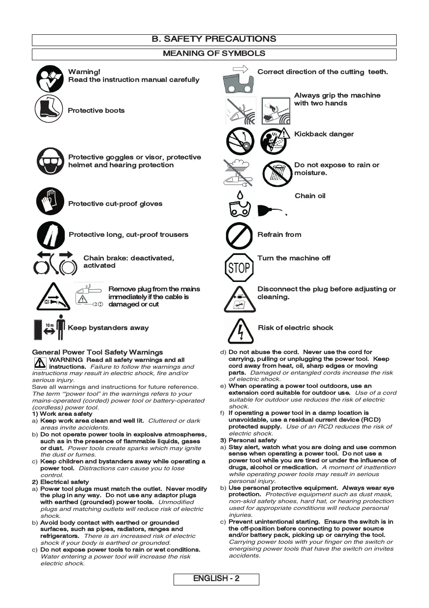
Warning! Read the instruction manual carefully Correct direction of the cutting teeth. Always grip the machine with two hands Protective boots Kickback danger Protective goggles or visor, protective helmet and hearing protection Do not expose to rain or moisture. Chain oil Protective cut-proof gloves Protective long, cut-proof trousers Refrain from Chain brake: deactivated, activated Turn the machine off Remove plug from the mains immediately if the cable is damaged or cut 10 m Keep bystanders away Risk of electric shock General Power Tool Safety Warnings WARNING Read all safety warnings and all instructions. Failure to follow the warnings and instructions may result in electric shock, fire and/or serious injury. Save all warnings and instructions for future reference. The term ‘“power tool” in the warnings refers to your mains-operated (corded) power tool or battery-operated (cordless) power tool.
1) Work area safety
a) Keep work area clean and well lit. areas invite accidents.
Do not operate power tools in explosive atmospheres, such as in the presence of flammable liquids, gases or dust. Power tools create sparks which may ignite Keep children and bystanders away while operating a power tool. Distractions can cause you to lose control.
2) Electrical safety
a) Power tool plugs must match the outlet. Never modify the plug in any way. Do not use any adaptor plugs with earthed (grounded) power tools. Unmodified plugs and matching outlets will reduce risk of electric shock.
Avoid body contact with earthed or grounded surfaces, such as pipes, radiators, ranges and refrigerators. There is an increased risk of electric shock if your body is earthed or grounded.
Do not abuse the cord. Never use the cord for carrying, pulling or unplugging the power tool. Keep cord away from heat, oil, sharp edges or moving parts. Damaged or entangled cords increase the risk
When operating a power tool outdoors, use an extension cord suitable for outdoor use. Use of a cord of electric shock. suitable for outdoor use reduces the risk of electric shock.
Cluttered or dark Disconnect the plug before adjusting or cleaning. Do not expose power tools to rain or wet conditions. Water entering a power tool will increase the risk electric shock. If operating a power tool in a damp location is unavoidable, use a residual current device (RCD) protected supply. Use of an RCD reduces the risk of electric shock.
3) Personal safety
a) Stay alert, watch what you are doing and use common sense when operating a power tool. Do not use a power tool while you are tired or under the influence of drugs, alcohol or medication. A moment of inattention while operating power tools may result in serious personal injury.
Use personal protective equipment. Always wear eye protection. Protective equipment such as dust mask, non-skid safety shoes, hard hat, or hearing protection used for appropriate conditions will reduce personal injuries.
Prevent unintentional starting. Ensure the switch is in the off-position before connecting to power source and/or battery pack, picking up or carrying the tool. Carrying power tools with your finger on the switch or energising power tools that have the switch on invites accidents. ENGLISH - 2
Remove any adjusting key or wrench before turning the power tool on. A wrench or a key left attached to a rotating part of the power tools may result in personal injury. ladders may cause a loss of balance or control of the chain saw.
Do not overreach. Keep proper footing and balance released the spring loaded limb may strike the operator and/or throw the chain saw out of control. at all times. This enables better control of the power tool in unexpected situations.
from moving parts. Loose clothes, jewellery or long hair can be caught in movingparts.
Dress properly. Do not wear loose clothing or jewellery. Keep your hair, clothing and gloves away If devices are provided for the connection of dust extraction and collection facilities, ensure these are connected and properly used. Use of dust collection can reduce dust-related hazards.
4) Power tool use and care
a) Do not force the power tool. Use the correct power tool for your application. The correct power tool will lubricated chain may either break or increase the chance for kickback. Keep handles dry, clean and free from oil and grease. Disconnect the plug from the power source and/or the battery pack from the power tool before making any adjustments, changing accessories, or storing power tools. Such preventive safety measures reduce the
Cut wood only. Do not use chain saw for purposes not intended. For example: do not use chain saw for cutting plastic, masonry or non-wood building materials. Use of the chain saw for operations Store idle power tools out of the reach of children and do not allow persons unfamiliar with the power tool or these instructions to operate the power tool. Power different than intended could result in a hazardous situation. Kickback may occur when the nose or tip of the guide bar touches an object, or when the wood closes in and pinches the saw chain in the cut. Tip contact in some cases may cause a sudden reverse reaction, kicking the guide bar up and back towards the operator. Pinching the saw chain along the top of the guide bar may push the guide bar rapidly back towards the operator. Either of these reactions may cause you to lose control of the saw which could result in serious personal injury. Do not rely exclusively upon the safety devises built into your saw. As a chain saw user, you should take several steps to keep your cutting jobs free from accident or injury. Kickback is a result of tool misuse and/or incorrect operating procedures or conditions and can be avoided by taking proper precautions as given below: Maintain power tools. Check for misalignment or binding of moving parts, breakage of parts and any other condition that may affect the power tool’s operation. If damaged, have the power tool repaired before use. Many accidents are caused by poorly Keep cutting tools sharp and clean. Properly maintained cutting tools with sharp cutting edges are less likely to bind and are easier to control. Use the power tool, accessories and tool bits etc. in accordance with these instructions, taking into account the working conditions and the work to be performed. Use of the power tool for operations different from those intended could result in a hazardous situation.
5. Service
a) Have your power tool serviced by a qualified repair person using only identical replacement parts. This
will ensure that the safety of the power tool is maintained. Chain saw safety warnings:
Keep all parts of the body away from the saw chain when the chain saw is operating. Before you start the chain saw, make sure the saw chain is not contacting anything. A moment of inattention while operating chain saws may cause entanglement of your clothing or body with the saw chain.
Always hold the chain saw with your right hand on the rear handle and your left hand on the front handle. Holding the chain saw with a reversed hand configuration increases the risk of personal injury and should never be done.
Hold the power tool by insulated gripping surfaces only, because the saw chain may contact hidden wiring or its own cord. Saw chains contacting a "live" wire may make exposed metal parts of the power tool "live" and could give the operator an electric shock.
Wear safety glasses and hearing protection. Further protective equipment for head, hands, legs and feet is recommended. Adequate protective clothing will reduce personal injury by flying debris or accidental contact with the saw chain. Do not operate a chain saw in a tree. Operation of chain saw while up a tree may result in personal injury. Always keep proper footing and operate the chain saw only when standing on fixed, secure and level surface. Slippery or unstable surfaces such as Greasy, oily handles are slippery causing loss of control. Causes and operator prevention of kickback: tools are dangerous in the hands of untrained users.
Follow instructions for lubricating, chain tensioning and changing accessories. Improperly tensioned or
risk of starting the power tool accidentally.
Carry the chain saw by the front handle with the chain saw switched off and away from your body. When transporting or storing the chain saw always fit the guide bar cover. Proper handling of the chain saw Do not use the power tool if the switch does not turn it on and off. Any power tool that cannot be controlled with the switch is dangerous and must be repaired.
Use extreme caution when cutting brush and saplings. The slender material may catch the saw chain and be whipped forward toward you or pull you off balance. will reduce the likelihood of accidental contact with the moving saw chain.
do the job better and safer at the rate for which it was designed.
When cutting a limb that is under tension be alert for spring back. When the tension in the wood fibres is Maintain a firm grip, with thumbs and fingers encircling the chain saw handles, with both hands on the saw and position your body and arm to allow you to resist kickback forces. Kickback forces can be controlled by the operator, if proper precautions are taken. Do not let go of the chain saw.
Do not overreach and do not cut above shoulder height. This helps prevent unintended tip contact and enables better control of the chain saw in unexpected situations. Only use replacement bars and chains specified by the manufacturer. Incorrect replacement bars and chains may cause chain breakage and/or kickback.
Follow the manufacturer’s sharpening and maintenance instructions for the saw chain. Decreasing the depth gauge height can lead to increased kickback. Additional Safety Recommendations
1. Manual use. All persons using this machine must
read the user manual completely with extreme care. The user manual must be included with the machine in the case of sale or loan to another person.
2. Precautions prior to machine use. Never permit this
machine to be used by any persons who are not perfectly familiar with the manual instructions. Inexperienced persons must follow a training period operating on a saw horse only.
3. Control checks. Check the machine with care before
use each time, especially if it has been subject to strong impact, or if it shows any signs of malfunction. Perform all operations described in the chapter “Maintenance & Storage – Before each use”. ENGLISH - 3 Repairs and Maintenance. All the machine parts that can be replaced personally, are clearly explained in the “Assembly / disassembly” instructions chapter. Where necessary, all other machine parts must be replaced exclusively by an Authorised Service Centre.
5. Clothing. (fig 4) When using this machine the user
must wear the following approved individual protective clothing : close-fitting protective clothing, safety boots with non-slip soles, crush-proof toe protectors and cut-proof protection, cut-proof vibration-proof gloves, protective goggles or safety visor, ear protection muffs and helmet (if there is any danger of falling objects).
6. Health precautions – Vibrations and Noise levels.
Avoid using the machine for long periods of time: the noise and vibrations can be dangerous causing irritation, stress, fatigue and hypacusia (hearing problems). Prolonged machine use exposes the user to vibrations that can generate “white finger phenomenon” (Raynaud’s Phenomenon), carpal tunnel syndrome and similar disturbances.
7. Health precautions – Chemical agents. Avoid all
chain oil contact with skin and eyes.
8. Health precautions - Heat. During use, sprocket and
chain reach very high temperatures, take care not to touch these parts while hot.
9. WARNING! This machine produces an
electromagnetic field during operation. This field may under some circumstances interfere with active or passive medical implants. To reduce the risk of serious or fatal injury, we recommend persons with medical implants to consult their physician and the medical implant manufacturer before operating this machine. Transport and storage precautions. (fig 12) Each time the work area is changed to another location, disconnect the machine from the mains supply and activate the chain brake lever. Mount the guide bar cover guard each time before transporting or storage. Always carry the machine by hand with the bar facing backwards, or when transporting the machine in a vehicle, always attach it securely to prevent damage. Kickback reaction. (fig 14) The kickback reaction consists of a violent upwards-reverse action of the bar towards the user. This generally occurs if the upper part of the bar nose (called the “kickback danger zone”) comes into contact with some object, or if the chain is blocked in the wood. Kickback can make the user loose control of the machine provoking dangerous and even fatal accidents. The chain brake lever and other safety devices are not sufficient to protect the user against injury: the user must be well aware of the conditions that can provoke the reaction, and prevent them by paying very close attention according to experience, together with prudent and correct machine handling (for example: never cut several branches at a time because this can cause accidental impact on the “kickback danger zone”
1. Never allow children or people unfamiliar with these
instructions to use the product. Local regulations may restrict the age of the operator.
2. Only use the product in the manner and for the
functions described in these instructions.
3. Check the whole work area carefully to check for any
danger source (e.g.: roads, paths, electric cables, dangerous trees, etc)
4. Keep all bystanders and animals well clear of the
work area (where necessary, fence off the area and use warning signs) at a minimum distance of 2.5 x the trunk height; in any case no less than ten metres.
5. The operator or user is responsible for accidents or
hazards occurring to other people or their property. Electrical safety
1. It is recommended that you use a Residual Current
Device (R.C.D.) with a tripping current of not more than 30mA. Even with a R.C.D. installed 100% safety cannot be guaranteed and safe working practice must be followed at all times. Check your R.C.D. every time you use it.
2. Before use, examine cable for damage, replace it if
there are signs of damage or ageing.
3. Do not use the product if the electric cables are
4. Immediately disconnect from the mains electricity
supply if the cable is cut, or the insulation is damaged. Do not touch the electric cable until the electrical supply has been disconnected. Do not repair a cut or damaged cable. Replace it with a new one.
5. Your electric cable must be untangled, tangled cables
can overheat and reduce the efficiency of your product.
6. Always make sure that the cable/ extension cord is
kept behind the user, ensuring that it does not create a source of danger for the user or for other persons, and check that it cannot be damaged (by heat, sharp objects, sharp edges, oil, etc);
7. Position the cable so that it will not be caught on
branches and the like, during cutting.
8. Always switch off at the mains before disconnecting
any plug, cable connector or extension cable.
9. Switch off, remove plug from mains and examine
electric supply cable for damage or ageing before winding cable for storage. Do not repair a damaged cable, replace it with a new one. Use only Husqvarna Outdoor Products replacement cable. 10.Remove the plug from the mains before leaving the product unattended for any period. 11.Always wind cable carefully, avoiding kinking. 12.Use only on AC mains supply voltage shown on the product rating label. 13.The chainsaw is double insulated to EN60745. Under no circumstances should an earth be connected to any part of the product. Cables
1. Mains cables and extensions are available from your
local Approved service centre
2. Only use approved extension cables
3. Extension cables and leads should only be used if
they are designed for outdoor use and comply with H07 RN-F or IEC 60245 designation 66.
4. If you want to use an extension cable when operating
your product, only the following cable dimentions should be used: Models CSE1835, CSE1935S:
Models CSE2040, CSE2040S:
C. SAFETY EQUIPMENT DESCRIPTION
Your machine is equipped with a device (fig.1) that when deactivated, stops the switch from being pressed thus preventing accidental start-up. Your machine is equipped with a device that blocks the chain immediately as soon as the switch is released; If this device should not work at any time, the machine must NOT be used and must be taken to an Authorised Service Centre.
FRONT HAND GUARD / CHAIN BRAKE LEVER
The front hand guard (fig.2) is designed to prevent your left hand from coming into contact with the chain (on condition that the machine is held correctly according to instructions). The front hand guard also acts as a chain brake, including a device that blocks the chain in less than 0.15 of a second in the case of kickback. The chain brake is released when the front hand guard is pulled backwards and clicked in position (the chain is able to move). The chain brake is activated when the front hand guard is pushed forward (the chain is blocked). The chain brake can be activated using the left wrist by pushing forwards, or when the wrist comes into contact with the front hand guard as a result of kickback. When the machine is used with the bar in horizontal position, for example during tree felling, the chain brake offers less protection. (fig.3).
BAR AND CHAIN ASSEMBLY
N.B.: When the chain brake is activated, a safety switch cuts off all current to the motor. Releasing the chain brake whilst the switch is held will start the product. CHAIN CATCHER This machine is equipped with a chain catcher (fig.4) located under the sprocket. This mechanism is designed to stop the backward chain movement in the case of chain breaking or derailing. These situations can be avoided by ensuring correct chain tension (Refer to chapter “D. Assembly/disassembly”). This acts to protect (fig.5) the hand in the case of chain breaking or derailing.
D. ASSEMBLY / DISASSEMBLY
Assembly methods change according to the type of your machine- so please take care to refer to the illustrations and machine type marked on the label. Take great care when assembling to ensure this is performed correctly.
1. Check that the chain brake is not activated. If so, deactivate it.
2a. Unscrew the bar retaining nut and remove the 2b. Unscrew the bar retaining knob and remove drive sprocket cover. the drive sprocket cover. 3 Position the chain over the bar, starting at the nose sprocket, fitting into the bar guide groove. Attention! Ensure that the sharp side of the cutting teeth face in a frontward direction on the upper part of the bar. Wear Gloves.
4. Ensure the chain tensioner pin is as far back towards the drive sprocket as possible. Mount the bar on the
bar retaining screw and the chain tensioner pin and position the chain over the drive sprocket. Replace the drive sprocket cover, ensuring the drive teeth of the chain are engaged in the drive sprocket and in the guide groove. 5a. Screw the bar retaining nut by hand until loosely 5b. Screw the bar retaining knob until loosely tightened. tightened. 6a. To tension the chain, screw the chain tensioner 6b. To tension the chain, screw the chain screw in a clockwise direction using the spanner/ tensioner outer knob in a clockwise direction. screwdriver provided. To reduce tension screw in an To reduce tension screw in an anti-clockwise anti-clockwise direction when performing this operation, direction. (when performing this operation, ( keep the bar nose raised upwards) keep the bar nose raised upwards)
7. Tension the chain until the tension is correct. Pull the chain away from the bar and ensure gap measures
approx 2-3mm 8a. Tighten the bar retaining nut using the spanner/ 8b. Tighten the bar until securely tightened. screwdriver provided Tensioning the chain too tightly will overload the motor and cause damage, insufficient tension can provoke chain derailing, whereas a chain tightened correctly provides the best cutting characteristics and prolonged work life. Check the tension regularly because the chain length tends to stretch with use (especially when the chain is new; after the first assembly, the chain tension must be checked after 5 minutes machine operation); in any case do not tighten the chain immediately after use, but wait until it cools down. In cases where the loosened chain needs to be adjusted, always unscrew the bar retaining nut / knob before adjusting the chain tensioning screw / knob; adjust the tension and tighten the bar retaining nut / knob accordingly. ENGLISH - 5
E. START-UP AND STOPPING
Start-up: grip both handles firmly, release the chain brake lever whilst ensuring hand is still on front handle, press and maintain the switch block (fig E1) pressed in, then press the switch (fig E2) (at this point the switch block can be released). Stopping: The machine will stop whenever the switch is released. In the case where the machine does not stop, activate the chain brake, disconnect the cable from the main line socket and take the machine to the Authorised Service Centre.
F. BAR AND CHAIN LUBRICATION
ATTENTION! Insufficient lubrication will provoke chain breaking and can cause serious and even fatal injury. Bar and chain lubrication is performed by an automatic pump. Refer to “Maintenance & Storage” for indications on ensuring that the chain oil is sufficiently distributed. Choice of chain oil Always use new oil only (special type for chains) with adequate viscosity: the oil must adhere well and guarantee good running properties in both winter and summer. If chain oil is not available, EP 90 transmission oil can be used. Never use waste oil because this is this harmful to health, the machine and the environment. Make sure that the oil is suitable for the temperature of the environment where the tool will be used: For temperatures under 0°C certain oils become thicker, overloading the pump and causing damage. Contact your Authorised Service Centre for advice on oil choice. Filling oil tank Unscrew the oil tank cap, and fill the tank taking care not to spill any oil (if this occurs clean the machine carefully) and then screw the cap back on tightly. Before performing any maintenance or cleaning, remove the plug from the mains. ATTENTION! In cases where work environments are Chain sharpening (When necessary) Check that the chain oil pump functions correctly: direct the bar towards a clear surface at a distance of about 20 centimetres; after the machine has run for about a minute, the surface should show clear traces of oil (fig.1). Check that excessive strength is not needed for activating and deactivating the chain brake. Also check that it is not activated too easily and that it is not blocked. Then check chain brake function as follows: release the chain brake, grip the machine correctly and start up the machine, activate the chain brake by pushing the front hand guard forward with the left wrist or arm but without removing the hand from the handle (fig.2). If the chain brake is working correctly, the chain should be stopped immediately. Check that the chain is sharpened correctly, in good working condition and that the tension is correct. If the chain is irregularly worn, or if the cutting teeth are only 3 mm long, the chain must be replaced (fig.3). Clean the air vents regularly to prevent motor overheating (fig 4). Check that the switch and switch block function correctly (to be performed with the chain brake released): press the switch and the switch block and ensure that they return to idle position as soon as they are released; check that it is impossible to press the switch without activating the switch block. Check that the chain catcher and the right hand guard are in correct condition without any visible faults such as damaged material. If the chain does not cut correctly, or requires hard bar pressure against the wood, and if the sawdust is very fine, this is a sign that it is not sharpened correctly. If the cutting action produces no sawdust, this means the cutting edge has been worn completely and the chain is pulverising the wood during cutting. A well-sharpened chain crosses through the wood without effort or pressure and produces large long wood shavings. The cutting side of the chain is composed of the cutting link (fig.9) with a cutting tooth (fig.10) and a cutting limit gauge (fig.11). The difference between these determines the cutting depth; a file guide and a 4mm diameter round file are needed to obtain good sharpening results; Follow the instructions below: Once the chain has been mounted and the tension is correctly adjusted, and the chain brake is activated, position the file guide perpendicular to the bar as shown in the illustration (fig.12), filing the cutting teeth at the angle shown (fig.13), always working from the interior towards the exterior, lessening the pressure during the return stage (it is very important to follow the instructions perfectly: excessive or insufficient sharpening angles or an incorrect file diameter will increase the risk of kickback.) To obtain higher precision on side angles, it is advisable to position the file so that it exceeds the upper cutter by about 0.5 mm. File all the teeth on one side first, then turn the machine over and repeat the operation. Make sure that after sharpening operations, all teeth are the same length and that the height of the depth gauge is 0.6 mm lower than the upper cutter: check the height using a proper template and file (with a flat file) all protruding parts, rounding off the front part of the depth gauge (fig.14), paying attention to not file the kickback protection tooth (fig.15) Every 2-3 hours of use Every 30 hours use. particularly dirty or dusty, the operations described must be performed more frequently than mentioned in the instructions. Before each use Check the bar condition, if necessary clean the lubrication holes (fig.5) and the guide grooves (fig.6) carefully; If the groove is worn or shows signs of deep notching, it must be replaced. Clean the drive sprocket regularly and check that it has not been subject to excess wear (fig.7). Lubricate the nose sprocket with bearing grease through the hole shown in the illustration (fig.8). Take the machine to the Authorised Service Centre for general revision and control check on brake components. Storage Store the product in a cool dry place and out of reach of children. Do not store outdoors. ENGLISH - 6 (fig.1) When using the machine, prevent: - cutting in conditions where the trunk could split during cutting (wood under pressure, dry dead trees, etc): sudden splitting can be very dangerous. - the bar or the chain from becoming blocked in the cutting notch: if this should occur, disconnect the machine from the main electricity supply and try to raise the trunk using an appropriate tool as a lever; do not attempt to free the machine by shaking or pulling as this could cause damage or injury. - situations that can lead to kickback reactions. - using the product above shoulder height - cutting wood with foreign objects e.g. nails (fig.1) During machine use: - When cutting on sloping ground, always work uphill of the trunk to avoid being hit if the trunk should roll downhill. - When felling trees, always finish the job: a partially cut tree could break and fall. - At the end of each cutting operation the user will notice a considerable change in the strength necessary for controlling the machine. Great care must be taken not to loose control. Below is a description of two different types of cutting operation: Cutting action by pulling the chain (from top to bottom) (fig.2) can lead to dangerous sudden movement of the machine towards the trunk with consequential loss of control. Where possible, use the spiked bumper during cutting operations. Cutting action pushing the chain (from bottom to top) (fig.3) will lead to the danger of a sudden movement of the machine in the direction of the user, with the risk of hitting the user, or an impact of the “kickback danger zone” on the trunk resulting in strong kickback; extreme care must be taken when cutting in this manner. The safest method for using the machine, is to block the log on a sawhorse, cutting from top to bottom, on the portion outside the sawhorse. (fig.4) Spiked bumper use. Where possible, use the spiked bumper to ensure safer cutting action: plant it in the bark or surface of the trunk in order to maintain more control over the machine. Below are descriptions of typical cutting procedure to be adopted for specific situations. However, these should be assessed each time to calculate whether the method is most suitable or not, In order to use a method with the least possible risk. Trunk on the ground. (Risk of touching the ground with the chain once the bar has passed trough the trunk). (fig.5) Cut from top to bottom through the whole trunk. Towards the end of the cut, proceed very carefully to prevent the chain from hitting the ground. If it is possible, cut 2/3 of the trunk, roll it over, and cut the remaining third from top to bottom to limit the risk of the chain touching the ground. Trunk supported at one end only (Risk of trunk breaking during cutting action). (fig.6) Begin the cut from underneath for about 1/3 of the diameter, and then finish the cutting action from the top to meet the undercut. Trunk supported at both ends. (Risk of pinching the chain). (fig.7) Begin the cut from above for about 1/3 of the diameter, and then continue from underneath to meet the overcut. Trunk laying on a slope. Always stand on the uphill side of the log. When ‘cutting through’, to maintain complete control, release the cutting pressure near the end of the cut without relaxing your grip on the chainsaw handles. Do not let the chain contact the ground. Tree felling. ATTENTION!: When felling a tree, the aim is to have the tree fall in the most convenient position for the following limbing and bucking operations. (Avoid trees falling on top of other trees: Felling trees that are entangled with other trees is a very dangerous operation). First of all decide which is the best direction for the tree to fall by evaluating the following: objects or other plants around the tree, the inclination, the curve, wind direction, and greatest branch concentration. Take into account dead or broken branches that may break off during felling creating a further danger risk. ATTENTION! During tree felling operations in critical conditions, always remove ear protection immediately after cutting operations to be able to listen for unusual noises and any warning signals. Preliminary cutting operations and identifying the retreat path. Eliminate any branches that interfere with the job (fig.8), starting from top to bottom, and then, always keeping the trunk between the user and the machine eliminate the more difficult branches afterwards, piece by piece. Eliminate all plants that interfere with work operations and control the area for possible obstacles (rocks, roots, ditches,etc.) when planning the retreat path (to follow during tree fall); Refer to the illustration (fig.9) for the directions to be maintained (A. predicted tree fall direction. B. Retreat path. C. Danger zone). FELLING CUTS (fig.10) In order to ensure that the user has complete control over the tree fall, the cutting instructions are as follows: The cut that controls the fall direction of the tree is to be executed first: First of all cut the UPPER PART of the directional notch on the side the tree must fall. Remain on the right hand side of the tree and cut using the chain pull method; then cut the LOWER PART that must meet the end of the upper part. The depth of the directional notch must be 1/4 of the trunk diameter, with an angle of at least 45° between upper and lower cut. The meeting point between the two sides of the notch is called “directional cut line” This line must be perfectly horizontal at right angles (90°) to the felling direction. The felling cut that provokes the tree fall, is performed at 3 to 5cm above the lower part of the directional felling cut line, finishing at a distance of 1/10 of the trunk from the notch. Remain on the left hand side of the tree and cut using the chain pulling method and the spiked bumper. Check that the tree does not move in a direction other than that predicted for the fall. As soon as possible insert a felling lever or wedge into the cut. The uncut part of the trunk is called the “hinge”, as it is intended to guide the tree as it falls; in cases where the cuts are not sufficient, not straight, or have been cut through completely, the tree fall cannot be controlled (extremely dangerous!). For this reason the various cuts must be performed with great precision. When cutting operations are completed the tree will begin to fall. Where necessary help tree fall using wedges or felling levers. Limbing Once the tree has been felled, the trunk must be limbed: in other words, the branches are removed from the trunk. Do not underestimate this operation because the large majority of kickback accidents occur during this stage. For this reason pay close attention to the position of the bar nose during cutting operations and always work on the left hand side of the trunk. Never attempt to fell a tree if you do not have the necessary experience, and in any case never fell trees that have trunks with a diameter larger than the length of the bar! This operation is reserved for expert machine users with adequate equipment. ENGLISH - 7
I. ENVIRONMENTAL INFORMATION
This section contains information useful for maintaining the characteristic of ecocompatibility included in the origin design of the machine, and as regards proper use and disposal of chain oil
USE OF THE MACHINE
The operations of filling the oil tank should be carried out in such a way as to avoid spilling oil and contaminating the soil and the environment. DISPOSAL Do not dispose of the machine inappropriately when it is no longer usable. Deliver it to an authorized organization for proper disposal in compliance with the regulation in force. The symbol on the product or on its packaging indicates that this product may not be treated as household waste. Instead it shall be handed over to the applicable collection point for the recycling of electrical and electronic equipment. By ensuring this product is disposed of correctly, you will help prevent potential negative consequences for the environment and human health, which could otherwise be caused by inappropriate waste handling of this product. For more detailed information about recycling of this product, please contact your local council office, your household waste disposal service or the shop where you purchased the product.
J. TROUBLESHOOTING TABLE
Motor does not start Make sure the main line is powered Make sure the machine is properly plugged in Make sure your cable/ext. cord is not damaged Make sure that chain brake is not activated Check that chain is properly assembled and tensioned Check chain lubrification as in chapters F and G Make sure that the chain is sharp Check cut-out switch is activated Contact your authorised centre
Motor turns with difficulty or loses power The machine starts but does not cut properly
Motor turns improperly or at reduced speeds Braking devices do not stop the chain properly
K. REPLACEMENT PARTS
35cm Part no.: Part no.:
40cm Part no.: Part no.:
L. EC DECLARATION OF CONFORMITY
Husqvarna AB, S-561 82, Huskvarna, Sweden Declare under our sole responsibility that the product(s); Designation.................................Chainsaw Designation of Type(s).................CSE1835, CSE1935S, CSE2040, CSE2040S Identification of Series.................See Product Rating Label Year of Construction....................See Product Rating Label Conforms to the essential requirements & provisions of the following EC Directives: based on the following EU harmonized standards applied: EN60745-1, EN60745-2-13, EN55014-2, EN55014-1, EN61000-3-2, EN61000-3-11 Notified Body that carried out the EC type-examination in accordance with article 8 section 2c....................... TÜV Rheinland LGA Products GmbH Tillystraße 2 D-90431 Nürnberg Germany Certificate no.: ............................................................ BM 50268379 The maximum A weighted sound pressure level LpA at the workstation, measured according to EN60745-2-13, is given in the table. The maximum hand / arm vibration weighted value ah measured according to EN60745-2-13, on a sample of the above product(s) is given in the table. The declared vibration total value has been measured in accordance with a standard test method and may be used for comparing one tool with another. The declared vibration total value may also be used in a preliminary assessment of exposure.
Warning:
The vibration emission during actual use of the power tool can differ from the declared total value depending on the ways in which the tool is used Operators should identify safety measures to protect themselves that are based on an estimation of exposure in the actual conditions of use (taking account of all parts of the operating cycle such as the times when the tool is switched off and when it is running idle in addition to the trigger time). 2000/14/EC: The Measured Sound Power LWA & Guaranteed Sound Power LWA values are according to the tabulated figures. Conformity Assessment Procedure............. Annex V Ulm 12/02/2013 P. Lamelli Global R&D Director - Hand held Keeper of Technical Documentation Type (CSE____) Dry Weight (Kg) Power (kW) Oil tank volume (cm3) Maximum length of guide bar (cm) Chain pitch (mm) Chain gauge (mm) Measured Sound Power LWA (dB(A)) Guaranteed Sound Power LWA (dB(A)) Sound pressure LpA (dB(A)) Uncertainty KpA (dB(A)) Hand / arm vibration ah (m/s2) Uncertainty Kah (m/s2) Mains-Impedance Zmax (Ohm)
EN 61000-3-11 Compliance statement 1935S Depending on the characteristics of the local electricity supply network, use of this product may result in short voltage drops at the instant of switching on. This may influence other electrical equipment e.g a momentary dimming of a lamp. If the Mains impedance Zmax of your electricity supply is less than the value shown in the table (applicable to your model) then these effects will not occur. The value of the network impedance may be determined by contacting your electricity supply authority ENGLISH - 9 Modelle CSE1835, CSE1935S:
Modelle CSE2040, CSE2040S:
PROTEGE-MAIN ARRIERE Kleding. (afb. 1)
Model CSE1835, CSE1935S:
Model CSE2040, CSE2040S:
Modellene CSE1835, CSE1935S:
Modellene CSE2040, CSE2040S:
C. BESKRIVELSE AV SIKKERHETS UTSTYRET
E. OPPSTART OG STANS
G. VEDLIKEHOLD OG LAGRING
H. KLIPPE TEKNIKKER
Mallit CSE1835, CSE1935S:
Mallit CSE2040, CSE2040S:
Maassa oleva runko Modeller CSE1835, CSE1935S:
Modeller CSE2040, CSE2040S:
E. START OCH STOPP
F. SMÖRJNING AV SVÄRD OCH KEDJA
G. UNDERHÅLL OCH FÖRVARING
Sluk for maskinen Modeller CSE1835, CSE1935S:
Modeller CSE2040, CSE2040S:
Modelos CSE2040, CSE2040S:
Modelos CSE1835, CSE1935S:
Modelos CSE2040, CSE2040S:
Modelli CSE1835, CSE1935S:
Modelli CSE2040, CSE2040S:
CSE1835, CSE1935S modellek:
CSE2040, CSE2040S modellek:
JOBB KÉZ HÁTSÓ VÉDőJE Modele CSE1835, CSE1935S: Modely CSE1835, CSE1935S: Modely CSE2040, CSE2040S:
D. MONTÁŽ / DEMONTÁŽ
MONTÁŽ LIŠTY A REŤAZE
C. OPIS VARNOSTNE OPREME
Modeli CSE1835, CSE1935S: Modeli CSE2040, CSE2040S:
C. OPIS SIGURNOSNE OPREME
Model CSE1835, CSE1935S: Model CSE2040, CSE2040S:
J. ARIZA BULMA TABELASI
Modeli CSE1835, CSE1935S:
Modeli CSE2040, CSE2040S:
C. OPIS BEZBEDNOSNE OPREME
RUŠENJE STABALA (sl. 10) Modeli CSE1835, CSE1935S:
Modeli CSE2040, CSE2040S:
C. OPIS SIGURNOSNE OPREME
2006/42/EZ, 2004/108/EZ, 2000/14/EZ, 2011/65/EU Our policy of continuous improvement means that the specification of products may be altered from time to time without prior notice. McCulloch is part of the Husqvarna Group. Copyright © 2014 Husqvarna AB (publ). All rights reserved. McCulloch and other product and feature marks are registered or unregistered trademarks of Husqvarna AB (publ) or of an affiliated company within the Husqvarna Group 1156240-39 Rev. 2 4/02/14