
PHO 20-82 - Planer BOSCH - Free user manual and instructions
Find the device manual for free PHO 20-82 BOSCH in PDF.
| Product type | Electric planer |
| Brand | Bosch |
| Model | PHO 20-82 |
| Rated power input | 680 W |
| Output power | 320 W |
| No-load speed | 19500 rpm |
| Adjustable cutting depth | 0 – 2 mm (in 0.1 mm steps) |
| Max. rebate depth | 8 mm |
| Max. planing width | 82 mm |
| Weight (according to EPTA 01/2003) | 2.2 kg |
| Protection class | II (double insulation) |
| Power supply | 230/240 V ~, 50/60 Hz |
| Number of blades | 1 reversible carbide blade (2 cutting edges) |
| Chip ejection | Right or left, switchable |
| Main functions | Planing, chamfering (V-grooves), rebating with stop |
| Included accessories | Hex key, parallel stop, angular stop, rebate depth stop, extraction hose, dust bag |
| Maintenance and cleaning | Clean the chip ejection and rest pad regularly; replace the blade or belt if worn |
| Safety | Lock-off button, maintained switch, anti-kickback rest pad |
| Spare parts and repairability | Carbide blades HM/TC, drive belt, repair by Bosch customer service |
| General information | Manual available in 13 languages; complies with EN 60745 standards |
Frequently Asked Questions - PHO 20-82 BOSCH
User questions about PHO 20-82 BOSCH
0 question about this device. Answer the ones you know or ask your own.
Ask a new question about this device
Download the instructions for your Planer in PDF format for free! Find your manual PHO 20-82 - BOSCH and take your electronic device back in hand. On this page are published all the documents necessary for the use of your device. PHO 20-82 by BOSCH.
USER MANUAL PHO 20-82 BOSCH
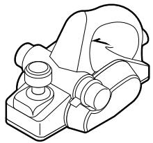
natural_image
Illustration of a Bosch electric shaver with lever and base mount (no text or symbols)Robert Bosch GmbH
Power Tools Division
70745 Leinfelden-Echterdingen
www.bosch-pt.com
1 609 929 N10 (2008.01) O / 107
PHO 20-82

BOSCH
de Originalbetriebsanleitung
en Original instructions
fr Notice originale
es Manual original
pt Manual original
it Istruzioni originali
nl Oorspronkelijke gebruiksaanwijzing
da Original brugsanvisning
sv Bruksanvisning i original
no Original driftsinstruks
fi Alkuperäiset ohjeet
1 609 929 N10 | (14.1.08)
Bosch Power Tools


Bosch Power Tools
1 609 929 N10 | (14.1.08)


6 | Deutsch
Dr. Egbert Schneider Senior Vice President Engineering
Dr. Eckerhard Strötgen Head of Product Certification

i.v. Mogen
29.11.2007, Robert Bosch GmbH, Power Tools Division D-70745 Leinfelden-Echterdingen
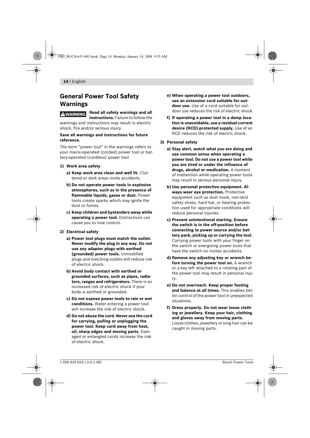
General Power Tool Safety Warnings
WARNING Read all safety warnings and all instructions. Failure to follow the
warnings and instructions may result in electric shock, fire and/or serious injury.
Save all warnings and instructions for future reference.
The term “power tool” in the warnings refers to your mains-operated (corded) power tool or battery-operated (cordless) power tool.
1) Work area safety
a) Keep work area clean and well lit. Cluttered or dark areas invite accidents.
b) Do not operate power tools in explosive atmospheres, such as in the presence of flammable liquids, gases or dust. Power tools create sparks which may ignite the dust or fumes.
c) Keep children and bystanders away while operating a power tool. Distractions can cause you to lose control.
2) Electrical safety
a) Power tool plugs must match the outlet. Never modify the plug in any way. Do not use any adapter plugs with earthed (grounded) power tools. Unmodified plugs and matching outlets will reduce risk of electric shock.
b) Avoid body contact with earthed or grounded surfaces, such as pipes, radiators, ranges and refrigerators. There is an increased risk of electric shock if your body is earthed or grounded.
c) Do not expose power tools to rain or wet conditions. Water entering a power tool will increase the risk of electric shock.
d) Do not abuse the cord. Never use the cord for carrying, pulling or unplugging the power tool. Keep cord away from heat, oil, sharp edges and moving parts. Damaged or entangled cords increase the risk of electric shock.
e) When operating a power tool outdoors, use an extension cord suitable for outdoor use. Use of a cord suitable for outdoor use reduces the risk of electric shock.
f) If operating a power tool in a damp location is unavoidable, use a residual current device (RCD) protected supply. Use of an RCD reduces the risk of electric shock.
3) Personal safety
a) Stay alert, watch what you are doing and use common sense when operating a power tool. Do not use a power tool while you are tired or under the influence of drugs, alcohol or medication. A moment of inattention while operating power tools may result in serious personal injury.
b) Use personal protective equipment. Always wear eye protection. Protective equipment such as dust mask, non-skid safety shoes, hard hat, or hearing protection used for appropriate conditions will reduce personal injuries.
c) Prevent unintentional starting. Ensure the switch is in the off-position before connecting to power source and/or battery pack, picking up or carrying the tool. Carrying power tools with your finger on the switch or energising power tools that have the switch on invites accidents.
d) Remove any adjusting key or wrench before turning the power tool on. A wrench or a key left attached to a rotating part of the power tool may result in personal injury.
e) Do not overreach. Keep proper footing and balance at all times. This enables better control of the power tool in unexpected situations.
f) Dress properly. Do not wear loose clothing or jewellery. Keep your hair, clothing and gloves away from moving parts.
Loose clothes, jewellery or long hair can be caught in moving parts.


g) If devices are provided for the connection of dust extraction and collection facilities, ensure these are connected and properly used. Use of dust collection can reduce dust-related hazards.
4) Power tool use and care
a) Do not force the power tool. Use the correct power tool for your application. The correct power tool will do the job better and safer at the rate for which it was designed.
b) Do not use the power tool if the switch does not turn it on and off. Any power tool that cannot be controlled with the switch is dangerous and must be repaired.
c) Disconnect the plug from the power source and/or the battery pack from the power tool before making any adjustments, changing accessories, or storing power tools. Such preventive safety measures reduce the risk of starting the power tool accidentally.
d) Store idle power tools out of the reach of children and do not allow persons unfamiliar with the power tool or these instructions to operate the power tool. Power tools are dangerous in the hands of untrained users.
e) Maintain power tools. Check for misalignment or binding of moving parts, breakage of parts and any other condition that may affect the power tool's operation. If damaged, have the power tool repaired before use. Many accidents are caused by poorly maintained power tools.
f) Keep cutting tools sharp and clean. Properly maintained cutting tools with sharp cutting edges are less likely to bind and are easier to control.
g) Use the power tool, accessories and tool bits etc. in accordance with these instructions, taking into account the working conditions and the work to be performed. Use of the power tool for operations different from those intended could result in a hazardous situation.
5) Service
a) Have your power tool serviced by a qualified repair person using only identical replacement parts. This will ensure that the safety of the power tool is maintained.
Machine-specific Safety Warnings
▶ Wait for the cutter to stop before setting the tool down. An exposed cutter may engage the surface leading to possible loss of control and serious injury.
▶ Do not reach into the saw dust ejector with your hands. They could be injured by rotating parts.
▶ Apply the machine to the workpiece only when switched on. Otherwise there is danger of kickback when the cutting tool jams in the workpiece.
When working, always hold the planer in such a manner that the planer base plate faces flat on the workpiece. Otherwise the planer can become wedged and lead to injuries.
▶ Never plane over metal objects, nails or screws. The planer blade and the blade shaft can become damaged and lead to increased vibrations.
- Secure the workpiece. A workpiece clamped with clamping devices or in a vice is held more secure than by hand.
▶ Never use the machine with a damaged cable. Do not touch the damaged cable and pull the mains plug when the cable is damaged while working. Damaged cables increase the risk of an electric shock.
Functional Description

Read all safety warnings and all instructions. Failure to follow the warnings and instructions may result in electric shock, fire and/or serious injury.
16 | English
Intended Use
The machine is intended for planing of firmly supported wooden materials, such as beams and boards. It is also suitable for beveling edges and rebating.
Product Features
The numbering of the product features refers to the illustration of the machine on the graphics page.
1 Chip ejector (alternatively right/left)
2 Depth adjustment knob
3 Planing depth scale
4 Chip ejection selector lever
5 On/Off switch
6 Safety switch for On/Off switching
7 Belt cover
8 Screws for belt cover
9 V-grooves
10 Planer base plate
11 Blade drum
12 Clamping element for blade
13 Fastening screw for planer blade
14 Carbide blade (TC)
15 Allen key*
16 Extraction hose ( 35 mm) ^*
17 Chip/dust bag*
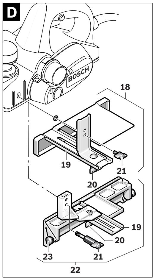
18 Parallel guide*
19 Scale for rebating width
20 Locking nut for adjustment of rebating width
21 Fastening bolt for parallel and beveling guide
22 Angle stop*
23 Locking nut for angle adjustment
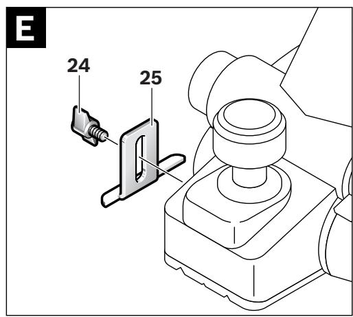
24 Fastening bolt for rebating depth stop
25 Rebating depth stop*
26 Park rest
27 Drive belt
28 Large pulley
29 Small pulley
*The accessories illustrated or described are not included as standard delivery.
**Commercially available (not included in the delivery scope)
Technical Data
| Planer | PHO 20-82 | |
| Article number | 0 603 365 1.. | |
| Rated power input | W | 680 |
| Output power | W | 320 |
| No-load speed | rpm | 19500 |
| Planing depth | mm | 0 – 2 |
| Rebating depth | mm | 0 – 8 |
| Planing width, max. | mm | 82 |
| Weight according to EPTA-Procedure 01/2003 | kg | 2.2 |
| Protection class | ☐/II | |
The values given are valid for nominal voltages [U] of 230/240 V. For lower voltage and models for specific countries, these values can vary.
Please observe the article number on the type plate of your machine. The trade names of the individual machines may vary.
Declaration of Conformity CE
We declare under our sole responsibility that the product described under “Technical Data” is in conformity with the following standards or standardization documents: EN 60745 according to the provisions of the directives 2004/108/EC, 98/37/EC (until Dec. 28, 2009), 2006/42/EC (from Dec. 29, 2009 on).
Technical file at:
Robert Bosch GmbH, PT/ESC,
D-70745 Leinfelden-Echterdingen
Dr. Egbert Schneider Dr. Eckerhard Strötgen
Senior Vice President Head of Product
Engineering Certification
ppa. Macau i.v. Nuoyen
29.11.2007, Robert Bosch GmbH, Power Tools Division D-70745 Leinfelden-Echterdingen


Noise/Vibration Information
Measured values determined according to EN 60745.
Typically the A-weighted noise levels of the product are: Sound pressure level 90 dB(A); Sound power level 101 dB(A). Uncertainty K=3 dB.
Wear hearing protection!
Vibration total values (triax vector sum) determined according to EN 60745:
Vibration emission value a_h<2.5 m/s^2 , Uncertainty K=1.5 m/s^2 .
The vibration emission level given in this information sheet has been measured in accordance with a standardised test given in EN 60745 and may be used to compare one tool with another. It may be used for a preliminary assessment of exposure.
The declared vibration emission level represents the main applications of the tool. However if the tool is used for different applications, with different accessories or poorly maintained, the vibration emission may differ. This may significantly increase the exposure level over the total working period.
An estimation of the level of exposure to vibration should also take into account the times when the tool is switched off or when it is running but not actually doing the job. This may significantly reduce the exposure level over the total working period.
Identify additional safety measures to protect the operator from the effects of vibration such as: maintain the tool and the accessories, keep the hands warm, organisation of work patterns.
Assembly
▶ Before any work on the machine itself, pull the mains plug.
Changing the Tool
▶ Be cautious when replacing the planer blades. Do not grasp the planer blades by the cutting edges. Possible danger of injury due to the sharp cutting edges of the planer blades.
Use only original Bosch carbide blades (TC).
The carbide blade (TC) has 2 cutting edges and can be reversed. When both cutting edges are dull, the planer blade 14 must be replaced. The carbide blade (TC) may not be resharpened.
Disassembling the Planer Blade(s) (see figure A)
To reverse or replace the planer blade 14, rotate the blade drum 11 until it is parallel to the planer base plate 10.
① Loosen the two fastening screws 13 with the Allen key 15 by approx. 1–2 turns.
② If necessary, loosen the clamping element 12 by giving it a light blow with a suitable tool (e.g. a wooden wedge).
③ Push the planer blade 14 sidewards out of the blade drum 11 with a piece of wood.
Assembling the Planer Blade(s) (see figure B)
The guide groove of the planer blade always ensures continuous height adjustment when replacing or reversing it.
If required, clean the blade seat in the clamping element 12 and the planer blade 14.
When assembling the planer blade, ensure that it is seated properly in the blade holder of the clamping element 12 and aligned flush at the side edge of the rear planer base plate 10. Afterwards tighten the 2 fastening screws 13 again with the Allen key 15.
Note: Before restarting, check if the fastening screws 13 are tightened well. Rotate the blade drum 11 by hand and ensure that the planer blade does not graze.
Dust/Chip Extraction
Dusts from materials such as lead-containing coatings, some wood types, minerals and metal can be harmful to one's health. Touching or breathing-in the dusts can cause allergic reactions and/or lead to respiratory infections of the user or bystanders.
18 | English
Certain dusts, such as oak or beech dust, are considered as carcinogenic, especially in connection with wood-treatment additives (chromate, wood preservative). Materials containing asbestos may only be worked by specialists.
- Use dust extraction whenever possible.
- Provide for good ventilation of the working place.
- It is recommended to wear a P2 filter-class respirator.
Observe the relevant regulations in your country for the materials to be worked.
Clean the chip ejector 1 regularly. Use a suitable tool (e.g., a piece of wood, compressed air, etc.) to clean a clogged chip ejector.
▶ Do not reach into the saw dust ejector with your hands. They could be injured by rotating parts.
To ensure optimum extraction of dust/chips, always work with external dust extraction or a chip/dust bag.
External Dust Extraction (see figure C)
An extraction hose ( 35 mm) 16 (accessory), can be attached on either side of the chip ejector.
Connect the vacuum hose 16 to a vacuum cleaner (accessory). An overview for connecting to various vacuum cleaners can be found at the end of this manual.
The vacuum cleaner must be suitable for the material being worked.
When vacuuming dry dust that is especially detrimental to health or carcinogenic, use a special vacuum cleaner.
Integrated Dust Extraction (see figure C)
A chip/dust bag (accessory) 17 can be used for smaller jobs. Insert the sleeve of the chip/dust bag firmly into the chip ejector 1. Empty the chip/dust bag 17 at regularly intervals to maintain optimum dust collection.
Choice of Chip Ejector Side
With the selector lever 4, the chip ejector 1 can be switched to right or left. Always press the selector lever 4 until it engages in the end position. The selected ejection direction is indicated by an arrow symbol on the selector lever 4.
Operation
Operating Modes
Adjusting the Planing Depth
With the adjustment knob 2, the planing depth can be adjusted variably from 0–2.0 mm using the planing depth scale 3 (scale graduation = 0.1 mm).
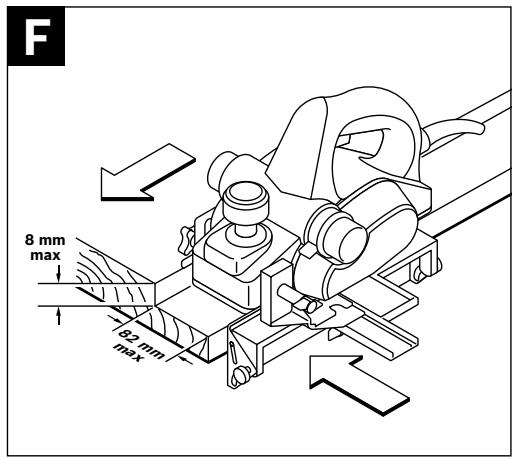
Park Rest (see figure G)
The park rest 26 allows the machine to be set down directly after operation, without danger of damaging the working surface or the planer blade. While planing, the park rest 26 is tilted upwards thus enabling full contact of the rear part of the planer base plate 10.
Note: The park rest 26 may not be removed.
Starting Operation
▶ Observe correct mains voltage! The voltage of the power source must agree with the voltage specified on the nameplate of the machine. Power tools marked with 230 V can also be operated with 220 V.
Switching On and Off
To start the machine, first push the lock-off button for the On/Off switch 6 and then press the On/Off switch 5 and keep it pressed.
To switch off the machine, release the On/Off switch 5.
Note: For safety reasons, the On/Off switch 5 cannot be locked; it must remain pressed during the entire operation.
Working Advice
Planing (see figure G)
Set the required planing depth and place the front part of the planer base plate 10 against the workpiece.
▶ Apply the machine to the workpiece only when switched on. Otherwise there is danger of kickback when the cutting tool jams in the workpiece.
Switch the machine on and guide the machine with even feed over the surface to be planed.
To achieve high-grade surfaces, work only with low feed and apply pressure on the centre of the planer base plate.
When machining hard materials (e.g. hardwood) as well as when utilising the maximum planer width, set only low planing depths and reduce planer feed, as required.
Excessive feed reduces the surface quality and can lead to rapid clogging of the chip ejector.
Only sharp blades achieve good cutting capacity and give the machine longer life.
The integrated park rest 26 also allows for continued planing at any given location on the workpiece after an interruption:
- With the park rest folded down, place the machine on the location of the workpiece where the planing is to be continued.
- Switch on the machine.
- Apply the supporting pressure onto the front part of the planer base plate and slowly push the machine forward (①). This tilts the park rest upward (②) so that the rear part of the planer base plate faces on the workpiece again.
- Guide the machine over the surface to be planed (③) with even feed.
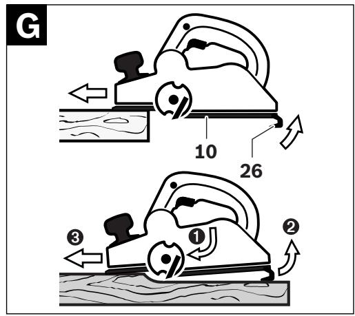
Beveling Edges (see figure H)
The V-grooves in the front planer base plate allow quick and easy beveling of workpiece edges. Depending on required bevel width, use the corresponding V-groove. For this, place the planer with the V-groove onto the edge of the workpiece and guide it along the edge.
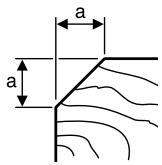
Groove to be
used
none
small
medium
large
Dimension a
(mm)
0-2.5
1.0 - 4,5
2.0-5.0
2.5-6.0
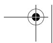
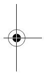
Planing with Parallel/Beveling Guide (see figures D-F)
Mount the parallel guide 18 or beveling guide 22 to the machine using the corresponding fastening bolt 21. Depending on the application, mount the rebating depth stop 25 with fastening bolt 24 to the machine.
Loosen the locking nut 20 and adjust the requested rebating width on the scale 19. Tighten the locking nut 20 again.
Adjust the requested rebating depth accordingly with the rebating depth stop 25.
Carry out the planing procedure several times until the requested rebating depth is reached. Guide the planer applying sideward supporting pressure.
Beveling with the Beveling Guide
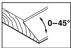
When beveling rebates and surfaces, adjust the required slope angle with the angle adjustment 23.
Maintenance and Service
Maintenance and Cleaning
▶ Before any work on the machine itself, pull the mains plug.
▶ For safe and proper working, always keep the machine and ventilation slots clean.
Ensure easy operation of the park rest 26 and clean it regularly.
If the machine should fail despite the care taken in manufacturing and testing procedures, repair should be carried out by an after-sales service centre for Bosch power tools.


20 | English
In all correspondence and spare parts order, please always include the 10-digit article number given on the type plate of the machine.
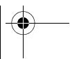
WARNING! Important instructions for connecting a new 3-pin plug to the 2-wire cable.
The wires in the cable are coloured according to the following code:
Do not connect the blue or brown wire to the earth terminal of the plug.
Important: If for any reason the moulded plug is removed from the cable of this power tool, it must be disposed of safely.
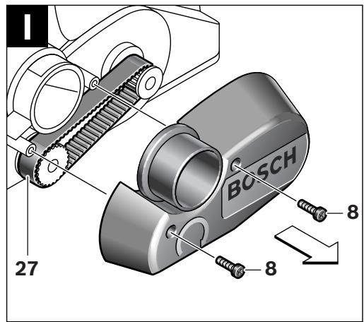
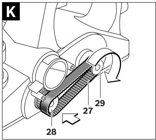
Replacing the Drive Belt (see figures I-K)
Unscrew the screws 8 and take off the belt cover 7. Remove the worn drive belt 27.
Before assembling a new drive belt 27, clean both pulleys 28 and 29.
Place the new drive belt 27 on the small pulley 29 first and then work the drive belt 27 onto the large pulley 28 by hand while rotating it.
Mount the belt cover 7 again and tighten the screws 8.
After-sales Service and Customer Assistance
Our after-sales service responds to your questions concerning maintenance and repair of your product as well as spare parts. Exploded views and information on spare parts can also be found under:
www.bosch-pt.com
Our customer consultants answer your questions concerning best buy, application and adjustment of products and accessories.
Great Britain
Robert Bosch Ltd. (B.S.C.)
P.O. Box 98
Broadwater Park
North Orbital Road
Denham
Uxbridge
UB 9 5HJ
Tel. Service: +44 (0844) 736 0109
Fax: +44 (0844) 736 0146
Australia, New Zealand and Pacific Islands
Robert Bosch Australia Pty. Ltd.
Power Tools
Locked Bag 66
Clayton South VIC 3169
Customer Contact Center
Inside Australia:
Phone: +61 (01300) 307 044
Fax: +61 (01300) 307 045
Inside New Zealand:
Phone: +64 (0800) 543 353
Fax: +64 (0800) 428 570
Outside AU and NZ:
Phone: +61 (03) 9541 5555
www.bosch.com.au

English | 21
Disposal
The machine, accessories and packaging should be sorted for environmental-friendly recycling.
Only for EC countries:

Do not dispose of power tools into household waste! According to the European Guideline 2002/96/EC for Waste Electrical and Electronic Equipment and its implementation into national right,
power tools that are no longer usable must be collected separately and disposed of in an environmentally correct manner.
Subject to change without notice.


natural_image
Pure geometric lines and crosshair symbols without any text or labels


natural_image
Pure geometric lines and crosshair symbols without any text or labels
22 | Français
Dr. Egbert Schneider Dr. Eckerhard Strötgen Senior Vice President Head of Product Engineering Certification
ppu. Mawita i.v. Nuoyen
29.11.2007, Robert Bosch GmbH, Power Tools Division D-70745 Leinfelden-Echterdingen
Robert Bosch (France) S.A.S.
Senior Vice President Head of Product
Engineering Certification
ppa. Macau i.v. Nuoyen
29.11.2007, Robert Bosch GmbH, Power Tools Division D-70745 Leinfelden-Echterdingen
Dr. Egbert Schneider Senior Vice President Engineering
Dr. Eckerhard Strötgen Head of Product Certification

29.11.2007, Robert Bosch GmbH, Power Tools Division D-70745 Leinfelden-Echterdingen
Senior Vice President
Engineering
Dr. Eckerhard Strötgen
Head of Product
Certification
ppa. Macaca i.v. Nuoyen
29.11.2007, Robert Bosch GmbH, Power Tools Division D-70745 Leinfelden-Echterdingen
Senior Vice President
Head of Product
Engineering
Certification

i.v. Nguyen
29.11.2007, Robert Bosch GmbH, Power Tools Division D-70745 Leinfelden-Echterdingen
Senior Vice President
Engineering
Dr. Eckerhard Strötgen
Head of Product
Certification

29.11.2007, Robert Bosch GmbH, Power Tools Division D-70745 Leinfelden-Echterdingen
Støj-/vibrationsinformation
Bosch Service Center
Telegrafvej 3
2750 Ballerup
Tel. Service Center: +45 (04489) 8855
Fax: +45 (04489) 87 55
E-Mail: vaerktoej@dk.bosch.com
Bortskaffelse
Dr. Egbert Schneider Dr. Eckerhard Strötgen Senior Vice President Head of Product Engineering Certification
ppa. Macau i.v. Nuoyen
29.11.2007, Robert Bosch GmbH, Power Tools Division D-70745 Leinfelden-Echterdingen


72 | Svenska
Buller-/vibrationsdata
Senior Vice President
Engineering
Dr. Eckerhard Strötgen
Head of Product
Certification

i.v. Mogen
29.11.2007, Robert Bosch GmbH, Power Tools Division D-70745 Leinfelden-Echterdingen
Dr. Egbert Schneider Senior Vice President Engineering
Dr. Eckerhard Strötgen Head of Product Certification

29.11.2007, Robert Bosch GmbH, Power Tools Division D-70745 Leinfelden-Echterdingen
Melu-/tärinätiedot
Senior Vice President
Engineering
Dr. Eckerhard Strötgen
Head of Product
Certification
ppa. Mauca
i.v. Mogen
29.11.2007, Robert Bosch GmbH, Power Tools Division D-70745 Leinfelden-Echterdingen
94 | Ελληνικά
Senior Vice President
Engineering
Dr. Eckerhard Strötgen
Head of Product
Certification

29.11.2007, Robert Bosch GmbH, Power Tools Division D-70745 Leinfelden-Echterdingen
Gürültü/Titreşim bilgisi
Bosch San. ve Tic. A.S.
Ahi Evran Cad. No:1 Kat:22
Polaris Plaza
80670 Maslak/Istanbul
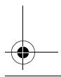
natural_image
Simple line drawing of a tool or plunger with a circular highlight (no text or symbols)1x:
2 608 635 376
2x:
2 608 635 350
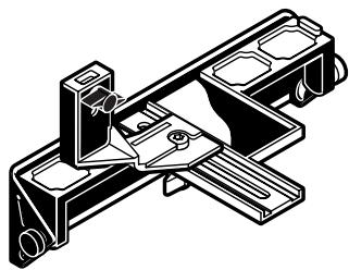
natural_image
Technical line drawing of a mechanical assembly with no visible text or symbols2 607 001 078
(45°)
2 605 411 035
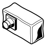
natural_image
Technical line drawing of a mechanical component with no visible text or symbols


∅ 35 mm
3 m 2 607 002 149
5 m 2 607 002 150
PAS 11-21
PAS 12-27
PAS 12-27 F


- PHO 20-82
- BOSCH
- | Deutsch
- General Power Tool Safety Warnings
- WARNING Read all safety warnings and all instructions. Failure to follow the
- Save all warnings and instructions for future reference.
- 1) Work area safety
- 2) Electrical safety
- 3) Personal safety
- 4) Power tool use and care
- 5) Service
- Machine-specific Safety Warnings
- Functional Description
- | English
- Intended Use
- Product Features
- Declaration of Conformity CE
- Noise/Vibration Information
- Wear hearing protection!
- Assembly
- Changing the Tool
- Disassembling the Planer Blade(s) (see figure A)
- Assembling the Planer Blade(s) (see figure B)
- Dust/Chip Extraction
- | English
- External Dust Extraction (see figure C)
- Integrated Dust Extraction (see figure C)
- Choice of Chip Ejector Side
- Operation
- Operating Modes
- Adjusting the Planing Depth
- Park Rest (see figure G)
- Starting Operation
- Switching On and Off
- Working Advice
- Planing (see figure G)
- Beveling Edges (see figure H)
- Groove to be
- Dimension a
- Planing with Parallel/Beveling Guide (see figures D-F)
- Beveling with the Beveling Guide
- Maintenance and Service
- Maintenance and Cleaning
- | English
- WARNING! Important instructions for connecting a new 3-pin plug to the 2-wire cable.
- Replacing the Drive Belt (see figures I-K)
- After-sales Service and Customer Assistance
- www.bosch-pt.com
- Great Britain
- Australia, New Zealand and Pacific Islands
- Disposal
- Only for EC countries:
- | Français
- Støj-/vibrationsinformation
- Bortskaffelse
- | Svenska
- Buller-/vibrationsdata
- Melu-/tärinätiedot
- | Ελληνικά
- Gürültü/Titreşim bilgisi
Brand : BOSCH
Model : PHO 20-82
Category : Planer