
GHO 1682 Professional - Planer BOSCH - Free user manual and instructions
Find the device manual for free GHO 1682 Professional BOSCH in PDF.
| Product type | Electric planer |
| Brand | Bosch |
| Model | GHO 1682 Professional |
| Rated power input | 630 W (GHO 16-82) / 710 W (GHO 26-82 D) |
| No-load speed | 18,000 rpm |
| Max planing width | 82 mm |
| Depth of cut | 0 - 1.6 mm (GHO 16-82) / 0 - 2.6 mm (GHO 26-82 D) |
| Depth of rebate | 0 - 9 mm |
| Weight (according to EPTA) | 3.4 kg |
| Power supply | Mains, 230 V, 50/60 Hz |
| Protection class | II (double insulation) |
| Blade type | Carbide (HM/TC), reversible, 2 cutting edges |
| Chip ejection | Fixed (GHO 16-82) / Adjustable right/left (GHO 26-82 D) |
| Base | With V-groove for chamfering |
| Included accessories | Hex key, parallel stop, angle stop, depth stop, dust bag (depending on version) |
| Rest pad | Integrated for safe placement |
| Dust extraction system | Connection for vacuum cleaner (Ø 35 mm) or dust bag |
| Maintenance | Cleaning ventilation slots, carbon brush replacement by service center |
| Sound level | Sound pressure 84 dB(A), sound power 95 dB(A) |
| Vibrations | a_h = 8 m/s², uncertainty K = 1.5 m/s² |
Frequently Asked Questions - GHO 1682 Professional BOSCH
User questions about GHO 1682 Professional BOSCH
0 question about this device. Answer the ones you know or ask your own.
Ask a new question about this device
Download the instructions for your Planer in PDF format for free! Find your manual GHO 1682 Professional - BOSCH and take your electronic device back in hand. On this page are published all the documents necessary for the use of your device. GHO 1682 Professional by BOSCH.
USER MANUAL GHO 1682 Professional BOSCH
natural_image
Illustration of two Bosch tool holders with handles and shafts (no text or symbols)GHO Professional
16-82|26-82D

BOSCH
da Original drugs are using
su Bruksquisning Loriginal
34 crosslinking longline
no Original driftsinst
fi Alkuperålset onjeet
The following section is a diagram illustrating the structure of a system. The diagram contains no text, only graphical elements (e.g., 'a', 'b') and labels (e.g., 'a', 'b') are part of a diagram without textual content. No valid OCR text can be extracted from the image.
April desseign les apples
دکترچه رامنماي اصلی
Deutsch......Seite 6
English ...... page 11
Français......Page 16
Español ...... Página 22
Português ...... Página 28
Italiano ...... Pagina 34
Nederlands.... Pagina 39
Dansk ...... Side 45
Svensk .... Sidan 49
Norsk.... Side 54
Suomi Sivu 59
Ελληνικά...... Σελίδα 63
Türkçe...... Sayfa 69
Polski ...... Strona 75
Čeština.... Stránka 81
Slovenčina ...... Stránka 86
Magyar ....Oldal 91
Русский...... Страница 96
Українська ...... Сторінка 103
Казак...... Бет 109
Română ...... Pagina 115
Български ...... Страница 120
Македонски.... Страница 126
Srpski Strana 132
Slovenščina ....Stran 137
Hrvatski....Stranica 142
Eesti......Lehekülg 147
Latviešu .... Lappuse 152
Lietuvių k. ......Puslapis 157
한국어....페이지 162
168 عربيالصفحة
174 آفارسی
CE
|
4
1 609 92A 4LF | (26.10.2018) Bosch Power Tools
Bosch Power Tools 1 609 92A 4LF | (26.10.2018)
Deutsch
Sicherheitshinweise
General Power Tool Safety Warnings
WARNING
Read all safety warnings, instructions, illustrations and specifica-
tions provided with this power tool. Failure to follow all instructions listed below may result in electric shock, fire and/or serious injury.
Save all warnings and instructions for future reference.
The term "power tool" in the warnings refers to your mains-operated (corded) power tool or battery-operated (cordless) power tool.
Work area safety
▶ Keep work area clean and well lit. Cluttered or dark areas invite accidents.
▶ Do not operate power tools in explosive atmospheres, such as in the presence of flammable liquids, gases or dust. Power tools create sparks which may ignite the dust or fumes.
▶ Keep children and bystanders away while operating a power tool. Distractions can cause you to lose control.
Electrical safety
▶ Power tool plugs must match the outlet. Never modify the plug in any way. Do not use any adapter plugs with earthed (grounded) power tools. Unmodified plugs and matching outlets will reduce risk of electric shock.
▶ Avoid body contact with earthed or grounded surfaces, such as pipes, radiators, ranges and refrigerators. There is an increased risk of electric shock if your body is earthed or grounded.
▶ Do not expose power tools to rain or wet conditions. Water entering a power tool will increase the risk of electric shock.
▶ Do not abuse the cord. Never use the cord for carrying, pulling or unplugging the power tool. Keep cord away from heat, oil, sharp edges or moving parts.
Damaged or entangled cords increase the risk of electric shock.
When operating a power tool outdoors, use an extension cord suitable for outdoor use. Use of a cord suitable for outdoor use reduces the risk of electric shock.
If operating a power tool in a damp location is unavoidable, use a residual current device (RCD) protected supply. Use of an RCD reduces the risk of electric shock.
Personal safety
▶ Stay alert, watch what you are doing and use common sense when operating a power tool. Do not use a
12 | English
power tool while you are tired or under the influence of drugs, alcohol or medication. A moment of inattention while operating power tools may result in serious personal injury.
▶ Use personal protective equipment. Always wear eye protection. Protective equipment such as a dust mask, non-skid safety shoes, hard hat or hearing protection used for appropriate conditions will reduce personal injuries.
▶ Prevent unintentional starting. Ensure the switch is in the off-position before connecting to power source and/or battery pack, picking up or carrying the tool. Carrying power tools with your finger on the switch or energising power tools that have the switch on invites accidents.
Remove any adjusting key or wrench before turning the power tool on. A wrench or a key left attached to a rotating part of the power tool may result in personal injury.
▶ Do not overreach. Keep proper footing and balance at all times. This enables better control of the power tool in unexpected situations.
▶ Dress properly. Do not wear loose clothing or jewellery. Keep your hair and clothing away from moving parts. Loose clothes, jewellery or long hair can be caught in moving parts.
▶ If devices are provided for the connection of dust extraction and collection facilities, ensure these are connected and properly used. Use of dust collection can reduce dust-related hazards.
Do not let familiarity gained from frequent use of tools allow you to become complacent and ignore tool safety principles. A careless action can cause severe injury within a fraction of a second.
Power tool use and care
▶ Do not force the power tool. Use the correct power tool for your application. The correct power tool will do the job better and safer at the rate for which it was designed.
▶ Do not use the power tool if the switch does not turn it on and off. Any power tool that cannot be controlled with the switch is dangerous and must be repaired.
▶ Disconnect the plug from the power source and/or remove the battery pack, if detachable, from the power tool before making any adjustments, changing accessories, or storing power tools. Such preventive safety measures reduce the risk of starting the power tool accidentally.
▶ Store idle power tools out of the reach of children and do not allow persons unfamiliar with the power tool or these instructions to operate the power tool. Power tools are dangerous in the hands of untrained users.
- Maintain power tools and accessories. Check for misalignment or binding of moving parts, breakage of parts and any other condition that may affect the power tool's operation. If damaged, have the power
tool repaired before use. Many accidents are caused by poorly maintained power tools.
▶ Keep cutting tools sharp and clean. Properly maintained cutting tools with sharp cutting edges are less likely to bind and are easier to control.
▶ Use the power tool, accessories and tool bits etc. in accordance with these instructions, taking into account the working conditions and the work to be performed. Use of the power tool for operations different from those intended could result in a hazardous situation.
▶ Keep handles and grasping surfaces dry, clean and free from oil and grease. Slippery handles and grasping surfaces do not allow for safe handling and control of the tool in unexpected situations.
Service
▶ Have your power tool serviced by a qualified repair person using only identical replacement parts. This will ensure that the safety of the power tool is maintained.
Safety instructions for planers
▶ Wait for the cutter to stop before setting the tool down. An exposed rotating cutter may engage the surface leading to possible loss of control and serious injury.
▶ Hold the power tool by insulated gripping surfaces, because the cutter may contact its own cord. Cutting a "live" wire may make exposed metal parts of the power tool "live" and could give the operator an electric shock.
▶ Use clamps or another practical way to secure and support the workpiece to a stable platform. Holding the workpiece by your hand or against the body leaves it unstable and may lead to loss of control.
▶ Only bring the power tool into contact with the workpiece when switched on. Otherwise there is danger of kickback if the cutting tool jams in the workpiece.
▶ Do not allow the chip ejector to come into contact with your hands. You may be injured by rotating parts.
▶ Never plane over metal objects, nails or screws. Cutters and cutter shafts could become damaged and cause increased vibration.
▶ Use suitable detectors to determine if utility lines are hidden in the work area or call the local utility company for assistance. Contact with electric lines can lead to fire and electric shock. Damaging a gas line can lead to explosion. Penetrating a water line causes property damage or may cause an electric shock.
▶ While working, always hold the planer in such a way that the planer base plate lies flat against the workpiece. Otherwise the planer could slip and cause injury.
Products sold in GB only:
Your product is fitted with an BS 1363/A approved electric plug with internal fuse (ASTA approved to BS 1362). If the plug is not suitable for your socket outlets, it should be cut off and an appropriate plug fitted in its place by an authorised customer service agent. The replacement plug should have the same fuse rating as the original plug.
The severed plug must be disposed of to avoid a possible shock hazard and should never be inserted into a mains socket elsewhere.
▶ Hold the power tool firmly with both hands and make sure you have a stable footing. The power tool can be more securely guided with both hands.
Product Description and Specifications

Read all the safety and general instructions. Failure to observe the safety and general instructions may result in electric shock, fire and/or serious injury.
Please observe the illustrations at the beginning of this operating manual.
Intended use
The power tool is intended for planing wood-based materials such as beams and boards while resting firmly on the workpiece. It is also suitable for chamfering edges and for rebating.
Product features
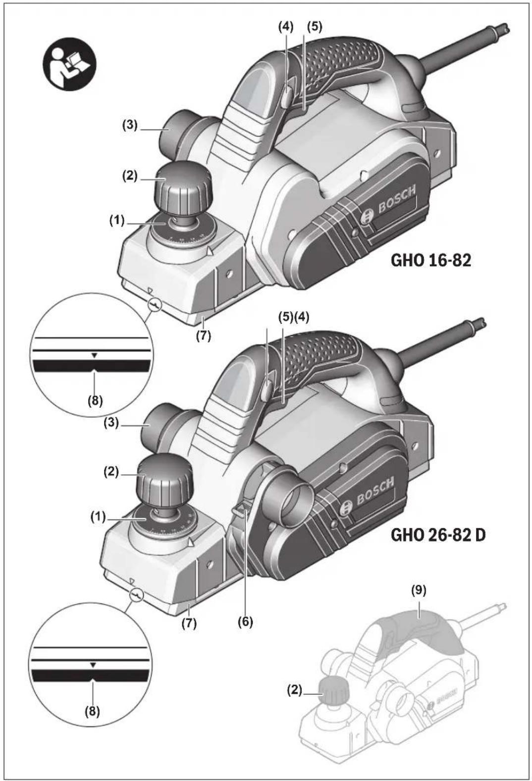
The numbering of the product features refers to the diagram of the power tool on the graphics page.
(1) Cutting depth scale
(2) Knob for setting the cutting depth (insulated gripping surface)
(3) Chip ejector (GHO 26-82 D: Either right or left)
(4) Lock-off button for on/off switch
(5) On/off switch
(6) Changeover lever for chip ejector direction (GHO 26-82 D)
(7) Planer base plate
(8) V-groove
(9) Handle (insulated gripping surface)
(10) Blade head
(11) Clamping element for planer blade
(12) Fastening screw for planer blade
(13) HM/TC planer blade
(14) Hex key
(15) Extraction hose (dia. 35 mm) ^A)
(16) Chip/dust bag ^A
(17) Parallel guide
(18) Scale for rebate width
(19) Locking nut for rebate width setting
(20) Fastening screw for parallel/angle guide
(21) Angle guide ^A)
(22) Locking nut for angle setting
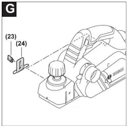
(23) Fastening screw for rebate depth guide
(24) Rebate depth guide ^A)
(25) Parking rest
A) Accessories shown or described are not included with the product as standard. You can find the complete selection of accessories in our accessories range.
Technical data
| Planer GHO 16-82 GHO 26-82 D | ||
| Article number | 3 601 EA4 0.. 3 601 EA4 3.. | |
| Rated power input W 630 710 | ||
| No-load speed rpm 18,000 18,000 | ||
| Cutting depth mm 0–1.6 0–2.6 | ||
| Rebate depth mm 0–9 0–9 | ||
| Max. planing width mm 82 82 | ||
| Weight according to EPTA-Procedure 01:2014 kg 3.4 3.4 | ||
| Protection class / II / II | ☐ | ☐ |
The specifications apply to a rated voltage [U] of 230 V. These specifications may vary at different voltages and in country-specific models.
Noise/vibration information
Noise emission values determined according to EN 62841-2-14.
Typically the A-weighted noise level of the power tool is: Sound pressure level 84 dB(A); sound power level 95 dB(A). Uncertainty K = 3 dB.
Wear hearing protection
Total vibration values a_h (triax vector sum) and uncertainty K determined according to EN 62841-2-14: a_h=8 m/s^2, K=1.5 m/s^2
The vibration level and noise emission value given in these instructions have been measured in accordance with a standardised measuring procedure and may be used to compare power tools. They may also be used for a preliminary estimation of vibration and noise emissions.
14 | English
The stated vibration level and noise emission value represent the main applications of the power tool. However, if the power tool is used for other applications, with different application tools or is poorly maintained, the vibration level and noise emission value may differ. This may significantly increase the vibration and noise emissions over the total working period.
To estimate vibration and noise emissions accurately, the times when the tool is switched off or when it is running but not actually being used should also be taken into account. This may significantly reduce vibration and noise emissions over the total working period.
Implement additional safety measures to protect the operator from the effects of vibration, such as servicing the power tool and application tools, keeping their hands warm, and organising workflows correctly.
Fitting
▶ Pull the plug out of the socket before carrying out any work on the power tool.
Changing the Tool
▶ Take care when changing the planer blade. Do not pick up the planer blade by the cutting edges. You may be injured by the sharp cutting edges.
Use only original Bosch HM/TC planer blades.
The hard metal (HM/TC) planer blade has two cutting edges and can be turned. If both cutting edges become blunt, the planer blade (13) needs to be changed. The HM/TC planer blade must not be resharpened.
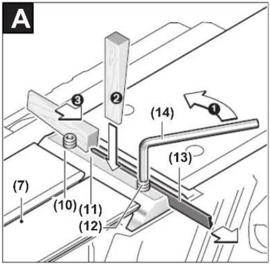
Removing the planer blade (see figure A)
To turn or replace the planer blade (13), turn the blade head (10) until it is parallel to the planer base plate (7).
① Loosen the two fastening screws (12) using the hex key (14) (approx. 1–2 turns).
② If necessary, loosen the clamping element (11) by lightly striking it with an appropriate implement, e.g. a wooden wedge.
③ Use a piece of wood to push the planer blade (13) to the side and out of the blade head (10).
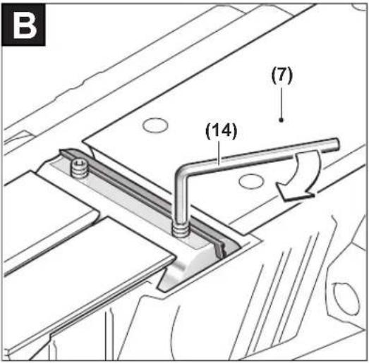
Fitting the planer blade (see figure B)
The guide groove on the planer blade ensures a constant, even height setting when changing or turning the blade. If necessary, clean the knife seat in the clamping element (11) and the planer blade (13).
When fitting the planer blade, ensure that it is correctly seated in the mounting guide of the clamping element (11). The planer blade must be fitted and aligned with the centre of the planer base plate (7). Then tighten the two fastening screws (12) with the hex key (14).
Note: Check that the fastening screws (12) are firmly tightened before starting operation. Turn the blade head (10) by hand and ensure that the planer blade is not brushing against anything.
Dust/Chip Extraction
The dust from materials such as lead paint, some types of wood, minerals and metal can be harmful to human health. Touching or breathing in this dust can trigger allergic reactions and/or cause respiratory illnesses in the user or in people in the near vicinity.
Certain dusts, such as oak or beech dust, are classified as carcinogenic, especially in conjunction with wood treatment additives (chromate, wood preservative). Materials containing asbestos may only be machined by specialists.
- Use a dust extraction system that is suitable for the material wherever possible.
- Provide good ventilation at the workplace.
- It is advisable to wear a P2 filter class breathing mask.
The regulations on the material being machined that apply in the country of use must be observed.
- Avoid dust accumulation at the workplace. Dust can easily ignite.
Clean the chip ejector (3) regularly. Clean a clogged chip ejector using a suitable tool, e.g. a piece of wood, compressed air, etc.
▶ Do not allow the chip ejector to come into contact with your hands. You may be injured by rotating parts.
Always use an external dust extraction device or chip/dust bag to guarantee optimum suction.
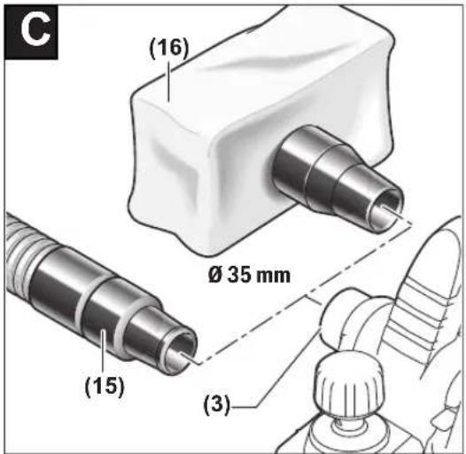
External dust extraction (see figure C)
Connect an extraction hose (15) (accessory) to the chip ejector (3).
Connect the extraction hose (15) to a dust extractor (accessory). You will find an overview of how to connect to various dust extractors at the end of these operating instructions. The dust extractor must be suitable for the material being worked.
When extracting dry dust that is especially detrimental to health or carcinogenic, use a special dust extractor.
Self-generated dust extraction (see figure C)
A dust/chip bag (accessory) (16) can be used for smaller jobs. Insert the dust bag nozzle of the chip/dust bag firmly into the chip ejector (3). Empty the chip/dust bag (16) at regular intervals to maintain optimum dust collection.
Adjustable chip ejector (GHO 26-82 D)
Using the changeover lever (6), the chip ejector can be (3) adjusted to the right or left. Always push the changeover lever (6) towards the end position until it clicks into place. The selected chip ejector direction is indicated by an arrow symbol on the changeover lever (6).
Operation
Operating modes
Setting the cutting depth
Using the knob (2), the cutting depth can be continuously adjusted between 0–1.6 mm (GHO 16-82) or 0–2.6 mm
(GHO 26-82 D) with the aid of the cutting depth scale (1) (scale division = 0.1 mm).
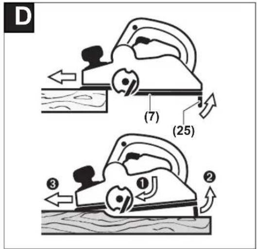
Parking rest (see figure D)
The parking rest (25) makes it possible to put down the power tool directly after working, without any danger of damaging the workpiece or planer blade. During the work process, the parking rest (25) is highly pivoted and the rear section of the planer base plate (7) is released.
Note: The parking rest (25) must not be removed.
Start-up
Pay attention to the mains voltage. The voltage of the power source must match the voltage specified on the rating plate of the power tool. Power tools marked with 230 V can also be operated with 220 V.
▶ Products that are only sold in AUS and NZ: Use a residual current device (RCD) with a nominal residual current of 30 mA or less.
Switching on/off
▶ Make sure that you are able to press the On/Off switch without releasing the handle.
To start the power tool, first press the lock-off button (4), then press and hold the on/off switch (5).
To switch off the power tool, release the on/off switch (5).
Note: For safety reasons, the on/off switch (5) cannot be locked; it must remain pressed during the entire operation.
Practical advice
▶ Pull the plug out of the socket before carrying out any work on the power tool.
Planing Procedure (see figure D)
Set the required cutting depth and position the power tool with the front section of the planer base plate (7) on the workpiece.
▶ Only bring the power tool into contact with the workpiece when switched on. Otherwise there is danger of kickback if the cutting tool jams in the workpiece.
Switch on the power tool and guide it over the surface of the workpiece, applying uniform feed.
To achieve high-quality surfaces, apply only a low feed rate and exert pressure on the middle of the planer base plate.
For the processing of hard materials, such as hardwood, and also when utilising the maximum planing width, set only a low cutting depth and reduce the planer feed as appropriate.
Excessive feed reduces the quality of the surface finish and can lead to the chip ejector quickly becoming blocked.
Only sharp planer blades achieve good cutting performance and make the power tool last longer.
The integrated parking rest (25) also enables a continuation of the planing procedure following interruption at any point on the workpiece:
- Place the power tool – with parking rest folded down – onto the area of the workpiece that you will continue to work on.
- Switch the power tool on.
- Shift the contact pressure onto the front of the planer base plate and slowly slide the power tool forward (1). In doing so, the parking rest will swivel upwards and out of the way (2), meaning that the rear section of the planer base plate is in contact with the workpiece again.
- Guide the power tool over the surface of the workpiece, applying uniform feed (③).
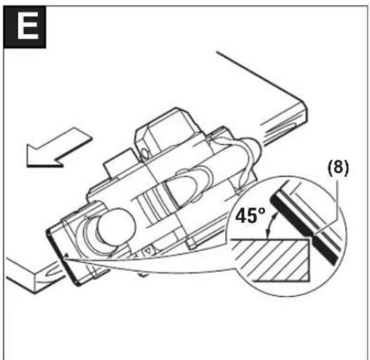
Chamfering edges (see figure E)
The V-groove (8) in the front of the planer base plate enables quick and easy chamfering of workpiece edges. Position the planer with the V-groove onto the edge of the workpiece and guide it along.
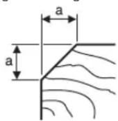
Groove used Dimension a (mm)
None 0–4
Medium 4–9
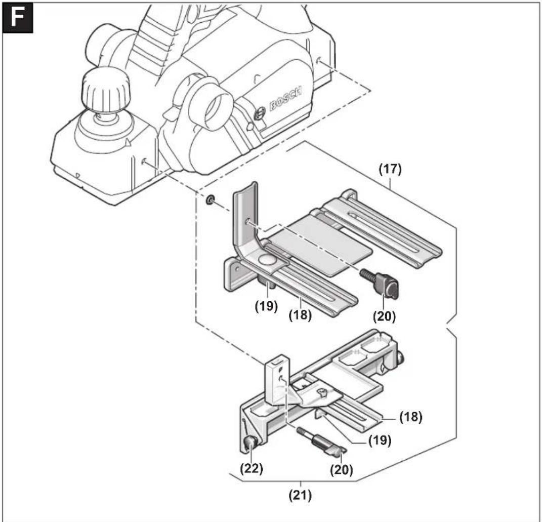
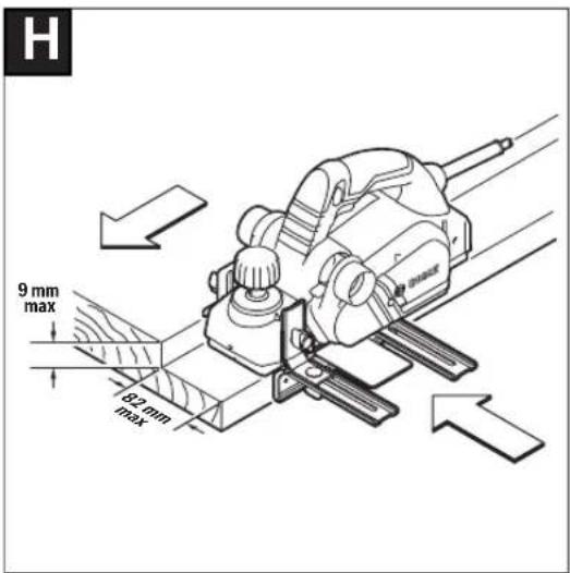
Planing with the parallel/angle guide (see figures F-H)
Mount the parallel guide (17) or the angle guide (21) on the power tool (either at the front or back) with the fastening screw (20). Depending on the application, mount the rebate depth guide (24) on the power tool (either at the front or back) with the fastening screw (23).
Loosen the locking nut (19) and set the desired rebate width on the scale (18). Retighten the locking nut (19).
Set the desired rebate depth accordingly using the rebate depth guide (24).
Carry out the planing procedure several times until the desired rebate depth has been achieved. Guide the planer with sideways contact pressure.
Chamfering with angle guide
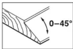
Use the angle setting (22) to set the necessary helix angle when chamfering grooves and surfaces.
Maintenance and Servicing
Maintenance and cleaning
▶ Pull the plug out of the socket before carrying out any work on the power tool.
▶ To ensure safe and efficient operation, always keep the power tool and the ventilation slots clean.
Keep the parking rest (25) clear and clean it regularly.
When the carbon brushes are worn out, the power tool switches itself off. The power tool must be sent to the after-sales service for maintenance; see the "After-sales service and advice on using products" section for addresses.
16 | Français
In order to avoid safety hazards, if the power supply cord needs to be replaced, this must be done by Bosch or by a customer service centre that is authorised to repair Bosch power tools.
After-sales service and advice on using products
Our after-sales service responds to your questions concerning maintenance and repair of your product as well as spare parts. You can find explosion drawings and information on spare parts at: www.bosch-pt.com
The Bosch product use advice team will be happy to help you with any questions about our products and their accessories.
In all correspondence and spare parts orders, please always include the 10-digit article number given on the nameplate of the product.
Great Britain
Robert Bosch Ltd. (B.S.C.)
P.O. Box 98
Broadwater Park
North Orbital Road
Denham Uxbridge
UB 9 5HJ
At www.bosch-pt.co.uk you can order spare parts or arrange the collection of a product in need of servicing or repair.
Tel. Service: (0344) 7360109
E-Mail: boschservicecentre@bosch.com
Ireland
Origo Ltd.
Unit 23 Magna Drive
Magna Business Park
City West
Dublin 24
Tel. Service: (01) 4666700
Fax: (01) 4666888
Australia, New Zealand and Pacific Islands
Robert Bosch Australia Pty. Ltd.
Power Tools
Locked Bag 66
Clayton South VIC 3169
Customer Contact Center
Inside Australia:
Phone: (01300) 307044
Fax: (01300) 307045
Inside New Zealand:
Phone: (0800) 543353
Fax: (0800) 428570
Outside AU and NZ:
Phone: +61 3 95415555
www.bosch-pt.com.au
www.bosch-pt.co.nz
Republic of South Africa
Customer service
Hotline: (011) 6519600
Gauteng - BSC Service Centre
35 Roper Street, New Centre
Johannesburg
Tel.: (011) 4939375
Fax: (011) 4930126
E-mail: bsctools@icon.co.za
KZN - BSC Service Centre
Unit E, Almar Centre
143 Crompton Street
Pinetown
Tel.: (031) 7012120
Fax: (031) 7012446
E-mail: bsc.dur@za.bosch.com
Western Cape – BSC Service Centre
Democracy Way, Prosperity Park
Milnerton
Tel.: (021) 5512577
Fax: (021) 5513223
E-mail: bsc@zsd.co.za
Bosch Headquarters
Midrand, Gauteng
Tel.: (011) 6519600
Fax: (011) 6519880
E-mail: rbsa-hq.pts@za.bosch.com
Disposal
The power tool, accessories and packaging should be recycled in an environmentally friendly manner.

Do not dispose of power tools along with household waste.
Only for EU countries:
According to the European Directive 2012/19/EU on Waste Electrical and Electronic Equipment and its implementation into national law, power tools that are no longer usable must be collected separately and disposed of in an environmentally friendly manner.
Français
Robert Bosch (France) S.A.S.
Calle Robert Bosch No. 405
Bosch Service Center
Telegrafvej 3
2750 Ballerup
På www.bosch-pt.dk kan der online bestilles reservedele eller oprettes en reparations ordre.
Tlf. Service Center: 44898855
Fax: 44898755
E-Mail: vaerktoej@dk.bosch.com
Bortskaffelse
Bosch Service Center
Telegrafvej 3
2750 Ballerup
Danmark
Tel.: (08) 7501820 (inom Sverige)
Fax: (011) 187691
Avfallshantering
Robert Bosch Sp. z o.o.
Bosch Service Center PT
K Vápence 1621/16
692 01 Mikulov
$$ a _ {n} = 8 \mathrm{M} / c ^ {2}, K = 1, 5 \mathrm{M} / c ^ {2}, $$
Service scule electrice
Strada Horia Măcelariu Nr. 30-34, sector 1
013937 Bucureşti
Service scule electrice
Strada Horia Măcelariu Nr. 30-34, sector 1
013937 Bucureşti, România
www.bosch-pt.com/bg/bg/
Бракуване


- GHO Professional
- BOSCH
- Deutsch
- Sicherheitshinweise
- General Power Tool Safety Warnings
- WARNING
- Work area safety
- Electrical safety
- Personal safety
- | English
- Power tool use and care
- Service
- Safety instructions for planers
- Products sold in GB only:
- Product Description and Specifications
- Intended use
- Product features
- Noise/vibration information
- | English
- Fitting
- Changing the Tool
- Removing the planer blade (see figure A)
- Fitting the planer blade (see figure B)
- Dust/Chip Extraction
- External dust extraction (see figure C)
- Self-generated dust extraction (see figure C)
- Adjustable chip ejector (GHO 26-82 D)
- Operation
- Operating modes
- Setting the cutting depth
- Parking rest (see figure D)
- Start-up
- Switching on/off
- Practical advice
- Planing Procedure (see figure D)
- Chamfering edges (see figure E)
- Planing with the parallel/angle guide (see figures F-H)
- Chamfering with angle guide
- Maintenance and Servicing
- Maintenance and cleaning
- | Français
- After-sales service and advice on using products
- Great Britain
- Ireland
- Australia, New Zealand and Pacific Islands
- Republic of South Africa
- Customer service
- Gauteng - BSC Service Centre
- KZN - BSC Service Centre
- Western Cape – BSC Service Centre
- Bosch Headquarters
- Disposal
- Only for EU countries:
- Français
- Bortskaffelse
- Avfallshantering
- Бракуване
Brand : BOSCH
Model : GHO 1682 Professional
Category : Planer